CDE/CDB3000 - LTI Motion · ion m anu al! A CHTU NG K ond en sa tor ent-lad ez eit > 3 Mi n. Be tr...
86
CDE/CDB3000 Operation Manual Positioning controller 2 A to 210 A
Transcript of CDE/CDB3000 - LTI Motion · ion m anu al! A CHTU NG K ond en sa tor ent-lad ez eit > 3 Mi n. Be tr...

CDE/CDB3000
Operation Manual
Positioning controller2 A to 210 A

Sizes (BG)
1a
Ω
,5
X1
L3
U
V
W
RB+RB
L-
L1
L2
Ω
,5
L-
L2
RB+RB
L1L3
UV
W
WARNINGCapacitor discharge
time > 3 min.Pay attention to the
operation manual!
ACHTUNGKondensatorent-ladezeit > 3 Min.
Betriebsanleitungbeachten!
Ω
,5
CDE/B 32.003,CCDE/B 32.004,C
CDB 32.008,CCDE/B 32.008,WCDE/B 34.003,CCDE/B 34.004,WCDE/B 34.006,W
CDE/B 34.008,WCDE/B 34.010,WCDE 34.010,W,S
CDE/B 34.014,WCDE/B 34.017,W
CDE/B 34.024,WCDE/B 34.032,W
WARNINGCapacitor discharge
time > 3 min.Pay attention to the
operation manual!
ACHTUNGKondensatorent-ladezeit > 3 Min.
Betriebsanleitungbeachten!
+10,5V
OSD02
WARNINGCapacitor discharge
time > 3 min.Pay attention to the
operation manual!
ACHTUNGKondensatorent-ladezeit > 3 Min.
Betriebsanleitungbeachten!
+10,5V
OSD02
WARNINGCapacitor discharge
time > 3 min.Pay attention to the
operation manual!
ACHTUNGKondensatorent-ladezeit > 3 Min.
Betriebsanleitungbeachten!
+10,5V
OSD02
CDE/B 34.044.W / 34.044,LCDE/B 34.058.W / 34.058,LCDE/B 34.070.W / 34.070,L
CDE/B 34.088.W / 34.088,LCDE/B 34.108.W / 34.108,L
CDE/B 34.140.W / 34.140,LCDE/B 34.168.W / 34.168,LCDE/B 34.208,L
Operation Manual CDE/CDB3000ID no.: 1001.20B.9-01 Date: 05/2017 Applicable as from software CDE V3.1 and CDB V3.0
Note: The German version is the original of this operation manual.
Subject to technical change without notice.
The content of our documentation was compiled with the greatest care and attention, and based on the latest information available to us. We should nevertheless point out that this document cannot always be updated simultaneously with the on-going technical development of our products. Information and specifications may be subject to change at any time. For information on the latest version please visit www.lti-motion.com.
Operation Manual CDE/CDB3000 2ID no.: 1001.20B.9-01 Date: 05/2017

Table of contents
1 General ................................................................................... 31.1 Target group ...........................................................................................................3
1.2 Prerequisites ..........................................................................................................3
1.3 Reference documents ............................................................................................3
2 Safety...................................................................................... 72.1 Overview ................................................................................................................7
2.2 Measures for your safety ........................................................................................7
2.3 General safety instructions and warnings ...............................................................8
2.4 Intended use ..........................................................................................................8
2.5 Misuse 9
2.6 Responsibility .........................................................................................................9
2.7 Relevant laws, standards and directives applied ....................................................9
2.8 EU Declaration of Conformity .................................................................................10
3 Mechanical installation ...........................................................113.1 Notes for operation .................................................................................................11
3.2 Wall mounting .........................................................................................................11
3.3 Cold plate ...............................................................................................................13
3.4 Push-through heat sink ..........................................................................................13
3.5 Liquid cooling .........................................................................................................16
4 Electrical installation .............................................................. 194.1 Overview of the connections, CDE3000 .................................................................19
4.2 Overview of the connections, CDB3000 ................................................................22
4.3 Effective EMC installation CDE/CDB3000 ..............................................................25
4.4 Protective earth conductor connection CDE/CDB .................................................26
4.5 Electrical isolation concept CDE/CDB3000 ...........................................................27
4.6 Mains connection CDE/CDB3000 ..........................................................................29
4.6.1 Note on EN 61000-3-2 ................................................................................31
4.7 CDE3000 ...............................................................................................................31
4.7.1 Control connections CDE3000 ...................................................................31
4.7.2 CDE encoder connection on LTi motors .....................................................34
4.7.3 Encoder connection, motors from other manufacturers on the CDE3000 ..36
4.7.4 Motor temperature monitoring CDE ............................................................38
4.7.5 Connection of LTI motors ............................................................................38
4.7.6 Connection of motors from other manufacturers ........................................39
4.7.7 Shield connection and effective EMC installation, CDE ...............................40
4.8 CDB3000 ...............................................................................................................41
4.8.1 Control connections CDB3000 ...................................................................41
4.8.2 Encoder connections CDB3000 .................................................................44
4.8.3 Motor connection on the CDB3000 ............................................................47
4.8.4 Motor temperature monitoring CDB ............................................................47
4.9 Serial interface (SIO) CDE/CDB3000 ......................................................................49
4.10 CAN interface CDE/CDB3000 ................................................................................50
4.11 DC group CDE/CDB3000 ......................................................................................50
4.12 Braking resistor (RB) CDE/CDB3000 .....................................................................51
4.13 Safe Torque Off (STO) .............................................................................................52
Operation Manual CDE/CDB3000 5
Table of contents
IID no: 1001.20B.9-01 Date: 05/2017

5 Commissioning ..................................................................... 535.1 Selection during commissioning .............................................................................53
5.2 Serial commissioning .............................................................................................53
5.2.1 Serial commissioning using DriveManager 3.x ............................................53
5.3 Initial commissioning ..............................................................................................54
5.3.1 Preset solutions ..........................................................................................55
5.3.2 Configuration of motor and encoder ...........................................................57
5.3.3 Making basic settings .................................................................................58
5.3.4 Saving the settings ......................................................................................59
5.4 Test run ..................................................................................................................60
5.5 Operation using KeyPad KP300 .............................................................................62
5.6 Operating using DriveManager 3.x .........................................................................63
6 Diagnostics/troubleshooting .................................................. 656.1 Light emitting diodes ..............................................................................................65
6.2 Error messages ......................................................................................................65
6.3 User errors during KeyPad operation .....................................................................66
6.4 User errors during SmartCard operation ................................................................66
6.5 Error during mains switching ..................................................................................67
6.6 Reset 67
A Appendix .............................................................................. 69A.1 Positioning controller current carrying capacity ......................................................69
A.2 Technical data ........................................................................................................73
A.3 Ambient conditions CDE/CDB3000 .......................................................................75
A.4 Usage of a mains choke .........................................................................................76
A.5 Mains filters ............................................................................................................77
A.6 UL certification .......................................................................................................78
B Glossary................................................................................ 79
Operation Manual CDE/CDB3000 6IID no.: 1001.20B.9-01 Date: 05/2017
Table of contents

1 General
The product DVD from LTI Motion contains the complete documentation for the related product series. The documentation for a product series includes the operation manual (hardware description), device help (software description) as well as further user manuals (e.g. field bus description) and specifications. They are available in the formats PDF, HTML or chm.
1.1 Target group
Dear user,
the documentation forms part of the device and contains important information on operation and service. It is aimed at all persons who undertake mounting, installation, commissioning and servicing work on the product.
1.2 PrerequisitesPrerequisites for the usage of devices from LTI Motion GmbH:
y The documentation on the devices is to be stored so it legible, accessible at all times and for the entire life of the product.
y Read and ensure you understand the documentation on your device.
y Qualification: to prevent injury or damage, personnel may only work on the device if they have electrical engineering qualifications.
y Knowledge required:
− National health and safety regulations (e.g. BGV A3 in Germany)
− Mounting, installation, commissioning and operation of the device
Work in other areas, for example transport, storage and disposal is only allowed to be undertaken by trained personnel.
NOTE Only the CDE/CDB3000 positioning controller as described in this operation manual.
1.3 Reference documents
Documentation on the c-line drives product range
Document Contents ID no. Format
Operation Manual CDE/CDB3 Mechanical installation, electrical installation, safety, specification 1001.20B.9-xx PDF
Operation Manual CDF3000 Mechanical installation, electrical installation, safety, specification 1040.20B.3-xx PDF
Operation Manual CDB2000 Mechanical installation, electrical installation, safety, specification 1515.20B.2-xx PDF
Application Manual CDE/CDB3000 Adaptation of the drive system to the application 1001.22B.x PDF
Communication Manual CANopen Project planning and function description 1005.26B.x PDF
Communication Manual PROFIBUS-DP Project planning and function description 0916.20B.x PDF
Other documents
Document Contents ID no. Format
CDE/CDB3000 brochure
• Overview with main functional features of the SystemOne CM 0920.2033.xx PDF
CDE/CDB3000 Order Catalogue
• Overview with notes on ordering and planning information for: SystemOne CM and MotionOne with variants and accessories
1001.24B.9-xx PDF
c-line Drives Project Manual
• Overview and background information on planning projects for drive systems 0927.25B.2-xx PDF
Operation Manual CDE/CDB3000 3
1 General
ID no.: 1001.20B.9-01 Date: 05/2017

Date of manufacture
On the rating plate on the CDE/CDB3000 drive units you will find the serial no. from which you can read the date of manufacture using the following key.
D- 35633 Lahnau
Type: CDB32.004,C2.3
230 V AC50/60 Hz 1,7 kVA
3x0-230V 4 A0,75 kW
In:
Out:
LTi DRiVES
SN.: 092600179
Serial no.
Calender week
Year
Scope of supply
The scope of supply includes:
y Positioning controller CDE/CDB3000
y Product DVD
.1 Pictograms
The pictograms used in this operation manual signify the following for the user:
NOTE
Useful information or reference to other documents.
1.(digit)ACTION TO BE TAKEN
Action undertaken by the user or the system.
You will find the pictograms used in this operation manual for "safety instructions and warnings" in chapter 2 Safety.
.2 Disclaimer
Following the documentation on the devices from LTI Motion GmbH is a prerequisite:
y For safe operation.
y To achieve stated performance features and product characteristics.
LTI Motion GmbH does not accept any liability for injuries, damage or financial losses that result from the failure to follow the documentation.
.3 Disposal
Follow the applicable national regulations! If necessary, dispose of individual parts, depending on their characteristics and existing national regulations, e.g. as:
y Electrical waste
y Plastic
y Metal
Or engage a certified disposal organisation with scrapping
Operation Manual CDE/CDB3000 4ID no.: 1001.20B.9-01 Date: 05/2017
1 General

Operation Manual CDE/CDB3000 5
1 General
ID no.: 1001.20B.9-01 Date: 05/2017
.4 Support & Service Center
Our Helpline will provide you with fast, specific assistance if you have any technical queries relating to project planning or commissioning your device.
Address: LTI Motion GmbH Gewerbestrasse 5-9 35633 Lahnau
The Helpline is available by e-mail or telephone:
Service hours: Mo.-Fr.: 8 a.m. - 5 p.m. (CET)
E-mail: [email protected]
Telephone: +49 6441 966-180
If you need service assistance, the specialists in Global Sales Support (GSS) will be
pleased to be of assistance.
Internet: www.lti-motion.com → Support & Service → Trouble Ticket
Service hours: Mo.-Fr.: 8 a.m. - 5 p.m. (CET)
E-mail: [email protected]
Telephone: +49 6441 966-0
Note:
You will find detailed information on our services on our web site www.lti-motion.com in "Support & Service".

Operation Manual CDE/CDB3000 6ID no.: 1001.20B.9-01 Date: 05/2017
1 General

2 Safety
2.1 OverviewOur devices are state-of-the-art and comply with recognised safety regulations, nevertheless hazards can arise. In this chapter:
y We provide information on residual risks and hazards that can emanate from our devices on usage as intended.
y We warn about the foreseeable misuse of our devices.
y We refer to the necessary care and measures to be taken to prevent risks.
2.2 Measures for your safety
NOTE
Only install and place in operation your device taking into account the documentation for the related device family!
Our devices are quick and safe to operate. For your own safety and for the safe function of your device, please be sure to observe the following points:
1. Follow safety instructions for the devices: Follow all safety instructions and warnings in the entire documentation related to the device series.
2. Electric drives are dangerous:
• Due to electrical voltages up to 480 V AC and up to 800 V DC
• Even 10 min. after switching off the mains supply, dangerously high voltages of ≥50 V may still be present (capacitor charge). So check that electrical power is not present! See also the warning label on the front panel on the device.
• Rotating parts
• Automatically starting drives.
• Hot components and surfaces
3. Protection against magnetic and/or electromagnetic fields during installation and operation.Persons fitted with heart pacemakers, metallic implants and hearing aids etc. must not be allowed access to the following areas:
• Areas in the immediate vicinity of electrical equipment!
• Areas in which electronics components and drive controllers are installed, repaired and operated!
• Areas where motors are installed, repaired and operated! Motors with permanent magnets pose particular hazards.
4. During installation observe the following:
• Comply with connection conditions and technical data as per the documentation and the rating plate!
• Comply with standards and directives on electrical installation, such as cable cross-section, shielding, etc.!
• Do not touch electronic components and contacts! Electrostatic discharge can harm people and destroy components!
• Take protection measures and use protective devices as per the applicable regulations (e.g. EN 60204 or EN 61800-5-1)!
• Take "device earthing" protection measure!
5. Ambient conditions
• Follow the instructions on the transport, storage and correct operation of the devices stated in the operation manual in "A Appendix".
Operation Manual CDE/CDB3000 7
2 Safety
ID no.: 1001.20B.9-01 Date: 05/2017

2.3 General safety instructions and warningsHazards may emanate from our devices. For this reason it is imperative you follow the safety instructions and warnings in this document.
DANGER! Risk of injury due to electrical power!
• Carelessness will result in serious injuries or death.Follow safety instructions and warnings in this document and on the device.
WARNING! Risk of injury due to electrical power!
• Carelessness may result in serious injuries or death.Follow safety instructions and warnings in this document and on the device.
CAUTION! Risk of injury or damage to the device due to incorrect operation!
• Carelessness may result in minor injuries or damage.
Follow safety instructions and warnings in this document and on the device.
WARNING! Risk of injury due to hot surfaces and components!
• Carelessness may result in serious burns.Electronic components may become hot during operation! Follow safety instructions and warnings in this document and on the device!
Caution! Damage due to electrostatic discharge!
• Electrostatic discharge can destroy components. Do not touch electronic components and contacts!
Follow safety instructions and warnings in this document and on the device!
DANGER! Risk of injury due to rotating parts on the motor!
• Carelessness will result in serious injuries or death.Follow safety instructions and warnings in this document.
Pay attention to special safety instructions and warnings that are given here in the document before a specific action and that warn the user about a specific hazard!
NOTE:
The pictograms may also be used on their own with the signal word, e.g. in the connection diagrams, however they have the same function as in the complete warning.
DANGER WARNING CAUTION
2.4 Intended useOur devices are components intended for stationary electrical systems and machines in the industrial and commercial sector.
The positioning controller CDB3000 is conform to the Low Voltage Directive 2014/35/EC
The positioning controllers CDB3000-SH and CDE3000 are conform to the Machinery-Directive 2006/42/EC
Tested and certified in accordance with applicable standards (see declaration of conformity in chap. 2.8).
When installed in machines it is prohibited to start-up intended operation until it has been ascertained that the completed machine fully complies with the provisions of the Machinery Directive (2006/42/EC); compliance with EN 60204 is mandatory.
Starting intended operation incl. all accessories such as mains filters and mains chokes is only permitted on compliance with the EMC directive 2014/30/EU.
The devices meet the requirements of the harmonised product standard EN 61800-5-1.
You will find information on the installation of your device in chapter “3 Mechanical installation”.
Operation Manual CDE/CDB3000 8ID no.: 1001.20B.9-01 Date: 05/2017
2 Safety

Operation Manual CDE/CDB3000 9
2 Safety
ID no.: 1001.20B.9-01 Date: 05/2017
The emergency stop function (as per EN 60204) shuts down the supply of power to a machine, which results in the drives coasting down in an uncontrolled manner. To avert hazards, check whether it is appropriate:
− To keep individual drives in operation
− To initiate specific safety procedures
− To incorporate a Safe Torque Off function (Safe Torque Off: movement stop by "switching off the electrical supply" - STO)
2.7 Relevant laws, standards and directives applied
For information on the laws, standards and directives applied by LTI MOTION GmbH, refer to the declaration of conformity.
NOTE:
Depending on the specific application for the devices, other laws, standards and directives with provisions on "Safety" may apply. If necessary, contact the machine or system manufacturer.
RepairOnly have repairs undertaken by authorised repair shops. Unauthorised opening and incorrect intervention could lead to death, physical injury or material damage. The warranty provided by LTI Motion will be rendered void.
2.5 MisuseOur devices are:
y Not intended for installation in vehicles. Deployment of the device in mobile equipment is classed as non-standard ambient conditions, and is permissible only by special agreement.
y Not intended for installation in environments with harmful oils, acids, gases, vapours, dusts, radiation etc.
y Not approved for usage in special applications (e.g. in potentially explosive atmospheres or areas in which there is a risk of fire).
y Not approved for usage outside a switch cabinet
y Not approved for the generation of high-frequency onboard networks for which the device is not designed
2.6 ResponsibilityElectronic devices are not fail-safe. The installer and/or operator of a complete machine or system is responsible for ensuring:
y That the drive is rendered safe if the device fails
y The safety of personnel and machinery
y The complete machine is in correct working order
y For the risk assessment on the complete machine or system according to EN 12100:2011 (formerly DIN EN 14121:2007) and EN ISO 13849-1 (formerly DIN EN 954-1)
Pay attention to the topic of “Electrical equipment of machines” in EN 60204-1:2006 “Safety of machinery”. The safety requirements on electrical machines defined there are intended to protect personnel and machinery or systems.

Operation Manual CDE/CDB3000 10ID no.: 1001.20B.9-01 Date: 05/2017
2 Safety
2.8 EU Declaration of Conformity

3 Mechanical installation
3.1 Notes for operation
Please strictly avoid ...
• penetration of damp into the device;
• aggressive or conductive substances in the immediate vicinity;
• drill chippings, screws or foreign bodies dropping into the device;
• covering the ventilation openings during operation,
• using the device in mobile equipment, otherwise it may be damaged.
3.2 Wall mounting
Step Action Comment
1.Mark out the position of the tapped holes on the backing plate. Cut a thread for each fixing screw in the backing plate.
For dimensional drawings/hole spacing see Table 3.1.
The thread surface area will provide good contact.
2.Mount the positioning inverter VERTICALLY on the backing plate.
Observe the mounting clearances! The contact area must be bare metal.
3.Mount the other components, e.g. mains filter, mains choke etc. on the backing plate.
Cable between mains filter and inverter is allowed to be max. 30 cm long.
4.Continue with the electrical installation in chapter 4.
Figure 3.1
G
E
E1
F CM-xxxx
F UM-xxxx
Mounting clearances (see Table 3.1)
Operation Manual CDE/CDB3000 11
3 Mechanical installation
ID no.: 1001.20B.9-01 Date: 05/2017

CDE/CDB3 ...,Wx.x BG12) BG22) BG2BG3
BG3SBG4 BG5 BG6 BG7 BG7a
Weight [kg] 1.6 2.3 3.5 4.4 6.5 7.2 13 28 32
B (width) 70 120 170 190 280 280
H (height) (CDE/CDB)
220/193 245/218 247/247 300 348 540 540
T (depth) 120 145 220 218 230 267.5 321
A 50 40 80 130 150 200 200
C (CDE/CDB) 230/205 255/230 260 320 365 581 581
DØ Ø 4.8 Ø 5.6 Ø 9.5 Ø 9.5
Screws 4 x M4 4 x M54 x
M94 x M9
E see Figure 2.1
0 04) 0 10 10
E1 see Figure 2.1
35/501) 35/501)
F see Figure 2.1
1003) 1003)
G see Figure 2.1
> 300 > 500
J (CDE/CDB) 18/45 45 55Shield plate
provided-
K 215 240 270 330 382 600
1) 50 mm spacing between the controllers to be able to change the option module on the side (without removing the drive
controller).
2) Corresponds to the cold plate model, on this issue note Table 3.2.
3) Take into account additional space underneath for the bending radii of the connection cables.
4) Row mounting not allowed for CDB32.208, Cx.x. Please use CDB32.108, Wx.x.
Table 3.1 Dimensional drawings (dimensions in mm)
Figure 3.2
WARNINGCapacitor dischargetime > 3 min.Pay attention to theoperation manual!
ACHTUNGKondensatorent-ladezeit > 3 Min.Betriebsanleitung
beachten!
,5
L-L2 RB+RBL1 L3 U V W
WARNINGCapacitor dischargetime > 3 min.Pay attention to theoperation manual!
ACHTUNGKondensatorent-ladezeit > 3 Min.Betriebsanleitung
beachten!
,5
H
T
X5
X6
X7
T
X5
X6
X7
C K
J
∅ D
BA
BG1BG2BG3BG4
BG5
BA ∅ D
∅ D
H
J
C K
∅ D
WARNINGCapacitor dischargetime > 3 min.Pay attention to theoperation manual!
ACHTUNGKondensatorent-ladezeit > 3 Min.Betriebsanleitung
beachten!
+10,5V
OSD02
AA
B B
C
C
H
H
T
T
X6
BG6
K
K
BG7BG7a
Dimensional drawings wall mounting
Operation Manual CDE/CDB3000 12ID no.: 1001.20B.9-01 Date: 05/2017
3 Mechanical installation

3.3 Cold plate
Size Power Positioning controllerRthK
1)
[K/W]
Backing plate (unpainted steel) min. cooling area2)
BG10.375 kW CDE/CDB32.003, C 0.05 None
0.75 kW CDE/CDB32.004, C 0.05 650x100 mm = 0.065 m²
BG21.5 kW CDE/CDB32.008, C 0.05 650x460 mm = 0.3 m²
0.75 kW CDE/CDB34.003, C 0.05 None
1) Thermal resistance between active cooling surface and cooler
2) On mounting in a row, an external heat sink HS3x.xxx or the "wall mounting" model is to be used if there is no backing plate.
Table 3.2 Cooling necessary with cold plate
NOTE:
• Air must be able to flow unhindered through the device.
• On installation in cabinets with convection (= heat loss is dissipated to the outside via the switch cabinet walls), always fit an internal air circulation fan.
• The backing plate must be well-earthed.
• To attain the best result for effective EMC installation you should use a chromated or galvanised backing plate. If backing plates are varnished, remove the coating from the contact area!
• The positioning controllers of size 1 (CDE/CDB32.003 and CDE/CDB32.004) must be mounted on chromated/galvanised switch cabinet backing plates with 0.065 m² cooling area per positioning controller.
• On mounting without additional cooling area (cold plate model), the heat sink types as per the product range HS3X.xxxx are to be used.
• You will find further information on ambient conditions in appendix A.3.
3.4 Push-through heat sink
Step Action Comment
1.Mark out the position of the tapped holes and the cutout on the backing plate. Cut a thread for each fixing screw in the backing plate.
For dimensional drawings/hole spacing see Table 3.4. The thread surface area will provide good contact.
2.Mount the positioning controller vertically on the backing plate. Tighten all screws evenly.
Observe the mounting clearances! The mounting seal must be in clean contact.
3.Mount the other components, e.g. mains filter, mains choke etc. on the backing plate.
Mains filter-drive controller connection cable max. 30 cm
4.Continue with the electrical installation in chapter 4.
NOTE:
• Division of the power dissipation: BG3 BG4 BG5 BG6
Power dissipationOutside (3) 70 % 75 % 80 % 80 %
Inside (4) 30 % 25 % 20 % 20 %
ProtectionHeat sink side (3) IP54 IP54 IP54 IP54
Device side (4) IP20 IP20 IP20 IP20
Operation Manual CDE/CDB3000 13
3 Mechanical installation
ID no.: 1001.20B.9-01 Date: 05/2017

• The mounting collar has a seal all around. This seal must be in clean contact and is not allowed to be damaged:
(1)
(4)
(3)
(2)
1. Seal
2. Tapped hole for effective EMC contact
3. Outside
4. Inside
NOTE:
• The backing plate must be well-earthed.
• To attain the best result for effective EMC installation you should use a chromated or galvanised backing plate. If backing plates are varnished, remove the coating from the contact area!
Figure 3.3
F
E
E1GF CM-xxxx
Mounting clearances (see Table 3.4)
Dimensions of the cutout
BG3 BG4 BG5 BG6
B (width) 75 125 175 200
H (height) 305 305 305 355
B
H
B
H
B
H
B
H
Table 3.3 Cutout for push-through heat sink (dimensions in mm)
Operation Manual CDE/CDB3000 14ID no.: 1001.20B.9-01 Date: 05/2017
3 Mechanical installation

CDE/CDB3...,Dx.x BG3 BG4 BG5 BG6
Weight [kg] 4.6 6.7 7.4 15
B / B1 (width) 70 / 110 120 / 160 170 / 210 190 / 250
H (height) 300 345
T (depth) 138 161 / T1=85
A 90 140 190 236
A1 – 80 100 78
C 320 398
C1 200 *)
D Ø Ø 4.8 Ø 4.8 Ø 4.8 Ø 7.5
Screws 8 x M4 10 x M4 10 x M4 14 x M7
E 2) 10 10
E1 (with module)2) 40
F 2) 1001)
G 2) > 300
J 45 55Shield plate
provided
K 340 405
*) C1=7 / C2=104.75 / C3=202.5 / C4=300.25
1) Take into account additional space underneath for the bending radii of the connection cable.
2) For dimensions E to G see Figure 2.3
Table 3.4 Dimensional drawings push-through heat sink (dimensions in mm)
NOTE: For further information on ambient conditions, see appendix A.3.
WARNINGCapacitor dischargetime > 3 min.Pay attention to theoperation manual!
ACHTUNGKondensatorent-ladezeit > 3 Min.Betriebsanleitung
beachten!
+10,5V
OSD02
T
T1
B
A1
B1
A
D D
H
H K
C
C4
C3
C2
C1
H
T
X5
X6
X7
L-L2 RB+RBL1 L3 U V W
WARNINGCapacitor dischargetime > 3 min.Pay attention to theoperation manual!
ACHTUNGKondensatorent-ladezeit > 3 Min.Betriebsanleitung
beachten!
,5
BG3BG4BG5
BG6
A1
A
B1
B
C1
C
K
J
Figure 3.4 Dimensional drawings push-through heat sink (dimensions in mm)
Operation Manual CDE/CDB3000 15
3 Mechanical installation
ID no.: 1001.20B.9-01 Date: 05/2017

3.5 Liquid cooling
Step Action Comment
1.Mark out the position of the tapped holes on the backing plate. Cut a thread for each fixing screw in the backing plate.
For dimensional drawings/hole spacing see Table 3.1. The thread surface area will provide good contact.
2.Mount the positioning controller vertically on the backing plate.
Observe the mounting clearances! The contact area must be bare metal.
3.Connect the supply for the liquid chiller.
For specification see Specification CDX.X4.XXX,L (ID no.: 181-20945 • 07/2008)
4.Mount the other components, e.g. mains filter, mains choke etc. on the backing plate.
Cable between mains filter and inverter is allowed to be max. 30 cm long.
5.Continue with the electrical installation in chapter 4.
Figure 3.5
K
I JH
L
Mounting clearances for drive units with liquid cooling
CDE/B...LX.X BG6 BG7 BG7a
H [mm] 50 50 50
I [mm] 10 10 10
J [mm] 40 40 40
K [mm] 200 240 450
L [mm] 200 200 200
Table 3.5 Mounting clearances for drive units with liquid cooling
Operation Manual CDE/CDB3000 16ID no.: 1001.20B.9-01 Date: 05/2017
3 Mechanical installation

CDE/CDB3...,Lx.x BG6 BG7 BG7a
Weight 15 kg 28 kg 32 kg
Dimensions BG6 [mm] BG7 [mm] BG7a [mm]
B (width) 190 280 280
H (height) 394.75 600 600
T (depth) 190 201 281
A1 148 200 200
A2 148 200 200
C 377.25 581 581
D1 ø ø 7.0 ø 9.5 ø 9.5
D2 ø ø15 ø15 ø15
E1 61.75 66.5 66.5
F1 130 175 175
F2 70 70 70
G 73.5 73.5 73.5
S 3/8“ 3/8“ 3/8“
Table 3.6 Dimensional drawings liquid cooling (dimensions in mm)
Figure 3.6
A1
B
C
Ø D1Ø D2
Ø D1 A2
E1
H
T
F1
F2
G BR
E1
H
T
F1
F2
G
Ø D1
Ø D1
Ø S
Ø D2
C
A1
B
A2
BR
BG6 BG7/7a
Dimensional drawings liquid cooling
Operation Manual CDE/CDB3000 17
3 Mechanical installation
ID no.: 1001.20B.9-01 Date: 05/2017

Operation Manual CDE/CDB3000 18ID no.: 1001.20B.9-01 Date: 05/2017
3 Mechanical installation

4 Electrical installation
4.1 Overview of the connections, CDE3000NOTE: Installation must only be carried out by electrical engineering experts who have been specially instructed in the necessary accident prevention measures.
No. Details Designation Function
H1, H2, H3 Page 61 Light emitting diodes Device state indication
NO1 Page 46 Rotary code switch Setting the CAN address
X1 BG1-5Page 25 Mains
Page 35 MotorPower connection
Mains, motor, DC supply (L+/L-) braking resistor L+/RB,
Page 22Protective earth conductor connection
X2 Page 27 Control connectionSTO with relay output 8 digital inputs, 2 analogue inputs, 10 bits 3 digital outputs, 1 relay
X31) Page 35Motor temperature monitoring (on usage of the encoder interface X7)
PTC, based on DIN 44082 linear temperature sensor KTY 84-130 or automatic thermal switch Klixon
X4 Page 45 RS232 connectionFor PC with DriveManager 3.x or KeyPad KP300 (formerly KP200-XL)
X5 Page 46 CAN interfaceAccess to the integrated CAN interface CiA402
X6 Page 32 Resolver connection With temperature monitoring
X7 Page 33TTL/SSI encoder interface SinCos Hiperface®
TTL encoder SSI absolute value encoder, Optional: Sin-Cos encoder
X8 Page 17 Option slotExpansion slot, e.g. for option module PROFIBUS-DP (CM-DPV1)
X9 Page 29 Brake driver 2 A
1) The PTC is only allowed to be connected to one of the two possible connections X3 or X6.
Table 4.1 Key to connection diagram, CDE3000 BG1 - 5
Connection diagram CDE3000 (BG1 ... BG5)
Figure 4.1
X4RS232
X2
ISD00ISD01
ISD02
OSD02
ENPO
Motor3
X6
X1
Resol-ver
X5
COM1 / COM23
CAN-Master
CAN_HIGHCAN_LOWCAN_GNDCAN_+24VCAN_Sync_LCAN_Sync_H
7
239
8
4
ISDSH
ISA00+ISA00-ISA01+
ISA01-
345
6
1015
1617
9
23
24
22
RSH12
11
1E/A-GND
Digital2
L-L+
RB
+
-
UVW
6
8
ISD03ISD04
ISD05
18
1920
ISD0621
OSD01 8Digital1OSD00 7Digital0
X9
GND
OSD03
X3 +
-
X7
L1K1
K1
L2L3
L1N
FN
< 0.3 m
1
2
L1
L2
L3
L1
N
+5 V4
59
OSD04
+-
54
32
1
109
87
6
1514
1312
11
43
21
98
76
+24V
132
14
DGND
DGND
optional
optional
43
21
98
76
43
21
98
76
1
5
CDE3000
S11 2 3 45
67890AB
CD
E
F
~
+-
1)
X1
BG
1-5
BG 2-5
BG 1-2
24 V DC
+
Motor brakeactuation 2 A
SinCos Hiperface®TTL or SSI encoder
24V DC powersupply for controlsection
or 3-phase system
Brake -
Brake resistor
DC connection
1-phase system
Analog setpoint 1
Analog setpoint 2
Control
RequestSafe standstill
FeedbackSafe standstill
Relay Relay
+24V againstE/A-GND
Brake +
Connection diagram CDE3000 (BG1... BG5)
Operation Manual CDE/CDB3000 19
4 Electrical installation
ID no.: 1001.00B.9-01 Date: 05/2017

Connection diagram CDE3000 (BG6, 7, 7a)
Figure 4.2
U
V
W
ZK+
ZK-
RB+
RB-
Motor3~
ϑ
X21
ϑ−
ϑ+
DC connection
Braking resistors
RB- RB+ W V U ZK- ZK+ PE
X7 max.10 TTL orSSI-Encoder
CAN-Adresse
54
32
1
109
87
6
1514
1312
11
X543
21
98
76 CANopen
Master/Slave9
RS2323
X443
21
98
76
COM1 / COM2
X3ϑ−
ϑ+
Brake
-+
L1
L2
L3
FNL1L2L3
K1 < 0.3m
X1PE L1 L2
L3
S31 2 3
45
6
7890AB
C
D E F
H3H2H1
CDB3000 > 22 kW
16
17
18
19
20
13
14
15
12
11
10
9
8
7
6
5
4
3
2
1
OSD00
OSD01
DGND
Relay+24 V
Normally
Normally
open
closed
DGND
ISD02
ISD03
+24V
ISD01
ISD00
ENPO
+24V
+24V
AGND
ISA01
ISA00
UR
X2
ENPO
Digital inputs
Digital outputs
Relay output
V -+
10.5 V; Imax = 10 mA
Analog inputs
24 V ... 48 V DC
+ +- -
+ -
X18
X19
X20
-+-+
Connection diagram CDE3000 (BG6, 7, 7a)
NOTE:Installation must only be carried out by electrical engineering experts who have been specially instructed in the necessary accident prevention measures.
No. Page Designation Function
H1, H2, H3 Page 61 Light emitting diodes Device state indication
NO1 Page 46 Coding switch Setting the CAN address
X1 BG6-7 Page 25 Mains connection Mains
X21 BG6-7 Page 35 Power connectionMotor, DC supply (ZK+/ZK-) braking resistor RB+/RB-
Page 22Protective earth conductor connection
X2 Page 27 Control connectionSTO with relay output 8 digital inputs, 2 analogue inputs, 10 bits 3 digital outputs, 1 relay
X31) Page 34Motor temperature monitoring (on usage of the encoder interface X7)
PTC, based on DIN 44082 linear temperature sensor KTY 84-130 or automatic thermal switch Klixon
X4 Page 45 RS232 connectionFor PC with DriveManager 3.x or KeyPad KP300 (formerly KP200-XL)
X5 Page 46 CAN interfaceAccess to the integrated CAN interface CiA402
X6 Page 36 Resolver connection With temperature monitoring
X7 Page 33TTL/SSI encoder interface SinCos Hiperface®
TTL encoder SSI absolute value encoder, Optional: Sin/Cos encoder
X8 Page 17 Option slotExpansion slot, e.g. for option module PROFIBUS-DP (CM-DPV1)
X9 Page 29 Brake driver 2 A
X18 External drive power supply24V -25 % to 48 V +10 % DC
(Required from UZK < 200 V)
X19 X20 - - No function
1) The PTC is only allowed to be connected to one of the two possible connections X3 or X6.
Table 4.2 Key to connection diagram, CDE3000 (BG6, 7, 7a)
Operation Manual CDE/CDB3000 20ID no.: 1001.00B.9-01 Date: 05/2017
4 Electrical installation

Figure 4.3
L3
U
V
W
RB+
RB
L-
N
CD
E32.
xxx
CD
E34.
xxx
L1
WARNINGCapacitor dischargetime > 3 min .Pay attention to theoperation manual!
ACHTUNGKondensatorent-ladezeit > 3 Min .Betriebsanleitung
beachten!
REL
REL
ISDSH
ISD06
ISD05
ISD04
ISD03
ISD02
ISD01
ISD00
+24V
DGND
RSH
RSH
ENPO
OSD02
OSD01
OSD00
ISA1-
ISA1+
ISA0-
ISA0+
+24V
DGND
24
23
22
21
20
19
18
17
16
15
14
13
12
11
10
9
8
7
6
5
4
3
2
1
456789ABCDEF0
231
L-L2 RB+RBL1 L3 U V W
X8
L-L2 RB+RBL1 L3 U V W X1
X4
X2
X3
X1
WARNINGCapacitor dischargetime > 3 min .Pay attention to theoperation manual!
ACHTUNGKondensatorent-ladezeit > 3 Min .Betriebsanleitung
beachten!
REL
REL
ISDSH
ISD06
ISD05
ISD04
ISD03
ISD02
ISD01
ISD00
+24V
DGND
RSH
RSH
ENPO
OSD02
OSD01
OSD00
ISA1-
ISA1+
ISA0-
ISA0+
+24V
DGND
24
23
22
21
20
19
18
17
16
15
14
13
12
11
10
9
8
7
6
5
4
3
2
1
456789ABCDEF0
231
BG 3+4
X1
X3
X2
X4
X8
L2
U
V
W
RB+
RB
L-
L1
S1
WARNINGCapacitor dischargetime > 3 min .Pay attention to theoperation manual!
ACHTUNGKondensatorent-ladezeit > 3 Min .Betriebsanleitung
beachten!
REL
REL
ISDSH
ISD06
ISD05
ISD04
ISD03
ISD02
ISD01
ISD00
+24V
DGND
RSH
RSH
ENPO
OSD02
OSD01
OSD00
ISA1-
ISA1+
ISA0-
ISA0+
+24V
DGND
24
23
22
21
20
19
18
17
16
15
14
13
12
11
10
9
8
7
6
5
4
3
2
1
456789ABCDEF0
231
X8
BG 1+2
X3
X1
X2
X4
X9
X9
X9
X7X6
X5
X7X6
X5
X7X6
X5
S1
S1
S1
BG 5
X5
X7
X6
S1
X8
WARNINGCapacitor discharge
time > 3 min .Pay attention to the
operation manual!
ACHTUNGKondensatorent-ladezeit > 3 Min .
Betriebsanleitungbeachten!
RELRELISDSHISD06ISD05ISD04ISD03ISD02ISD01ISD00+24VDGND
RSHRSH
ENPOOSD02OSD01OSD00ISA1-ISA1+ISA0-ISA0++24VDGND
24
23
22
21
20
19
18
17
16
15
14
13
12
11
10
9
8
7
6
5
4
3
2
1
4567
89ABCD
EF
0
231
(9)
(12)
(11)X6
(10)X5
X7X5
X7
X6
Layout of the CDE3000 (BG1 to BG5)
Figure 4.4
BG7+7a
WARNINGCapacitor dischargetime > 3 min .Pay attention to theoperation manual!
ACHTUNGKondensatorent-ladezeit > 3 Min .Betriebsanleitung
beachten!
REL
REL
ISDSH
ISD06
ISD05
ISD04
ISD03
ISD02
ISD01
ISD00
+24V
DGND
RSH
RSH
ENPO
OSD02
OSD01
OSD00
ISA1-
ISA1+
ISA0-
ISA0+
+24V
DGND
24
23
22
21
20
19
18
17
16
15
14
13
12
11
10
9
8
7
6
5
4
3
2
1
X4
X2
X3
X8
X7X6
X5
456789ABCDEF0
231
X9
BG6
X1
X21
WARNINGCapacitor dischargetime > 3 min .Pay attention to theoperation manual!
ACHTUNGKondensatorent-ladezeit > 3 Min .Betriebsanleitung
beachten!
REL
REL
ISDSH
ISD06
ISD05
ISD04
ISD03
ISD02
ISD01
ISD00
+24V
DGND
RSH
RSH
ENPO
OSD02
OSD01
OSD00
ISA1-
ISA1+
ISA0-
ISA0+
+24V
DGND
24
23
22
21
20
19
18
17
16
15
14
13
12
11
10
9
8
7
6
5
4
3
2
1
X4
X2
X3
X8
X7X6
X5
456789ABCDEF0
231
X9
X1
X18X19X20
X18X19X20
X21
S1
S1
Layout of the CDE3000 (BG6, BG7 and BG7a)
Operation Manual CDE/CDB3000 21
4 Electrical installation
ID no.: 1001.00B.9-01 Date: 05/2017
4.2 Overview of the connections, CDB3000
Connection diagram CDB3000 (BG1 ... BG5)
Figure 4.5
X4RS232
Motor3
X1
CDB3000
X5
CAN_HIGHCAN_L OWCAN_GNDCAN_+24V
COM1 / COM23
CAN-Master
239
2345
891011
181920
17E/A-GND
L-L+
RB
UVW
max. 10
12
16Digital1
15Digital0
X3 +
-
X7
L1K1
K1
L2L3
L1N
FN
< 0.3 m
L1
L2
L3
L1
N
R
BDGND
+-
54
32
1
109
87
6
1514
1312
11
43
21
98
76
1413
7
optional
43
21
98
76
HTL
61
A
X2
ISD00ISD01
ISD02
ENPO
ISA00ISA01AGND
ISD03
OSD01
OSD00
+24VGND
GND
OSA0
+10,5 V
7
1
S31 2 3 4 5 6 7 8 9 0 A B
C D
X1
BG
1-5
BG 2-5< 15 kW
BG 1-2
V +-
TTL or
SSI encoder
24V DC powersupply for controlsection
or 3-phase system
Brake
Brake resistor
DC connection
1-phase system
Control
normally closed Relay Changeover contact OSD02normally open
Connection diagram CDB3000 (BG1 ...BG5)
NOTE: Installation must only be carried out by electrical engineering experts who have been specially instructed in the necessary accident prevention measures.
No. Page Designation Function
H1, H2, H3 Page 61 Light emitting diodes Device state indication
S3 Page 46 Rotary code switch Setting the CAN address
X1 BG1-5Page 25 Mains
Page 43MotorPower connection
Mains, motor, DC supply (L+/L-) braking resistor L+/RB
Page 22Protective earth conductor connection
X2 Page 37 Control connection
5 digital inputs, 2 analogue inputs, STO function only in model CDB3000 SH 2 digital outputs, 1 relay, 1 analogue output
X3 Page 43Motor temperature monitoring
PTC, based on DIN 44082 linear temperature sensor KTY 84-130 or automatic thermal switch Klixon
X4 Page 45 RS232 connectionFor PC with DriveManager 3.x or KeyPad KP300 (formerly KP200-XL)
X5 Page 46 CAN interfaceAccess to the integrated CAN interface CiA402
X7 Page 40 TTL/SSI encoder interfaceTTL encoder SSI absolute value encoder
X8 - Option slotExpansion slot, e.g. for option module Profibus-DP (UM-DPV1)
Table 4.3 Key to connection diagram CDB3000 (BG1 - 5)
Operation Manual CDE/CDB3000 22ID no.: 1001.00B.9-01 Date: 05/2017
4 Electrical installation

Connection diagram CDB3000 (BG6, 7, 7a)
Figure 4.6
U
V
W
ZK+
ZK-
RB+
RB-
Motor3~
ϑ
X21
ϑ−
ϑ+
DC connection
Braking resistors
RB- RB+ W V U ZK- ZK+ PE
X7 max.10 TTL orSSI-Encoder
CAN-Adresse
54
32
1
109
87
6
1514
1312
11
X543
21
98
76 CANopen
Master/Slave9
RS2323
X443
21
98
76
COM1 / COM2
X3ϑ−
ϑ+
Brake
-+
L1
L2
L3
FNL1L2L3
K1 < 0.3m
X1PE L1 L2
L3
S31 2 3
45
6
7890AB
C
D E F
H3H2H1
CDB3000 > 22 kW
16
17
18
19
20
13
14
15
12
11
10
9
8
7
6
5
4
3
2
1
OSD00
OSD01
DGND
Relay+24 V
Normally
Normally
open
closed
DGND
ISD02
ISD03
+24V
ISD01
ISD00
ENPO
+24V
+24V
AGND
ISA01
ISA00
UR
X2
ENPO
Digital inputs
Digital outputs
Relay output
V -+
10.5 V; Imax = 10 mA
Analog inputs
24 V ... 48 V DC
+ +- -
+ -
X18
X19
X20
-+-+
Connection diagram CDB3000 (BG6, 7, 7a)
NOTE: Installation must only be carried out by electrical engineering experts who have been specially instructed in the necessary accident prevention measures.
No. Page Designation Function
H1, H2, H3 Page 61 Light emitting diodes Device state indication
S3 Page 46 Rotary code switch Setting the CAN address
X1 BG6-7 Page 25 Mains connection Mains
X21 BG6-7 Page 43 Power connectionMotor, DC supply (ZK+/ZK-) braking resistor RB+/RB-
Page 22Protective earth conductor connection
X2 Page 37 Control connection
5 digital inputs, 2 analogue inputs, STO function only in model CDB3000 SH 2 digital outputs, 1 relay, 1 analogue output
X3 Page 43Motor temperature monitoring (on usage of the encoder interface X7)
PTC, based on DIN 44082 linear temperature sensor KTY 84-130 or automatic thermal switch Klixon
X4 Page 45 RS232 connectionFor PC with DriveManager 3.x or KeyPad KP300 (formerly KP200-XL)
X5 Page 46 CAN interfaceAccess to the integrated CAN interface CiA402
X7 Page 40 TTL/SSI encoder interfaceTTL encoder SSI absolute value encoder
X8 - Option slotExpansion slot, e.g. for option module Profibus-DP (UM-DPV1)
X18 - External drive power supply24V -25 % to 48 V +10 % DC (required from UZK < 200 V)
X19 X20 - - No function
Table 4.4 Key to connection diagram, CDB3000 (BG6, 7, 7a)
Operation Manual CDE/CDB3000 23
4 Electrical installation
ID no.: 1001.00B.9-01 Date: 05/2017

Figure 4.7
L-L2 RB+RBL1 L3 U V W
X8
X1
X8
!
CDB3
2.xxx
CDB3
4.xxx
BG 3+4
BG 1+2
L-L2 RB+RBL1 L3 U V W X1
X3
X2
X4
X4
X2
X3
X1
X1
X3
X2
X4
OSD 02
OSA0
+10,5V
OSD 02
OSAO
+10,5V
OSD 02
OSA0
+10,5V
ERR/
WAR
N
READ
Y
POW
EER
ERR/
WAR
N
READ
Y
POW
EER
ERR/
WAR
N
READ
Y
POW
EERX7
S3X5
X7S3
X5
X1
X1
X1
X4
X4
X4
X7S3
X5
X8
X2
X3
X2
X3
X2
X3
L3
U
V
W
RB+
RB
L-
N
L1
L2
U
V
W
RB+
RB
L-
L1
BG 5
klick!
X5
X7
WARNINGCapacitor discharge
time > 3 min.Pay attention to the
operation manual!
ACHTUNGKondensatorent-
ladezeit > 3 Min.
Betriebsanleitungbeachten!
WARNINGCapacitor discharge
time > 3 min.Pay attention to the
operation manual!
ACHTUNGKondensatorent-
ladezeit > 3 Min.
Betriebsanleitungbeachten!
456789A BCDEF0
231
X5
X7
X5
(9)
X7S3456789ABCDEF0
231
S3
Layout DB3000 (BG1 to 5)
Figure 4.8
WARNINGCapacitor dischargetime > 3 min.Pay attention to theoperation manual!
ACHTUNGKondensatorent-ladezeit > 3 Min.
Betriebsanleitungbeachten!
+10,5V
OSD02
BG7+7a
X4
X2
X3
X8
WARNINGCapacitor dischargetime > 3 min.Pay attention to theoperation manual!
ACHTUNGKondensatorent-ladezeit > 3 Min.
Betriebsanleitungbeachten!
+10,5V
OSD02
BG6
X1
X4
X2
X3
X8
X21
X7S3
X5
X7S3
X5X1
X20X19X18
X18X19X20
X21
Layout DB3000 (BG6, 7 and 7a)
Operation Manual CDE/CDB3000 24ID no.: 1001.00B.9-01 Date: 05/2017
4 Electrical installation
4.3 Effective EMC installation CDE/CDB3000The positioning inverters are components for installation in industrial and commercial plants and machinery.
Commissioning (i.e. start-up of intended operation) is only permitted on compliance with the EMC Directive (2004/108/EC).
The installer/operator of a machine and/or system must provide proof of compliance with the protection targets stipulated in the EMC Directive.
NOTE: If the installation instructions in this operation manual are followed and the related RFI filters are used, as a rule the EMC protection goals will be met.
Allocation of drive controllers with internal mains filter
All drive controllers CDE/CDB have a sheet steel housing with an aluminium-zinc surface for improved interference immunity as per IEC 61800-3, environment 1 and 2.
The drive controllers 0.37 kW to 7.5 kW and 22 kW to 37 kW are equipped with integrated mains filters. With the measurement method specified by the standard, the drive controllers are compliant with the EMC product standard EN61800-3 for "First environment" (residential) and "Second environment" (industrial).
– Public low-voltage network (first environment) residential: up to 10 m motor cable length, you will find exact data in appendix A.5.
NOTE: This is a restricted availability product in accordance with IEC 61800-3. This product may cause radio interference in residential areas; in such cases the operator may need to take appropriate measures.
– Industrial low-voltage network (second environment) industrial: up to 25 m motor cable, you will find exact data in appendix A.5.
Allocation of drive controllers with external mains filter
External radio frequency interference suppression filters (EMCxxx) are available for all drive controllers. With these mains filters, the drive controllers are compliant with the EMC product standard EN 61800-3 for "First environment" (residential) and "Second environment" (industrial).
– Public low-voltage network (first environment) residential: up to 100 m motor cable length.
NOTE: This is a restricted availability product in accordance with IEC 61800-3. This product may cause radio interference in residential areas; in such cases the operator may need to take appropriate measures.
– Industrial low-voltage network (second environment) industrial: up to 150 m motor cable length.
NOTE: By using external mains filters it is also possible to achieve "general availability" with short motor cable lengths. If this issue is important for you, contact our sales engineers or your project engineer.
Topic Project planning and installation rules
Protective earth conductor connection equipotential bonding
Use bare metal backing plate. Use cable cross-sections as large as possible and/or ground straps. Arrange protective earth conductor connection for the components in a star topology. To establish a low-impedance HF connection, the earthing (PE) and the shield connection must be connected to the PE rail on the backing plate using a large area connection.
PE mains connection according to DIN VDE 0100 Part 540• Mains connection < 10 mm²/Cu:
use protective earth conductor cross-section min. 10 mm² or two wires with the cross-section of the mains power cables.
• Mains connection > 10 mm²/Cu: protective earth conductor cross-section to suit the cross-section of the mains power cables.
Cable routing
• If possible, lay motor cable separated from signal cables and mains cable.
• Always route the motor cable without interruptions and the shortest way out of the switch cabinet.
• If a motor contactor or motor choke/motor filter is used, this component should be positioned directly at the drive controller. Do not strip back the shield too far on the motor cable.
• Avoid unnecessarily long cables.
Cable typeThe drive controllers are always to be wired using shielded motor cables and signal cables. A cable type with double copper braiding, with 60-70% coverage, must be used for all shielded connections.
Operation Manual CDE/CDB3000 25
4 Electrical installation
ID no.: 1001.00B.9-01 Date: 05/2017

Topic Project planning and installation rules
Further tips for switch cabinet layout
• Contactors, relays, solenoid valves (switched inductances) must be wired with suppressors. The wiring must be directly connected to the respective coil.
• Any switched inductance should be at least 20 cm away from the process-controlled assemblies.
• Place larger loads near the supply.
• If possible, signal lines should only enter from one side.
• Wires for the same electric circuit must be twisted. In general, cross-talk is reduced if cables are laid close to earthed sheet metal plates. Connect spare cores to switch cabinet ground (earth) at both ends.
Additional information You will find additional information in the related connection description.
Table 4.5 Project planning and installation rules
4.4 Protective earth conductor connection CDE/CDB
As the leakage current is > 3.5 mA, it is imperative the requirements on the PE connection described in the following are followed.
Step ActionComment: PE mains connection
according to EN 61800-5-1
1.Earth each of the positioning controllers!
Connect terminal X1/ in a star topology to the PE rail (main earth) in the switch cabinet.
Mains connection < 10 mm²/Cu:
use protective earth conductor cross-section min. 10 mm² or 2 wires with the cross-section of the mains power cables.
2. Also connect the PE conductor terminals on all other components, such as mains choke, filter, etc. in a star topology to the PE rail (main earth) in the switch cabinet.
Mains connection ≥ 10 mm²/Cu:
protective earth conductor cross-section to suit the cross-section of the mains power cables.
Figure 4.9
.ladezeit > 3 Min.Betriebsanleitung
beachten!
789ABCDEF0 1
L-L2 RB+RBL1 L3 U V WL-L2 RB+RBL1 L3 U V W X1
W1V2 W2U2U1 V1W1V2 W2U2U1 V1W1V2 W2U2U1 V1
PE
L3
U
V
W
RB+
RB
L-
CD
E/B3
4.xx
x
L1
L2N
CD
E/B3
2.xx
x
U
V
W
RB+
RB
L-
L1
BG1+2 BG1-4 BG 5
Protective earth conductor connection with star topology (BG1-5)
NOTE:
• To comply with the EMC standards, the PE conductor is to be laid with a star topology.
• The backing plate must be well-earthed. • The motor cable, mains cable and control cable are to be laid physically
separated. • Avoid loops of cable and use short routes. • The leakage current in operation is > 3.5 mA.
Operation Manual CDE/CDB3000 26ID no.: 1001.00B.9-01 Date: 05/2017
4 Electrical installation

4.5 Electrical isolation concept CDE/CDB3000The control electronics with their logic, inputs and outputs, are electrically isolated from the voltage on the DC link via a two-stage power supply.
1. The first stage SNT1 generates a 24 V voltage from the voltage on the DC link. On the one hand this supplies the secondary, input or output side of the digital inputs and outputs. It can be boosted externally to increase the maximum current. This action is necessary if the 24 V is loaded with a current greater than 100 mA (e.g. due to the connection of a motor holding brake to OSD03 to the CDE3000).
2. On the other hand, this 24 V supply provides power to a second power supply unit SNT2 where the voltages for the microcontroller, the encoder interfaces, the primary side of the CANopen interface and the analogue inputs are generated at the same potential. The analogue ground is used as a reference potential for the analogue setpoint input.
Therefore the digital inputs and outputs supplied using the voltage in 1.) are electrically isolated from 2.). In this way interference is kept away from the processor and the analogue signal processing.
The internal CANopen interface is electrically isolated from the control electronics. The 24 V power supply for the secondary side or interface to the application is to be supplied externally via the connector X5.
Expansion modules such as the I/O terminal expansion UM-8I4O or the PROFIBUS-DP module CM-DPV1 are also electrically isolated from the basic device. The interface to the module's application is to be supplied externally via a 24 V connection on the expansion module.
Figure 4.10
analog digital
M3~
I/O I/O
SNT1
RB
+ 15V+ 24V
C
X6/7
X5-CAN
CAN
24V in
Encoder
+10V+5V
+ 24V
SNT2
Electrical isolation concept/power supply on the CDE3000/CDB3000
During the selection of the cables, attention is to be paid to ensuring the cables for the analogue inputs and outputs are always shielded. The cable or core screen on shielded pair cables should be connected using a connection with an area as large as possible for EMC reasons. In this way high-frequency interference will be reliably removed (skin effect). Wiring that is effective for EMC is imperative and must be ensured.
Special case: usage of the analogue inputs as digital inputs
Operation Manual CDE/CDB3000 27
4 Electrical installation
ID no.: 1001.00B.9-01 Date: 05/2017

NOTE: The analogue inputs must be used either both for an analogue function or both for a digital function. It is not allowed to mix the analogue inputs with one input with an analogue function and one with a digital function.
The usage of the internal 24 V DC as a power supply on the usage of an analogue input with the "digital input" function requires the connection of an analogue ground and digital ground. For the reasons stated above this configuration can cause interference and requires increased care during the selection and connection of the control cables.
Reliable operation in relation to the burst immunity according to EN 61000-4-4 is not affected by the connection of the analogue and digital ground. To minimise the interference currents in the ground connection, the analogue (AGND) and digital ground (DGND) are to be connected via a VHF choke (820 µH, 0.5 A, e.g. EPCOS B82500-C-A5).
Jumper is only necessary on the usage of the internal 24 V.
1
2
3
4
5
6
7
8
9
10
11
12
13
14
15
16
17
18
19
20
X2
L
X2 Function
1 Reference voltage 10 V, 10 mA
2 ISA00, as dig. input
3 ISA01, as dig. input
4 Analogue ground
5 OSA00
6 Auxiliary voltage 24 V, max. 200 mA7
13 Auxiliary voltage 24 V
14 Digital ground
15 OSD00
16 OSD01
17 Digital ground
Figure 4.11 Loss of the electrical isolation on the usage of the analogue inputs with a digital function on the CDB3000
Jumper is only necessary on the usage of the internal 24 V.
L
X2 Function
1 Digital ground DGND
2 Auxiliary voltage UV=24 V DC
3 Analogue input ISA0+
4 Analogue input ISA0-
5 Analogue input ISA1+
6 Analogue input ISA1-
Figure 4.12 Loss of the electrical isolation on the usage of the analogue inputs with a digital function on the CDE3000
CAUTION: The ground connection is not allowed to be made or routed into the system via the analogue ground terminal 4 on the CDB3000, (terminals 4, 6 on the CDE3000). It is only allowed to be connected via one of the DGND terminals (see Figure 4.13).
Example: Risk of interference
Figure 4.13
CDB3000/CDE3000
X2: UR
X2: ISA00/ISA0+
X2: AGND/ISA0-
X2: DGND
digit. inputField signals of the system
Interference on the analogue input with inappropriate wiring
NOTE:If more digital inputs and outputs are required than are available on the positioning controllers, we recommend the usage of the terminal expansion module UM-8I4O with 8 digital inputs and 4 digital outputs.
Operation Manual CDE/CDB3000 28ID no.: 1001.00B.9-01 Date: 05/2017
4 Electrical installation

4.6 Mains connection CDE/CDB3000
Step Action Comment
1. Specify the cable cross-section depending on the maximum current and ambient temperature.
Cable cross-section according to local and country-specific regulations and conditions.
2. Wire the drive controller with the mains filter, the max. distance between the filter housing and drive controller is 0.3 m!
This step is not required for BG1 to BG4, up to 7.5 kW a mains filter is already integrated.
3.Connect the mains choke see appendix A.5 On BG 6-7 max. 0.3 m distance between choke housing and drive controller!
Reduces the distortion (THD) in the system and prolongs the service life.
4. Install a mains isolating device K1 (power circuit breaker, contactor, etc.).
Do not switch on the power!
5. Use mains fuses (utilisation class gG) to isolate all poles of the drive controller from the mains supply.
For compliance with equipment safety as per in EN 61800-5-1
CDE/CDB3x.xxx
CDE/CDB3x.xxx
X1
L1
N
L1K1
K1
L2
L3
L1
N
X1
L3
L1
L2
FN
< 0,3 m
3 x 400/460 V BG 1-5 (
y
15 kW)
1 x 230 V
CDE/CDB3x.xxx
L1K1
L2
L3
X1
L3
L1
L2
FN
< 0,3 m
3 x 400/460 V BG6, 7, 7a (
t
22 kW)
Figure 4.14 Mains connection
CAUTION: For devices of sizes BG6 to BG7/7a, a mains choke is imperative. Due to the precharging technology in these devices, it is to be ensured that the mains choke is installed between the drive controller and mains filter, otherwise the mains filter may be damaged.For information on benefits of the mains choke, see appendix A.4
DANGER! Never make or disconnect electrical connections while they are live! Always disconnect the power before working on the device. Wait until the DC link voltage on the terminals X1/L+ and L- (BG 1-5) or X21/ ZK+, ZK- (BG 6, 7, 7a) has dropped to the protective extra low voltage before you work on the device (approx. 10 min.).
USAGE OF EARTH LEAKAGE CIRCUIT BREAKERS:
If local regulations require the installation of an earth leakage circuit breaker, the following applies:
In the event of a fault the drive controller is able to generate DC leakage currents without zero crossing. Drive controllers therefore must only be operated with RCDs 1) type B for AC fault currents, pulsating or smooth DC fault currents, which are suitable for servo controller operation, see IEC 60755. RCMs2) can also be used for monitoring tasks.
• Switching the mains power: cyclic mains switching every 60 s is allowed, jogging using a mains contactor is not allowed.
– In the event of excessively frequent switching, the device protects itself by means of high-impedance decoupling from the mains.
– After a rest phase of a few minutes the device is ready to start once again.
• TN and TT system: operation is permitted if:
– With single-phase devices for 1 x 230 V AC the supply system conforms to the maximum overvoltage category III as per EN61800-5-1.
– With three-phase devices with phase voltages 3 x 400 V AC, 3 x 460 V AC
– The star point of the supply system is earthed and the supply system conforms to the maximum overvoltage category III as per EN 61800-5-1 at a system voltage (phase -> star point) of maximum 265 V.
Operation Manual CDE/CDB3000 29
4 Electrical installation
ID no.: 1001.00B.9-01 Date: 05/2017

• IT system: not allowed!
– If there is an earth fault the voltage is approx. twice as high, clearances and creepages to EN 50178 are no longer maintained.
– The connection of the positioning inverter via a mains choke with a short-circuit voltage of UK = 4 % (BG1 to 5) and UK = 2 % (BG6, 7, 7a) of the rated voltage is imperative:
– On the usage of the drive controller in applications with interference corresponding to environment class 3, as per EN 61000-2-4 and higher (hostile industrial environment).
– For compliance with EN 61800-3 or IEC 1800-3, see appendix A.5.
– If the DC links on several drive controllers are coupled.
You will find further information on current carrying capacity, technical data and ambient conditions in the appendix A.1 to A.3. - For information on benefits of the mains choke, see appendix A.41) Residual current protective device
2) Residual current monitor
ENVIRONMENT CLASS 3 ACCORDING TO EN 61000-2-4
The characteristics of environment class 3 include:
• Mains voltage fluctuations > + 10% UN • Brief interruptions between 10 ms and 60 s • Voltage asymmetry between the phases > 3 %
Environment class 3 is typically present if:
• A major portion of the load is supplied by power converters (DC choppers or soft-starting devices),
• There are welding machines, • There are induction furnaces or electric arc furnaces, • Large motors are started frequently, • Current loads fluctuate quickly.
Drive controller
Device connected load with mains choke (4 % UK)
[kVA]
Without mains choke [kVA]
Max. cable cross-section of the
terminals [mm²]1)
Mains fuse (gG) [A]
CDE/CDB32.004 1.7 1.96 2.5 1 x 10
CDE/CDB32.006
CDE/CDB32.008
CDE/CDB34.003
CDE/CDB34.005
2.3
3.0
1.5
2.8
2.7
3.5
2.1
3.9
2.5
1 x 16
1 x 16
3 x 10
3 x 10
CDE/CDB34.006 3.9 5.4 2.5 3 x 10
CDE/CDB34.008
CDE/CDB34.010
CDE34.010,W,S
5.4
6.9
6.9
7.3
9.4
9.4
2.5
2.5
4.0
3 x 10
3 x 16
3 x 32
CDE/CDB34.014
CDE/CDB34.017
9.7
11.8
13.1
15.94.0
3 x 20
3 x 25
CDE/CDB34.024
CDE/CDB34.032
16.6
22.2
22.5
30.016
3 x 35
3 x 50
CDE/CDB34.044
CDE/CDB34.058
CDE/CDB34.070
31
42
50
-
-
-
25
3 x 63
3 x 80
3 x 100
CDE/CDB34.088
CDE/CDB34.108
62
76
-
-50
3 x 125
3 x 160
CDE/CDB34.140
CDE/CDB34.168
CDE/CDB34.208
99
118
128
-
-
-
95
3 x 200
3 x 224
3 x 250
1) The minimum cross-section of the mains power cable depends on the local regulations and conditions.
Table 4.6 Cable cross-sections and mains fuses
Operation Manual CDE/CDB3000 30ID no.: 1001.00B.9-01 Date: 05/2017
4 Electrical installation

4.6.1 Note on EN 61000-3-2
Load on the mains due to harmonics
Our positioning controllers and drive controllers are "professional equipment" in the context of EN61000 such that with a nominal connected load < 1 kW they fall within the scope of the standard. On the direct connection of drive units < 1 kW to the public low-voltage network, either measures to conform to the standard are to be taken or the responsible utility must grant approval for connection.
If you should use our drive units as a component in your machine / system, then the scope of the standard is to be checked for the complete machine / system.
4.7 CDE3000
4.7.1 Control connections CDE3000
Step Action Comment
1.Check whether a SmartCard or a DriveManager 3.x data set with complete device settings is already available, i.e. whether the drive has already been configured.
2. If so, a special control terminal assignment applies. It is imperative you contact your project engineer to obtain the terminal assignment!
Series production customers
You will find information on how to load the data set into the positioning controller load in chapter 5.2.
3. Choose a terminal assignment.
Initial commissioning
Various preset solutions are available for straightforward commissioning.
4.Wire the control terminals using shielded cables.
The following are imperative: STO X2.22 ENPO X2.10 and a start signal (on control via terminal).
Earth cable shields over a large area at both ends.
Cable cross-section maximum 1.5 mm² or two cores per terminal with 0.5 mm²
Step Action Comment
5. Keep all contacts open (inputs inactive).
6. Check all connections again!Continue with commissioning in chapter 5.
NOTE:
• Always wire the control terminals with shielded cables. • Lay the control cables separately from the mains power and motor cables. • You will find further preset drive solutions in the Application Manual
CDE/CDB3000. • A cable type with double copper braiding, with 60 - 70 % coverage, must
be used for all shielded connections.
Operation Manual CDE/CDB3000 31
4 Electrical installation
ID no.: 1001.00B.9-01 Date: 05/2017

Specification of the control connections CDE
Des. Terminal SpecificationElectrical isolation
Control terminal
Analogue inputs
REL
REL
ISDSH
ISD06
ISD05
ISD04
ISD03
ISD02
ISD01
ISD00
+24V
DGND
RSH
RSH
ENPO
OSD02
OSD01
OSD00
ISA1-
ISA1+
ISA0-
ISA0+
+24V
DGND
24
23
22
21
20
19
18
17
16
15
14
13
12
11
10
9
8
7
6
5
4
3
2
1
X2
ISA0+ ISA0- ISA1+ ISA1-
X2-3X2-4X2-5X2-6
• UIN = ±10 V DC;• Resolution 10 bits; RIN=110 kW• Terminal scan cycle = 1 ms• Tolerance: U: ±1 % of the measuring
range end value
Yes, in relation to
DGND
Digital inputs
ISD00ISD01ISD02ISD03ISD04ISD05
X2-15X2-16X2-17X2-18X2-19X2-20
• Frequency range < 500 Hz• Terminal scan cycle = 1 ms• Switching level low/high: <4.8 V / >18 V• At 24 V typ. 3 mA• RIN = 3 kW
Yes
ISD06 X2-21
• Frequency range < 500 Hz• Switching level low/high: <4.8 V / >18 V• Imax at 24 V = 10 mA• RIN = 3 kW• Internal signal delay < 2 µs• suitable as trigger input for quickly saving
the actual position
Yes
ENPO X2-10
• Enable power stage = High level• Frequency range < 500 Hz• Response time approx. 10 ms• Switching level low/high: <4.8 V / >18 V• At 24 V typ. 3 mA• RIN = 3 kW
Yes
Digital outputs
OSD00OSD01OSD02
X2-7X2-8X2-9
• Short circuit proof• Imax = 50 mA, PLC-compatible• Terminal scan cycle = 1 ms• High-side driver
Yes
Des. Terminal SpecificationElectrical isolation
Control terminal
STO
For further information see chapter 3.13: Safe Torque Off (STO)
REL
REL
ISDSH
ISD06
ISD05
ISD04
ISD03
ISD02
ISD01
ISD00
+24V
DGND
RSH
RSH
ENPO
OSD02
OSD01
OSD00
ISA1-
ISA1+
ISA0-
ISA0+
+24V
DGND
24
23
22
21
20
19
18
17
16
15
14
13
12
11
10
9
8
7
6
5
4
3
2
1
X2
ISDSH X2-22
• Input STO• Frequency range < 500 Hz• Terminal scan cycle = 1 ms• Switching level low/high: <4.8 V / >18 V• At 24 V typ. 3 mA• RIN = 3 kW
Yes
RSHRSH
X2-11X2-12
• Relay RSH with STO function, one normally open contact with self-resetting circuit breaker (polyswitch)
X2:12X2:11
• 25 V / 200 mA AC, cos ϕ =1• 30 V / 200 mA DC, cos ϕ =1
Yes
Relay outputs
RELREL
X2-23X2-24
• Relay, 1 NO contact• 25 V / 1 A AC, usage category AC1• 30 V / 1 A DC, usage category DC1• Switching delay approx. 10 ms• Cycle time 1 ms
Yes
+24 VX2-2
X2-14
• Auxiliary voltage UV = 24 V DC + 25 %, short circuit proof
• Imax = 100 mA (total, also includes the driver currents for outputs OSD00 and OSD01, OSD02 and OSD03)
• External 24 V - possible for supplying the control electronics on a mains failure, current consumption Imax = 1000 mA + holding brake current Tolerance on the supply + 20 % Caution: Depending on the type of power supply unit, a decoupling diode may be necessary as a protective measure to protect the power supply unit because, depending on the tolerances on the 24 V from the CDE/CDBs and 24 V power supply unit, power may be fed back.
Yes
Digital ground
DGNDX2-1
X2-13• Reference ground for 24 V
1) Applicable to a limited extent
Table 4.7 Specification of the control connections CDE3000
Operation Manual CDE/CDB3000 32ID no.: 1001.00B.9-01 Date: 05/2017
4 Electrical installation

Brake driver X9
The connector X9 is intended to be used to connect a motor brake.
Brake driver X9Electrical isolation
Brake driver X9
OSD03
DGND
X9-1
X9-2
Short circuit proof
Cable break monitoring• External power supply 24 V required
(IIN = 2.1 A)
• Suitable for actuating a motor holding brake
• Imax = 2.0 A up to JUmax <45 °C
• Reduced from Imax (with external 24 V supply)
• Overcurrent causes shutdown
• Can also be used as configurable digital output without external power supply. Without external power supply Imax = 50 mA
Yes
X9
M
2,0 A
Table 4.8 Specification of the terminal connections X9
Standard terminal assignment CDE
Terminal assignment with factory setting
Preset solution, speed control +10 V setpoint, control via terminal.
Features Parameter
• Scalable analogue setpoint (+10 V, 10 bits)
• Programmable, time-optimised acceleration profile
152-ASTER = SCT_1
Figure 4.15
START
Disable safeStandstill
ISA0-
ISA0++10 V
ISA0-
ISA0+ or
CNC orSPS
24
23
22
21
20
19
18
17
16
15
14
13
12
11
10
9
8
7
6
5
4
3
2
1
REL
REL
ISDSH
ISD06
ISD05
ISD04
ISD03
ISD02
ISD01
ISD00
+24 V
DGND
RSH
RSH
ENPO
OSD02
OSD01
OSD00
ISA1-
ISA1+
ISA0-
ISA0+
+24 V
DGND
Feedback to controllerSafe Standstill attained
+24 VX2.14/X2.2
S_RDY Decive initialized
ROT_0 Standstill (energized)
REF Setpoint reached
GND X2.13/X2.1
Des. Des.X2 X2
Control terminals, drive without encoder evaluation
Operation Manual CDE/CDB3000 33
4 Electrical installation
ID no.: 1001.00B.9-01 Date: 05/2017

4.7.2 CDE encoder connection on LTi motorsPlease use the ready made motor cables (for type see Figure 4.1) and encoder cables (for type see Figure 4.1) for the connection to LTi synchronous motors.
Overview - encoder cables - connection to drive controller
Compare the rating plates of the components. Make absolutely sure you are using the correct components according to variant A, B or C!
Figure 4.16
S1
WARNINGCapacitor dischargetime > 3 min.Pay attention to theoperation manual!
ACHTUNGKondensatorent-ladezeit > 3 Min.Betriebsanleitungbeachten!
REL
REL
ISDSHISD06ISD05ISD04ISD03ISD02ISD01ISD00+24VDGND
RSHRSH
ENPOOSD02OSD01OSD00
ISA1-ISA1+ISA0-
ISA0++24VDGND
24
23
22
21
20
19
18
17
16
15
14
13
12
11
10
9
8
7
6
5
4
3
2
1
456789ABCD
EF0
231
X5
X6
X7
U
V
N
L+
RB
L-
L3
L2
L1
U
V
N
L+
RB
L-
L3
L2
L1
22212019181716151413
23
24
22212019181716151413
23
24
KGS2-KS xxx
SSI-Multiturn: LSH074-2-30-320/T1,G3 SSI-Singleturn: LSH074-2-30-320/T1,G5
LSH074-2-30-320/T1,1R
KRY2-KS xxx
KM2-KS-xxx
Resolver
high-resolution encoder (total digital, without Sin/Cos)
e.g.
e.g.
high-resolution encoder (Sin/Cos)
Hiperface®-Multiturn: LSH074-2-30-320/T1,G6.1M Hiperface®-Singleturn: LSH074-2-30-320/T1,G6.1S
e.g.
Variant A
Variant B
Variant D
KGH3-KS xxx
Connection of motor/encoder cable to drive controller CDE3000
NOTE: The encoder cable is not allowed to be cut, e.g. to route the signals via terminals in the switch cabinet.The knurled screws on the D-Sub connector housing must be tightly locked!
Which encoder types are available for LTi motors and which type of encoder cable is to be used?
Variant Motor (with encoder installed) Encoder cable
Connection on the
drive controller
AWith resolver 1R, 3R, 5R e.g. LSH/LST074-2-30-320/T1,1R
KRY2-KSxxx X6
BWith encoder G3, or G5 (absolute value SSI) e.g. LSH/LST074-2-30-320/T1,G3
KGS2-KSxxx X7
D
G6: = Sin/cos singleturn encoder
with HIPERFACE®-interface
e.g. LSH/LST 074-2-30-320/T1,G6.1S
KGH3-KSxxx X7
G6M: = Sin/cos multiturn encoder
with HIPERFACE®-interface
e.g. LSH/LST 074-2-30-320/T1,G6.1M
KGH3-KSxxx X7
Table 4.9 Variants, motor encoders - encoder cables
NOTE: On the simultaneous connection of a resolver to X6 and an encoder to X7, the device is to be supplied with a voltage of 24 V / 1 A (X2).
Operation Manual CDE/CDB3000 34ID no.: 1001.00B.9-01 Date: 05/2017
4 Electrical installation

Ready made encoder cable
The specifications can only be assured on the usage of LTI system cables.
Order code K RY2 - KS 005
Encoder cable
Ready made cable
Resolver cable Encoder cable SSI (G3, G5) Encoder cable Sin/Cos Hiperface® (G6.1 and G6.2)
RY2
GS2
GH3
Encoder system
Suitable for energy chains KS
Model
Length 2 m Length: 3 m Length: 5 m Length: 8 m Length: 10 m Length: 15 m Length: 20 m
002
003
005
008
010
015
020
Cable length
Ready made encoder cable
Cable type KRY2-KSxxx KGS2-KSxxx KGH3-KSxxx
For drive controller CDE3000
For encoder system Resolver
G3, G5, G12.x
(Single / multiturn
encoder with SSI)
G6.xS, G6.xM
(Single / multiturn
encoder with
HIPERFACE®
interface)
Suitable for energy chains Yes
Minimum bending radius:
in fixed installation - 40 mm -
in flexible use 90 mm 100 mm 90 mm
Temperature range:
in fixed installation-40 ... +85 °C
-35 ... +80 °C
-40 ... +85 °C-40 ... +85 °C
in flexible use
Cable diameter approx. 8.8 mm
Outer sheath material PUR
Resistance Oil, hydrolysis and microbe resistant (VDE0472)
ApprovalsUL style 20233, 80 °C - 300 V, CSA-C22.2N.210 -M90,
75 °C - 300 V FT1
Allocation of the cores
1 = S2
2= S4
3 = S1
4 = n.c.
5 = PTC+
6 = R1
7 = R2
8 =n S3
9 = PTC-
1 = A-
2 = A+
3 = Vcc (+5 V)
4 = DATA+
5 = DATA-
6 = B-
8 = GND
11 = B+
12 = Vcc (sense)
13 = GND (sense)
14 = CLK+
15 = CLK-
7, 9, 10 = n.c.
1 = REFCOS
2 = +COS
3 = Us 7 – 12 V
4 = Data+ RS485
5 = Data- RS485
6 = REFSIN
7 = Jumper to
pin 12
8 = GND
11 = +SIN
12 = Jumper to
pin 7
9, 10, 13, 14, 15
= n.c.
Table 4.10 Technical data
Operation Manual CDE/CDB3000 35
4 Electrical installation
ID no.: 1001.00B.9-01 Date: 05/2017

4.7.3 Encoder connection, motors from other manufacturers on the CDE3000
Resolver
A resolver is connected to slot X6 (9-pin D-Sub socket).
X6/pin Function Figure
1 Sin+ / S2 / (sin +)
54
32
1
98
76Resolver
X62 Refsin / S4 / (Refsin)
3 Cos+ / S1 / (cos+)
4 + 5 V (in relation to pin 7)
5* J + (PTC, KTY, Klixon)
6 Ref+ / R1 / (Ref+)
7 Ref- / R2 / (Ref-)
8 Refcos / S3 / (Refcos)
9* J - (PTC, KTY, Klixon)
* The motor PTC must be adequately isolated in relation to the motor
winding (safe isolation 4 kV test voltage). This isolation is provided on the
usage of LTi motors.
Table 4.11 Pin assignment X6
High-resolution encoders
It is possible to connect the following encoder types via the encoder interface X7.
• Incremental TTL encoder
• SSI encoder without Sin/Cos (fully digital)
• Sin/Cos Hiperface® encoder
NOTE:
• Encoder power supply
– Power supply at the encoder: + 5 V +/-5 %, max. current consumption 150 mA (including load)
– The encoders must have a separate sensor cable connection. The sensor cables are required to measure the supply voltage drop on the encoder cable. Only by using the sensor cables is it ensured that the encoder is supplied with the correct voltage. The sensor cables must always be connected!
• Incremental encoder with RS422-compatible track signals (TTL-compatible)
– 32 to 2048 pulses/revolution • SSI multiturn encoder as per the reference list with the general
specifications:
– Transmission protocol "SSI", gray-coded
– 25 bits multiturn (12/13 bits multiturn/singleturn information, MSB first)
You will find the electrical specification for the interface in Table 4.12, the terminal assignment in Table 4.8.
Operation Manual CDE/CDB3000 36ID no.: 1001.00B.9-01 Date: 05/2017
4 Electrical installation

Specification for interface X7 for high-resolution encoder
TTL encoder SSI encoder SinCos Hiperface®
Connection Miniature D-SUB 15-pin socket (high density)
Interface RS422 (differential)
Wave terminating resistor
Track A, B, R: 120 W
(internal)
DATA: 120 W (internal)
CLK: Termination not
necessary
DATA: 120 W (internal)
CLK: Termination not
necessary
Max. signal frequency fLimit
150 kHz
Power supply
+ 5 V ±5% (regulated via signal cables) max. 150 mA
Not electrically isolated in relation the control
electronics
7 to 12 V (typ. 11 V
+ 5% / 100 mA)
Sampling frequency for the regulation
4 kHz 4 kHz 4 kHz
Interface protocol - SSI (gray code) Hiperface®
Pulses per revolution/resolution
32 - 204813 bits (singleturn)
12 bits (multiturn)
15 bits (singleturn)
12 bits (multiturn)
Maximum cable length50 m
(Further cable specifications as per information from motor manufacturer)
Table 4.12 Specification for the encoder interface X7 CDE3000
Select the cable type specified by the motor or encoder manufacturer. During this process bear in mind the following boundary conditions:
• Always used shielded cables. Connect the shield at both ends.
• Connect the differential track signals A, B, R or CLK, DATA using twisted pair cable cores.
• The encoder cable is not allowed to be cut, e.g. to route the signals via terminals in the switch cabinet.
X7/pin TTL function SSI functionAbsolute encoder
HIPERFACE®Figure
1 A-, (track A) 1) Don't use REFCOS
54
32
1
109
87
6
1514
1312
11
X7
SS
I / T
TL
Sin
/Co
s H
iper
face
®
2 A+, (track A) Don't use +COS
3 + 5 V (150 mA)
7 to 12 V /
(typ. 11 V)
100 mA 3)
4 Don't useData + differential input RS485
Data +
5 Don't useData - differential input RS485
Data -
6B-, (track B) 1) Don't use REFSIN
7 Don't use Don't use US - Switch 4)
8 GND (for the 5 V on pin 3) GND
9R- (zero pulse) 1) Don't use
10R+ (zero pulse)
Don't use
11B+, (track B) 1) Don't use +SIN
12Sensor + sensor cable for measuring the 5 V
supply at the encoderUS - Switch 4)
13Sensor - sensor cable for measuring the 5 V
supply at the encoder-
14 Don't useCLK + differential output, clock signal
-
15 Don't useCLK - differential output, clock signal
-
1) The cables for tracks A B, R and data are connected internally using 120 W.
3) The sum of the currents drawn at X7/3 and X6/4 must not exceed the value given!
4) After connecting pin 7 and pin 12, there is a voltage of 11.8 V on X7/3 and X6/4!
Table 4.13 Pin assignment for the encoder interface X7 CDE3000
Operation Manual CDE/CDB3000 37
4 Electrical installation
ID no.: 1001.00B.9-01 Date: 05/2017

4.7.4 Motor temperature monitoring CDE
CAUTION! The motor temperature sensor must, in relation to the motor winding, on connection to X3 be provided with basic insulation, on connection to X6 with reinforced insulation as per EN 61800-5-1!
Connection Sensor type Insulation in the motor winding
X3 Temperature switch (Klixon), PTC Sensor with basic insulation
X6 Temperature switch (Klixon), PTC, KTY Sensor with reinforced insulation
Table 4.14 Connection of motor temperature sensor
4.7.5 Connection of LTI motorsTo connect LTI servomotors, product range LSH and LST, please use the ready made motor cable KM2-KS-005.
Ready made motor cable
Order code KM 2 - KS 005
Motor cable
Ready made cable
Suitable for energy chains KS
Model
Length 2 m
Length 3 m
Length 5 m
Length 8 m
Length 10 m
Length 15 m
Length 20 m
002
003
005
008
010
015
020
Cable length
Technical data, motor cable KM2-KSxxx
Minimum bending radius:
in fixed installation 60 mm
in flexible use 120 mm
Temperature range:in fixed installation -50 ... +90 °C
in flexible use -50 ... +90 °C
Cable diameter approx. ø 12 mm
Outer sheath material PUR
Allocation of the cores
U = 1
V = 2
W = 3
Ground = ye/gn
PTC = 5
PTC = 6
Brake + = 7
Brake - = 8
Note: For motors up to 16 A rated current with plug-in power connection
Table 4.15 Technical data, ready made motor cable
NOTE: Cores 5 and 6 (PTC) are required only for motors with high-resolution encoders (G3, G5, G6, G6M).For LSH motors with resolver, the PTC is monitored via the resolver cable.
Operation Manual CDE/CDB3000 38ID no.: 1001.00B.9-01 Date: 05/2017
4 Electrical installation

4.7.6 Connection of motors from other manufacturers
Step Action Comment
1. Specify the cable cross-section depending on the maximum current and ambient temperature.
Cable cross-section as per VDE0100, part 523, see chapter 4.6.
2. Connect the motor phases U, V, W using a shielded cable and earth the motor at X1/
or X21.
Connect the shield at both ends to reduce interference emissions.
3.Wire the temperature sensor (PTC, KTY, Klixon) (if fitted) to X3 using separate shielded cables and activate the temperature evaluation using DriveManager 3.x.
Connect the shield at both ends to reduce interference emissions.
CAUTION:It is to be ensured the motor temperature sensor used is adequately isolated in relation to the motor winding (basic insulation test voltage 2 kV).
Figure 4.17
X1
U
V
W
M3~
1
V
2
U
W
X21 BG 1- 5 < 15 kWBG 6,7, 7a > 22 kW
X3
Connection of the motor
NOTE: The CDE3000 positioning controller is protected against short circuits and earth faults on the terminals during operation.If a short circuit or earth fault occurs in the motor cable, the power stage is disabled and an error message is output.
Figure 4.18
X6
X1
Resol- ver
UVW
6
ϑ
+5 V4
59
43
21
98
76
M3 ~
ϑ +ϑ -
LSH/LST
Connection of the PTC on LSH/LST motors
Operation Manual CDE/CDB3000 39
4 Electrical installation
ID no.: 1001.00B.9-01 Date: 05/2017

4.7.7 Shield connection and effective EMC installation, CDENOTE:
• Connect shield via shield connection STxx. From size 7 (45 kW/ 90 A) the shield connection is to be made directly underneath the device on the backing plate.
• For an effective EMC installation, the motor terminal box must be sealed in relation to HF (metal or metallised plastic). Cable glands with a large area shield connection are to be used for cable entries.
Shield connection plate STxx Shield connection with clip and metal cable ties
NOTE:
• The screws for fastening the shield connection plates ST02 to ST06 are only allowed to be tightened to a tightening torque of max. 1.3 Nm. If this instruction is not followed, the tapped hole on the front of the device may be irreparably damaged.
You will find further information on current carrying capacity, technical data and ambient conditions in annex A.1 to A.3.
The matching motor temperature sensor (PTC) or temperature-dependent switch and I²xt monitoring for the protection of the motor can be configured on this screen (Figure 4.19)
Figure 4.19 Motor protection tab
Operation Manual CDE/CDB3000 40ID no.: 1001.00B.9-01 Date: 05/2017
4 Electrical installation

4.8 CDB3000
4.8.1 Control connections CDB3000
Step Action Comment
1.Check whether a SmartCard or a DriveManager 3.x data set with complete device settings is already available, i.e. whether the drive has already been configured.
2. If so, a special control terminal assignment applies. It is imperative you contact your project engineer to obtain the terminal assignment!
Series production customers
You will find information on how to load the data set into the positioning controller load in chapter 5.2.
3. Choose a terminal assignment.
Initial commissioning
Various preset solutions are available for straightforward commissioning.
4.Wire the control terminals using shielded cables.
The only imperative signals are ENPO and a start signal
(for control via terminals).
Earth cable shields over a large area at both ends.
Cable cross-section maximum 1.5 mm² or two cores per terminal with 0.5 mm²
5. Leave all contacts open
(inputs inactive).
6. Check all connections again!Continue with commissioning in chapter 5.
NOTE:
• Always wire the control terminals with shielded cables. • Lay the control cables separately from the mains power and motor cables. • You will find further preset drive solutions in the Application Manual
CDE/CDB3000. • A cable type with double copper braiding, with 60 - 70 % coverage, must
be used for all shielded connections.
Specification of the control connections CDB3000
Des. Terminal Specification Floating Control terminal
Analogue inputs
ISA00 X2-2
• UIN = +10 V DC, ±10 V DC• IIN = (0) 4-20 mA DC, in the software can
be switched to: • 24 V digital input, PLC-compatible• Switching level low/high: <4.8 V / >8 V
DC• Resolution 10 bits• RIN=110 kW• Terminal scan cycle = 1 ms• Tolerance: U: ±1% of the measuring
range end value• I: ±1% of the measuring range end value
In relation to digital
GND
ISA01 X2-3
• UIN = +10 V DC, in the software can be switched to:
• 24 V digital input, PLC-compatible
• Switching level low/high: <4.8 V / >8 V DC
• Resolution 10 bits
• RIN=110 kW• Terminal scan cycle = 1 ms
• Tolerance: U: ±1% of the measuring range end value
In
relation
to digital
GND
Analogue output
OSA00 X2-5
• PWM with carrier frequency 1 kHz• Resolution 10 bits• ROUT= 100 W• UOUT= +10 V DC• Imax= 5 mA• Short circuit proof• Tolerance +2.5 %
Digital inputs
* For model CDB3000,SH: see chapter 3.13: Safe Torque Off (STO)
Table 4.16 Specification of the control connections CDB3000
Operation Manual CDE/CDB3000 41
4 Electrical installation
ID no.: 1001.00B.9-01 Date: 05/2017

Des. Terminal Specification Floating Control terminal
ISD00 * X2-9
• Cut-off frequency 5 kHz• PLC-compatible• Switching level low/high: < 5 V / > 18
V DC• Imax at 24 V = 10 mA• RIN = 3 kW • Internal signal delay ≈ 100 µs• Terminal scan cycle = 1 ms
Yes
ISD01 X2-10
• Cut-off frequency 500 kHz• PLC-compatible• Switching level low/high: < 5 V / > 18
V DC • Imax at 24 V = 10 mA• RIN = 3 kW • Internal signal delay ≈ 2 µs• Terminal scan cycle = 1 ms• R-input (zero pulse) 24 V - HTL encoder
in relation to DGND
Yes
ISD02 X2-11
• Cut-off frequency 500 kHz• PLC-compatible• Switching level low/high: < 5 V / > 18
V DC• Imax at 24 V = 10 mA• RIN = 3 kW • Internal signal delay ≈ 2 µs• Terminal scan cycle = 1 ms• A input for square wave encoder
evaluation for 24 V HTL encoder in relation to DGND permissible number of pulses 32...8192 pulses/rev. See chapter
Yes
ISD03 X2-12
• Cut-off frequency 500 kHz• PLC-compatible• Switching level low/high: < 5 V / > 18
V DC• Imax at 24 V = 10 mA• RIN = 3 kW • Internal signal delay ≈ 2 µs• Terminal scan cycle = 1 ms• B input for square wave encoder
evaluation for 24 V HTL encoder in relation to DGND permissible number of pulses 32...8192 pulses/rev.
Table 4.16 Specification of the control connections CDB3000
Des. Terminal Specification Floating Control terminal
ENPO X2-8
• Enable power stage = High level• Switching level low/high: < 5 V / > 18
V DC• Imax at 24 V = 10 mA• RIN = 3 kW • Internal signal delay ≈ 20 µs, for model
CDB-SH = 10 ms• Terminal scan cycle = 1 ms• PLC-compatible
Yes
Digital outputs
OSD00 X2-15
• Short circuit proof• PLC-compatible• Imax= 50 mA• Internal signal delay ≈ 250 µs• Terminal scan cycle = 1 ms• Protection against inductive load• High-side driver
Yes
OSD01 X2-16
• Short circuit proof • PLC-compatible• Imax= 50 mA• Internal signal delay ≈ 2 µs• Terminal scan cycle = 1 ms• No internal free-wheeling diode, provide
external protection• High-side driver
1) Applicable to a limited extent
Relay output
For model CDB3000,SH: see chapter 3.13: Safe Torque Off (STO)
OSD02
X2-18
X2-19
X2-20
• Relay, 1 changeover contact• 25 V / 1 A AC, usage
category AC1, cos j: =1• 30 V / 1 A DC, usage
X2:18X2:19
X2:20 category DC1, cos j: =1
• Switching delay approx. 10 ms• 0.2 A with polyswitch on CDB-SH
Yes
Power supply
+10.5 V X2-1
• Auxiliary voltage UR =10.5 V DC
• Short circuit proof
• Imax_in = 10 mA
-
Table 4.16 Specification of the control connections CDB3000
Operation Manual CDE/CDB3000 42ID no.: 1001.00B.9-01 Date: 05/2017
4 Electrical installation

Des. Terminal Specification Floating Control terminal
+24 V
X2-6
X2-7
X2-13
• Auxiliary voltage UV = 24 V DC + 25 %, short circuit proof
• Imax = 100 mA (total, also includes the driver currents for outputs OSD00 and OSD01)
• If an encoder is not connected to X7, Imax = 200 mA applies (total, also includes the driver currents for outputs OSD00 and OSD01)
• External 24 V - possible for supplying the control electronics on a mains failure, current consumption Imax = 900 mA Tolerance on the supply voltage + 20 % Caution: Depending on the type of power supply unit, a decoupling diode may be necessary as a protective measure to protect the power supply unit because, depending on the tolerances on the 24 V from the CDBs and the 24 V power supply unit, power may be fed back.
Yes
AGND X2-4 • Electrically isolated from DGND
Digital ground
DGNDX2-14
X2-17• Electrically isolated from AGND
STO
Only for special model CDB3x.xxx,SH!
ISDOO X2-9
• Cut-off frequency 5 kHz
• PLC-compatible
• Switching level low/high: <5 V / >18 V DC
• Imax at 24 V = 10 mA
• RIN = 3 kW
• Internal signal delay ≈ 100 µs
• Terminal scan cycle = 1 ms
Yes
Table 4.16 Specification of the control connections CDB3000
Des. Terminal Specification Floating Control terminal
OSD02
X2-18
X2-19
X2-20
• Relay, 1 changeover contact
• 25 V / 200 mA AC, usage category AC1
X2:18X2:19
X2:20• 30 V / 200 mA DC, usage category DC1
• Switching delay approx. 10 ms
• Protection against overload by means of internal circuit breaker that can be reset (PTC)
• 3 x 10⁶ switching operations
Yes
Table 4.16 Specification of the control connections CDB3000
NOTE: The behaviour of the inputs is undefined in the range > 5 V / < 18 V.
Operation Manual CDE/CDB3000 43
4 Electrical installation
ID no.: 1001.00B.9-01 Date: 05/2017

Standard terminal assignment CDB3000 (factory setting)
Preset solution, speed control +10 V setpoint, control via terminal.
Features Parameter• Scalable analogue setpoint (+10 V, 10 bits)
• Programmable, time-optimised acceleration profile
152-ASTER = SCT_1
X2 Des. Function
20
19
18
17
16
15
14
13
12
11
10
9
8
7
6
5
4
3
2
1
H1
H2
ENPO
START
N1
-
+0 ... 10 V
R1
+24VK0
20 OSD02 14
11
12
Relay contact
for "ready"
signal
19 OSD02
18 OSD02
17 DGND Digital ground
16 OSD01 "Standstill" signal
15 OSD00 "Setpoint reached" signal
14 DGND Digital ground
13 UV Auxiliary voltage 24 V
12 ISD03 Not used
11 ISD02 Not used
10 ISD01 Not used
9 ISD00 START regulation
8 ENPO Hardware enable for the power stage
7 UV Auxiliary voltage 24 V
6 UV Auxiliary voltage 24 V
5 OSA00 Speed actual value 0 ... NMAX
4 AGND Analogue ground
3 ISA01 Not used
2 ISA00 Setpoint -10 V ... + 10 V
1 UR Reference voltage 10 V, 10 mA
Figure 4.20 Control terminals, drive without encoder evaluation
NOTE:
• For terminal assignments for other preset solutions, see Application Manual CDE/CDB3000.
• The setting for the control terminals can be adjusted specifically to suit your application.
4.8.2 Encoder connections CDB3000
Step Action
1. Select the appropriate encoder type.
2. Wire the encoder connection using shielded cables.
High-resolution encoders
It is possible to connect the following encoder types via the encoder interface X7.
• Incremental TTL encoder • Encoder with SSI interface
It is only allowed to connect encoders with the following specification:
NOTE:
• Encoder power supply
– Power supply at the encoder: + 5 V ±5 %, max. current consumption 150 mA (including load)
– The encoders must have a separate sensor cable connection. The sensor cables are required to measure the supply voltage drop on the encoder cable. Only by using the sensor cables is it ensured that the encoder is supplied with the correct voltage. The sensor cables must always be connected!
• Incremental encoder with RS422-compatible track signals (TTL-compatible)
– 32-8192 pulses/revolution • SSI multiturn encoder as per the reference list with the general
specifications:
– Transmission protocol "SSI", gray-coded
– 25 bits multiturn (12/13 bits multiturn/singleturn information, MSB first)
You will find the electrical specification for the interface in Table 4.17, the terminal assignment in Table 4.9.
Operation Manual CDE/CDB3000 44ID no.: 1001.00B.9-01 Date: 05/2017
4 Electrical installation

Specification for interface for high-resolution encoder
Step Action Comment
Connection Miniature D-SUB 15-pin socket (high density)
Interface RS422 (differential)
Wave terminating resistorTrack A, R: 120 W (internal)
Track B wired at the customer
DATA: 120 W (internal)
CLK: Termination not necessary
Max. signal frequency fLimit
500 kHz
Power supply
+ 5 V ±5 % (regulated via sensor cables)
max. 150 mA
Not electrically isolated in relation the control electronics
Sampling frequency for the regulation
4 kHz 4 kHz
Interface protocol - SSI (gray code)
Pulses per revolution/resolution
32-819213 bits (singleturn)
25 bits (multiturn)
Maximum cable length50 m
(Further cable specifications as per information from motor manufacturer)
Table 4.17 Specification for the encoder interface X7
Select the cable type specified by the motor or encoder manufacturer. During this process bear in mind the following boundary conditions:
• Always used shielded cables. Connect the shield at both ends.
• Connect the differential track signals A, B, R or CLK, DATA using twisted pair cable cores.
• The encoder cable is not allowed to be cut, e.g. to route the signals via terminals in the switch cabinet.
X7/pin TTL function SSI function D-Sub
1 A- DATA-
54
32
1
109
87
6
1514
1312
11
X7
SS
I / T
TL
2 A+ DATA+
3 +5 V (150 mA) +5 V (150 mA)
4 Don't use Don't use
5 Don't use Don't use
6 B- CLK-
7 Don't use Don't use
8 GND GND
9 R- Don't use
10 R+ Don't use
11 B+ CLK+
12 +5 V (sensor) +5 V (sensor)
13 GND (sensor) GND (sensor)
14 (Jumper between pin 14 and pin 15 to
activate terminating resistor)1)
Terminating resistor R = 120 W
Don't use
15 Don't use
1) Track B must be terminated using a jumper between pin 14 and 15. The terminating resistor is installed in the device.
Wiring by the customer is necessary because the track CLK (pin 6, 11) is not allowed to be connected if an SSI interface is
used.
Table 4.18 Assignment for the encoder interface X7 CDB3000
Connection of 2nd encoder (type HTL) via control terminal X2
In parallel to the TTL/SSI encoder connection to X7 (see chapter 4.8.2) it is possible to evaluate an HTL encoder via the control terminal.
On simultaneous usage, as shown in Figure 4.21, the TTL/SSI encoder on X7 is to be used only for the position control. Motor commutation and superimposed speed control is then undertaken via the HTL encoder on control terminal X2.
Operation Manual CDE/CDB3000 45
4 Electrical installation
ID no.: 1001.00B.9-01 Date: 05/2017
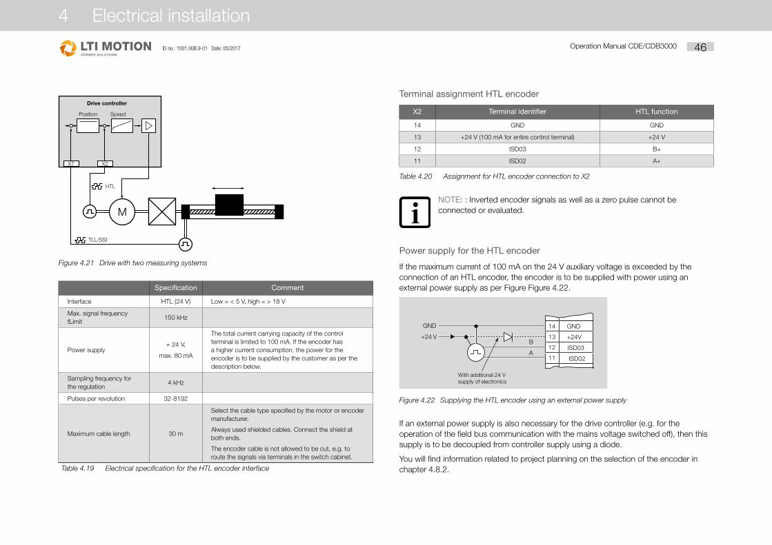
Figure 4.21
M
TLL/SSI
Position Speed
X7 X2
HTL
Drive controller
Drive with two measuring systems
Specification Comment
Interface HTL (24 V) Low = < 5 V, high = > 18 V
Max. signal frequency fLimit
150 kHz
Power supply+ 24 V,
max. 80 mA
The total current carrying capacity of the control terminal is limited to 100 mA. If the encoder has a higher current consumption, the power for the encoder is to be supplied by the customer as per the description below.
Sampling frequency for the regulation
4 kHz
Pulses per revolution 32-8192
Maximum cable length 30 m
Select the cable type specified by the motor or encoder manufacturer.
Always used shielded cables. Connect the shield at both ends.
The encoder cable is not allowed to be cut, e.g. to route the signals via terminals in the switch cabinet.
Table 4.19 Electrical specification for the HTL encoder interface
Terminal assignment HTL encoder
X2 Terminal identifier HTL function
14 GND GND
13 +24 V (100 mA for entire control terminal) +24 V
12 ISD03 B+
11 ISD02 A+
Table 4.20 Assignment for HTL encoder connection to X2
NOTE: : Inverted encoder signals as well as a zero pulse cannot be connected or evaluated.
Power supply for the HTL encoder
If the maximum current of 100 mA on the 24 V auxiliary voltage is exceeded by the connection of an HTL encoder, the encoder is to be supplied with power using an external power supply as per Figure Figure 4.22.
Figure 4.22
14
13
12
11
GND
+24V
ISD03
ISD02A
B+24 V
GND
With additional 24 Vsupply of electronics
Supplying the HTL encoder using an external power supply
If an external power supply is also necessary for the drive controller (e.g. for the operation of the field bus communication with the mains voltage switched off), then this supply is to be decoupled from controller supply using a diode.
You will find information related to project planning on the selection of the encoder in chapter 4.8.2.
Operation Manual CDE/CDB3000 46ID no.: 1001.00B.9-01 Date: 05/2017
4 Electrical installation

4.8.3 Motor connection on the CDB3000
Step Action Comment
1. Specify the cable cross-section depending on the maximum current and ambient temperature.
Cable cross-section as per VDE0100, part 523, see chapter 4.6.
2. Connect the motor phases U, V, W using a shielded cable and earth the motor at X1/.
Connect the shield at both ends to reduce interference emissions.
3. Wire the temperature sensor PTC (if fitted) using separate shielded cables.
Connect the shield at both ends to reduce interference emissions.
CAUTION: It is to be ensured the temperature sensor used is adequately isolated in relation to the motor winding (basic insulation = 2 kV test voltage).
Figure 4.23
X1
U
V
W
M3~
1
V
2
U
W
X21 BG 1- 5 < 15 kWBG 6,7, 7a > 22 kW
X3
Connection of the motor on the CDB3000
NOTE: The CDB3000 positioning controller is protected against short circuits and earth faults on the terminals during operation. If a short circuit or earth fault occurs in the motor cable, the power stage is disabled and an error message is output.
4.8.4 Motor temperature monitoring CDB
CAUTION! The motor temperature sensor must, in relation to the motor winding, on CONNECTION TO X3, be provided with basic insulation!
Connection Sensor type Insulation in the motor winding
X3 (CDE/CDB)
Temperature switch (Klixon), PTC Sensor with basic insulation
Table 4.21 Connection of motor temperature sensor
Shield connection and effective EMC installation
NOTE:
• Connect shield via shield connection STxx. From size 7 (45 kW/ 90 A) the shield connection is to be made directly underneath the device on the backing plate.
• For an effective EMC installation, the motor terminal box must be sealed in relation to HF (metal or metallised plastic). Cable glands with a large area shield connection are to be used for cable entries.
Shield connection plate STxx Shield connection with clip and metal cable ties
NOTE:
• The screws for fastening the shield connection plates ST02 to ST06 are only allowed to be tightened to a tightening torque of max. 1.3 Nm. If this instruction is not followed, the tapped hole on the front of the device may be irreparably damaged.
You will find further information on current carrying capacity, technical data and ambient conditions in annex A.1 to A.3.
Operation Manual CDE/CDB3000 47
4 Electrical installation
ID no.: 1001.00B.9-01 Date: 05/2017

Switching in the motor cable
SWITCHING OFF THE MOTOR:
Motor cable switching must take place with the power switched off, as otherwise problems such as burnt contactor contacts, or over or undervoltage shutdown of the controller may occur.
To ensure unpowered switching, you must make sure that the contacts of the motor contactor are closed before the controller power stage is enabled. Conversely, it is necessary for the contacts to remain closed until the controller power stage is shut down and the motor current is 0.
This is achieved by using appropriate safety delays for the switching of the motor contactor in the control sequence for your machine or using the special software function in the CDE/CDB3000 positioning controller.
MULTI-MOTOR OPERATION:
The positioning controllers CDE3000 can be operated with several motors connected in parallel. Depending on the application, various instructions on project planning must be followed, see appendix A4. Multi-motor operation with the CDB3000 is not allowed.
SWITCHING IN THE MOTOR CABLE WITH THE POWER SWITCHED OFF:
Motor cable switching must always take place with the power switched off, as otherwise a shutdown with a fault may occur.
Figure 4.24
~~= X2/16
X2/17
K1 (ENMO)OSD01(ENMO)
M3 ~
K1
K1M
N
U V W PE
1 3 5
2 4 6
U V W PE
(Start right-side)STR
t
0
0
1
0 1
f [Hz]
STR
Motorcontrol
0 1ENMO/
K1
TENMO TENMO
Connection example for ENMO. The shield connection is not shown.
Operation Manual CDE/CDB3000 48ID no.: 1001.00B.9-01 Date: 05/2017
4 Electrical installation

Principle of operation
Starting the regulation: auxiliary contactor K1 becomes active at the start of regulation. The output frequency (output voltage) of the regulator starts with a delay as set in the parameter 247-TENMO.In this way it is ensured that the motor contactor is closed before the controller's output frequency (output voltage) starts.
Stopping the regulation: on the removal of "Start regulation" the auxiliary contactor K1 is drops out with a delay as set in the parameter 247-TENMO.In this way it is ensured that the motor contactor only opens once the controller power stage is no longer powered.
4.9 Serial interface (SIO) CDE/CDB3000The serial interface (SIO, X4) is used to connect DriveManager 3.x and to connect the KeyPad. The ready made RS232 cable CCD-SUB 90X (maximum length 3 m) is used to connect the positioning controller to the PC / DriveManager 3.x.
Pin assignment X4
Pin no. Function
1 +15 V DC for KeyPad KP300 (formerly KP200-XL)
2 TxD, send data
3 RxD, receive data
4 Do not use
5 GND for +15 V DC for the KeyPad KP300 (formerly KP200-XL)
6 +24 V DC (only for KP200)
7 Do not use
8 Do not use
9 GND for +24 V DC (only for KP200)
Table 4.22 Pin assignment for the serial interface X4, CDE/CDB3000
Figure 4.25
X2
X1
!
X1
X3
X2
X4
OSD 02
OSA0
+10,5V
ERR/WAR
N
READ
Y
POWEER
3 m max.
RS232
RS232
RS232
RS232
CCD-SUB 90X
CCD-SUB 90X
Optotrenner
Grundeinstellungen...
Voreingestellte Lösungen:
Erstinbetriebnahme...
Erweitert >>
Istwerte ...Fehler/Warnung ...
Einstellung in Datei speichern
Hilfe
Abbbrechen
Taktantrieb, Eil-/Schleichgang
X
LTi DRIVEMANAGER
stop start
PE
Connection X4
Operation Manual CDE/CDB3000 49
4 Electrical installation
ID no.: 1001.00B.9-01 Date: 05/2017

CAUTION: The RS232 interface is only used as a service diagnostics interface. Controlling via the interface is not permitted. For reasons related to the circuitry the interface is at the potential of the analogue inputs. Uncontrolled equalisation currents via the cable CCD-SUB 90X may cause irreparable damage to the drive controller and to the PC. We therefore strongly recommend the usage of an optocoupler.
4.10 CAN interface CDE/CDB3000The CANopen interface is integrated into the drive controller. The connection is made via connector X5. The power for the electrically isolated connection is to be provided by the customer.
Connection Miniature D-Sub 9-pin male
Wave terminating resistor
- Bus termination -
A jumper (pin 1-2) activates the internal terminating
resistor (120 W)
Max. input frequency 1 MHz
Ext. power supply+ 24 V +25%, 50 mA
(Floating in relation to the drive controller)
Assignment of connection X5:
X5/pin Function D-Sub
1 Jumper to pin 2 for active bus termination
54
32
1
98
76
X5
CA
N
2 CAN_LOW
3 CAN_GND
4 Do not use
5 Do not use
6 CAN_GND
7 CAN_HIGH
8 Do not use
9 CAN_+24 V external supply voltage
Table 4.23 Pin assignment X5
Bus address
The bus address for a CAN node is set using a coding switch.
X5
X7
X6
S1
X8
WARNINGCapacitor discharge
time > 3 min.Pay attention to theoperation manual!
ACHTUNGKondensatorent-ladezeit > 3 Min.Betriebsanleitungbeachten!
RELRELISDSHISD06ISD05ISD04ISD03ISD02ISD01ISD00+24VDGND
RSHRSH
ENPOOSD02OSD01OSD00ISA1-ISA1+ISA0-ISA0++24VDGND
24
23
22
21
20
19
18
17
16
15
14
13
12
11
10
9
8
7
6
5
4
3
2
1
456789ABCD
EF0
231
X5
X7
WARNINGCapacitor discharge
time > 3 min.Pay attention to the
operation manual!
ACHTUNGKondensatorent-ladezeit > 3 Min.
Betriebsanleitungbeachten!
Ω
WARNINGCapacitor discharge
time > 3 min.Pay attention to the
operation manual!
ACHTUNGKondensatorent-ladezeit > 3 Min.
Betriebsanleitungbeachten!
Ω
456789ABCDEF023 1
45
6789ABCD
EF
0
231CDE 45
6789ABCD
EF
0
231CDB
S1 = CDES3 = CDB
456789ACDEF0
231
B
Example for address:
11 dec = B hex
Figure 4.26 Coding switch position and setting for the CAN bus address
Alternatively, a bus address can be set using parameters. The addresses from the coding switch and the parameter configuration are added together.
PROJECT PLANNING AND FUNCTION DESCRIPTION:
You will find information on this aspect in Communication Manual CANopen. The interface is switched off with the works setting ASTER: OLT_1.
4.11 DC group CDE/CDB3000The positioning controllers that are operated in the DC group (braking operation) supply energy to the DC group; the drive controllers in motor operation consume this energy.
CAUTION: It is imperative operation in a DC group is checked during the project planning. Please consult your project engineer.
Operation Manual CDE/CDB3000 50ID no.: 1001.00B.9-01 Date: 05/2017
4 Electrical installation

4.12 Braking resistor (RB) CDE/CDB3000In regenerative operation, e.g. while braking the drive, the motor feeds energy back to the drive controller. This increases the voltage in the DC link circuit (ZK). If the voltage exceeds a threshold value, the internal braking transistor is activated and the regenerated power is converted into heat by means of a braking resistor.
Figure 4.27
RBRB+
RB-
PE
BG 6, 7, 7a > 22 kW
BG 1-5 < 15 kW
RBL+
RB
PE
X1
X21or
Connection of braking resistor
DANGER! Never make or disconnect electrical connections while they are live! Always disconnect the power before working on the device. Wait until the DC link voltage on the terminals X1/L+ and L- (BG 1-5) or X21/ ZK+, ZK- (BG 6-7) has dropped to the protective extra low voltage before you work on the device (approx. 10 min.).
CAUTION: If the error message E-OTI (overtemperature on the device heat sink) appears, the device connected must be disconnected from the mains supply because the braking resistor may be overloaded due to mains overvoltage. Please connect one of the digital outputs to suit your control concept, e.g. set OSDxx to WOTI (= warning device heat sink temperature).
Connection of an external braking resistor
CAUTION:
• Be sure to follow the installation instructions for the external braking resistor.
• The temperature sensor (bimetallic switch) on the braking resistor must be wired in such a way that the positioning inverter is disconnected from the mains supply if the braking resistor overheats.
• The minimum permissible connection resistance for the positioning inverter must not be infringed, for technical data see appendix 2.
• The braking resistor is integrated in the device model CDE/CDB3X.xxx, Wx.x, BR. It is not allowed to connect an additional braking resistor to terminals X1/L+ or RB+ or RB-; this would damage the inverter module.
• For further information, please consult your project engineer.
Monitoring the internal braking resistor
Model BR
The braking resistor is integrated in the device on model BR - CDB3X.xxx, X, BR positioning controllers. Because, e.g. on mains overvoltage the internal braking resistor may be overloaded, this aspect must be specifically monitored.
You will find the max. permissible peak braking power in appendix A2. For further information, please consult your project engineer.
CAUTION: An external braking resistor must be monitored by the controller. The temperature of the braking resistor is monitored by a temperature sensor (Klixon). In the event of overheating the positioning controller must be disconnected from the mains supply.
Operation Manual CDE/CDB3000 51
4 Electrical installation
ID no.: 1001.00B.9-01 Date: 05/2017

4.13 Safe Torque Off (STO)Applies for all devices CDE3000 as well as for all devices of the special model CDB3000 SH from hardware index 2.4.
NOTE: You will find all information on the "STO" function in the document "CDE/CDB SH/CDF Description of the STO Safety Function" (ID no.:1001.21B.X-XX).
Operation Manual CDE/CDB3000 52ID no.: 1001.00B.9-01 Date: 05/2017
4 Electrical installation

5 Commissioning
CAUTION: Commissioning must only be carried out by electrical engineering experts who have been specially instructed in the necessary accident prevention measures.
5.1 Selection during commissioning
Type of commissioning Commissioning steps Continue on
• Project planning and commissioning have already been undertaken.
• Loading an existing data set.Serial commissioning Page 53
• Project planning and initial drive system commissioning
Initial commissioning Page 54
• Project planning and basic configuration of the drive system have already been undertaken.
Test run Page 60
5.2 Serial commissioningUse this form of commissioning if you want to place in operation several identical drives (serial commissioning). In this situation the same type of positioning controller and the same motor must be used for each drive in the same application.
If you already have a complete data set, please skip the section "Save data set from device to a file" (using DriveManager 3.x).
5.2.1 Serial commissioning using DriveManager 3.xPrerequisite:
• All positioning controllers are completely connected.
• The first drive has already been completely commissioned.
• A PC with the user software DriveManager 3.x is connected.
Step Action Comment
1. Connect your PC to the positioning controller for the first drive and switch on the mains power supply for the positioning controller.
Use a standard serial cable (9-pin D-Sub female/male).
2.Start DriveManager 3.x.
A connection to the positioning controller connected is established automatically.
If the establishment of the connection fails, check the settings on the menu Extras > Options and try again using the button
3. Using the button, save the current data set either in the parameter database for DriveManager 3.x (folder: c:/../userdata) or on a floppy disk (a:/).
The current data set on the device connected is always saved using the button.
Give the file a name of your choice.
4. Close the connection to all devices using the button
Connect your PC to the positioning controller for the next drive and switch on the mains power supply for the positioning controller.
5.Using the button establish a connection between DriveManager 3.x and the newly connected device
6. Using the button load into the device the data set saved in step 4.
7.Using the button open the main window.
Save the setting using the button
Repeat steps 4 ... 7 on each further drive.
NOTE: You will find more information on DriveManager 3.x in the DriveManager Help.
Operation Manual CDE/CDB3000 53
5 Commissioning
ID no.: 1001.20B.9-01 Date: 05/2017

5.3 Initial commissioning
Prerequisites
• The positioning controller is fully connected, see chapter 3
• DriveManager from version V3.4 installed
• Motor database for motors is installed on the PC
• Device is connected via the RS232 interface (X4) on the PC
DANGER: Never make or disconnect electrical connections while they are live! Always disconnect the power before working on the device. Wait until the DC link capacitors are discharged. Only if a residual voltage of less than 60 V (between terminals L+ and L-) is present is it allowed to work on the device!
Input ENPO = low level (CDB terminal 8 (X2) / CDE terminal (X2)) present to prevent unintentional starting of the motor (power stage inhibited, mains voltage for the positioning controller switched on).
Preparations
• Switch on the positioning controller
• A self-test is undertaken Start DriveManager 3.x
Establish connection to the device.
DriveManager 3.x >
Connect
or:
Communication > Connect...
• Open the main window "Setup"DriveManager 3.x or:
Active device > Change settingsFigure 5.1 Main window for making various settings in DriveManager 3.x
Operation Manual CDE/CDB3000 54ID no.: 1001.20B.9-01 Date: 05/2017
5 Commissioning

Continue with:
5.3.1 Preset solutionsPreset solutions are complete parameter data sets for solving a very wide range of typical movement tasks in applications.
Figure 5.2 Initial commissioning
The positioning controller is configured automatically by loading a preset solution into the memory (RAM). The parameters for
• The control location of the drive controller,
• The setpoint source,
• The assignment of the inputs and outputs for the signal processing and
• The control mode
are preset.
The usage of a preset solution significantly simplifies and shortens the commissioning of the positioning controller. The preset solutions can be adapted to the requirements of the user's task by changing individual parameters. Preset solutions modified in this manner are saved in the device as user data sets. In this way you will complete the movement solution you require in less time.
A total of 20 preset solutions cover the typical applications for speed control using the controller CDE/CDB3000.
Operation Manual CDE/CDB3000 55
5 Commissioning
ID no.: 1001.20B.9-01 Date: 05/2017

A total of 20 preset solutions cover the typical applications for speed control using the controller CDE/CDB3000.
Abbreviation Setpoint sourceStarting the regulation via/
bus control profile
TCT_1 +/-10 V analogue - torque I/O terminals
SCT_1 +/-10 V analogue I/O terminals
SCT_2 Fixed speed table I/O terminals
SCC_2 Fixed speed tableCANopen field bus interface
– EasyDrive profile "Basic"
SCB_2 Fixed speed tableField bus option module (PROFIBUS)
– EasyDrive profile "Basic"
SCC_3 CANopen field bus interfaceCANopen field bus interface
– EasyDrive profile "Basic"
SCB_3 Field bus option module (PROFIBUS)Field bus option module (PROFIBUS)
– EasyDrive profile "Basic"
SCP_3 PLC PLC
SCT_4 PLC I/O terminals
SCC_4 PLCCANopen field bus interface
– EasyDrive profile "ProgPos"
SCB_4 PLCField bus option module (PROFIBUS)
– EasyDrive profile "ProgPos"
PCT_2 Driving set tables I/O terminals
PCC_2 Driving set tablesCANopen field bus interface
– EasyDrive profile "TabPos"
PCB_2 Driving set tablesField bus option module (PROFIBUS)
– EasyDrive profile "TabPos"
PCC_1 CANopen field bus interface
CANopen field bus interface
– CiA 402 profile position mode
– CiA 02 profile velocity mode
– CiA 402 interpolated Mode
PCB_1 Field bus option module (PROFIBUS)Field bus option module (PROFIBUS)
– EasyDrive profile "DirectPos"
PCP_1 PLC PLC
Table 5.1 Preset solutions for speed control using CDE/CDB3000
Abbreviation Setpoint sourceStarting the regulation via/
bus control profile
PCT_3 PLC I/O terminals
PCC_3 PLCCANopen field bus interface
– EasyDrive profile "ProgPos"
PCB_3 PLCField bus option module (PROFIBUS)
– EasyDrive profile "ProgPos"
Table 5.1 Preset solutions for speed control using CDE/CDB3000
All preset solutions have a specific basic settings window in DriveManager 3.x.
Procedure
• Select the preset solution to suit your application.
Figure 5.3 Selection of the preset solution
NOTE:For detailed information on the preset solutions and on the terminal assignment, see application manual CDE/CDB3000.
Operation Manual CDE/CDB3000 56ID no.: 1001.20B.9-01 Date: 05/2017
5 Commissioning

5.3.2 Configuration of motor and encoder
Procedure
• Setting the motor data via the motor database
Figure 5.4 Setting motor and encoder
A database with the settings for all motors is available. By using the correct motor data set it is ensured
• That the parameters for the motor's electrical data are configured correctly,
• The motor protection ("Motor protection" tab) is correctly configured and
The control circuits for the drive are preset.
NOTE: The torque controller is optimally configured such that no further changes are necessary.
The speed controller configuration is based on the assumption that the machine moment of inertia scaled to the motor shaft is the same as the motor moment of inertia.
The speed and position controllers have high damping and are therefore also suitable for the regulation of elastic mechanisms.
For special configurations for the optimisation of the speed and position control circuit, please use the application manual for the CDE/CDB3000.
You can select the required motor from the database you have installed using the "Motor selection" button on the "Motor" tab. The motor type is given on the motor rating plate. If the motor data set is supplied on a data carrier (floppy disk, CD-ROM), it can be loaded directly using the "Different directory" button.
Configuration of the rotary encoder
Configure the rotary encoder connected to the motor on the Encoder tab. It is also possible to use two rotary encoders. Here the first rotary encoder is used for motor commutation and speed control (motor encoder), the second rotary encoder for position control (position controller). Both functions can also be realised using only one encoder.
Operation Manual CDE/CDB3000 57
5 Commissioning
ID no.: 1001.20B.9-01 Date: 05/2017

Each encoder combination has a special configuration window.
You will find further information on the configuration of the rotary encoder in the application manual for the CDE/CDB3000.
Checking the rotary encoder
The motor shaft is rotated by hand to check the direction of rotation. The viewing angle is from the front on the end of the shaft (flange). For clockwise rotation, a positive speed must be displayed in the state indication "Setpoint and actual values" in "nist, Actual speed", a negative speed for counter clockwise rotation. If the speed is incorrect, the following points must be checked:
• Is the encoder cable connected correctly on the motor and on the positioning controller?
• Does the encoder cable match the encoder type?
5.3.3 Making basic settingsThere are specific windows for the fine adjustment of each preset solution. Here you can adapt the drive to your application. You will find a detailed description of the individual functions in the application manual CDE/CDB3000.
Procedure
• Making basic settings
Operation Manual CDE/CDB3000 58ID no.: 1001.20B.9-01 Date: 05/2017
5 Commissioning

5.3.4 Saving the settings
Procedure
DriveManager CDE/CDB3000 > Setup or: Active device > Change settings
Saving the settings in the device
All changes that are to be saved in the device must be saved using the CDE/CDB3000 Setup window.
The changes made can also be saved in a file.
Procedure
DriveManager CDE/CDB3000 Setup
or:
Active device > Store device settings on > File
Saving the settings to file
Select the file name (e.g. mydata). All parameters are saved with the selected file name (e.g. mydata) with the corresponding file extension (*.00D). A description can be added to the device data before saving.
Continue with "Test run", see chapter 4.4.
Operation Manual CDE/CDB3000 59
5 Commissioning
ID no.: 1001.20B.9-01 Date: 05/2017

5.4 Test runThe drive is tested without the coupled mechanism. The test run takes place independently of the preset solution selected in the speed-regulated mode.
A test is still possible even if the motor is already coupled to the system:
CAUTION:
Test run with motor installed:
In this case it must be assured that the test will not cause any damage to the system! Pay particular attention to the limitations of the positioning range.
Please note that you yourself are responsible for safe operation. LTi DRiVES GmbH will not accept any liability for any damage caused.
Mortal danger due to uncontrolled rotation!
Before commissioning motors with feather keys in the shaft end, these keys must be reliably secured against throwing out, if this is not already prevented by drive elements such as belt pulleys, couplings or similar.
Preset solution, torque control:
In this preset solution the drive is not allowed to be operated without load torque, because otherwise the motor shaft would be accelerated up to the speed limit set in an uncontrolled manner.
CAUTION:
Irreparable damage to motor:
The motors are intended for operation on the positioning controller. Direct connection to the mains supply can cause irreparable damage to the motor.
The motor surfaces may become extremely hot. No temperature sensitive parts may touch or be fastened to these areas, appropriate measures to prevent physical contact must be taken wherever necessary.
Any temperature sensor installed in the winding is to be connected so that the positioning controller temperature monitoring can prevent overheating of the motor.
The motor brake (if installed) should be checked for correct function before commissioning the motor.
The optionally installed motor holding brake is only designed for a limited number of emergency braking operations. Use as working brake is not allowed.
1. ENABLE SAFE STOP (ONLY CDE3000) High level on terminal X2/22
2. SET POWER STAGE ENABLE ENPO High level on terminal X2/10
t
0
1
0
1
0
1
2 ms
4 ms
ENPO
Start 0
1
Safe standstillSafe stop input
Input ENPO
Start
Device status: "Technology ready"
Pay attention to the behaviour of the inputs over time.
3. CONTROL USING DRIVEMANAGER 3.X: Select "Speed control" and start the drive, e.g. with setpoint 100 min-1.
Procedure
DriveManager 3.x > Control
or:
Active device > Control > Basic operation modes
Operation Manual CDE/CDB3000 60ID no.: 1001.20B.9-01 Date: 05/2017
5 Commissioning

Procedure
DriveManager > Digital scope
or:
Active device > Monitor > Quickly changing digital scope values
Checking the drive behaviour
The drive behaviour can now be evaluated with the aid of step responses that can be recorded using the digital scope function in DriveManager 3.x.
Select the three following parameters to record: - 0: Speed: setpoint - 1: Speed: actual value - 2: Torque: actual value
Trigger condition:
Channel 0; rising edge, pretrigger 10 %; level: 30 min -1
Start the drive using a setpoint of, e.g. 100 min-1.
Operation Manual CDE/CDB3000 61
5 Commissioning
ID no.: 1001.20B.9-01 Date: 05/2017

Compare the step response of your drive with the figure. With resolvers the overshoot on the actual speed value should be approx. 20 %, with incremental encoders approx. 30 % (referred to the setpoint). Make sure that the drive system exhibits a small signal response (the setpoint for the torque must be lower than the maximum value).
If the torque setpoint reaches its maximum value, reduce the speed step.
The behaviour of the speed control circuit over time (rise time, settling time) is independent of the magnitude of the step in the speed.
Result:
If the step response of your drive corresponds approximately to that in the figure, then it is ensured that the motor phases are wired correctly, the rotary encoder is connected correctly and the CDE/CDB3000 is configured for the correct motor.
If the step response differs significantly from the figure, it is to be assumed,
• That the motor data set has been selected incorrectly, or
• The wiring is incorrect.
Check the individual steps in chapter “4.1 Overview of the connections, CDE3000” and chapter “5.3 Initial commissioning” and repeat the test run.
A deviation from the step response is also possible if the ratio of the machine moment of inertia scaled to the motor shaft to the motor moment of inertia is very high. Here it is necessary to optimise the control settings. For special configurations for the optimisation of the speed control circuit and position control circuit, please use the application manual for the CDE/CDB3000.
5.5 Operation using KeyPad KP300The KP 300 can be connected directly to the positioning controller (X4). You will find exact details on the individual functions and their use in the KP300 Operation Manual.
Overview of KeyPad
Designation Summary explanation
KP300
KeyPad with graphic display (128 x 64 pixels) for configuring parameters, actual value indication and serial commissioning of the positioning controller. Display of graphics such as unit status and text for parameters. Language German or English (can be configured). The KeyPad KP300 supports the SmartCard "SC-XL".
Mechanical KP300
H
TB
(1)
stop start
Dimensions (see fig.)
70 x 84 x 37 mm
(W x H x D)
Weight 120 g
Connection (RS232)
Standard (1)Can be connected directly to the drive unit
Mounting the KP300
The KeyPad can be mounted directly on the drive controller or in another position in the switch cabinet and connected via an RS232 cable (e.g. CCD-SUB903) (see drawing).
Please only use self-tapping screws for thermoplastics (e.g. EJOT PT screw, type K30 x 8 WN1412).
Note: The KP300 has degree of protection IP20. Because switch cabinets as a rule have degree of protection IP44 or higher, the KP300
is not allowed to be operated outside the switch cabinet (e.g. cutout in switch cabinet door) without additional protective measures.
3m max.
57,5
52,7
1522,5
55
18
35
12,5
0
0
Operation Manual CDE/CDB3000 62ID no.: 1001.20B.9-01 Date: 05/2017
5 Commissioning

5.6 Operating using DriveManager 3.x
Prerequisite:
• DriveManager from version V3.80 is installed on the PC.
Figure 5.5
DRIVE-MANAGER
3 m max. RS232RS232
CCD-SUB90X
WARNINGCapacitor dischargetime > 3 min.Pay attention to theoperation manual!
ACHTUNGKondensatorent-ladezeit > 3 Min.Betriebsanleitung
beachten!
X4
Connection of positioning controller to PC/DriveManager 3.x
The most important functions
Icon Function Menu
Change setting for the active device Active device > Change settings
Print parameter data set Active device > Print settings
Digital scopeActive device > Monitor > Quickly changing digital scope values
Control drive Active device > Control > Basic operation modes
Establish connection to the device Communication > Connect > Single device
Bus initialisation, change setting Communication > Bus configuration
Icon Function Menu
Disconnect all device connections Communication > Connect
Save data set for the active device to file
Active device > Store device settings on
Transfer data set from file to active device
Active device > Load device settings from
Operation Manual CDE/CDB3000 63
5 Commissioning
ID no.: 1001.20B.9-01 Date: 05/2017

Operation Manual CDE/CDB3000 64ID no.: 1001.20B.9-01 Date: 05/2017
5 Commissioning

6 Diagnostics/troubleshooting
6.1 Light emitting diodesOn the top right of the positioning controller there are three status LEDs in the colours red (H1), yellow (H2) and green (H3).
Device stateRed LED
(H1)Yellow LED
(H2)Green LED
(H3)
Supply voltage is present - - l
H1 H2 H3
Ready (ENPO set) m l l
In operation/autotuning active m l
Warning l l/ l
Error
(Flashing
code)
m l
m LED off, l LED on, LED flashing
6.2 Error messagesIf a malfunction occurs during operation, this situation is indicated by a flashing code on LED H1 (red) on the positioning controller. The code provides an indication of the nature of the error. If a KP300 (formerly KP200-XL) is connected, the KeyPad indicates the type of error as a code.
Flashing code on the
red LED H1
Indication KeyPad
Explanation Cause/solution
1x E-CPU Collective errorThe exact error code can be read via the KeyPad or DriveManager 3.x.
2x E-OFFUndervoltage shutdown
Check mains power supply, appears also briefly on normal mains off.
3x E-OCOvercurrent shutdown
Short circuit, earth fault: check wiring for the power connections, check motor winding, check neutral conductor and earthing (see also chapter 3 Electrical installation.) Device setting not correct: check parameters for the control circuits, check ramp setting.
4x E-OVOvervoltage shutdown
Overvoltage from the mains: check mains voltage, restart device. Overvoltage due to power feedback from the motor (regenerative operation): slow down braking ramps - if not possible, use braking resistor.
5x E-OLMMotor protection shutdown
Motor overloaded (according to I x t monitoring): if possible slow down process cycle, check motor dimensions.
6x E-OLIDevice protection shutdown
Device overloaded: check dimensioning, possibly use a larger device.
7x E-OTMMotor temperature too high
Motor PTC connected correctly? Parameter MOPTC set correctly (type of motor PTC evaluation)? Motor overloaded? Leave motor to cool down, check dimensioning.
8x E-OTIPositioning controller overtemperature
Ambient temperature too high: improve ventilation in the switch cabinet. Load too high on providing drive/braking: check dimensioning, possibly use braking resistor.
1) For further information, also see CDE/CDB/CDF3000 Application Manual
Table 6.1 Error messages
Operation Manual CDE/CDB3000 65
6 Diagnostics/troubleshooting
ID no.: 1001.20B.9-01 Date: 05/2017

If you have any technical queries relating to project planning or commissioning of the drive units, please contact our Helpline.
Helpline
How to reach us:
Mo.-Fr.: 8 a.m. - 5 p.m. Tel. 06441/966-180 E-mail: [email protected] Fax: 06441/966-137
NOTE: If you need more detailed assistance and advice, you will find all the services we offer in the “Support & Service” Order Catalogue available on our web site http://drives.lt-i.com in the section of the same name; you can also download this catalogue from this page.
6.3 User errors during KeyPad operation
Error Cause Rectification
ATT1Parameter is not allowed to be changed or cannot be edited in actual user level.
Select user level 1-MODE or higher.
ATT2Motor is not allowed to be controlled via the CTRL menu.
Remove start signal from the other control location.
ATT3Motor is not allowed to be controlled via the CTRL menu because there is an error state.
Reset error.
ATT4 New parameter value not allowed Change value.
ATT5 New parameter value too high Reduce value.
ATT6 New parameter value too low Increase value.
ATT7 Board cannot be read in the actual state. Reset start signal.
ERROR Invalid password Enter correct password.
Table 6.2 KeyPad user errors: reset using start/enter
6.4 User errors during SmartCard operation
Error Cause Rectification
ERR91 SmartCard write-protected
Use different SmartCard
ERR92 Error during plausibility check
ERR93 SmartCard cannot be read, wrong positioning controller type
ERR94 SmartCard cannot be read, parameters not compatible
ERR96 Connection to the SmartCard interrupted
ERR97 SmartCard data invalid (checksum)
ERR98 Not enough space on SmartCard
ERR99Selected sub-section does not exist on SmartCard, no parameters from SmartCard applied
Table 6.3 SmartCard error: reset using stop/return
Operation Manual CDE/CDB3000 66ID no.: 1001.20B.9-01 Date: 05/2017
6 Diagnostics/troubleshooting

6.5 Error during mains switching
Error Cause Rectification
Mains voltage is present. No reaction from positioning controller (LEDs off).
In the event of excessively frequent switching the device protects itself by means of high-resistance decoupling from the mains.
After a rest phase of a few minutes the device is ready to start once again.
6.6 ResetThe reset function is divided into two areas with different effects. Parameter reset resets to the last value saved in the device. Device reset resets the entire data set to the factory setting (state as delivered).
Parameter reset using KeyPad
If you are in the setting mode for a parameter and press both arrow keys at the same time, the parameter you are editing will be reset to the last setting saved (= saved using parameter 150-SAVE).
Factory setting using KeyPad
Press the two arrow keys at the same time during positioning controller mains-on to set all parameters to the factory setting and re-initialise the controller.
Factory setting using DriveManager 3.x
On the "Active device" menu you can restore the device to the state as delivered using the command "Reset to factory setting".
CAUTION: The preset solution selected will also be reset by the factory setting. Check the terminal assignment and the functionality of the positioning controller in this operation mode or load your user data set.
Operation Manual CDE/CDB3000 67
6 Diagnostics/troubleshooting
ID no.: 1001.20B.9-01 Date: 05/2017

Operation Manual CDE/CDB3000 68ID no.: 1001.20B.9-01 Date: 05/2017
6 Diagnostics/troubleshooting

A Appendix
A.1 Positioning controller current carrying capacity
The maximum permissible positioning controller output current and peak current are dependent on the mains voltage, the motor cable length, the power stage switching frequency and the ambient temperature. If the conditions change, the maximum permissible current carrying capacity of the positioning controller also changes; see following characteristics and tables.
5 35 40 45 50
1
2
IIN
(1)
f [Hz]
(2)
(3)
(4)
Characteristic BG1 to BG5
5 35 40 45 50
1
IIN
Imax
(1)
f [Hz]
(2)
(3)
(4)
Characteristic BG6 to BG7a
Explanations on the characteristics:
(1) Continuous operation
(2) Intermittent operation > 5 Hz rotating field frequency
Peak current see Table A.1 to A.4
(3) Intermittent operation 0 to 5 Hz rotating field frequency
Peak current Imax see Table A.1 to A.4
(4) Pulsed operation
Pulse current = 1.15 times Imax for 20 ms
Project planning rule: T= cycle time < 1 min
Positioning controllers for 230 V systems
Servocontroller
Switching frequency of
the power stage [kHz]
Ambient temperature
[°C]
Rated current
Peak current [Aeff]3)
At 230 V [Aeff]
For intermittent operation 0 to 5 Hz
For intermittent operation
> 5 Hz
For
time4) [s]
CDE/CDB
32.003,Cx.x
4
8
12
16
45
40
40
40
2.4
2.4
2.1
1.8
4.3
4.3
3.75
3.2
4.3
4.3
3.75
3.2
30
CDE/CDB
32.004,Cx.x1)
4
8
12
16
45
40
40
40
4
4
3.5
3
7.2
7.2
5.7
5.0
7.2
7.2
6.3
5.4
30
CDB
32.008,Cx.x1)
CDE/CDB
32.008,Wx.x
4
8
12
16
40
40
40
40
7.1
7.1
6.3
5.5
12.8
12.8
10
8
12.8
12.8
11.35
9.9
30
1) With heat sink HS3... or additional cooling surface3) For 230 V systems4) Shutdown as per I² x t characteristic
Motor cable length 10 m
Installation altitude 1000 m above sea level
Mounted in a row
Table A.1 Positioning controllers for 230 V systems
Operation Manual CDE/CDB3000 69
A Appendix
ID no.: 1001.20B.9-01 Date: 05/2017

Positioning controllers for 400/460 V systems, model "W":
Servocontroller
Switching frequency
of the power stage
Ambient temperature
Rated current Peak current [Aeff]3)
At 400 V
At 460 V
At rotating field frequency
increasing linearly 0 to 5 Hz
For intermittent operation
For
time4) [s]
[kHz] [°C] [Aeff] [Aeff] 0 Hz 5 Hz > 5 Hz
CDE/CDB
34.003,Cx.x
(0.75 kW)
4 45 2.2 2.2 4 4 4 (1.8 IN)
308 40 2.2 2.2 4 4 4 (1.8 IN)
12 40 1.6 1.6 2.9 2.9 2.9 (1.8 IN)
16 40 1.0 1.0 1.8 1.8 1.8 (1.8 IN)
CDE/CDB
34.005,Wx.x
(1.5 kW)
4 45 4.1 4.1 7.4 7.4 7.4 (1.8 IN)
308 40 4.1 3.6 7.4 7.4 7.4 (1.8 IN)
12 40 3.2 2.4 5.7 5.7 5.7 (1.8 IN)
16 40 2.4 1.8 4.3 4.3 4.3 (1.8 IN)
CDE/CDB
34.006,Wx.x
(2.2 kW)
4 45 5.7 5.7 10.3 10.3 10.3 (1.8 IN)
308 40 5.7 5.7 10.31)/7.82) 10.3 10.3 (1.8 IN)
12 40 4.15 3.1 7.51)/6.42) 7.5 7.5 (1.8 IN)
16 40 2.6 1.9 4.7 4.7 4.7 (1.8 IN)
CDE/CDB
34.008,Wx.x
(3 kW)
4 45 7.8 7.8 14 14 14 (1.8 IN)
308 40 7.8 7.8 14 14 14 (1.8 IN)
12 40 6.4 4.8 11 11 11 (1.8 IN)
16 40 5.0 3.7 7.8 9 9 (1.8 IN)
CDE/CDB
34.010,Wx.x
(4 kW)
4 45 10 10 18 18 18 (1.8 IN)
308 40 10 8.8 18 18 18 (1.8 IN)
12 40 8.1 6.0 13 14.5 14.5 (1.8 IN)
16 40 6.2 4.6 7.8 11 11 (1.8 IN)
CDE
34.010, Wx.x,S
4 40 10 10 25 25 25 (2.5 IN)
408 40 10 8.8 18 25 25 (2.5 IN)
12 40 7.0 5.2 13 17.5 17.5 (2.5 IN)
16 40 5.92 4.4 11 14.8 14.8 (2.5 IN)
Table A.2 Positioning controllers for 400/460 V systems, model "W"
Servocontroller
Switching frequency
of the power stage
Ambient temperature
Rated current Peak current [Aeff]3)
At 400 V
At 460 V
At rotating field frequency
increasing linearly 0 to 5 Hz
For intermittent operation
For
time4) [s]
[kHz] [°C] [Aeff] [Aeff] 0 Hz 5 Hz > 5 Hz
CDE/CDB
34.014,Wx.x
(5.5 kW)
4 45 14 14 25 25 25 (1.8 IN)
308 40 14 12.2 25 25 25 (1.8 IN)
12 40 10.3 7.7 18 18 18 (1.8 IN)
16 40 6.6 4.9 12 12 12 (1.8 IN)
CDE/CDB
34.017,Wx.x
(7.5 kW)
4 45 17 17 31 31 31 (1.8 IN)
308 40 17 13.5 31 31 31 (1.8 IN)
12 40 12.5 9.3 23 23 23 (1.8 IN)
16 40 8.0 6.0 14 14 14 (1.8 IN)
CDE/CDB
34.024,Wx.x
(11 kW)
4 45 24.0 24 43 43 43 (1.8 IN)
308 40 24.0 24 43 43 43 (1.8 IN)
12 40 19.5 14 35 35 35 (1.8 IN)
16 40 15 11 27 27 27 (1.8 IN)
CDE/CDB
34.032,Wx.x
(15 kW)
4 45 32 32 58 58 58 (1.8 IN)
308 40 32 28 58 58 58 (1.8 IN)
12 40 26 20 39 47 47 (1.8 IN)
16 40 20 15 32 36 36 (1.8 IN)
1) = CDE
2) = CDB
3) For 400 V systems
4) Shutdown as per I² x t
characteristic
Motor cable length 10 m
Installation altitude 1000 m above
sea level
Mounted in a row
Table A.2 Positioning controllers for 400/460 V systems, model "W"
Operation Manual CDE/CDB3000 70ID no.: 1001.20B.9-01 Date: 05/2017
A Appendix

Positioning controllers for 400/480 V systems, model "W"
Servocontroller
Switching frequency
of the power stage
Ambient temperature
Rated current Peak current [Aeff]3)
At 400 V
At 480 V
At rotating field frequency
increasing linearly 0 to 5 Hz
For intermittent operation
For
time4) [s]
[kHz] [°C] [Aeff] [Aeff] 0 Hz 5 Hz > 5 Hz
CDE
34.044,Wx.x
(22 kW)
4 45 45 41 90 90 90 (2.0 IN)
35)/106)8 40 45 41 90 90 90 (2.0 IN)
12 40 45 41 90 90 90 (2.0 IN)
16 40 42 38 84 84 84 (2.0 IN)
CDE
34.058,Wx.x
(30 kW)
4 45 60 54 120 120 120 (2.0 IN)
35)/106)8 40 60 54 120 120 120 (2.0 IN)
12 40 58 52 116 116 116 (2.0 IN)
16 40 42 38 84 84 84 (2.0 IN)
CDE
34.070,Wx.x
(37 kW)
4 45 72 65 144 144 144 (2.0 IN)
35)/106)8 40 72 65 144 144 144 (2.0 IN)
12 40 58 52 116 116 116 (2.0 IN)
16 40 42 38 84 84 84 (2.0 IN)
CDB
34.044,Wx.x
(22 kW)
4 45 45 41 68 67.5 67 (1.5 IN)
305)8 40 45 41 45 45 67 (1.5 IN)
12 40 36 33 36 36 54 (1.5 IN)
16 40 27 24 27 27 41 (1.5 IN)
CDB
34.070,Wx.x
(37 kW)
4 45 72 65 108 108 108 (1.5 IN)
308 40 72 65 72 72 108 (1.5 IN)
12 40 58 52 58 58 87 (1.5 IN)
16 40 42 38 42 42 63 (1.5 IN)
CDE/CDB
34.088,Wx.x
(47 kW)
4 45 90 81 170 180 180 (2.0 IN)
308 40 90 81 134 180 180 (2.0 IN)
12 40 90 81 107 144 144 (1.6 IN)
16 40 72 65 86 115 115 (1.6 IN)
Table A.3 Positioning controllers for 400/480 V systems, model "W"
Servocontroller
Switching frequency
of the power stage
Ambient temperature
Rated current Peak current [Aeff]3)
At 400 V
At 480 V
At rotating field frequency
increasing linearly 0 to 5 Hz
For intermittent operation
For
time4) [s]
[kHz] [°C] [Aeff] [Aeff] 0 Hz 5 Hz > 5 Hz
CDE/CDB
34.108,Wx.x
(55 kW)
4 45 110 99 170 220 220 (2.0 IN)
308 40 110 99 134 165 165 (1.5 IN)
12 40 90 81 107 144 144 (1.6 IN)
16 40 72 65 86 115 115 (1.6 IN)
CDE/CDB
34.140,Wx.x
(75 kW)
4 45 143 129 270 286 286 (2.0 IN)
308 40 143 129 215 215 215 (1.5 IN)
12 40 115 104 172 172 172 (1.5 IN)
16 40 92 83 138 138 138 (1.5 IN)
CDE/CDB
34.168,Wx.x
(90 kW)
4 45 170 153 190 315 315 (1.9 IN)
108 40 170 153 151 220 220 (1.3 IN)
12 40 136 122 121 164 164 (1.2 IN)
16 40 109 98 97 131 131 (1.2 IN)
1) = CDE
2) = CDB
3) For 400 V systems
4) Shutdown as per I2 x t characteristic
5) At preload of max. 70%
6) At heat sink temperature < 45 °C
Motor cable length 10 m
Installation altitude 1000 m above sea
level
Mounted in a row
Table A.3 Positioning controllers for 400/480 V systems, model "W"
Operation Manual CDE/CDB3000 71
A Appendix
ID no.: 1001.20B.9-01 Date: 05/2017

Positioning controllers for 400/480 V systems, model "L"
Servocontroller
Switching frequency
of the power stage
Ambient temperature
Rated current Peak current [Aeff]3)
At 400 V
At 480 V
At rotating field frequency
increasing linearly 0 to 5 Hz
For intermittent operation
For
time4) [s]
[kHz] [°C] [Aeff] [Aeff] 0 Hz 5 Hz > 5 Hz
CDB.x4.044,L
(22 kW)
4 45 45 41 67.5 67.5 67.5 (1.5 IN)
608 40 45 41 45 45 67.5 (1.5 IN)
12 40 36 41 36 36 54 (1.5 IN)
16 40 27 24 27 27 41 (1.5 IN)
CDE.x4.044,L
(22 kW)
4 45 45 41 90 90 90 (2.0 IN)
308 40 45 41 90 90 90 (2.0 IN)
12 40 45 41 90 90 90 (2.0 IN)
16 40 42 38 84 84 84 (2.0 IN)
CDB.x4.058,L
(30 kW)
4 45 60 54 90 90 90 (1.5 IN)
608 40 60 54 60 60 90 (1.5 IN)
12 40 48 43 48 48 72 (1.5 IN)
16 40 36 33 36 36 54 (1.5 IN)
CDE.x4.058,L
(30 kW)
4 45 60 54 120 120 120 (2.0 IN)
308 40 60 54 120 120 120 (2.0 IN)
12 40 58 52 116 116 116 (2.0 IN)
16 40 42 38 84 84 84 (2.0 IN)
CDB.x4.070,L
(37 kW)
4 45 72 65 108 108 108 (1.5 IN)
608 40 72 65 72 72 108 (1.5 IN)
12 40 58 52 58 58 87 (1.5 IN)
16 40 42 38 42 42 63 (1.5 IN)
CDE.x4.070,L
(37 kW)
4 45 72 65 144 144 144 (2.0 IN)
308 40 72 65 144 144 144 (2.0 IN)
12 40 58 52 116 116 116 (2.0 IN)
16 40 42 38 84 84 84 (2.0 IN)
Table A.4 Positioning controllers for 400/480 V systems, model "L"
Servocontroller
Switching frequency
of the power stage
Ambient temperature
Rated current Peak current [Aeff]3)
At 400 V
At 480 V
At rotating field frequency
increasing linearly 0 to 5 Hz
For intermittent operation
For
time4) [s]
[kHz] [°C] [Aeff] [Aeff] 0 Hz 5 Hz > 5 Hz
CDB/CDE.
x4.088,L
(55 kW)
4 45 110 99 205 220 220 (2.0 IN)
308 45 110 99 165 187 187 (1.7 IN)
12 45 110 99 132 165 165 (1.5 IN)
16 45 90 81 106 135 135 (1.5 IN)
CDB/CDE.
x4.108,L
(75 kW)
4 45 143 129 230 286 286 (2.0 IN)
308 45 143 129 190 215 215 (1.5 IN)
12 45 114 103 152 172 172 (1.5 IN)
16 45 91 82 122 138 138 (1.5 IN)
CDB/CDE.
x4.140,L
(90 kW)
4 45 170 153 230 340 340 (2.0 IN)
108 45 170 153 190 255 255 (1.5 IN)
12 45 136 122 152 204 204 (1.5 IN)
16 45 109 98 122 163 163 (1.5 IN)
CDB/CDE.
x4.168,L
(110 kW)
4 45 210 189 230 340 340 (1.6 IN)
108 45 210 189 190 255 255 (1.2 IN)
12 45 168 151 152 204 204 (1.2 IN)
16 45 134 121 122 163 163 (1.2 IN)
CDB/CDE.
x4.208,L
(110 kW)
4 45 250 225 230 325 325 (1.3 IN)
108 45 250 225 190 255 255 (1.0 IN)
12 45 168 151 152 204 204 (1.2 IN)
16 45 134 121 122 163 163 (1.2 IN)
3) For 400 V systems
4) Shutdown as per I2 x t characteristic
Motor cable length 10 m
Installation altitude 1000 m above sea
level
Mounted in a row
Table A.4 Positioning controllers for 400/480 V systems, model "L"
Operation Manual CDE/CDB3000 72ID no.: 1001.20B.9-01 Date: 05/2017
A Appendix

A.2 Technical dataCDE/CDB32.004,C to CDE/CDB34.006,W
Designation
Technical data
CD
E/C
DB
32.0
03
CD
E/C
DB
32.0
04
CD
E/C
DB
32.0
08
CD
E/C
DB
34.0
03
CD
E/C
DB
34.0
05
CD
E/C
DB
34.0
06
Output, motor side 1) BG1 BG2
Recommended rated power with 4-pole standard motor for CDB
0.375
kW0.75 kW 1.5 kW 0.75 kW 1.5 kW 2.2 kW
Voltage 3 x 0 ... 230 V 3 x 0 ... 400/460 V
Continuous current, effective (IN) 2.4 A 4.3 A 7.1 A 2.2 A 4.1 A 5.7 A
Peak current (See Table A.1) (See Table A.2)
Rotating field frequency 0 ... 400 Hz
Switching frequency of the power stage
4, 8, 12, 16 kHz (factory setting 8 kHz)
Input, mains side
Mains voltage 1 x 230 V -20 % +15 %3 x 400 V (-15 %) ...
3 x 460 V (+10 %)
Device power connection 1.0 kVA 1.6 kVA 3.0 kVA 1.5 kVA 3.0 kVA 4.2 kVA
Asymmetry of mains voltage - ±3 % max.
Frequency 50/60 Hz ±10 % 50/60 Hz ±10 %
Power dissipation CDE at 4 kHz power stage clock frequency 8/16 kHz
49 W
52 W
63 W
70 W
110 W
120 W
90 W
97 W
95 W
127 W
121 W
163 W
Power dissipation CDB at 4 kHz power stage clock frequency 8/16 kHz
35 W
30 W
48 W
55 W
95 W
105 W
55 W
70 W
80 W
112 W
106 W
148 W
Brake chopper power electronics
Peak braking power with int. braking resistor (only model CDE/CDB34 ..., Wx.x, BR)
- -
1.7 kW
with
360 W
-
1.6 kW
with
360 W
1.6 kW
with
360 W
Table A.5 CDE/CDB32.004,C to CDE/CDB34.006,W
Designation
Technical data
CD
E/C
DB
32.0
03
CD
E/C
DB
32.0
04
CD
E/C
DB
32.0
08
CD
E/C
DB
34.0
03
CD
E/C
DB
34.0
05
CD
E/C
DB
34.0
06
Minimum ohmic resistance of an externally installed braking resistor
100 W 56 W 180 W
1) Data apply: for 1-phase devices at 230 V, for 3-phase devices at 400 V
Table A.5 CDE/CDB32.004,C to CDE/CDB34.006,W
CDB34.008,W to CDB34.032,W
Designation
Technical data
CD
E/C
DB
34.0
08
CD
E/C
DB
34.0
10
CD
E34
.010
,W,S
CD
E/C
DB
34.0
14
CD
E/C
DB
34.0
17
CD
E/C
DB
34.0
24
CD
EC
DB
34.0
32
Output, motor side 1) BG3 BG4 BG5
Recommended rated power with 4-pole standard motor for CDB
3.0 kW 4.0 kW - 5.5 kW 7.5 kW 11 kW 15 kW
Voltage 3 x 0 ... 400/460 V
Continuous current, effective (IN) 7.8 A 10 A 10 A 14 A 17 A 24 A 32 A
Peak current (See Table A.2)
Rotating field frequency 0 ... 400 Hz
Switching frequency of the power stage
4, 8, 12, 16 kHz (factory setting 8 kHz)
Input, mains side
Mains voltage 3 x 400 V (-15 %) ... 3 x 460 V (+10 %)
Device power connection5.7
kVA
7.3
kVA
9.4
kVA
10.2
kVA
12.4
kVA
17.5
kVA
23.3
kVA
Asymmetry ±3 % max.
Table A.6 CDB/CDE34.008 to CDB/CDE34.032
Operation Manual CDE/CDB3000 73
A Appendix
ID no.: 1001.20B.9-01 Date: 05/2017

Designation
Technical data
CD
E/C
DB
34.0
08
CD
E/C
DB
34.0
10
CD
E34
.010
,W,S
CD
E/C
DB
34.0
14
CD
E/C
DB
34.0
17
CD
E/C
DB
34.0
24
CD
EC
DB
34.0
32
Frequency 50/60 Hz ±10 %
Power dissipation CDE at 4 kHz power stage clock frequency 8/16 kHz
150 W
177 W
187 W
222 W-
225 W
283 W
270 W
340 W
330 W
415 W
415 W
525 W
Power dissipation CDB at 4 kHz power stage clock frequency 8/16 kHz
135 W
162 W
172 W
207 W-
210 W
268 W
225 W
325 W
315 W
400 W
400 W
510 W
Brake chopper power electronics
Peak braking power with int. braking resistor (only model CDE/CDB34 ..., Wx.x, BR)
6.0 kW with
90 W-
6.0 kW with
90 W
6.0 kW with
90 W
Minimum ohmic resistance of an externally installed braking resistor
81 W 72 W 47 W 22 W
1) Data apply: for 1-phase devices at 230 V, for 3-phase devices at 400 V
Table A.6 CDB/CDE34.008 to CDB/CDE34.032
CDB/CDE34.044,W to CDB/CDE34.168,W
Designation
Technical data
CD
E/C
DB
34.0
44
CD
E/C
DB
34.0
58
CD
E/C
DB
34.0
70
CD
E/C
DB
34.0
88
CD
E/C
DB
34.1
08
CD
E/C
DB
34.1
40
CD
E/C
DB
34.1
68
Output, motor side 1) BG6 BG7 BG7a
Recommended rated power with 2-pole standard motor for CDB
22 kW 30 kW 37 kW 47 kW 55 kW 75 kW 90 kW
Voltage 2) 3 x 0 ... 400/480 V
Continuous current, effective (IN)
45 A 60 A 72 A 90 A 110 A 143 A 170 A
Peak current (See Table A.3)
Rotating field frequency 0 ... 400 Hz
Switching frequency of the power stage
4, 8, 12, 16 kHz (with CDE3000 factory setting 8 kHz)
(with CDB3000 factory setting 4 kHz)
Input, mains side
Mains voltage 3 x 400 V (-15 %) ... 3 x 480 V (+10 %)
Device power connection 31 kVA 42 kVA 50 kVA 62 kVA 76 kVA 99 kVA 118 kVA
Asymmetry ±3 % max.
Frequency 50/60 Hz ±10 %
Power dissipation CDB
CDE
520 W
610 W
700 W
830 W
860 W
1010 W
1050 W
1300 W
1300 W
1600 W
1700 W
2100 W
2000 W
2500 W
Brake chopper power electronics
Minimum ohmic resistance of an externally installed braking resistor
> 18 W > 13 W > 12 W > 10 W > 8.5 W > 6.5 W
1) Data apply: for 1-phase devices at 230 V, for 3-phase devices at 400 V
2) 3 x Umains x 0.95
Table A.7 CDB/CDE34.044,W to CDB/CDE34.168,W
Operation Manual CDE/CDB3000 74ID no.: 1001.20B.9-01 Date: 05/2017
A Appendix

CDB/CDE 34.044,L to CDB/CDE 34.208,L
Designation
Technical data
CD
E/C
DB
34.0
44,L
CD
E/C
DB
34.0
58,L
CD
E/C
DB
34.0
70,L
CD
E/C
DB
34.0
88,L
CD
E/C
DB
34.1
08,L
CD
E/C
DB
34.1
40,L
CD
E/C
DB
34.1
68,L
CD
E/C
DB
34.2
08,L
Output, motor side 1) BG6 BG7 BG7a
Recommended rated power with 2-pole standard motor for CDB
22 kW 30 kW 37 kW 55 kW 75 kW 90 kW110
kW110 kW
Voltage 2) 3 x 0 ... 400/480 V
Continuous current, effective (IN)
45 A 60 A 72 A 110 A 143 A 170 A 210 A 250 A
Peak current (See Table A.4)
Rotating field frequency 0 ... 400 Hz
Switching frequency of the power stage
4, 8, 12, 16 kHz (with CDE3000 and CDB3000 factory setting 4 kHz)
Input, mains side
Mains voltage 3 x 400 V (-15 %) ... 3 x 480 V (+10 %)
Device power connection 31 kVA 42 kVA 50 kVA 76 kVA 99 kVA 118 kVA 128 kVA 128 kVA
Asymmetry ±3 % max.
Frequency 50/60 Hz ±10 %
Power dissipation CDB
CDE
610 W 830 W 1010 W 1950 W 2300 W 2550 W 3000 W 3000 W
Brake chopper power electronics
Minimum ohmic resistance of an externally installed braking resistor
> 10 W > 12 W > 10 W > 8.5 W > 6.5 W > 5 W
1) Data apply: for 1-phase devices at 230 V, for 3-phase devices at 400 V
2) 3 x Umains x 0.95
Table A.8 CDB/CDE 34.044,L to CDB/CDE 34.208,L
A.3 Ambient conditions CDE/CDB3000
Feature Positioning controllerAccessories (KP300 UM-xxxx/ CM-xxxx)
Climatic conditions
In operation as per EN 61800-2, IEC 60721-3-3 class 3K3
+5 ... 40 °C 2) with relative
atmospheric humidity from
5 ... 85 %
without condensation
0 ... 55 °C 2) with relative
atmospheric humidity from
5 ... 85 %
without condensation
In storage as per EN 61800-2,
IEC 60721-3-1 class 1K3 and 1K4
-25 ... +55 °C 3)
with relative atmospheric humidity from 5 ... 95 %
In transit as per EN 61800-2,
IEC 60721-3-2 class 2K3
-25 ... +70 °C 4)
relative atmospheric humidity 95 % at max. +40 °C
Protection
Device IP20 (terminals IP00)
Cooling methodPush-through heat sink
IP54 Convection IP20
Touch protection
BGV 3
Installation altitude
Up to 1000 m above sea level, higher than 1000 m above
sea level with power reduction, max. 2000 m above sea
level
2) The absolute humidity is limited to max. 25 g/m3. That means that the maximum values for temperature and relative
atmospheric humidity stipulated in the table must not occur simultaneously.
3) The absolute humidity is limited to max. 29 g/m3. So the maximum values for temperature and relative atmospheric humidity
stipulated in the table must not occur simultaneously.
4) The absolute humidity is limited to max. 60 g/m3. This means, at 70 °C for example, that the relative atmospheric humidity
may only be max. 40%.
5) The devices are designed only for installation in a stationary switch cabinet.
Operation Manual CDE/CDB3000 75
A Appendix
ID no.: 1001.20B.9-01 Date: 05/2017

Vibration limit in transit, as per EN 61800-2, IEC 60721-3-2 class 2M1
Frequency Amplitude Acceleration
2 < f < 9 Hz 3.5 mm Not applicable
9 < f < 200 Hz Not applicable 10 m/s2
200 < f < 500 Hz Not applicable 15 m/s2
Shock limit in transit as per EN 61800-2, IEC 60721-3-2 class 2M1
Drop height of packed device max. 0.25 m
Vibration limit for the system5), as per EN 61800-2, IEC 60721-3-3 class 3M1
Frequency Amplitude Acceleration
2 < f < 9 Hz 0.3 mm Not applicable
9 < f < 200 Hz Not applicable 1 m/s2
2) The absolute humidity is limited to max. 25 g/m3. That means that the maximum values for temperature and relative
atmospheric humidity stipulated in the table must not occur simultaneously.
3) The absolute humidity is limited to max. 29 g/m3. So the maximum values for temperature and relative atmospheric humidity
stipulated in the table must not occur simultaneously.
4) The absolute humidity is limited to max. 60 g/m3. This means, at 70 °C for example, that the relative atmospheric humidity
may only be max. 40%.
5) The devices are designed only for installation in a stationary switch cabinet.
A.4 Usage of a mains choke
The usage of mains chokes is necessary:
• On the usage of the positioning controller in applications with interference corresponding to environment class 3, as per EN 61000-2-4 and higher (hostile industrial environment).
• If the DC links on several positioning controllers are coupled.
The characteristics of environment class 3 include:
• Mains voltage fluctuations > + 10 % UN
• Brief interruptions between 10 ms and 60 s
• Voltage asymmetry > 3 %
Environment class 3 is typically present if:
• A major portion of the load is supplied by power converters (DC choppers or soft-starting devices)
• There are welding machines
• There are induction furnaces or electric arc furnaces
• Large motors are started frequently
• Current loads fluctuate quickly.
Operation Manual CDE/CDB3000 76ID no.: 1001.20B.9-01 Date: 05/2017
A Appendix

Mains load (example)
Without mains choke With mains choke Change
4 kW positioning
controller, mains
impedance 0.6 mH
4 kW positioning
controller, mains
impedance 6 mH
Without mains
choke compare
to with mains
choke
Distortion (THD)1) 99 % 33 % -67 %
Mains current amplitude 18.9 A 9.7 A -48 %
Mains current, effective 8.5 A 6.23 A -27 %
Commutation dips referred to the mains voltage
28 V 8 V -70%
Service life of the DC link capacitors Rated service life2 to 3 times rated
service life+100 to 200 %
1) THD = Total Harmonic Distortion (harmonic U5 ...U41)
Table A.9 Change in the mains load due to usage of a mains choke with 4 % short-circuit voltage based on the example of a 4 kW positioning controller CDB34.010
Mains voltage asymmetry (example)
Without mains choke With mains choke
4 kW positioning controller,
mains impedance 0.6 mH
4 kW positioning controller,
mains impedance 6 mH
Asymmetry of mains voltage 0 % +3 % -3 % 0 % +3 % -3 %
Mains current amplitude 18.9 A 25.4 A 25.1 A 9.7 A 10.7 A 11 A
Mains current, effective 8.5 A 10.5 A 10.2 A 6.2 A 6.7 A 6.8 A
Table A.10 Effect of the mains choke with asymmetrical mains voltage based on the example of a 4 kW positioning controller CDE/CDB34,010
RECOMMENDATION: The example shows that the benefits of a mains choke with 4 % short-circuit voltage are multi-faceted.We therefore recommend you to use a mains choke in principle.
A.5 Mains filtersYou will find details on the topic of "electromagnetic compatibility" in chapter 4.3.
Permissible motor cable length with internal RFI filter
Drive
controller
4 kHz power stage clock
frequency
With integrated mains filter
8 kHz power stage clock
frequency
With integrated mains filter
16 kHz power stage clock
frequency
With integrated mains filter
Industrial Residential Industrial Residential Industrial Residential
CDE/B32.003 1) 1) 20 10 25 10
CDE/B32.004 1) 1) 20 10 25 10
CDE/B32.006 25 10 20 10 25 10
CDE/B32.008 25 10 20 10 25 10
CDE/B34.003 10 10 25 10 1) 1)
CDE/B34.005 10 10 25 10 25 1)
CDE/B34.006 10 10 25 10 25 1)
CDE/B34.008 25 10 25 10 20 1)
CDE/B34.010 25 10 25 10 20 1)
CDE/B34.014 10 1) 25 102) 20 1)
CDE/B34.017 10 1) 25 102) 20 1)
CDE/B34.044 25 10 25 10 - -
CDE/B34.058 25 10 25 10 - -
CDE/B34.070 25 10 25 10 - -
1), 2) See Table A.12
Table A.11 Permissible motor cable length with integrated mains filter as a function of the standard 61800-3
Operation Manual CDE/CDB3000 77
A Appendix
ID no.: 1001.20B.9-01 Date: 05/2017

Explanations on Table A.11
Residential:
Limit according to EN 61800-3 (first environment), restricted availability.
Maximum permissible motor cable length with which the interference emissions (>9 kHz) are below the permissible limits. Only 10/ 15 m were checked during the measurements.
Industrial:
Limit according to EN 61800-3 (second environment), restricted availability.
Maximum permissible motor cable length with which the interference emissions (>9 kHz) are below the permissible limits. Only 25 m was checked during the measurements.
1)
The interference emissions at 10 m and/or 25 m were above the limits stipulated by the standard. However, this does not mean that the mains filter is ineffective, but only that it is not acting optimally over the entire frequency band. An external mains filter must therefore be used to comply with the standard.
2)A mains choke (uK = 2 % or 4 %) must also be connected in series to comply with the standard.
12 kHz
Power stage clock frequency
At a 12 kHz power stage clock frequency, external mains filters must be used because there are no measurements available with an internal mains filter.
Measuring method:The permissible length of the motor cable was determined as per the standard (stipulated measuring method).
Table A.12 Explanations on Table A.11
A.6 UL certificationThe description of all measures to maintain UL approval is to be found in the document "UL-Certification" (ID no.: 0927.21B.X.xx).
Operation Manual CDE/CDB3000 78ID no.: 1001.20B.9-01 Date: 05/2017
A Appendix

B Glossary
AAppendix ............................................................................................. 69Assignment for HTL encoder connection to X2 .................................... 46Assignment for the rotary encoder interface X7 .................................... 45
BBrake driver X9 .................................................................................... 33Braking resistor (RB) CDE/CDB ........................................................... 50
CCAN interface CDE/CDB ..................................................................... 49Capacitor charging ................................................................................ 7CDE/CDB ambient conditions ............................................................. 76Characteristics ..................................................................................... 69Checking the drive behaviour ............................................................... 61Circuit category ..................................................................................... 8Cold plate ............................................................................................ 13Commissioning .................................................................................... 53Configuration of motor and encoder .................................................... 57Configuration of the rotary encoder ...................................................... 57Connection diagram, CDB3000 ..................................................... 22, 23Connection diagram, CDE3000 ..................................................... 19, 20Connection example for ENMO ........................................................... 48Connection of an external braking resistor ........................................... 51Connection of braking resistor ............................................................. 50Connection of LTI motors .................................................................... 38Connection of motors from other manufacturers .................................. 38Connection of positioning controller to PC/DriveManager 3.x ............... 63Connection of the motor on the CDB ................................................... 46Connection of the PTC ........................................................................ 39
Connection X4 ..................................................................................... 49Control connections CDB .................................................................... 40Control connections CDE .................................................................... 31Control terminals, drive ........................................................................ 43Cooling with cold plate ........................................................................ 13Cutout for push-through heat sink ....................................................... 14
DDC group CDE/CDB ............................................................................ 50Dimensional drawings liquid cooling..................................................... 17Dimensional drawings push-through heat sink ..................................... 15Dimensional drawings wall mounting ................................................... 12Disclaimer .............................................................................................. 4Disposal ................................................................................................ 4Drive with two measuring systems ....................................................... 45
EEffective EMC installation ..................................................................... 25Electrical installation ......................................................................... 3, 19Electrical isolation concept .................................................................. 27Electrical specification for the HTL rotary encoder interface ................. 45EN61000-3-2 ...................................................................................... 31EN 61800 ............................................................................................ 38ENMO ................................................................................................. 48Environment class ............................................................................... 30Error during mains switching ................................................................ 67Error messages ................................................................................... 65External mains filter .............................................................................. 25
FFactory setting ..................................................................................... 33
Operation Manual CDE/CDB3000 79
B Glossary
ID no.: 1001.20B.9-01 Date: 05/2017

IID no. ................................................................................................... 2Initial commissioning ...................................................................... 54, 55Intended use ......................................................................................... 8Interference on the analogue input ....................................................... 28Internal mains filter ............................................................................... 25
KKey to connection diagram ............................................................ 19, 22Key to connection diagram, CDB3000 ................................................ 23Key to connection diagram, CDE3000 ................................................. 20
LLayout of the CDB3000 ....................................................................... 24Layout of the CDE3000 ....................................................................... 21Light emitting diodes ........................................................................... 65Liquid cooling ...................................................................................... 16
MMains connection CDE/CDB ............................................................... 29Mains filter ........................................................................................... 77Mains voltage asymmetry .................................................................... 77Main window for making various settings in DriveManager 3.x ............. 54Making basic settings .......................................................................... 58Measures for your safety ........................................................................ 7Mechanical installation ......................................................................... 11Monitoring the internal braking resistor ................................................ 51Motor cable length ............................................................................... 77Motor connection on the CDB ............................................................. 46Motor protection tab ............................................................................ 40Mounting clearances ............................................................... 11, 14, 16Multi-motor operation .......................................................................... 47
NNotes for operation .............................................................................. 11
OOperating using DriveManager 3.x ....................................................... 63Operation using KeyPad KP300 .......................................................... 62Overview of the connections, CDB ...................................................... 22Overview of the connections, CDE ....................................................... 19
PPictograms ............................................................................................ 5Pin assignment for the serial interface .................................................. 49Pin assignment X4 ............................................................................... 49Pin assignment X5 ............................................................................... 49Pin assignment X6 ............................................................................... 36Positioning controller current carrying capacity .................................... 69Positioning controllers for 230 V systems ............................................. 69Positioning controllers for 400/460 V systems W ................................. 70Positioning controllers for 400/480 V systems L................................... 72Positioning controllers for 400/480 V systems W ................................. 71Power supply ...................................................................................... 27Power supply for the HTL encoder ...................................................... 46Preset solutions ............................................................................. 55, 56Project planning and function description ............................................ 50Project planning and installation rules .................................................. 26Protective earth conductor connection CDE/CDB ................................ 26Push-through heat sink ........................................................................ 13
RReady made encoder cable ................................................................. 35Removal of the electrical isolation ........................................................ 28Reset ................................................................................................. 67Responsibility ........................................................................................ 9
Operation Manual CDE/CDB3000 80ID no.: 1001.20B.9-01 Date: 05/2017
B Glossary

Rotary encoder connection .................................................................. 36Rotary encoder connection CDB ......................................................... 44Rotary encoder connection CDE ......................................................... 33Rotary encoder interface X7 ................................................................ 37
SSafe Torque Off (STO) .......................................................................... 51Safety 3, 7Saving the settings .............................................................................. 59Scope of supply .................................................................................... 4Selection during commissioning .......................................................... 53Selection of the preset solution ............................................................ 56Serial commissioning ........................................................................... 53Serial commissioning using DriveManager 3.x ..................................... 53Serial interface ..................................................................................... 49Setting motor and encoder .................................................................. 57Specification for the rotary encoder interface X7 .................................. 44Specification of the control connections CDB ...................................... 41Specification of the control connections CDE ...................................... 32Star topology for the PE conductor ...................................................... 26STO ................................................................................................. 51Support & Service ................................................................................. 5Switching in the motor cable ............................................................... 47Switching in the motor cable with the power switched off .................... 48Switching off the motor: ....................................................................... 47
TTechnical data ............................................................................... 35, 73Test run ............................................................................................... 60Trigger condition .................................................................................. 61
UUL approval ......................................................................................... 78Usage of a mains choke ...................................................................... 76
Usage of the analogue inputs as digital inputs ..................................... 27User errors during KeyPad operation ................................................... 66User errors during SmartCard operation .............................................. 66
WWall mounting ...................................................................................... 11
XX5 ........................................................................................... 38, 47X6 ................................................................................................. 38X7 ................................................................................................. 38
Operation Manual CDE/CDB3000 81
B Glossary
ID no.: 1001.20B.9-01 Date: 05/2017

Operation Manual CDE/CDB3000 82ID no.: 1001.20B.9-01 Date: 05/2017
B Glossary

Operation Manual CDE/CDB3000 83ID no.: 1001.20B.9-01 Date: 05/2017

Copyright ©
All content of the documentation, in particular the text, photographs and graphics it contains are protected by copyright. The copyright lies, unless otherwise expressly stated, with LTI Motion GmbH.
LTI Motion GmbH
Gewerbestraße 5-9 35633 Lahnau Germany Phone +49 (0) 64 41 - 9 66 - 0 Fax +49 (0) 64 41 - 9 66 - 137
www.lti-motion.com [email protected]