Bode Plot (contd.) Series and Parallel Resonancemshashmi/CTD_2016/Lecture_Slides/Lect_16... · •...
15
ECE215 Lecture – 16 Date: 20.10.2016 • Bode Plot (contd.) • Series and Parallel Resonance
Transcript of Bode Plot (contd.) Series and Parallel Resonancemshashmi/CTD_2016/Lecture_Slides/Lect_16... · •...
ECE215
Lecture – 16 Date: 20.10.2016
• Bode Plot (contd.)• Series and Parallel Resonance
ECE215
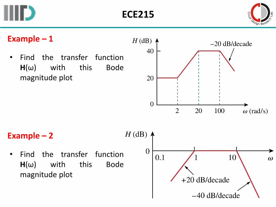
Example – 1
• Find the transfer functionH(ω) with this Bodemagnitude plot
Example – 2
• Find the transfer functionH(ω) with this Bodemagnitude plot
ECE215
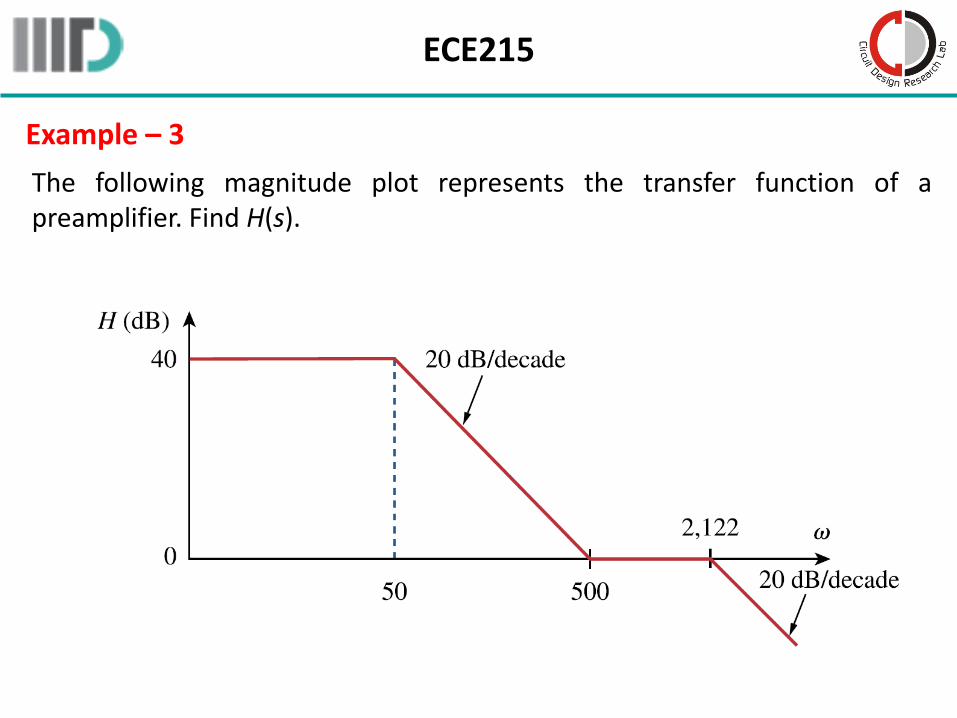
Example – 3
The following magnitude plot represents the transfer function of apreamplifier. Find H(s).
ECE215
Series Resonance
• Resonance occurs in any system that has a complex conjugate pair ofpoles; it is the cause of oscillations of stored energy from one form toanother.
• It allows frequency discrimination in communications networks.
Resonance is a condition in an RLC circuit in which the capacitive and inductive reactances are equal in magnitude, thereby resulting in a
purely resistive impedance.
Resonant circuits (series or parallel) are useful for constructing highly frequency selective filters. They are used in many applications such
as selecting the desired stations in radio and TV receivers.
ECE215
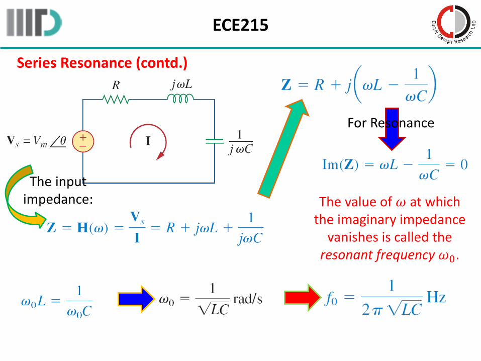
Series Resonance (contd.)
The input impedance:
For Resonance
The value of 𝜔 at which the imaginary impedance
vanishes is called the resonant frequency 𝜔0.
ECE215
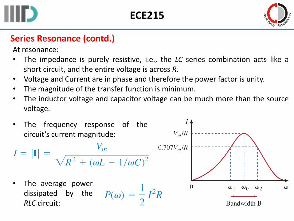
Series Resonance (contd.) At resonance:• The impedance is purely resistive, i.e., the LC series combination acts like a
short circuit, and the entire voltage is across R.• Voltage and Current are in phase and therefore the power factor is unity.• The magnitude of the transfer function is minimum.• The inductor voltage and capacitor voltage can be much more than the source
voltage.
• The frequency response of thecircuit’s current magnitude:
• The average powerdissipated by theRLC circuit:
ECE215
Series Resonance (contd.)
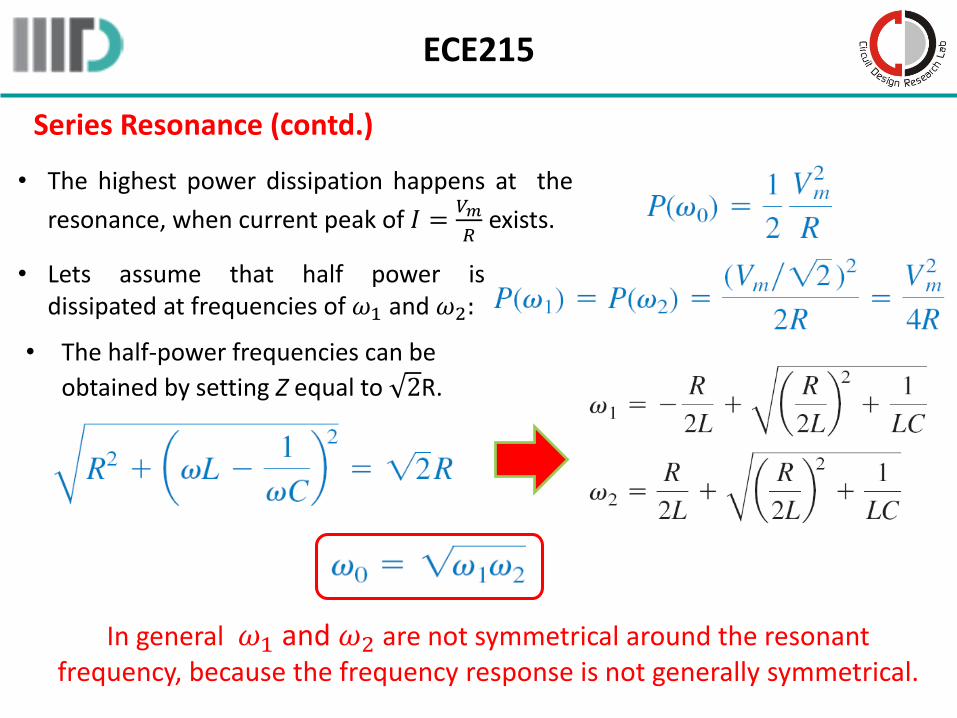
• The highest power dissipation happens at the
resonance, when current peak of 𝐼 =𝑉𝑚
𝑅exists.
• Lets assume that half power isdissipated at frequencies of 𝜔1 and 𝜔2:
• The half-power frequencies can be
obtained by setting Z equal to 2R.
In general 𝜔1 and 𝜔2 are not symmetrical around the resonant frequency, because the frequency response is not generally symmetrical.
ECE215
Series Resonance (contd.)
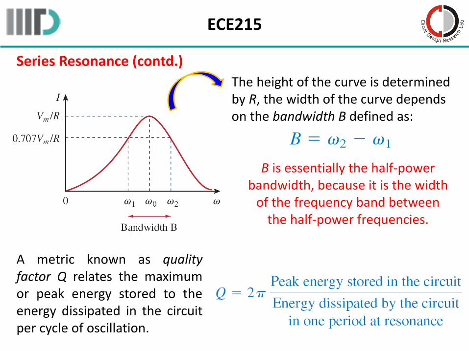
The height of the curve is determined by R, the width of the curve depends on the bandwidth B defined as:
B is essentially the half-power bandwidth, because it is the width
of the frequency band between the half-power frequencies.
A metric known as qualityfactor Q relates the maximumor peak energy stored to theenergy dissipated in the circuitper cycle of oscillation.
ECE215
Series Resonance (contd.)
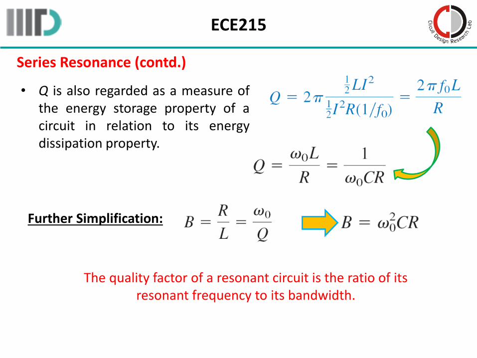
• Q is also regarded as a measure ofthe energy storage property of acircuit in relation to its energydissipation property.
Further Simplification:
The quality factor of a resonant circuit is the ratio of its resonant frequency to its bandwidth.
ECE215
Series Resonance (contd.)
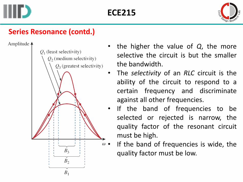
• the higher the value of Q, the moreselective the circuit is but the smallerthe bandwidth.
• The selectivity of an RLC circuit is theability of the circuit to respond to acertain frequency and discriminateagainst all other frequencies.
• If the band of frequencies to beselected or rejected is narrow, thequality factor of the resonant circuitmust be high.
• If the band of frequencies is wide, thequality factor must be low.
ECE215
Series Resonance (contd.)
• A resonant circuit is designed to operate at or near its resonantfrequency.
• It is said to be a high-Q circuit when its quality factor is equal to orgreater than 10 𝑄 ≥ 10 .
• For high-Q circuits the half-power frequencies are, for all practicalpurposes, symmetrical around the resonant frequency and can beapproximated as:
a resonant circuit is characterized by five related parameters: the two half-power frequencies 𝜔1 and 𝜔2, the resonant frequency 𝜔0, the
bandwidth B, and the quality factor Q.
ECE215
Example – 4
A series RLC network has R = 2 kΩ, L = 40 mH, and C = 1 μF. Calculate theimpedance at resonance and at one-fourth, one-half, twice, and four timesthe resonant frequency.
A coil with resistance 3Ω and inductance 100 mH is connected in serieswith a capacitor of 50 pF, a resistor of 6Ω and a signal generator that gives110 V rms at all frequencies. Calculate 𝜔0, Q, and B at resonance of theresultant series RLC circuit.
Example – 5
Design a series RLC circuit with B = 20 rad/s and 𝜔0 = 1,000 rad/s. Find the circuit’s Q. Let R = 10Ω.
Example – 6
ECE215
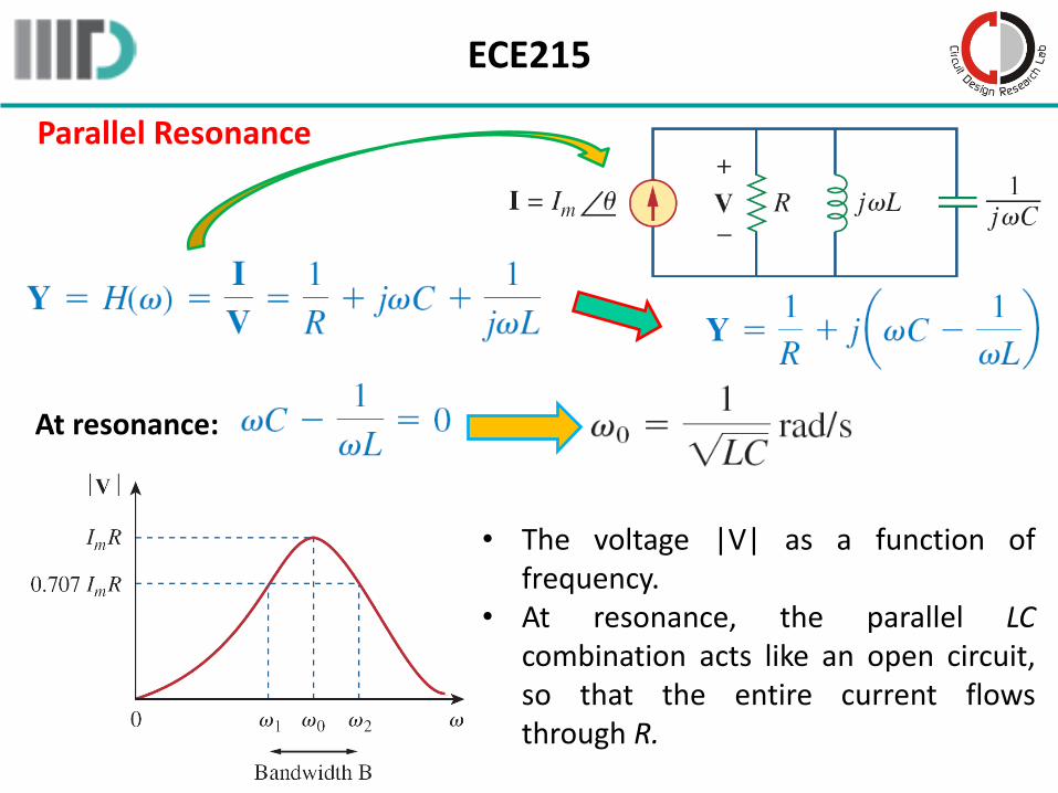
Parallel Resonance
At resonance:
• The voltage |V| as a function offrequency.
• At resonance, the parallel LCcombination acts like an open circuit,so that the entire current flowsthrough R.
ECE215
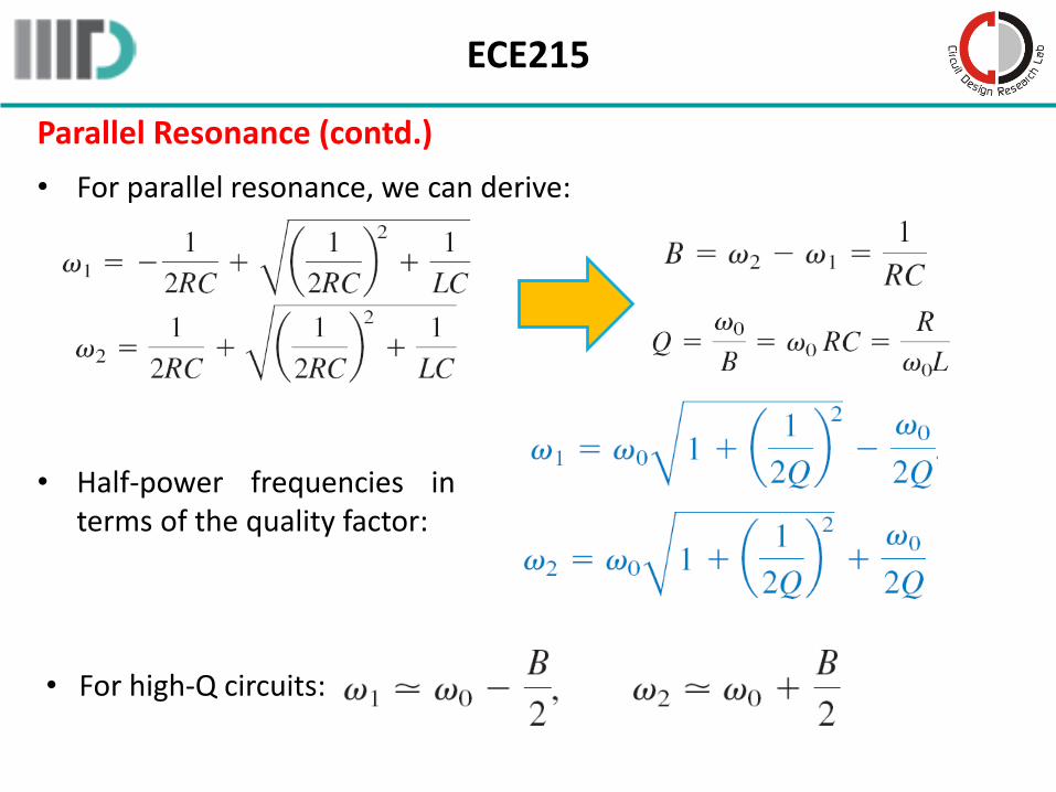
Parallel Resonance (contd.)
• For parallel resonance, we can derive:
• Half-power frequencies interms of the quality factor:
• For high-Q circuits:
ECE215
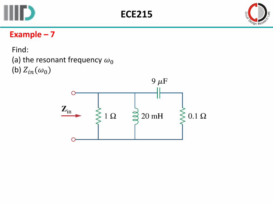
Example – 7
Find:(a) the resonant frequency 𝜔0
(b) 𝑍𝑖𝑛(𝜔0)