BDS Design Issues with Short-Bunch LC Configurations
30
AWLC2020 October 22, 2020 BDS Design Issues with Short-Bunch LC Configurations Glen White, SLAC
Transcript of BDS Design Issues with Short-Bunch LC Configurations
AWLC2020
October 22, 2020
BDS Design Issues with
Short-Bunch LC Configurations
Glen White,
SLAC
Overview
• Recent interest in collider options with short-bunch configurations -> long-term
vision of ILC…
• Conventional and advanced (e.g. PWFA) acceleration technology
• arXiv:2010.00680 (3 TeV γγ collider with σz=5μm)
• Snowmass LOI’s• SNOWMASS21-EF0_EF0-CF7_CF0-TF6_TF0-AF6_AF0-CompF2_CompF0-037(2).pdf
Particle Colliders with Ultra-Short Bunches LoI to Energy Frontier
• SNOWMASS21-AF1-008.pdf
Beam Physics of Extreme Bunch Compression
• SNOWMASS21-EF1-AF1-015.pdf
Short-Bunch Paradigm Laserless γγ Collider
• SNOWMASS21-CF1-001.pdf
Probing QED Cascades and Pair Plasmas in Laboratory Experiments
• SNOWMASS21-TF1-001.pdf
Understanding the Fully Non-Perturbative Strong-Field Regime of QED
• Implications for BDS design to maintain beam quality and provide clean
environment to detectors
• Large energy spread, CSR, space-charge, backgrounds
Recently proposed short-bunch collider parameters raise challenges for BDS design 2
3 TeV PWFA LC γγ beam parameter study
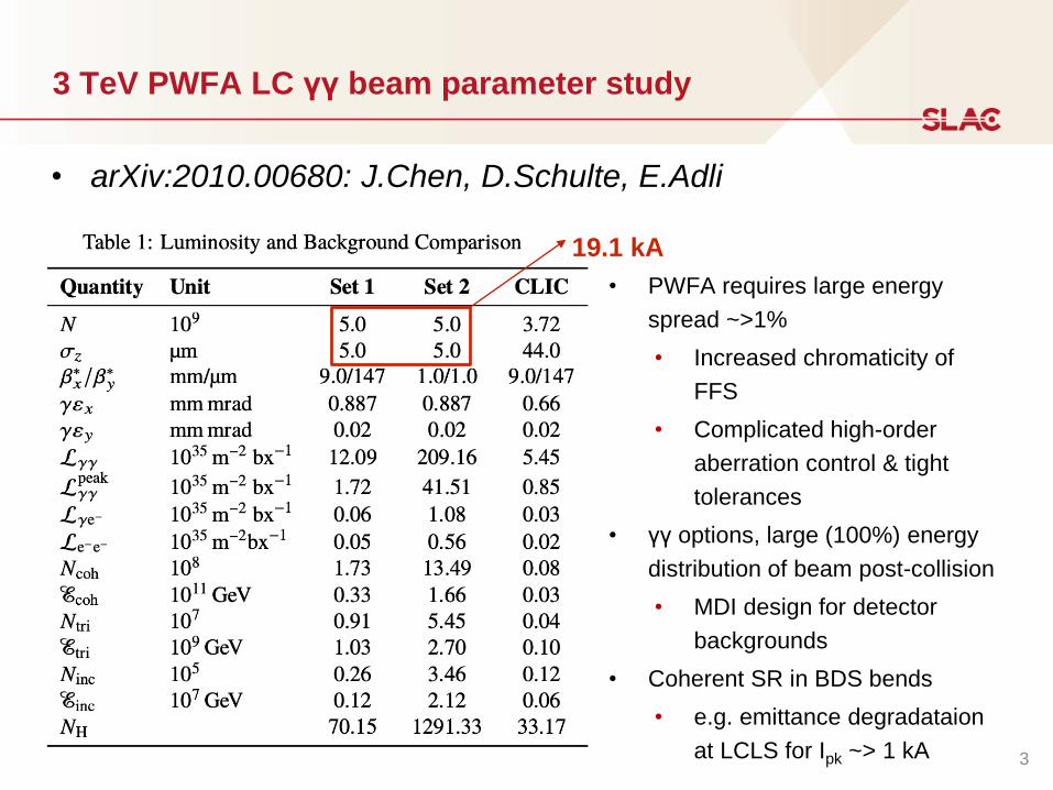
• arXiv:2010.00680: J.Chen, D.Schulte, E.Adli
3
• PWFA requires large energy
spread ~>1%
• Increased chromaticity of
FFS
• Complicated high-order
aberration control & tight
tolerances
• γγ options, large (100%) energy
distribution of beam post-collision
• MDI design for detector
backgrounds
• Coherent SR in BDS bends
• e.g. emittance degradataion
at LCLS for Ipk ~> 1 kA
19.1 kA
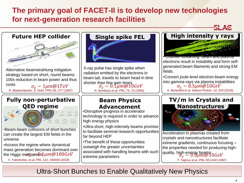
The primary goal of FACET-II is to develop new technologies
for next-generation research facilities
4
• Counter-streaming beam and plasma
electrons result in instability and form self-
generated beam filaments and strong EM
fields.
•Convert joule-level electron-beam energy
into gamma-rays via plasma instabilities
High intensity γ rays
𝜎𝑧 ∼ 0.5𝜇𝑚@10𝐺𝑒𝑉A. Benedetti et al. Nature Photon. 12, 319 (2018)
Acceleration in plasmas created from
crystals and nanostructures facilitate
extreme gradients, continuous focusing –
the properties needed for producing high-
quality, high-energy beams
TV/m in Crystals and Nanostructures
T. Tajima, et.al. PRL 59,1440 (1987)
𝜎𝑧 ∼ 0.3𝜇𝑚@10𝐺𝑒𝑉
X-ray pulse has single spike when
radiation emitted by the electrons in
beam tail, travels to beam head in time
shorter than few gain times
Single spike FEL
R. Bonifacio et al. PRL 73, 70 (1994)
𝜎𝑧 ∼ 0.1𝜇𝑚@10𝐺𝑒𝑉
Future HEP collider
Alternative beamstrahlung mitigation
strategy based on short, round beams:
100x reduction in beam power and thus
costs 𝜎𝑧 ∼ 1𝜇𝑚@1𝑇𝑒𝑉R. Blankenbecler, S. Drell, PRD 36, 277 (1987)
Beam Physics Advancement
•Disruptive progress in accelerator
technology is required in order to advance
high energy physics
•Ultra-short, high-intensity beams promise
to facilitate seminal research opportunities
far beyond HEP
•The benefit of these opportunities
outweigh the greater uncertainties
associated with handling beams with such
extreme parameters
•Beam-beam collisions of short bunches
can create the largest EM fields in the
universe
•Access the regime where dynamical
mass generation becomes dominant over
the Higgs mechanism
V. Yakimenko, et.al. PRL 122, 190404 (2019)
Fully non-perturbative QED regime
𝜎𝑧 ∼ 0.1𝜇𝑚@100𝐺𝑒𝑉
Ultra-Short Bunches to Enable Qualitatively New Physics
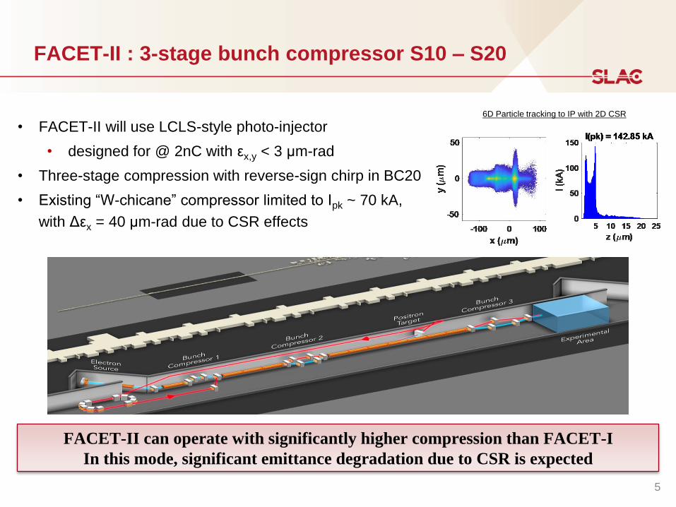
FACET-II : 3-stage bunch compressor S10 – S20
• FACET-II will use LCLS-style photo-injector
• designed for @ 2nC with εx,y < 3 μm-rad
• Three-stage compression with reverse-sign chirp in BC20
• Existing “W-chicane” compressor limited to Ipk ~ 70 kA,
with Δεx = 40 μm-rad due to CSR effects
FACET-II can operate with significantly higher compression than FACET-I
In this mode, significant emittance degradation due to CSR is expected
6D Particle tracking to IP with 2D CSR
5
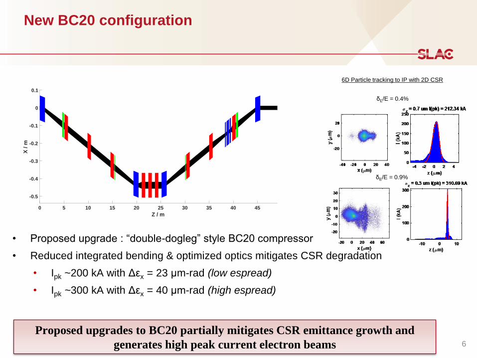
New BC20 configuration
• Proposed upgrade : “double-dogleg” style BC20 compressor
• Reduced integrated bending & optimized optics mitigates CSR degradation
• Ipk ~200 kA with Δεx = 23 μm-rad (low espread)
• Ipk ~300 kA with Δεx = 40 μm-rad (high espread)
6D Particle tracking to IP with 2D CSR
δE/E = 0.9%
δE/E = 0.4%
Proposed upgrades to BC20 partially mitigates CSR emittance growth and
generates high peak current electron beams 6
0 5 10 15 20 25 30 35 40 45
Z / m
-0.5
-0.4
-0.3
-0.2
-0.1
0
0.1
X /
m
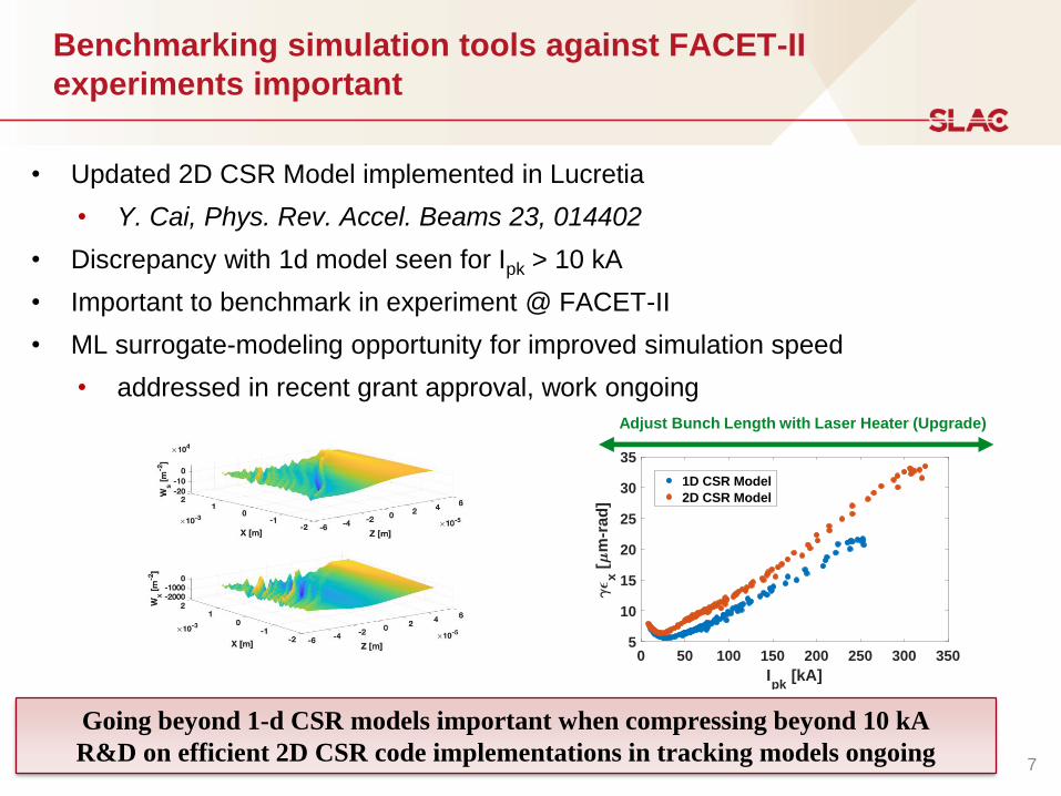
Benchmarking simulation tools against FACET-II
experiments important
• Updated 2D CSR Model implemented in Lucretia
• Y. Cai, Phys. Rev. Accel. Beams 23, 014402
• Discrepancy with 1d model seen for Ipk > 10 kA
• Important to benchmark in experiment @ FACET-II
• ML surrogate-modeling opportunity for improved simulation speed
• addressed in recent grant approval, work ongoing
0 50 100 150 200 250 300 350
Ipk
[kA]
5
10
15
20
25
30
35
x [
m-r
ad
]
1D CSR Model
2D CSR Model
Adjust Bunch Length with Laser Heater (Upgrade)
Going beyond 1-d CSR models important when compressing beyond 10 kA
R&D on efficient 2D CSR code implementations in tracking models ongoing7
Definition of design targets for emittance compensated CSR
bunch compressor: FACET-III in ESA @ 30 GeV
1 μm-rad level emittance at <μm rms bunch length at a meaningful charge
(Ipk>100kA)
• 70 – 125 GeV for HEP collider
• 10 – 30 GeV for extreme power FEL applications (𝑃𝑥𝑟𝑎𝑦 ≈ 𝜌𝑃𝑏𝑒𝑎𝑚)
• Assumptions:
• Join FACET-II & LCLS Cu LINAC for 30 GeV in ESA to study limits of CSR
emittance-compensated bunch compression
• for electron injector: εn = 0.5 μm-rad @ Q = 2 nC
• (TOPGUN) – Injector R&D not discussed here
Conduct feasibility study for CSR emittance-compensated bunch compressor
8
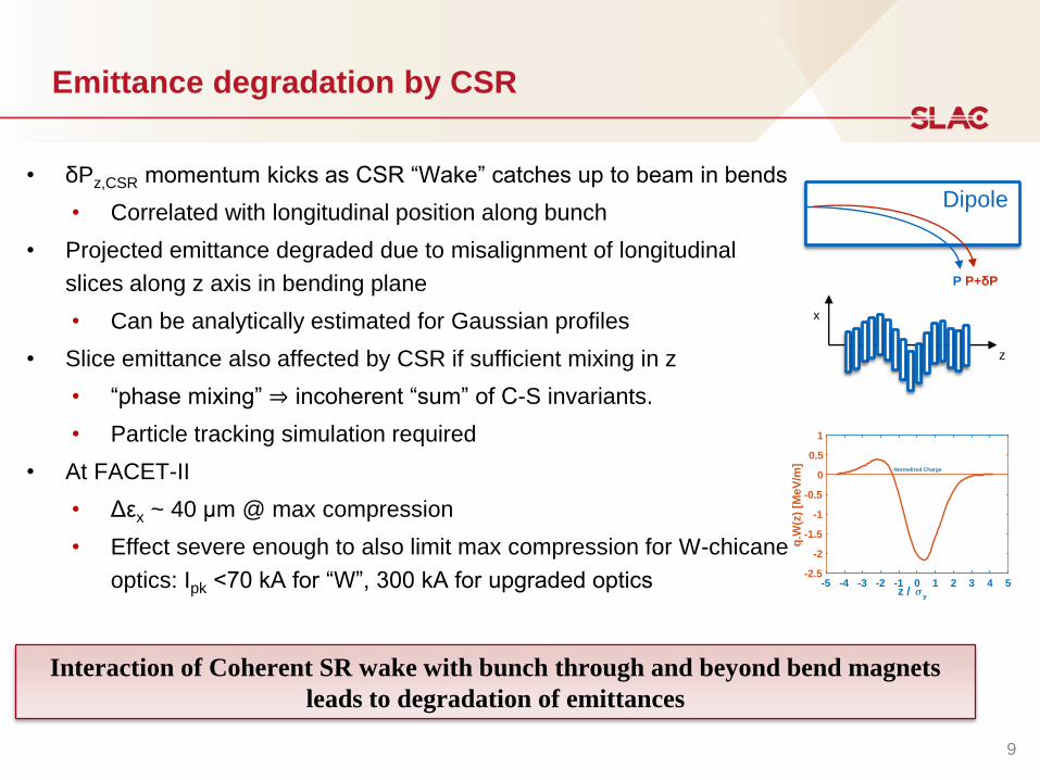
Emittance degradation by CSR
• δPz,CSR momentum kicks as CSR “Wake” catches up to beam in bends
• Correlated with longitudinal position along bunch
• Projected emittance degraded due to misalignment of longitudinal
slices along z axis in bending plane
• Can be analytically estimated for Gaussian profiles
• Slice emittance also affected by CSR if sufficient mixing in z
• “phase mixing” ⇒ incoherent “sum” of C-S invariants.
• Particle tracking simulation required
• At FACET-II
• Δεx ~ 40 μm @ max compression
• Effect severe enough to also limit max compression for W-chicane
optics: Ipk <70 kA for “W”, 300 kA for upgraded optics
Dipole
P P+δP
z
x
9
Interaction of Coherent SR wake with bunch through and beyond bend magnets
leads to degradation of emittances
-5 -4 -3 -2 -1 0 1 2 3 4 5z /
z
-2.5
-2
-1.5
-1
-0.5
0
0.5
1
q.W
(z)
[Me
V/m
]
Normalized Charge
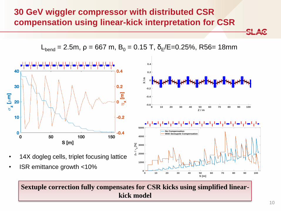
30 GeV wiggler compressor with distributed CSR
compensation using linear-kick interpretation for CSR
• 14X dogleg cells, triplet focusing lattice
• ISR emittance growth <10%
Lbend = 2.5m, ρ = 667 m, B0 = 0.15 T, δE/E=0.25%, R56= 18mm
0 10 20 30 40 50 60 70 80 90 100
Z / m
-0.6
-0.4
-0.2
0
0.2
0.4
X /
m
Sextuple correction fully compensates for CSR kicks using simplified linear-
kick model
0 10 20 30 40 50 60 70 80 90 100
S [m]
0
1000
2000
3000
4000
5000
/
0 [
%]
No Compensation
With Sextupole Compensation
10
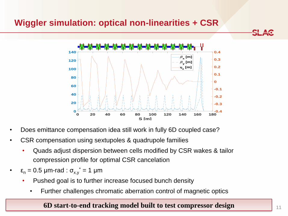
Wiggler simulation: optical non-linearities + CSR
• Does emittance compensation idea still work in fully 6D coupled case?
• CSR compensation using sextupoles & quadrupole families
• Quads adjust dispersion between cells modified by CSR wakes & tailor
compression profile for optimal CSR cancelation
• εn = 0.5 μm-rad : σx,y* = 1 μm
• Pushed goal is to further increase focused bunch density
• Further challenges chromatic aberration control of magnetic optics
0 20 40 60 80 100 120 140 160 180
S [m]
0
20
40
60
80
100
120
140
-0.4
-0.3
-0.2
-0.1
0
0.1
0.2
0.3
0.4
x [m]
y [m]
x [m]
6D start-to-end tracking model built to test compressor design 11
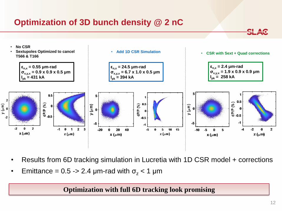
Optimization of 3D bunch density @ 2 nC
εn,x = 0.55 μm-rad
σx,y,x = 0.9 x 0.9 x 0.5 μm
Ipk = 431 kA
εn,x = 24.5 μm-rad
σx,y,x = 6.7 x 1.0 x 0.5 μm
Ipk = 394 kA
εn,x = 2.4 μm-rad
σx,y,x = 1.9 x 0.9 x 0.9 μm
Ipk = 258 kA
• No CSR
• Sextupoles Optimized to cancel
T566 & T166• Add 1D CSR Simulation • CSR with Sext + Quad corrections
• Results from 6D tracking simulation in Lucretia with 1D CSR model + corrections
• Emittance = 0.5 -> 2.4 μm-rad with σz < 1 μm
Optimization with full 6D tracking look promising
12
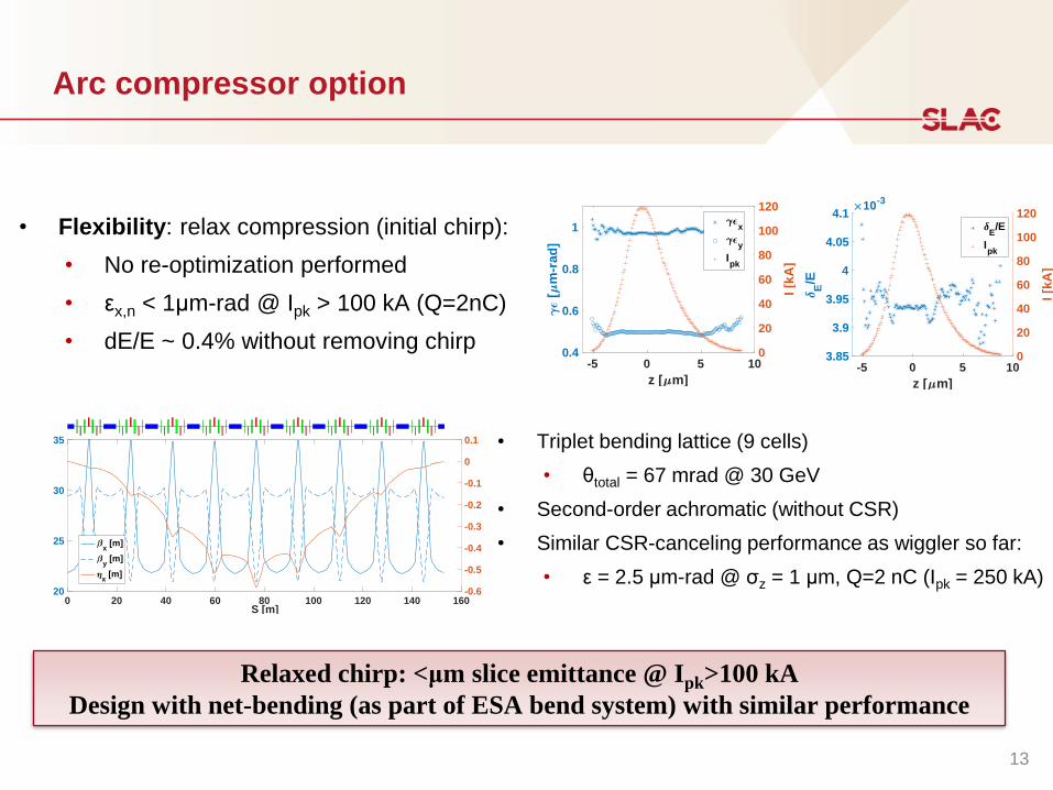
Arc compressor option
• Triplet bending lattice (9 cells)
• θtotal = 67 mrad @ 30 GeV
• Second-order achromatic (without CSR)
• Similar CSR-canceling performance as wiggler so far:
• ε = 2.5 μm-rad @ σz = 1 μm, Q=2 nC (Ipk = 250 kA)0 20 40 60 80 100 120 140 160
S [m]
20
25
30
35
-0.6
-0.5
-0.4
-0.3
-0.2
-0.1
0
0.1
x [m]
y [m]
x [m]
-5 0 5 10
z [ m]
0.4
0.6
0.8
1
[m
-ra
d]
0
20
40
60
80
100
120
I [k
A]
x
y
Ipk
-5 0 5 10
z [ m]
3.85
3.9
3.95
4
4.05
4.1
E/E
10-3
0
20
40
60
80
100
120
I [k
A]
E/E
Ipk
• Flexibility: relax compression (initial chirp):
• No re-optimization performed
• εx,n < 1μm-rad @ Ipk > 100 kA (Q=2nC)
• dE/E ~ 0.4% without removing chirp
Relaxed chirp: <μm slice emittance @ Ipk>100 kA
Design with net-bending (as part of ESA bend system) with similar performance
13
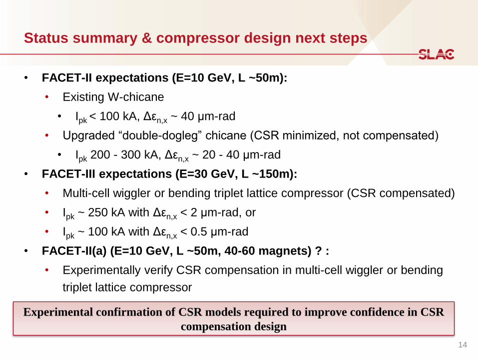
Status summary & compressor design next steps
• FACET-II expectations (E=10 GeV, L ~50m):
• Existing W-chicane
• Ipk < 100 kA, Δεn,x ~ 40 μm-rad
• Upgraded “double-dogleg” chicane (CSR minimized, not compensated)
• Ipk 200 - 300 kA, Δεn,x ~ 20 - 40 μm-rad
• FACET-III expectations (E=30 GeV, L ~150m):
• Multi-cell wiggler or bending triplet lattice compressor (CSR compensated)
• Ipk ~ 250 kA with Δεn,x < 2 μm-rad, or
• Ipk ~ 100 kA with Δεn,x < 0.5 μm-rad
• FACET-II(a) (E=10 GeV, L ~50m, 40-60 magnets) ? :
• Experimentally verify CSR compensation in multi-cell wiggler or bending
triplet lattice compressor
Experimental confirmation of CSR models required to improve confidence in CSR
compensation design
14
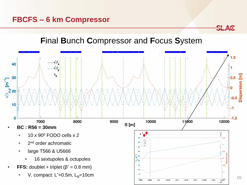
FBCFS – 6 km Compressor
Final Bunch Compressor and Focus System
• BC : R56 = 30mm
• 10 x 900 FODO cells x 2
• 2nd order achromatic
• large T566 & U5666
• 16 sextupoles & octupoles
• FFS: doublet + triplet (β* = 0.8 mm)
• V. compact: L*=0.5m, LB=10cm15
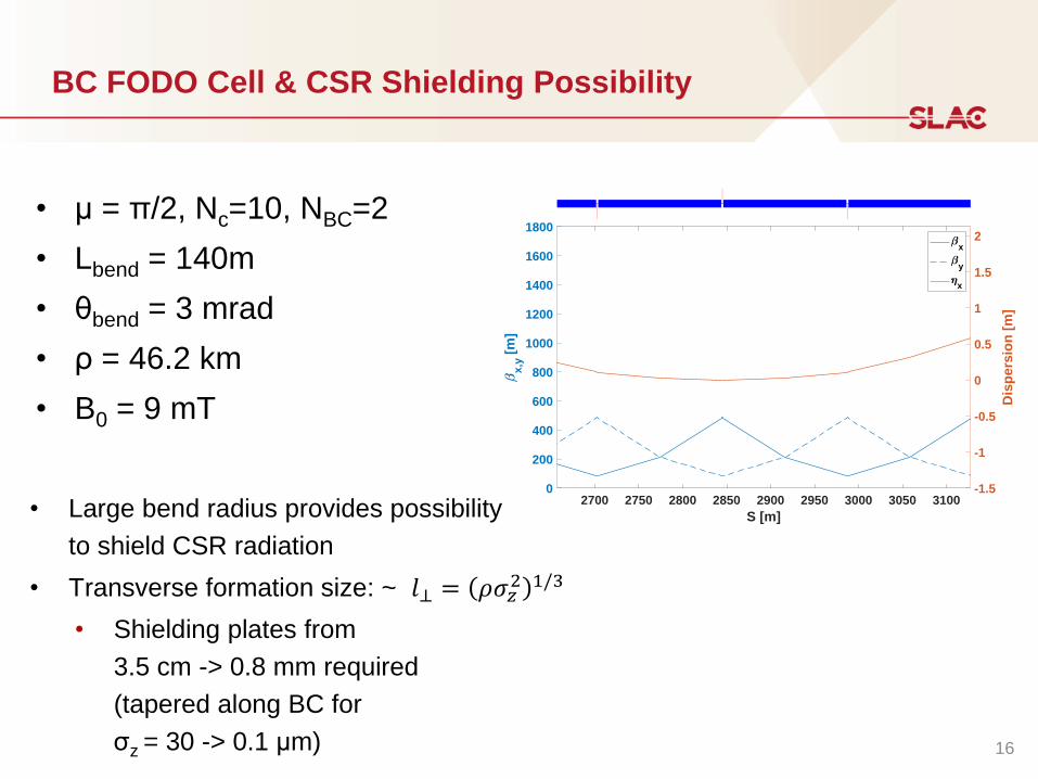
BC FODO Cell & CSR Shielding Possibility
• μ = π/2, Nc=10, NBC=2
• Lbend = 140m
• θbend = 3 mrad
• ρ = 46.2 km
• B0 = 9 mT
2700 2750 2800 2850 2900 2950 3000 3050 3100
S [m]
0
200
400
600
800
1000
1200
1400
1600
1800
x,y
[m
]
-1.5
-1
-0.5
0
0.5
1
1.5
2
Dis
pe
rsio
n [
m]
x
y
x
𝑙⊥ = 𝜌𝜎𝑧2 1/3
• Large bend radius provides possibility
to shield CSR radiation
• Transverse formation size: ~
• Shielding plates from
3.5 cm -> 0.8 mm required
(tapered along BC for
σz = 30 -> 0.1 μm) 16
Next steps: Collective effects modeling R&D
• 1D CSR model implemented within Lucretia tracking code
(similar to Elegant simulation)
• Extending to deal with changing geometries & shielding (a la BMAD)
• 2D/3D CSR solutions being studied, benchmark at FACET-II & apply to these designs
• e.g. currently deployed 2D model omits transient effects: developing theory to
address this
• expected to be small perturbations in results
• Improve tracking speed to allow more sophisticated optimization algorithms
• GPU algorithm implemented
• R&D ongoing in conjunction with ML group on surrogate modeling
• Compression work (longitudinal space charge) effects expected to be important
• adding to tracking simulations.
CSR modeling based on existing 1D models
R&D ongoing to improve 2/3D, optimize execution speed & benchmark
17
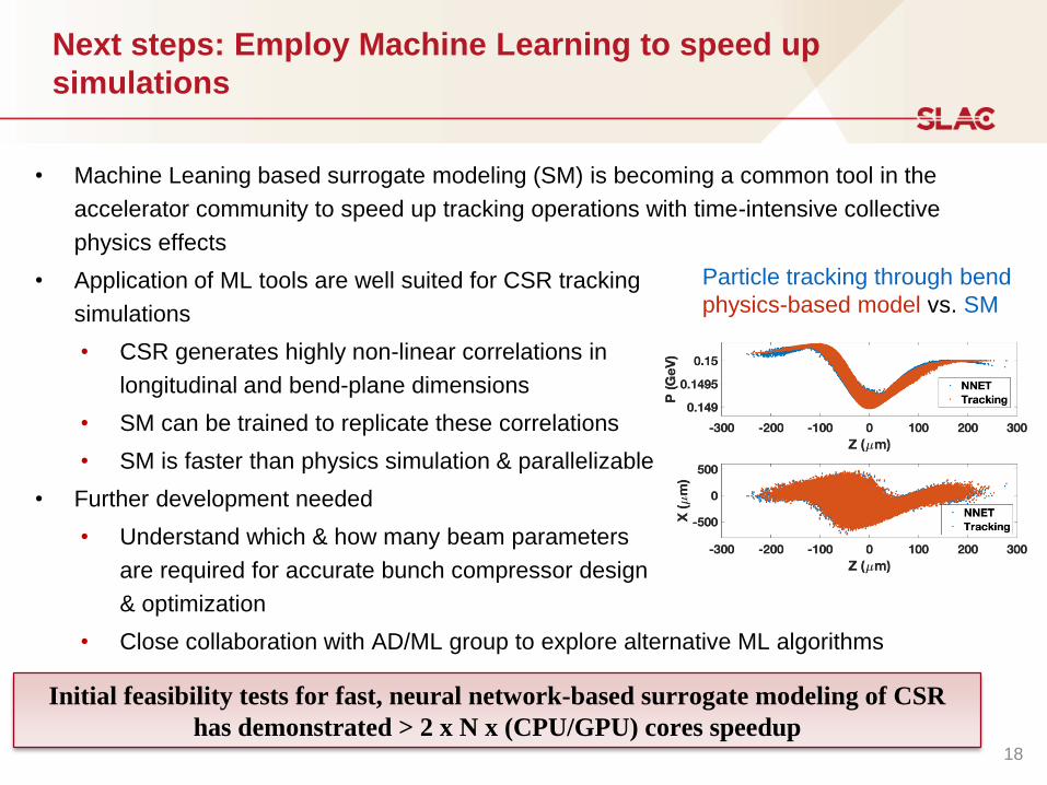
Next steps: Employ Machine Learning to speed up
simulations
• Machine Leaning based surrogate modeling (SM) is becoming a common tool in the
accelerator community to speed up tracking operations with time-intensive collective
physics effects
• Application of ML tools are well suited for CSR tracking
simulations
• CSR generates highly non-linear correlations in
longitudinal and bend-plane dimensions
• SM can be trained to replicate these correlations
• SM is faster than physics simulation & parallelizable
• Further development needed
• Understand which & how many beam parameters
are required for accurate bunch compressor design
& optimization
• Close collaboration with AD/ML group to explore alternative ML algorithms
Initial feasibility tests for fast, neural network-based surrogate modeling of CSR
has demonstrated > 2 x N x (CPU/GPU) cores speedup18
Particle tracking through bend
physics-based model vs. SM
Backup Slides
19
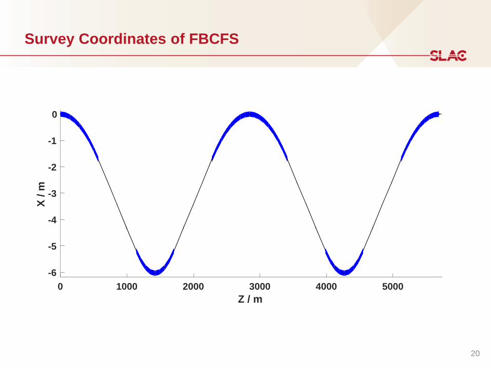
Survey Coordinates of FBCFS
0 1000 2000 3000 4000 5000
Z / m
-6
-5
-4
-3
-2
-1
0
X /
m
20
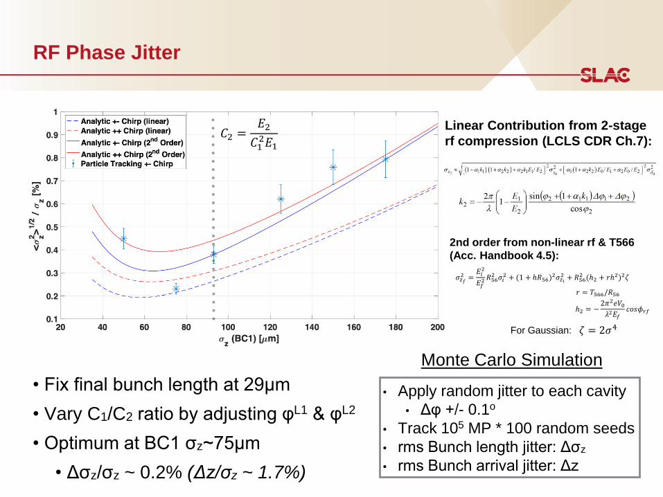
RF Phase Jitter
• Fix final bunch length at 29μm
• Vary C1/C2 ratio by adjusting φL1 & φL2
• Optimum at BC1 σz~75μm
• Δσz/σz ~ 0.2% (Δz/σz ~ 1.7%)
• Apply random jitter to each cavity
• Δφ +/- 0.1o
• Track 105 MP * 100 random seeds
• rms Bunch length jitter: Δσz
• rms Bunch arrival jitter: Δz
Monte Carlo Simulation
𝐶2 =𝐸2
𝐶12𝐸1
𝜎𝑧𝑓2 =
𝐸𝑖2
𝐸𝑓2 𝑅56
2 𝜎𝑖2 + (1 + ℎ𝑅56)
2𝜎𝑧𝑖2 + 𝑅56
2 (ℎ2 + 𝑟ℎ2)2𝜁
𝑟 = 𝑇566/𝑅56
ℎ2 = −2𝜋2𝑒𝑉0𝜆2𝐸𝑓
𝑐𝑜𝑠𝜙𝑟𝑓
Linear Contribution from 2-stage
rf compression (LCLS CDR Ch.7):
2nd order from non-linear rf & T566
(Acc. Handbook 4.5):
𝜁 = 2𝜎4For Gaussian:
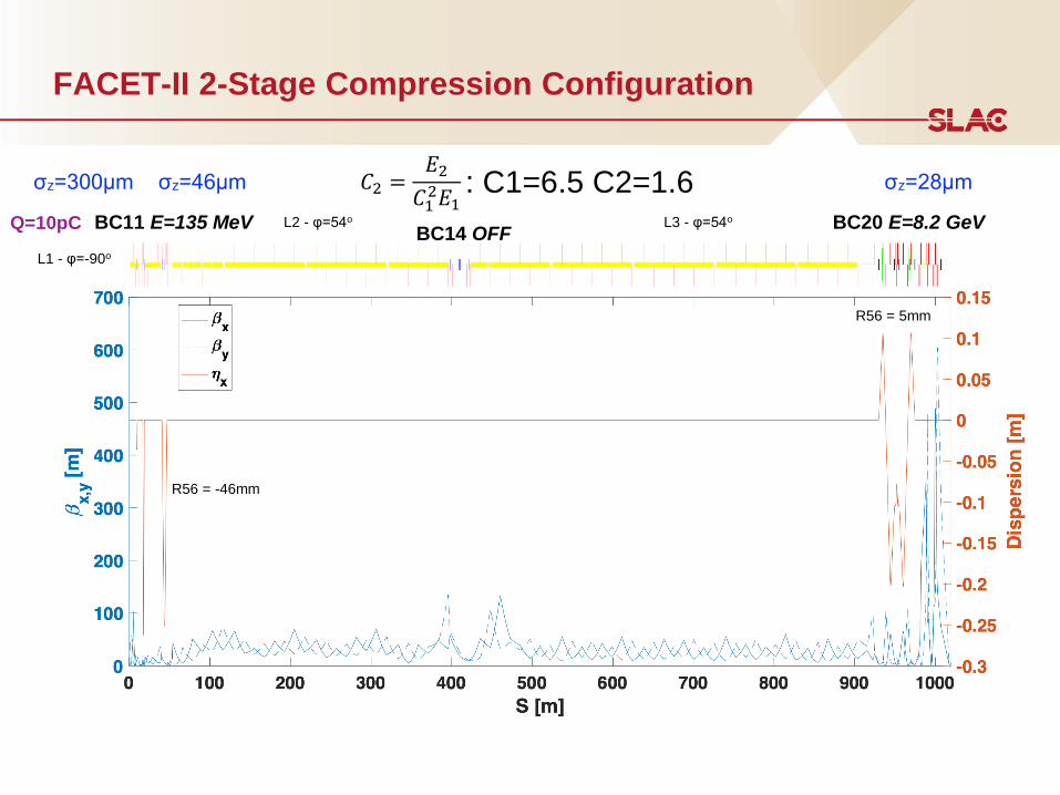
FACET-II 2-Stage Compression Configuration
BC14 OFFBC11 E=135 MeV BC20 E=8.2 GeV
𝐶2 =𝐸2
𝐶12𝐸1
: C1=6.5 C2=1.6σz=300μm σz=46μm σz=28μm
L2 - φ=54o L3 - φ=54o
L1 - φ=-90o
Q=10pC
R56 = 5mm
R56 = -46mm
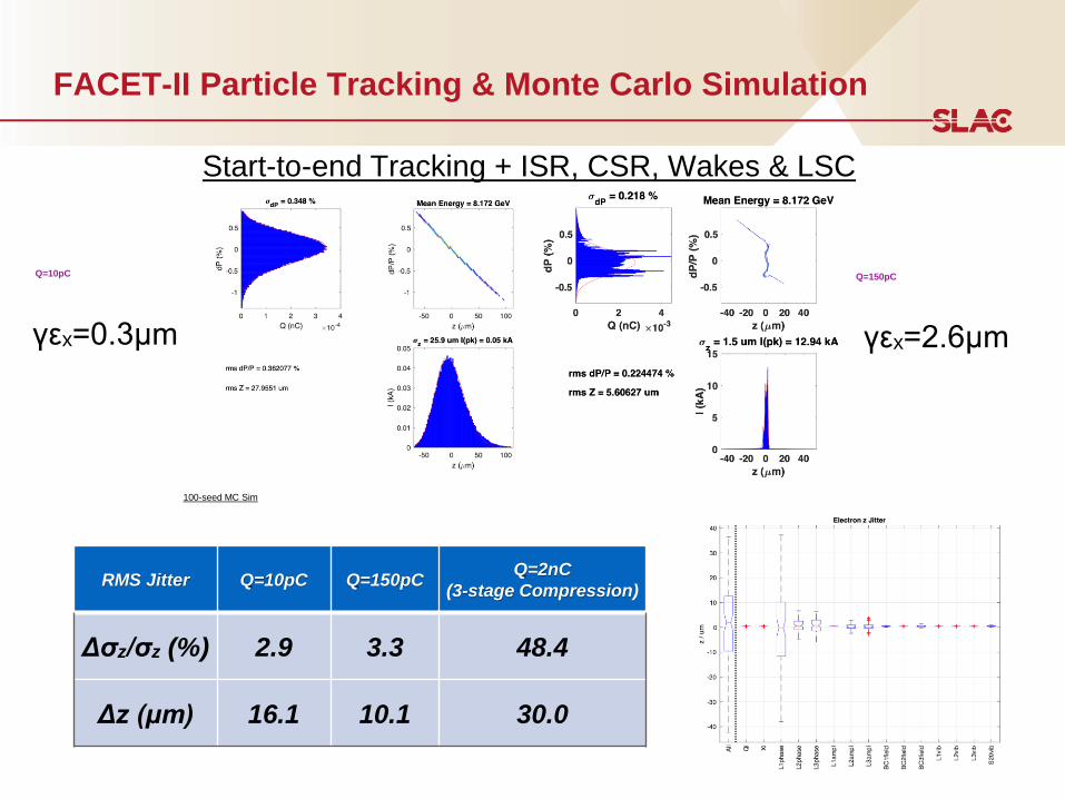
FACET-II Particle Tracking & Monte Carlo Simulation
Q=10pC Q=150pC
γεx=0.3μm γεx=2.6μm
RMS Jitter Q=10pC Q=150pCQ=2nC
(3-stage Compression)
Δσz/σz (%) 2.9 3.3 48.4
Δz (μm) 16.1 10.1 30.0
100-seed MC Sim
Start-to-end Tracking + ISR, CSR, Wakes & LSC
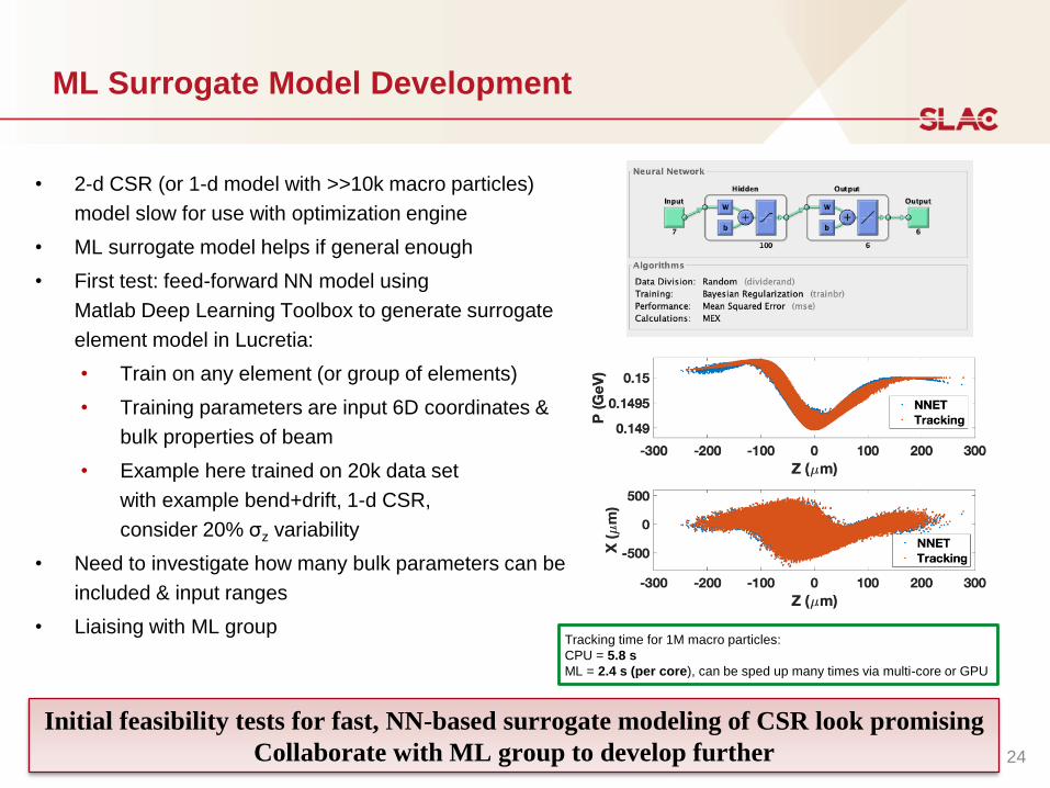
ML Surrogate Model Development
• 2-d CSR (or 1-d model with >>10k macro particles)
model slow for use with optimization engine
• ML surrogate model helps if general enough
• First test: feed-forward NN model using
Matlab Deep Learning Toolbox to generate surrogate
element model in Lucretia:
• Train on any element (or group of elements)
• Training parameters are input 6D coordinates &
bulk properties of beam
• Example here trained on 20k data set
with example bend+drift, 1-d CSR,
consider 20% σz variability
• Need to investigate how many bulk parameters can be
included & input ranges
• Liaising with ML groupTracking time for 1M macro particles:
CPU = 5.8 s
ML = 2.4 s (per core), can be sped up many times via multi-core or GPU
Initial feasibility tests for fast, NN-based surrogate modeling of CSR look promising
Collaborate with ML group to develop further 24
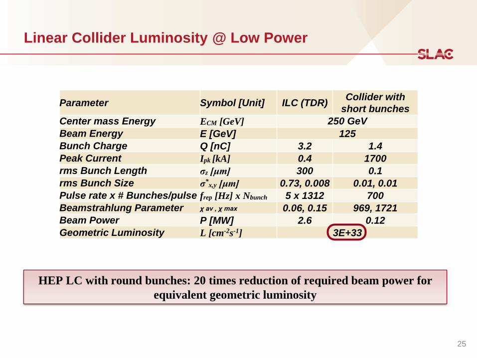
Linear Collider Luminosity @ Low Power
Parameter Symbol [Unit] ILC (TDR)Collider with
short bunches
Center mass Energy ECM [GeV] 250 GeV
Beam Energy E [GeV] 125
Bunch Charge Q [nC] 3.2 1.4
Peak Current Ipk [kA] 0.4 1700
rms Bunch Length σz [μm] 300 0.1
rms Bunch Size σ*x,y [μm] 0.73, 0.008 0.01, 0.01
Pulse rate x # Bunches/pulse frep [Hz] x Nbunch 5 x 1312 700
Beamstrahlung Parameter χ av , χ max 0.06, 0.15 969, 1721
Beam Power P [MW] 2.6 0.12
Geometric Luminosity L [cm-2s-1] 3E+33
HEP LC with round bunches: 20 times reduction of required beam power for
equivalent geometric luminosity
25
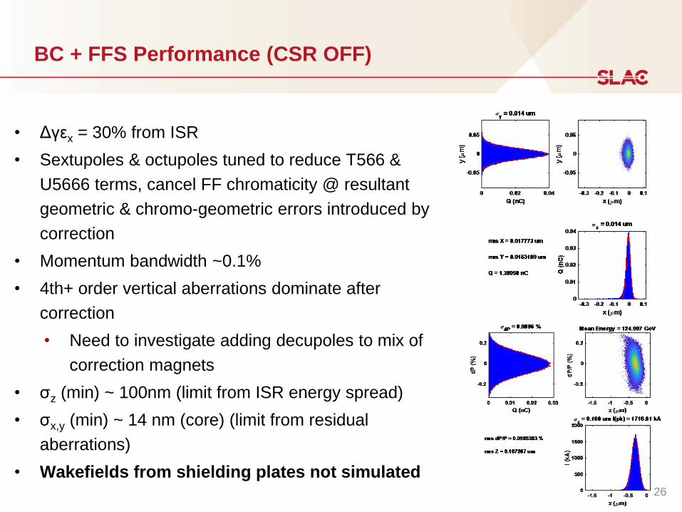
BC + FFS Performance (CSR OFF)
• Δγεx = 30% from ISR
• Sextupoles & octupoles tuned to reduce T566 &
U5666 terms, cancel FF chromaticity @ resultant
geometric & chromo-geometric errors introduced by
correction
• Momentum bandwidth ~0.1%
• 4th+ order vertical aberrations dominate after
correction
• Need to investigate adding decupoles to mix of
correction magnets
• σz (min) ~ 100nm (limit from ISR energy spread)
• σx,y (min) ~ 14 nm (core) (limit from residual
aberrations)
• Wakefields from shielding plates not simulated26
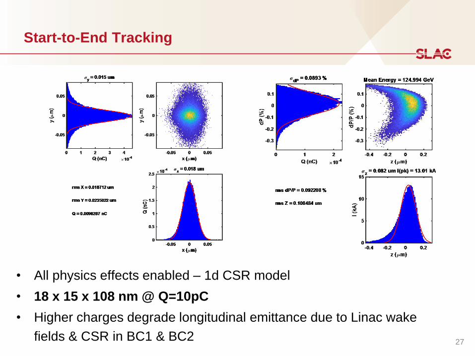
Start-to-End Tracking
• All physics effects enabled – 1d CSR model
• 18 x 15 x 108 nm @ Q=10pC
• Higher charges degrade longitudinal emittance due to Linac wake
fields & CSR in BC1 & BC227
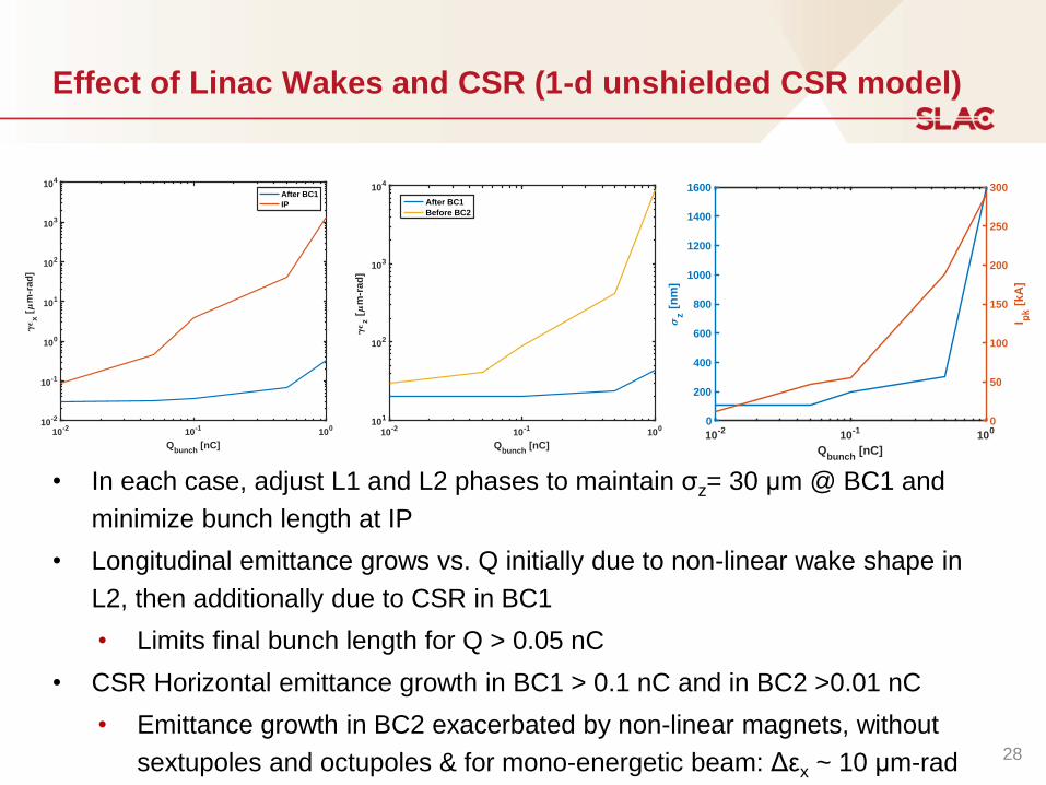
Effect of Linac Wakes and CSR (1-d unshielded CSR model)
• In each case, adjust L1 and L2 phases to maintain σz= 30 μm @ BC1 and
minimize bunch length at IP
• Longitudinal emittance grows vs. Q initially due to non-linear wake shape in
L2, then additionally due to CSR in BC1
• Limits final bunch length for Q > 0.05 nC
• CSR Horizontal emittance growth in BC1 > 0.1 nC and in BC2 >0.01 nC
• Emittance growth in BC2 exacerbated by non-linear magnets, without
sextupoles and octupoles & for mono-energetic beam: Δεx ~ 10 μm-rad
10-2
10-1
100
Qbunch
[nC]
10-2
10-1
100
101
102
103
104
x [
m-r
ad
]
After BC1
IP
10-2
10-1
100
Qbunch
[nC]
101
102
103
104
z [
m-r
ad
]
After BC1
Before BC2
10-2
10-1
100
Qbunch
[nC]
0
200
400
600
800
1000
1200
1400
1600
z [
nm
]
0
50
100
150
200
250
300
I pk [
kA
]
28
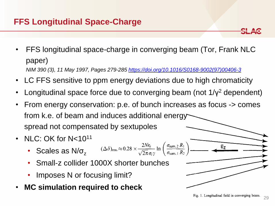
FFS Longitudinal Space-Charge
• FFS longitudinal space-charge in converging beam (Tor, Frank NLC
paper)NIM 390 (3), 11 May 1997, Pages 279-285 https://doi.org/10.1016/S0168-9002(97)00406-3
• LC FFS sensitive to ppm energy deviations due to high chromaticity
• Longitudinal space force due to converging beam (not 1/γ2 dependent)
• From energy conservation: p.e. of bunch increases as focus -> comes
from k.e. of beam and induces additional energy
spread not compensated by sextupoles
• NLC: OK for N<1011
• Scales as N/σz
• Small-z collider 1000X shorter bunches
• Imposes N or focusing limit?
• MC simulation required to check
29
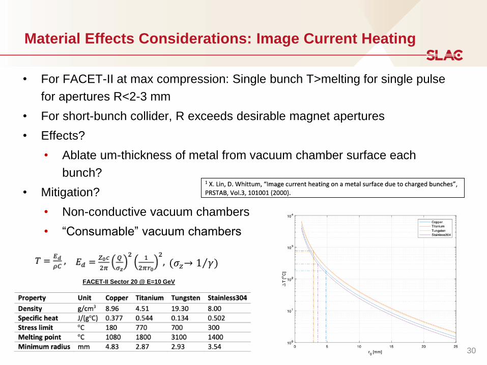
Material Effects Considerations: Image Current Heating
• For FACET-II at max compression: Single bunch T>melting for single pulse
for apertures R<2-3 mm
• For short-bunch collider, R exceeds desirable magnet apertures
• Effects?
• Ablate um-thickness of metal from vacuum chamber surface each
bunch?
• Mitigation?
• Non-conductive vacuum chambers
• “Consumable” vacuum chambers
FACET-II Sector 20 @ E=10 GeV
30
(𝜎𝑧→ Τ1 𝛾)


![The Bottleneck Effect as an inescapable constraint in ...demines.del.auth.gr/files/summerschool/Catasso_The...TP/VP t z t i nicht da]]]]]. • Seeming V3-configurations, e.g.German](https://static.fdocument.org/doc/165x107/5f7364a6bd12cf5efd731f8e/the-bottleneck-effect-as-an-inescapable-constraint-in-tpvp-t-z-t-i-nicht.jpg)