Part VII Radiographic Inspection - ase.uc.edupnagy/ClassNotes/AEEM7027 Nondestructive Testin… ·...
25
Part VII Radiographic Inspection
Transcript of Part VII Radiographic Inspection - ase.uc.edupnagy/ClassNotes/AEEM7027 Nondestructive Testin… ·...
Part VII
Radiographic Inspection
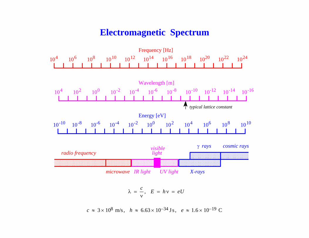
Electromagnetic Spectrum
microwave IR light
cosmic rays
X-rays
γ rays
UV light
visiblelightradio frequency
Frequency [Hz]
10 1081064 10 1014101210 10 1020101816 1022 1024
Energy [eV]
10 10-610-8-10 10 10010-2-4 10 1061042 108 1010
Wavelength [m]
10 1001024 10 10-610-4-2 10 10-1210-10-8 10-14 10-16
typical lattice constant
cλ =
ν, E h eU= ν =
83 10 m/sc ≈ × , 346.63 10 J sh −≈ × , 191.6 10 Ce −≈ ×
Microwave Techniques
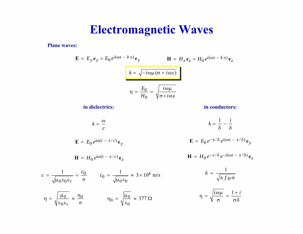
Electromagnetic WavesPlane waves:
in dielectrics:
( )0 i t k xy y yE E e ω −= =E e e ( )0
i t k xz z zH H e ω −= =H e e
0
0
E iH i
ωμη = =
σ+ ωε
( )k i i= − ωμ σ + ωε
in conductors:
/ ( / )0 x i t x yE e e− δ ω − δ=E e
/ ( / )0
x i t xzH e e− δ − ω − δ=H e
1 ik = −δ δ
1i iωμ +η = =
σ σδ
1f
δ =π μ σ
00
0377μ
η = ≈ Ωε
0 0
0 r nμ η
η = ≈ε ε
( / )0 i t x c yE e ω −=E e
( / )0
i t x czH e ω −=H e
kcω
=
0
0 0
1
r
ccn
= =μ ε ε
80
0 0
1 3 10 m/sc = ≈ ×μ ε
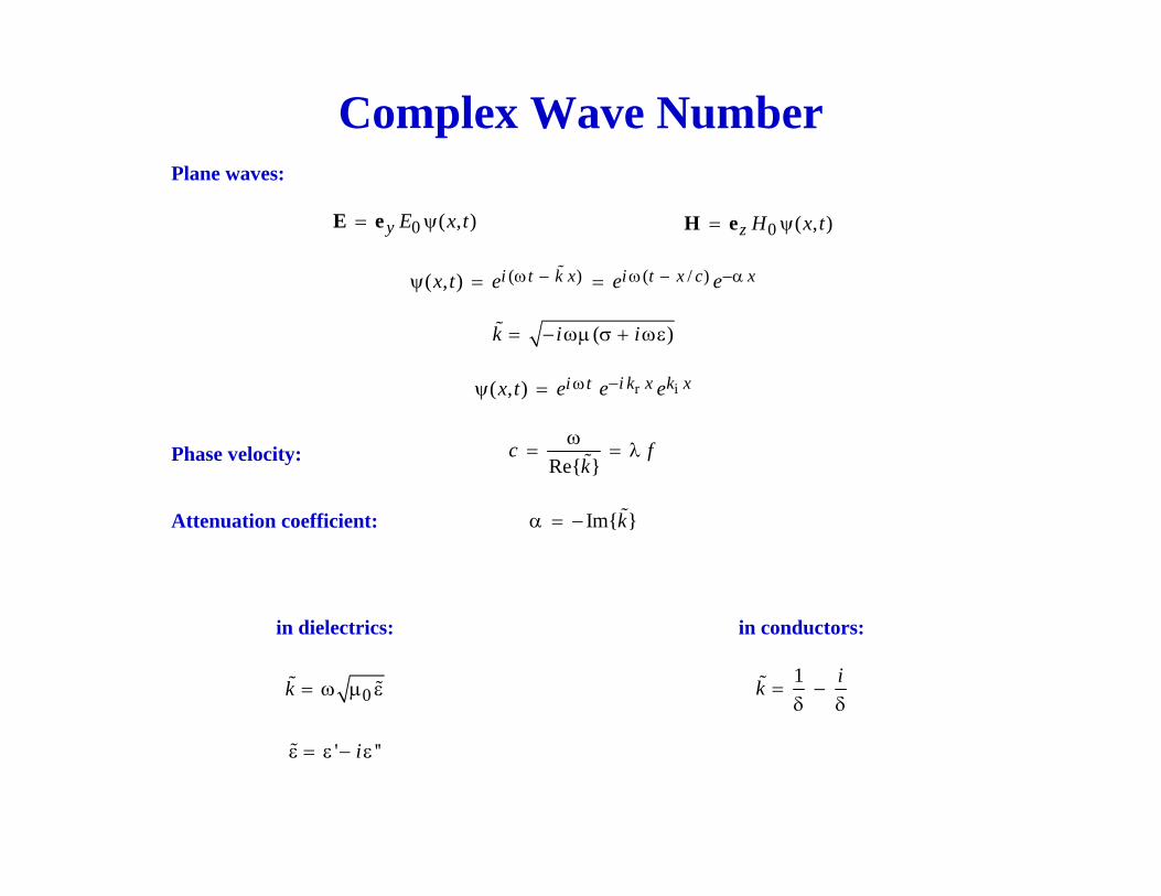
Complex Wave NumberPlane waves:
0 ( , )y E x t= ψE e 0 ( , )z H x t= ψH e
( )k i i= − ωμ σ + ωε
in dielectrics: in conductors:
1 ik = −δ δ0k = ω μ ε
( ) ( / )( , ) i t k x i t x c xx t e e eω − ω − −αψ = =
r i( , ) i k x k xi tx t e e e−ωψ =
Re{ }c f
kω
= = λPhase velocity:
Im{ }kα = −Attenuation coefficient:
' ''iε = ε − ε
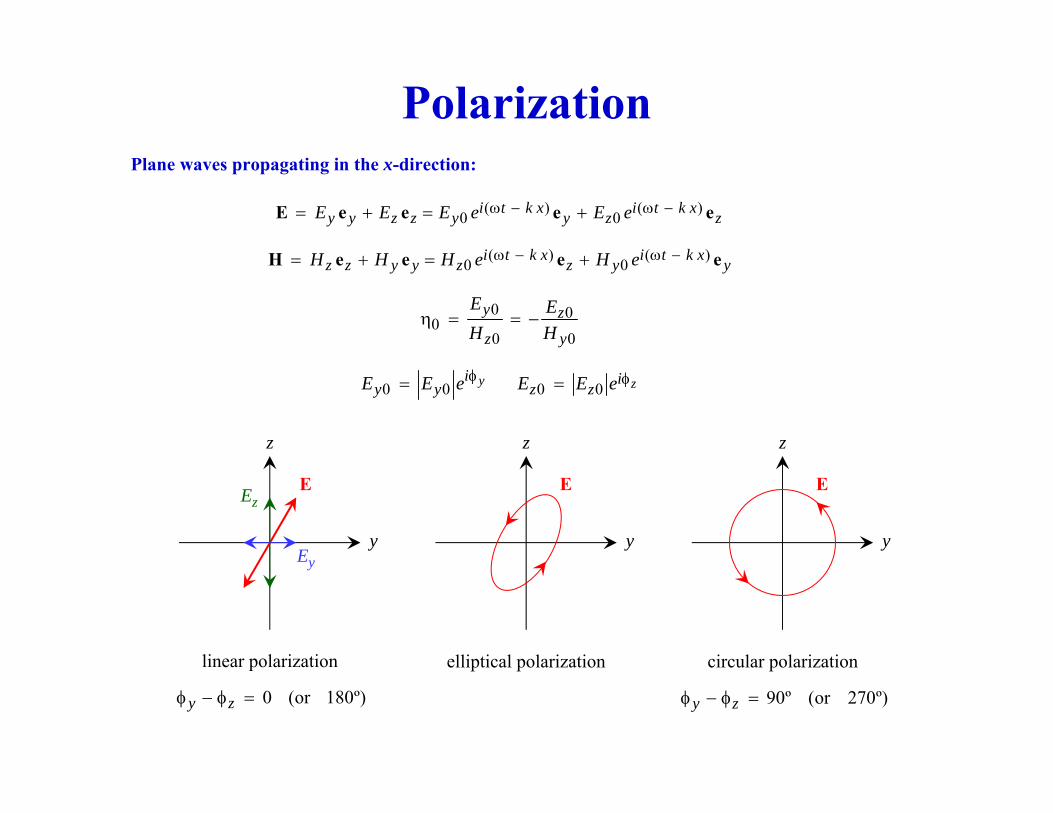
PolarizationPlane waves propagating in the x-direction:
( ) ( )0 0i t k x i t k xy y z z y y z zE E E e E eω − ω −= + = +E e e e e
( ) ( )0 0i t k x i t k xz z y y z z y yH H H e H eω − ω −= + = +H e e e e
0 00
0 0
y z
z y
E EH H
η = = −
0 0 0 0y zi iy y z zE E e E E eφ φ= =
y
z
y
z
y
z
Ey
EzE
0 (or 180º)y zφ − φ =
linear polarization elliptical polarization
90º (or 270º)y zφ − φ =
circular polarization
E E
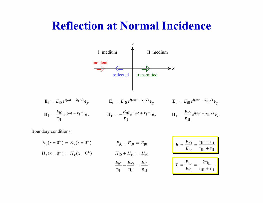
Reflection at Normal Incidence
x
y
incident
reflected transmitted
I( )i i0
i t k xyE e ω −=E e
Ii0 ( )i
Ii t k x
zE e ω −=η
H e
I( )r r0
i t k xyE e ω +=E e
Ir0 ( )r
Ii t k x
zE e ω += −η
H e
II( )t t0
i t k xyE e ω −=E e
IIt0 ( )t
IIi t k x
zE e ω −=η
H e
I medium II medium
Boundary conditions:
( 0 ) ( 0 )y yE x E x− += = = i0 r0 t0E E E+ =
( 0 ) ( 0 )z zH x H x− += = = i0 r0 t0H H H+ =
i0 r0 t0
I I II
E E E− =
η η η
r0 II Ii0 II I
ERE
η − η= =
η + η
t0 IIi0 II I
2ETE
η= =
η + η
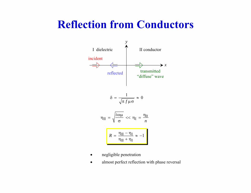
Reflection from Conductors
x
y
incident
reflected transmitted“diffuse” wave
I dielectric II conductor
1 0f
δ = ≈π μσ
0II I
in
ηωμη = << η =
σ
II III I
1R η − η= ≈ −
η + η
• negligible penetration
• almost perfect reflection with phase reversal
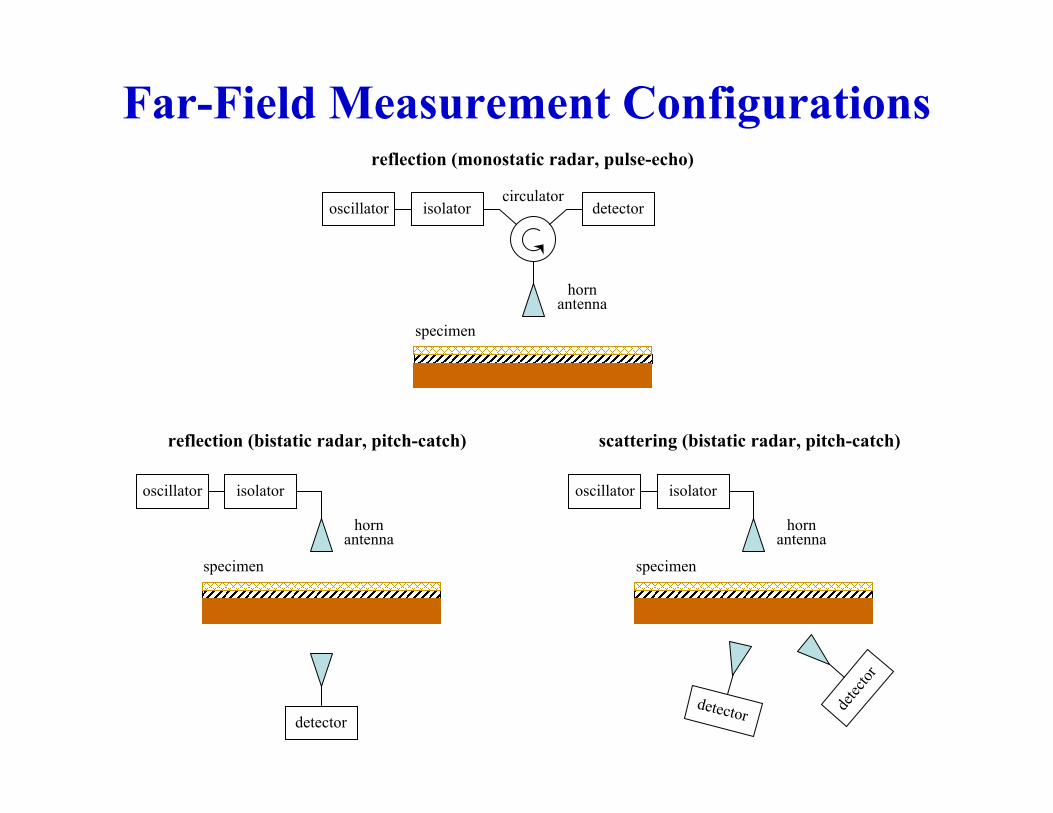
Far-Field Measurement Configurations
detectorisolatoroscillatorcirculator
hornantenna
specimen
reflection (monostatic radar, pulse-echo)
detector
isolatoroscillator
hornantenna
specimen
reflection (bistatic radar, pitch-catch) scattering (bistatic radar, pitch-catch)
isolatoroscillator
hornantenna
specimen
detector detec
tor
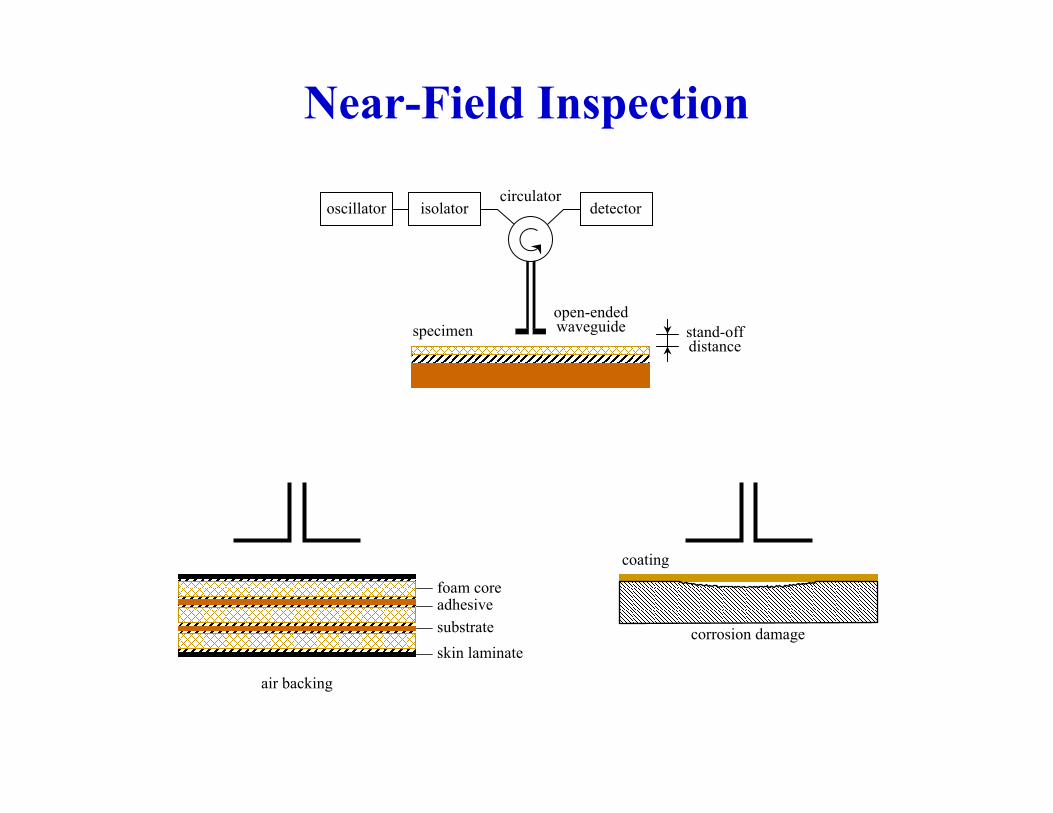
Near-Field Inspection
detectorisolatoroscillatorcirculator
open-endedwaveguidespecimen stand-off
distance
air backing
foam coreadhesivesubstrateskin laminate
corrosion damage
coating
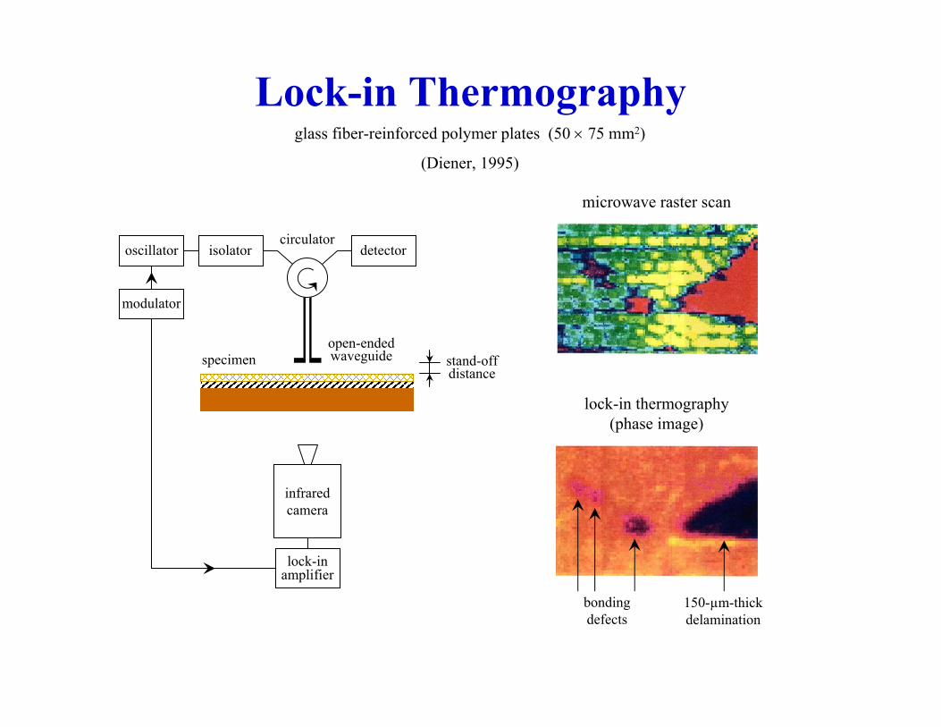
Lock-in Thermographyglass fiber-reinforced polymer plates (50 × 75 mm2)
(Diener, 1995)
detectorisolatoroscillatorcirculator
open-endedwaveguidespecimen stand-off
distance
infraredcamera
lock-inamplifier
modulator
microwave raster scan
lock-in thermography(phase image)
150-µm-thickdelamination
bondingdefects
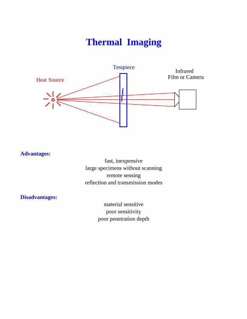
Thermal Imaging
Heat Source
Testpiece
Film or CameraInfrared
Advantages: fast, inexpensive
large specimens without scanning remote sensing
reflection and transmission modes
Disadvantages: material sensitive poor sensitivity
poor penetration depth
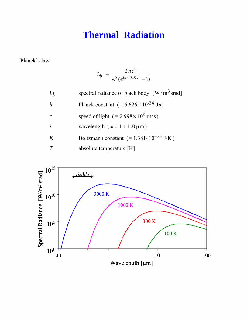
Thermal Radiation
Planck’s law 2
5 /2
( 1)b hc KThcL
e λ=λ −
Lb spectral radiance of black body 3[W / m srad]
h Planck constant ( -34= 6.626 10 Js× )
c speed of light ( 8= 2.998 10 m/s× )
λ wavelength ( 0.1 100 m≈ ÷ μ )
K Boltzmann constant ( 23= 1.381 10 J/K−× )
T absolute temperature [K]
0
5
10
15
0.1 1 10 100Wavelength [µm]
Spec
tral R
adia
nce
[W/m
3sr
ad]
1000 K
300 K
3000 K
100 K
visible10
10
10
100
5
10
15
0.1 1 10 100Wavelength [µm]
Spec
tral R
adia
nce
[W/m
3sr
ad]
1000 K
300 K
3000 K
100 K
visible10
10
10
10
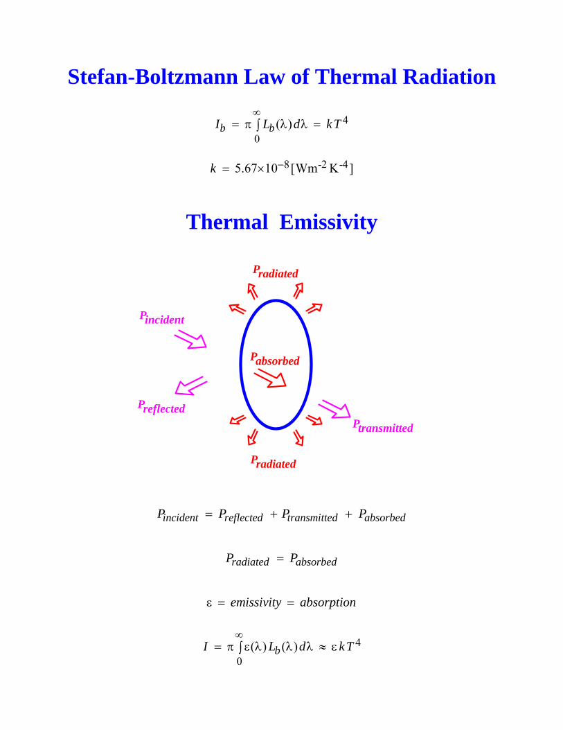
Stefan-Boltzmann Law of Thermal Radiation
4
0( )b bI L d kT
∞= π λ λ =∫
8 -2 -45.67 10 [Wm K ]k −= ×
Thermal Emissivity
Pincident
Ptransmitted
Preflected
Pabsorbed
Pradiated
Pradiated
incident reflected transmitted absorbedP P P P= + +
radiated absorbedP P=
emissivity absorptionε = =
4
0( ) ( )bI L d kT
∞= π ε λ λ λ ≈ ε∫
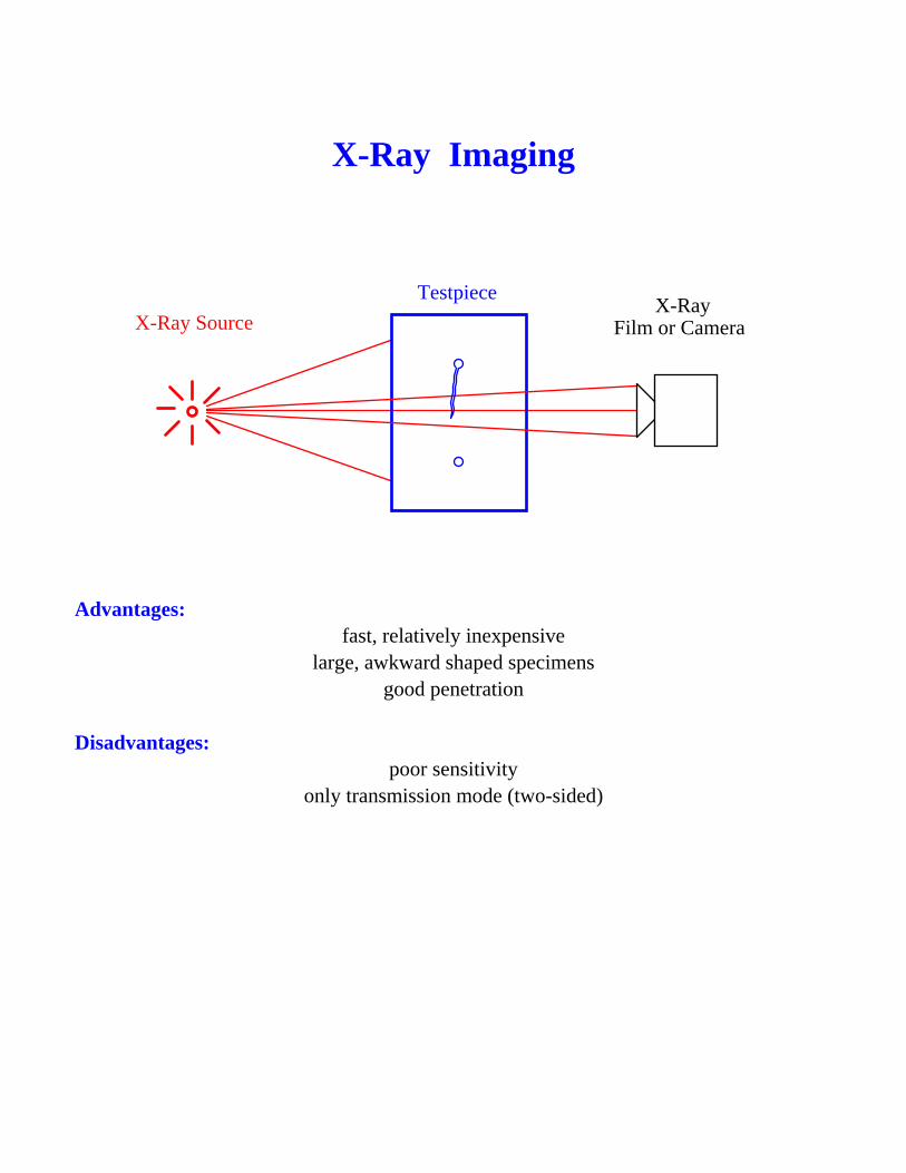
X-Ray Imaging
X-Ray SourceTestpiece
Film or CameraX-Ray
Advantages:
fast, relatively inexpensive large, awkward shaped specimens
good penetration
Disadvantages: poor sensitivity
only transmission mode (two-sided)
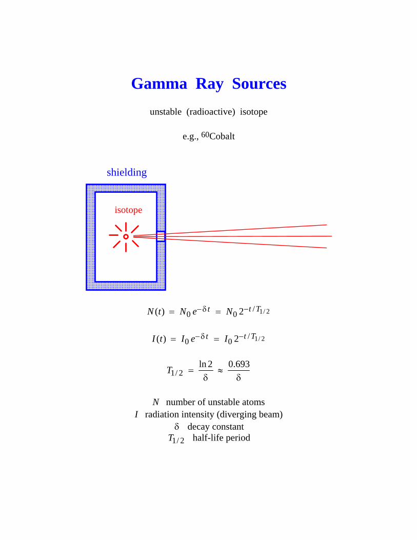
Gamma Ray Sources
unstable (radioactive) isotope
e.g., 60Cobalt
isotope
shielding
1/ 2/0 0( ) 2 t TtN t N e N −− δ= =
1/ 2/
0 0( ) 2 t TtI t I e I −− δ= =
1/ 2ln 2 0.693T = ≈δ δ
N number of unstable atoms
I radiation intensity (diverging beam) δ decay constant
1/ 2T half-life period
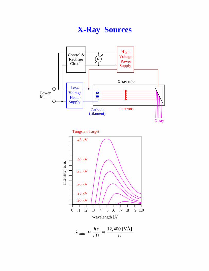
X-Ray Sources
Cathode(filament)
X-ray
electrons
High-VoltagePower
Supply
Low-VoltageHeater
Supply
PowerMains
Control &RectifierCircuit
V_
X-ray tube
Inte
nsity
[a. u
.]
0 .1 .2 .3 .4 .5 .6 .7 .8 .9 1.0
Wavelength [Å]
20 kV
25 kV
30 kV
35 kV
40 kV
45 kV
Tungsten Target
min12,400 [VÅ]h c
eU Uλ ≈ ≈
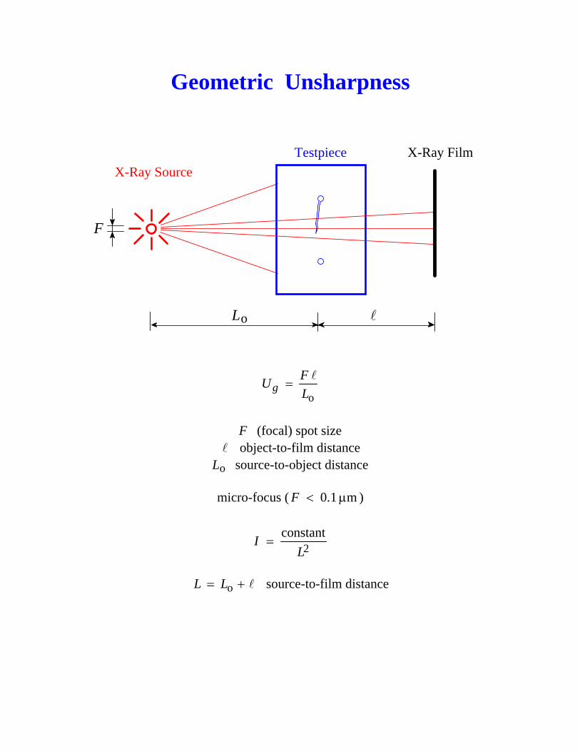
Geometric Unsharpness
X-Ray SourceTestpiece X-Ray Film
F
Lo
og
FUL
=
F (focal) spot size
object-to-film distance Lo source-to-object distance
micro-focus ( 0.1 mF < μ )
2constantI
L=
oL L= + source-to-film distance
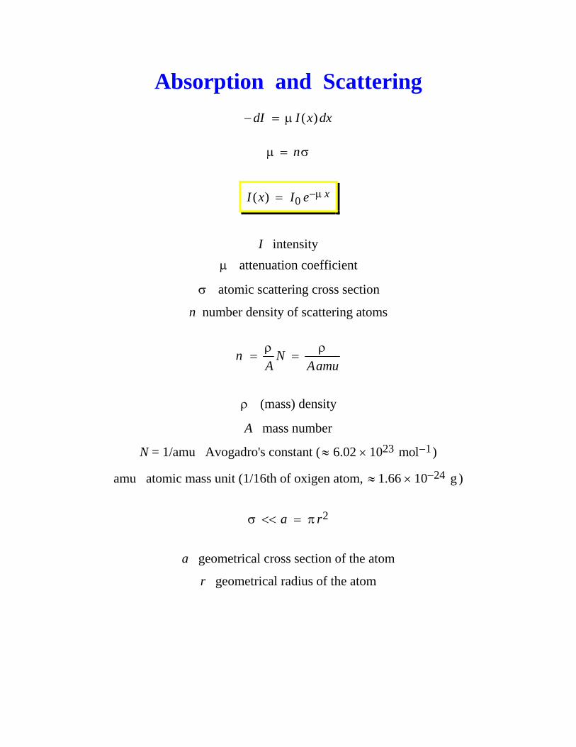
Absorption and Scattering
( )dI I x dx− = μ nμ = σ
0( ) xI x I e−μ=
I intensity μ attenuation coefficient
σ atomic scattering cross section
n number density of scattering atoms
n NA Aamuρ ρ
= =
ρ (mass) density
A mass number
N = 1/amu Avogadro's constant ( 23 16.02 10 mol−≈ × )
amu atomic mass unit (1/16th of oxigen atom, 241.66 10 g−≈ × )
2a rσ << = π
a geometrical cross section of the atom
r geometrical radius of the atom
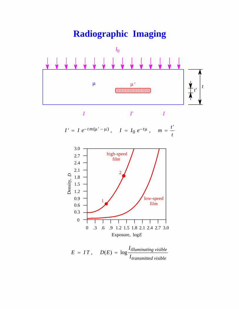
Radiographic Imaging
t'tμ μ '
I0
I I' I
( ' )' t mI I e− μ − μ= , 0 tI I e− μ= , 'tmt
=
Den
sity
, D
0 .3 .6 .9 1.2 1.5 1.8 2.1 2.4 2.7 3.0
3.02.72.42.11.81.51.20.90.60.3
0
1
2
high-speedfilm
low-speedfilm
Exposure, log E
E I T= , ( ) log illuminating visible
transmitted visible
ID E
I=
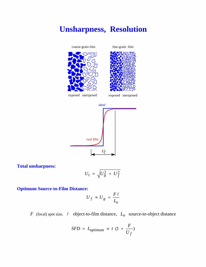
Unsharpness, Resolution
exposed unexposed exposed unexposed
coarse-grain film fine-grain film
Uf
ideal
real film
Total unsharpness: 2 2t g fU U U= +
Optimum Source-to-Film Distance:
of g
FU UL
≈ =
F (focal) spot size, object-to-film distance, Lo source-to-object distance
(1 )optimumf
FSFD L tU
= ≈ +
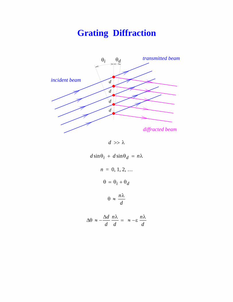
Grating Diffraction
diffracted beam
incident beam
θi θd
d
d
d
d
transmitted beam
d >> λ
sin sini dd d nθ + θ = λ
n = 0, 1, 2, … i dθ = θ + θ ndλ
θ ≈
d n n
d d dΔ λ λ
Δθ ≈ − = ≈ −ε
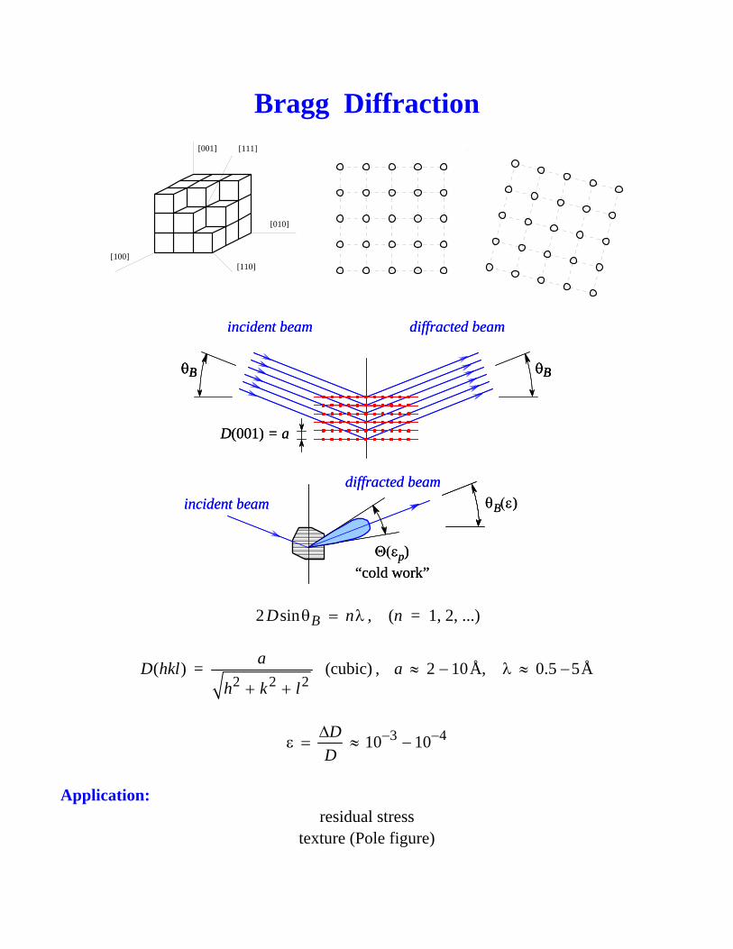
Bragg Diffraction
[100]
[010]
[001]
[110]
[111]
incident beam diffracted beam
D(001) = a
θB θB
incident beamdiffracted beam
Θ(εp)“cold work”
θB(ε)
incident beam diffracted beam
D(001) = a
θBθB θBθB
incident beamdiffracted beam
Θ(εp)“cold work”
θB(ε)
2 sin BD nθ = λ , (n = 1, 2, ...)
2 2 2( ) = (cubic)aD hkl
h k l+ +, 2 10Å, 0.5 5Åa ≈ − λ ≈ −
3 410 10D
D− −Δ
ε = ≈ −
Application:
residual stress texture (Pole figure)
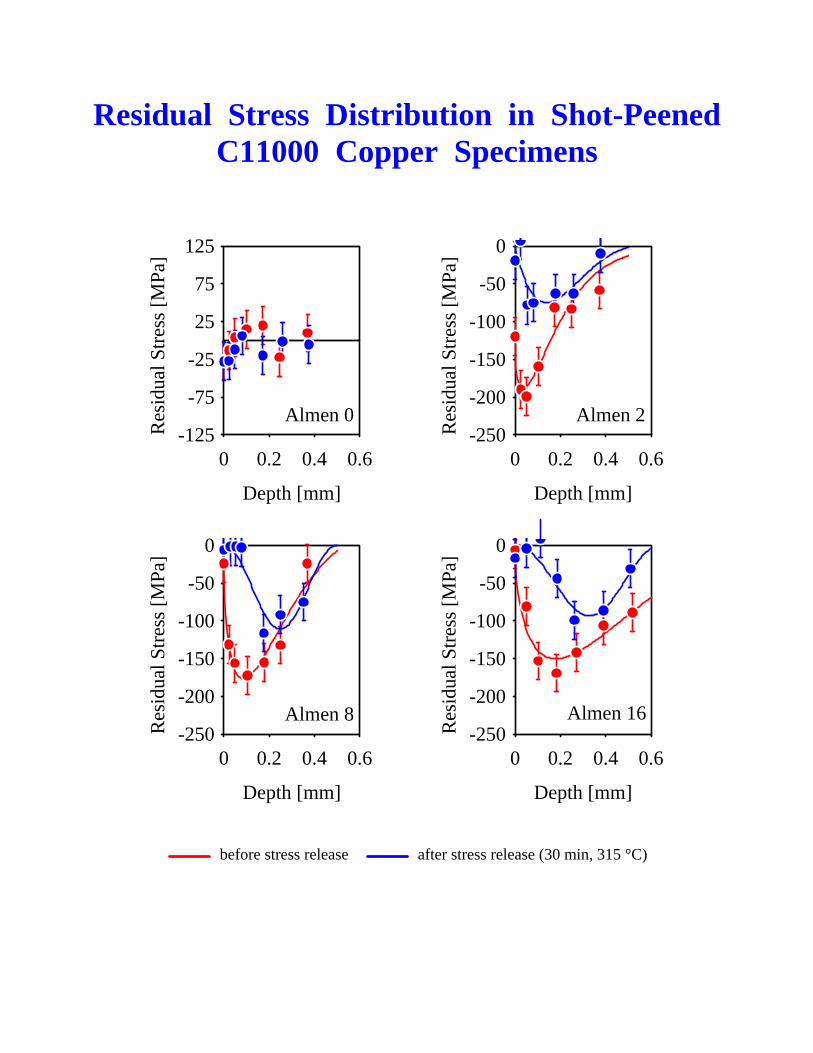
Residual Stress Distribution in Shot-Peened C11000 Copper Specimens
Depth [mm]
Res
idua
l Stre
ss [M
Pa]
-125
-75
-25
25
75
125
0 0.2 0.4 0.6
Almen 0
Depth [mm]
Res
idua
l Stre
ss [M
Pa]
-250
-200
-150
-100
-50
0
0 0.2 0.4 0.6
Almen 2
Depth [mm]
Res
idua
l Stre
ss [M
Pa]
-250
-200
-150
-100
-50
0
0 0.2 0.4 0.6
Almen 8
Depth [mm]
Res
idua
l Stre
ss [M
Pa]
-250
-200
-150
-100
-50
0
0 0.2 0.4 0.6
Almen 16
before stress release after stress release (30 min, 315 °C)
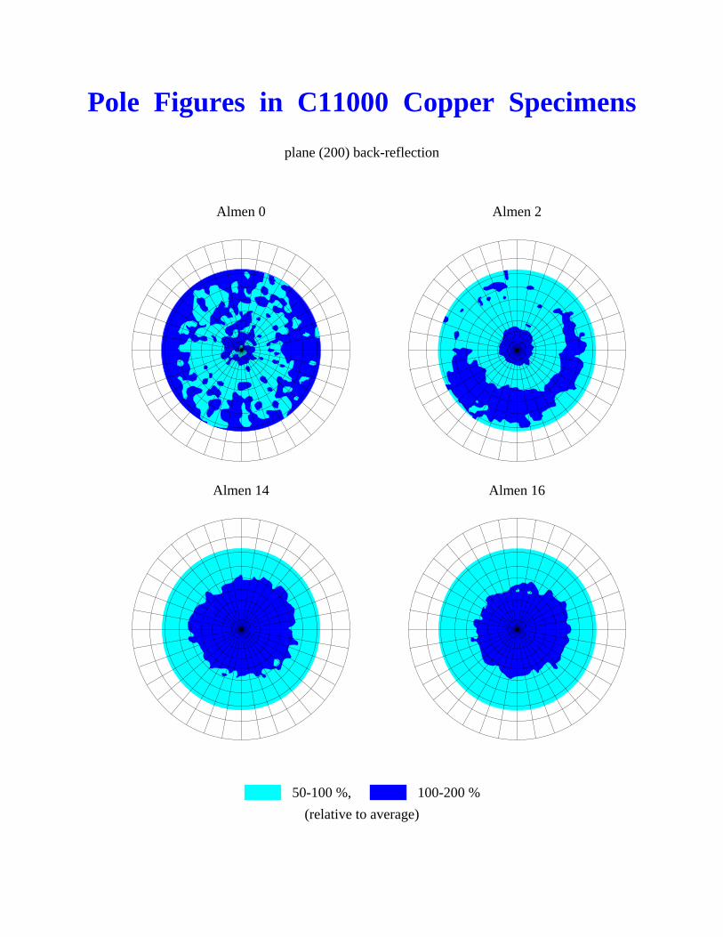
Pole Figures in C11000 Copper Specimens
plane (200) back-reflection
Almen 0 Almen 2
Almen 14 Almen 16
50-100 %, 100-200 % (relative to average)
![Paper30 Nondestructive Examination of Turbine and ... · PDF fileA fracture-mechanics safety analysis is then carried out on the basis of the obtained test re- ... [ 1,2,3 ]. In spite](https://static.fdocument.org/doc/165x107/5a78cb367f8b9a70238c856c/paper30-nondestructive-examination-of-turbine-and-fracture-mechanics-safety.jpg)