ASTRA simulations of the slice longitudinal momentum ... Leninskie Gory, Moscow, 119992, Russian...
12
ASTRA simulations of the slice longitudinal momentum spread along the beamline for PITZ Orlova Ksenia Lomonosov Moscow State University GSP-2, Leninskie Gory, Moscow, 119992, Russian Federation Email: [email protected] The Photo Injector Test Facility at DESY Zeuthen (PITZ) was built to produce and optimize an intense electron beam with a very small transverse emittance (below 1.4 mm mrad) and rather small longitudinal emittance for Free-Electron-Lasers (FELs). In order to reach the desired high electron peak current, the pulse length of a low-emittance electron bunch generated from the photocathode rf gun is compressed in the linear accelerator by magnetic bunch compressors (BCs). In this case the slice parameters of the electron bunch are of great importance. The properties of the bunch are defined in the gun and can be analyzed at PITZ. This report is devoted to investigations with ASTRA simulations of the longitudinal slice momentum spread along the PITZ beamline for different charges, gun and booster phases. 1. Introduction 1.1 Overview of PITZ The main goal of the Photo Injector Test Facility at DESY Zeuthen (PITZ) is the test and optimization of photo injectors for Free-Electron Lasers (FELs) and linear colliders like FLASH and XFEL in Hamburg. The main challenge is to produce an intense electron beam with a very small transverse emittance and rather small longitudinal emittance. An overview of the PITZ is schematically shown in Fig. 1 [1]. Fig. 1: Scheme of the Photo Injector Test Facility at DESY Zeuthen 1
Transcript of ASTRA simulations of the slice longitudinal momentum ... Leninskie Gory, Moscow, 119992, Russian...
ASTRA simulations of the slice longitudinal momentum spread along the beamline for PITZ
Orlova Ksenia Lomonosov Moscow State University
GSP-2, Leninskie Gory, Moscow, 119992, Russian Federation Email: [email protected]
The Photo Injector Test Facility at DESY Zeuthen (PITZ) was built to produce and optimize an intense electron beam with a very small transverse emittance (below 1.4 mm mrad) and rather small longitudinal emittance for Free-Electron-Lasers (FELs). In order to reach the desired high electron peak current, the pulse length of a low-emittance electron bunch generated from the photocathode rf gun is compressed in the linear accelerator by magnetic bunch compressors (BCs). In this case the slice parameters of the electron bunch are of great importance. The properties of the bunch are defined in the gun and can be analyzed at PITZ. This report is devoted to investigations with ASTRA simulations of the longitudinal slice momentum spread along the PITZ beamline for different charges, gun and booster phases.
1. Introduction
1.1 Overview of PITZ
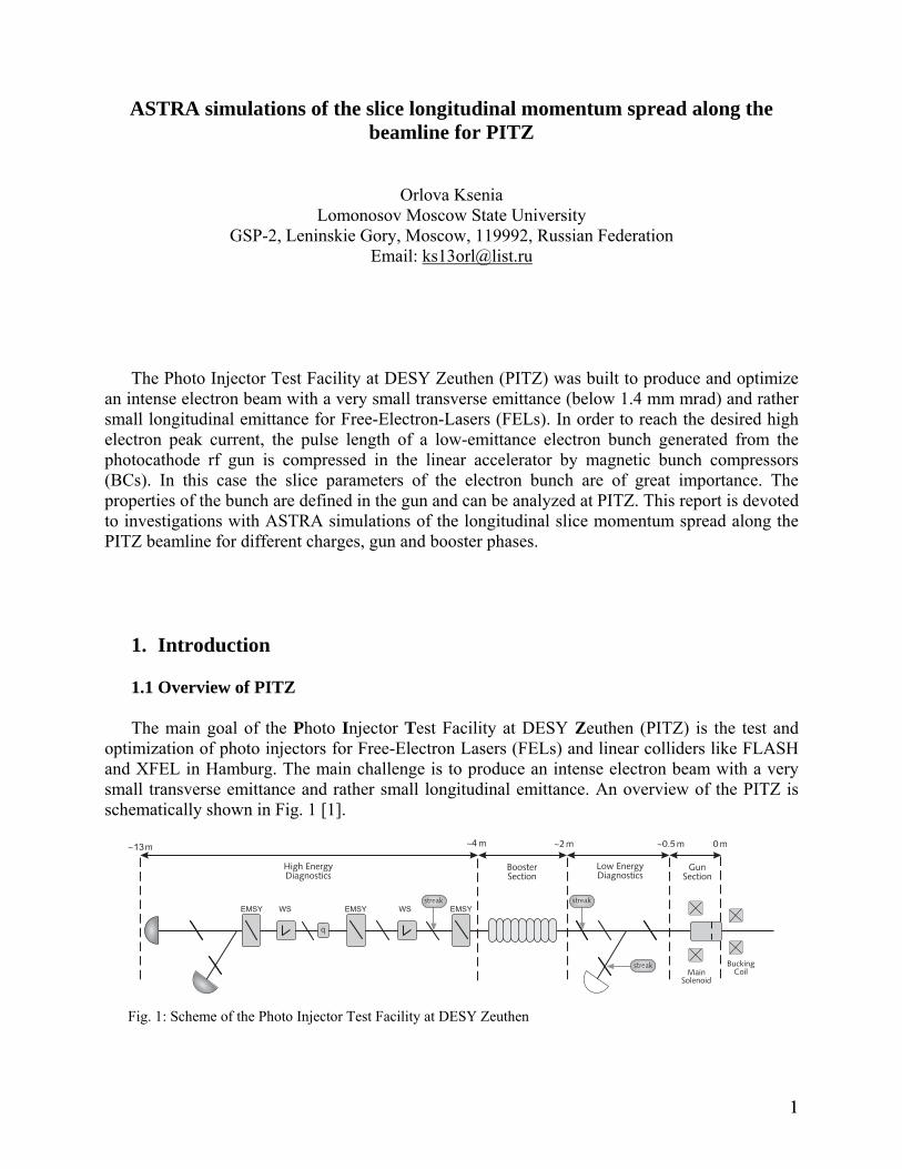
The main goal of the Photo Injector Test Facility at DESY Zeuthen (PITZ) is the test and optimization of photo injectors for Free-Electron Lasers (FELs) and linear colliders like FLASH and XFEL in Hamburg. The main challenge is to produce an intense electron beam with a very small transverse emittance and rather small longitudinal emittance. An overview of the PITZ is schematically shown in Fig. 1 [1].
Fig. 1: Scheme of the Photo Injector Test Facility at DESY Zeuthen
11
A pulsed laser beam (wavelength 262nm, pulse energy ~22μJ) hits a Cs2Te photocathode and due to the photoelectric effect electron bunches with a similar structure are emitted. The electrons, leaving the cathode, are immediately accelerated by an electromagnetic standing wave with frequency 1.3 GHz. The electron bunches leaving the gun cavity reach energies of 5-6 MeV.
The 1.5 cell copper gun cavity is surrounded by a pair of solenoid magnets, which are called main and bucking solenoids. The main solenoid serves as an electronic lens, it compensates space charge effects by focusing the beam transversally. This focus has to be adjusted depending on the beam energy and bunch charge. The task of the bucking solenoid is to compensate the magnetic field at the cathode surface. A copper booster cavity is used after the rf gun for further beam acceleration in order to study the emittance conservation principle.
The PITZ facility contains a lot of diagnostic devices to analyse the beam and to understand the beam dynamics in more detail.
1.2 ASTRA
ASTRA (A Space Charge Tracking Algorithm) [2] was used for all the simulations presented in this report. It was developed to track the bunch along the beamline under the influence of external and internal fields and get a better understanding of the beam dynamics.
Different cavities, solenoids and quadruples can be added in the simulations. By default the energy gain of each cavity is scanned prior to the tracking of the reference particle. The user-defined phase of the field refers than to the phase of the maximum energy. This is called auto phasing. All the simulations in this report were made with this procedure. In all the work the phase of the maximum energy gain is referred to as zero.
1.3 Motivation
In order to reach the desired high electron peak current suitable for a free-electron laser (FEL) in the X-ray regime, the pulse length of a low-emittance electron bunch generated from the photocathode rf gun is compressed in the linear accelerator by magnetic bunch compressors (BCs). An electron bunch, which contains energy modulations, will induces density modulations when passing the bunch compressor. Energy modulations can be caused by small density modulations of the electron beam from the photocathode due to Longitudinal Space Charge, Coherent Synchrotron Radiation, geometrical wakefields and so on [3-4]. Since the compressor introduces path length dependence on energy, the induced energy modulations are converted to additional density modulations which can be much larger than the initial density modulations. This amplification process is accompanied by a growth of energy modulations and a possible growth of emittance if significant energy modulations are induced in a dispersive region such as the chicane. Thus, the instability can be harmful to the FEL performance, which depends critically on the high quality of the electron bunch.
In [3] it was estimated that the gain in density modulation is:
G≈ρind
ρi,
where indρ is the amplitude of the induced density modulation and iρ is the initial one. The gain in density modulation can be described as a function of the rms uncorrelated energy spread before compression Eσ (in units of rest energy) because . For the very small uncorrelated energy spread generated from a photocathode rf gun, the peak overall gain can
)exp(~ 2EG σ−
22
become very large during bunch compression and can even significantly amplify the electron shot noise. The only effective way to suppress the large gain is to increase the uncorrelated energy spread before compressing the bunch.
In this report the longitudinal correlated momentum spread is investigated for the PITZ for different beam positions, different phases of the gun and booster cavities and for different bunch charges.
2. Slice momentum spread of the bunch and definition of the number of slices
In order to analyze the correlated momentum spread of the bunch it was divided into
longitudinal slices. There are several ways to do this. The bunch can be divided: into the same number of slices, into the same length of the slice, by the same number of particles in the slice.
In the first two cases bad statistics is expected at the tails and good statistics in the middle of the bunch. If the bunch contains the same number of particles the length of the slice in the tails will strongly differ from the middle of the bunch. In this work it was decided to divide the bunch in the same number of slices because in this case it is easier to compare the momentum spread for different beam positions and different phases of the gun and booster cavities.
Another problem was to understand how many slices are necessary to determine the correlated momentum spread. If we divide the bunch into the large number of slices the length of the slice is reduced and the results is closer to the correlated value but in this case the statistics gets worse. Fig. 2 shows the longitudinal phase space of the bunch, where the vertical axis is the longitudinal momentum spread and the horizontal axis pΔ zΔ is the length of the slice δ . The equation of ellipse is:
222 2 zpppzzzzzppp MMMpMpzMzM −=Δ+ΔΔ−Δ⋅ , with:
∑
∑
≤Δ
≤Δ
−−
=
δ
δ
zii
ziiii
ab
q
bbaaqM
:
:))((
.
If tends to zero ( ) equation reduces to zΔ 0→Δz22zpppzzzz MMMpM −=Δ .
33
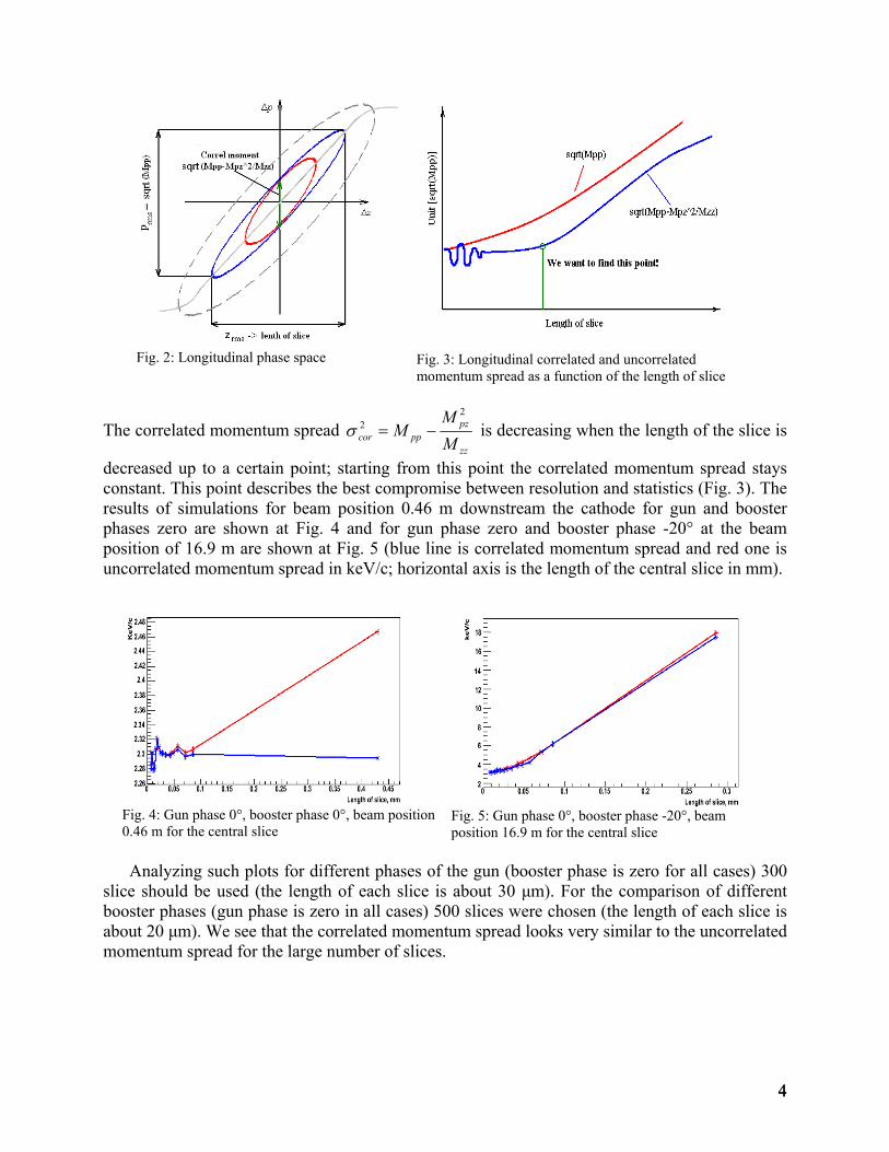
Fig. 2: Longitudinal phase space
Fig. 3: Longitudinal correlated and uncorrelated momentum spread as a function of the length of slice
The correlated momentum spread zz
pzppcor M
MM
22 −=σ is decreasing when the length of the slice is
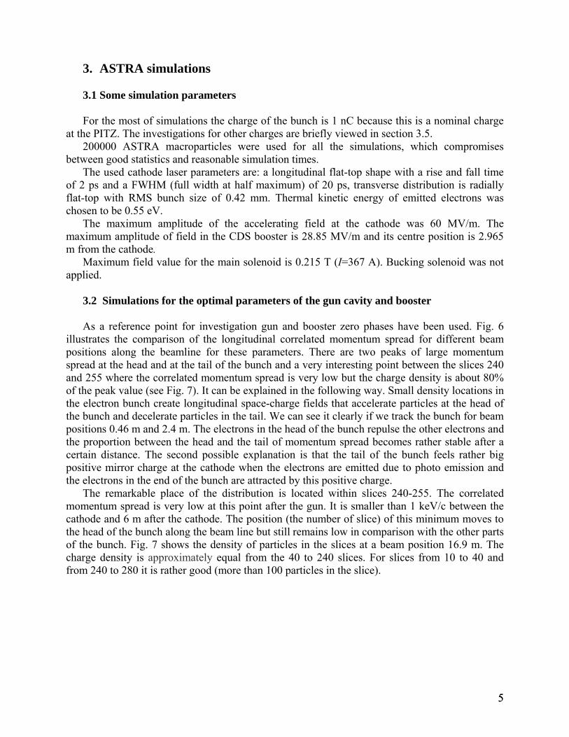
decreased up to a certain point; starting from this point the correlated momentum spread stays constant. This point describes the best compromise between resolution and statistics (Fig. 3). The results of simulations for beam position 0.46 m downstream the cathode for gun and booster phases zero are shown at Fig. 4 and for gun phase zero and booster phase -20° at the beam position of 16.9 m are shown at Fig. 5 (blue line is correlated momentum spread and red one is uncorrelated momentum spread in keV/c; horizontal axis is the length of the central slice in mm).
Fig. 5: Gun phase 0°, booster phase -20°, beam position 16.9 m for the central slice
Fig. 4: Gun phase 0°, booster phase 0°, beam position 0.46 m for the central slice Analyzing such plots for different phases of the gun (booster phase is zero for all cases) 300
slice should be used (the length of each slice is about 30 μm). For the comparison of different booster phases (gun phase is zero in all cases) 500 slices were chosen (the length of each slice is about 20 μm). We see that the correlated momentum spread looks very similar to the uncorrelated momentum spread for the large number of slices.
44
3. ASTRA simulations
3.1 Some simulation parameters
For the most of simulations the charge of the bunch is 1 nC because this is a nominal charge at the PITZ. The investigations for other charges are briefly viewed in section 3.5.
200000 ASTRA macroparticles were used for all the simulations, which compromises between good statistics and reasonable simulation times.
The used cathode laser parameters are: a longitudinal flat-top shape with a rise and fall time of 2 ps and a FWHM (full width at half maximum) of 20 ps, transverse distribution is radially flat-top with RMS bunch size of 0.42 mm. Thermal kinetic energy of emitted electrons was chosen to be 0.55 eV.
The maximum amplitude of the accelerating field at the cathode was 60 MV/m. The maximum amplitude of field in the CDS booster is 28.85 MV/m and its centre position is 2.965 m from the cathode.
Maximum field value for the main solenoid is 0.215 T (I=367 A). Bucking solenoid was not applied.
3.2 Simulations for the optimal parameters of the gun cavity and booster
As a reference point for investigation gun and booster zero phases have been used. Fig. 6
illustrates the comparison of the longitudinal correlated momentum spread for different beam positions along the beamline for these parameters. There are two peaks of large momentum spread at the head and at the tail of the bunch and a very interesting point between the slices 240 and 255 where the correlated momentum spread is very low but the charge density is about 80% of the peak value (see Fig. 7). It can be explained in the following way. Small density locations in the electron bunch create longitudinal space-charge fields that accelerate particles at the head of the bunch and decelerate particles in the tail. We can see it clearly if we track the bunch for beam positions 0.46 m and 2.4 m. The electrons in the head of the bunch repulse the other electrons and the proportion between the head and the tail of momentum spread becomes rather stable after a certain distance. The second possible explanation is that the tail of the bunch feels rather big positive mirror charge at the cathode when the electrons are emitted due to photo emission and the electrons in the end of the bunch are attracted by this positive charge.
The remarkable place of the distribution is located within slices 240-255. The correlated momentum spread is very low at this point after the gun. It is smaller than 1 keV/c between the cathode and 6 m after the cathode. The position (the number of slice) of this minimum moves to the head of the bunch along the beam line but still remains low in comparison with the other parts of the bunch. Fig. 7 shows the density of particles in the slices at a beam position 16.9 m. The charge density is approximately equal from the 40 to 240 slices. For slices from 10 to 40 and from 240 to 280 it is rather good (more than 100 particles in the slice).
55
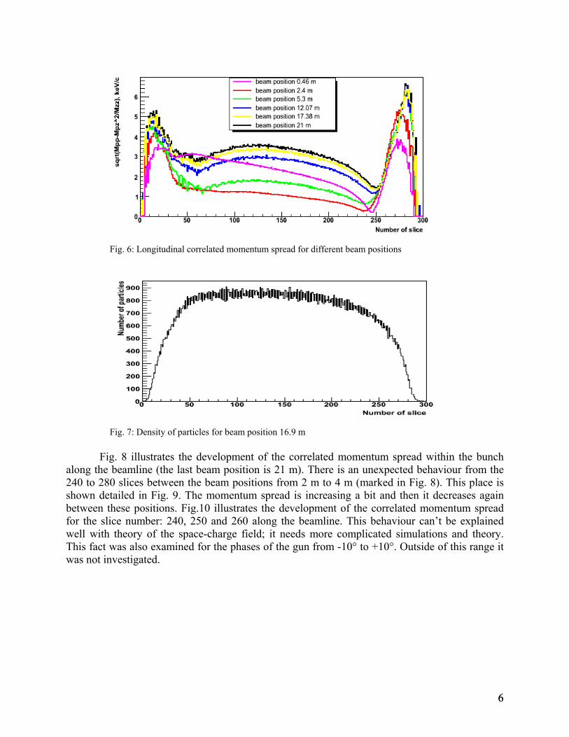
Fig. 6: Longitudinal correlated momentum spread for different beam positions
Fig. 7: Density of particles for beam position 16.9 m
Fig. 8 illustrates the development of the correlated momentum spread within the bunch
along the beamline (the last beam position is 21 m). There is an unexpected behaviour from the 240 to 280 slices between the beam positions from 2 m to 4 m (marked in Fig. 8). This place is shown detailed in Fig. 9. The momentum spread is increasing a bit and then it decreases again between these positions. Fig.10 illustrates the development of the correlated momentum spread for the slice number: 240, 250 and 260 along the beamline. This behaviour can’t be explained well with theory of the space-charge field; it needs more complicated simulations and theory. This fact was also examined for the phases of the gun from -10° to +10°. Outside of this range it was not investigated.
66
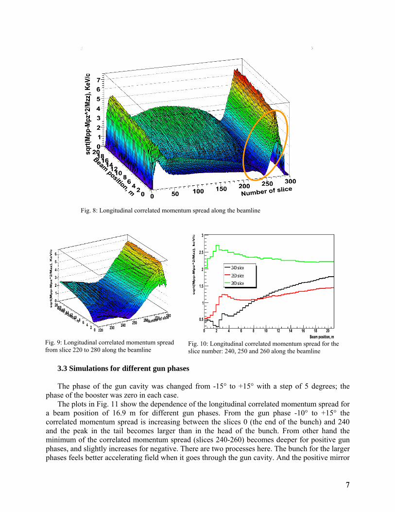
Fig. 8: Longitudinal correlated momentum spread along the beamline
Fig. 9: Longitudinal correlated momentum spread from slice 220 to 280 along the beamline
Fig. 10: Longitudinal correlated momentum spread for the slice number: 240, 250 and 260 along the beamline
3.3 Simulations for different gun phases
The phase of the gun cavity was changed from -15° to +15° with a step of 5 degrees; the
phase of the booster was zero in each case. The plots in Fig. 11 show the dependence of the longitudinal correlated momentum spread for
a beam position of 16.9 m for different gun phases. From the gun phase -10° to +15° the correlated momentum spread is increasing between the slices 0 (the end of the bunch) and 240 and the peak in the tail becomes larger than in the head of the bunch. From other hand the minimum of the correlated momentum spread (slices 240-260) becomes deeper for positive gun phases, and slightly increases for negative. There are two processes here. The bunch for the larger phases feels better accelerating field when it goes through the gun cavity. And the positive mirror
77
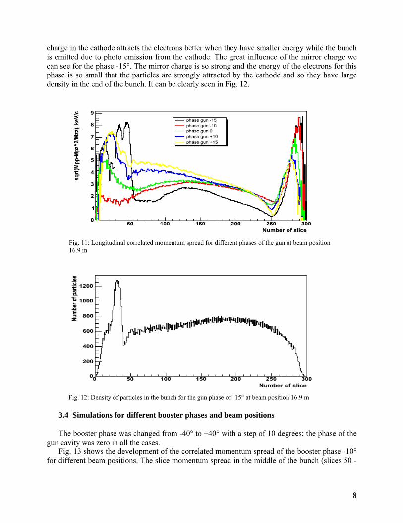
charge in the cathode attracts the electrons better when they have smaller energy while the bunch is emitted due to photo emission from the cathode. The great influence of the mirror charge we can see for the phase -15°. The mirror charge is so strong and the energy of the electrons for this phase is so small that the particles are strongly attracted by the cathode and so they have large density in the end of the bunch. It can be clearly seen in Fig. 12.
Fig. 11: Longitudinal correlated momentum spread for different phases of the gun at beam position 16.9 m
Fig. 12: Density of particles in the bunch for the gun phase of -15° at beam position 16.9 m 3.4 Simulations for different booster phases and beam positions
The booster phase was changed from -40° to +40° with a step of 10 degrees; the phase of the
gun cavity was zero in all the cases. Fig. 13 shows the development of the correlated momentum spread of the booster phase -10°
for different beam positions. The slice momentum spread in the middle of the bunch (slices 50 -
88
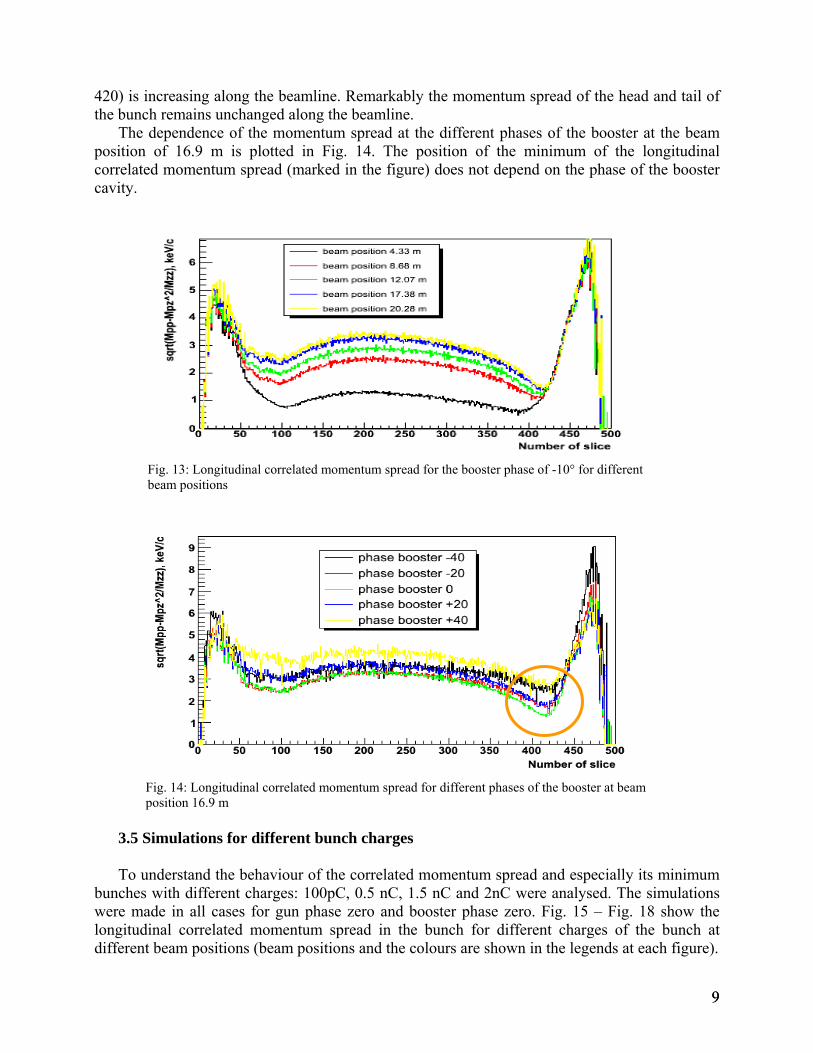
420) is increasing along the beamline. Remarkably the momentum spread of the head and tail of the bunch remains unchanged along the beamline.
The dependence of the momentum spread at the different phases of the booster at the beam position of 16.9 m is plotted in Fig. 14. The position of the minimum of the longitudinal correlated momentum spread (marked in the figure) does not depend on the phase of the booster cavity.
Fig. 13: Longitudinal correlated momentum spread for the booster phase of -10° for different beam positions
Fig. 14: Longitudinal correlated momentum spread for different phases of the booster at beam position 16.9 m
3.5 Simulations for different bunch charges
To understand the behaviour of the correlated momentum spread and especially its minimum
bunches with different charges: 100pC, 0.5 nC, 1.5 nC and 2nC were analysed. The simulations were made in all cases for gun phase zero and booster phase zero. Fig. 15 – Fig. 18 show the longitudinal correlated momentum spread in the bunch for different charges of the bunch at different beam positions (beam positions and the colours are shown in the legends at each figure).
99
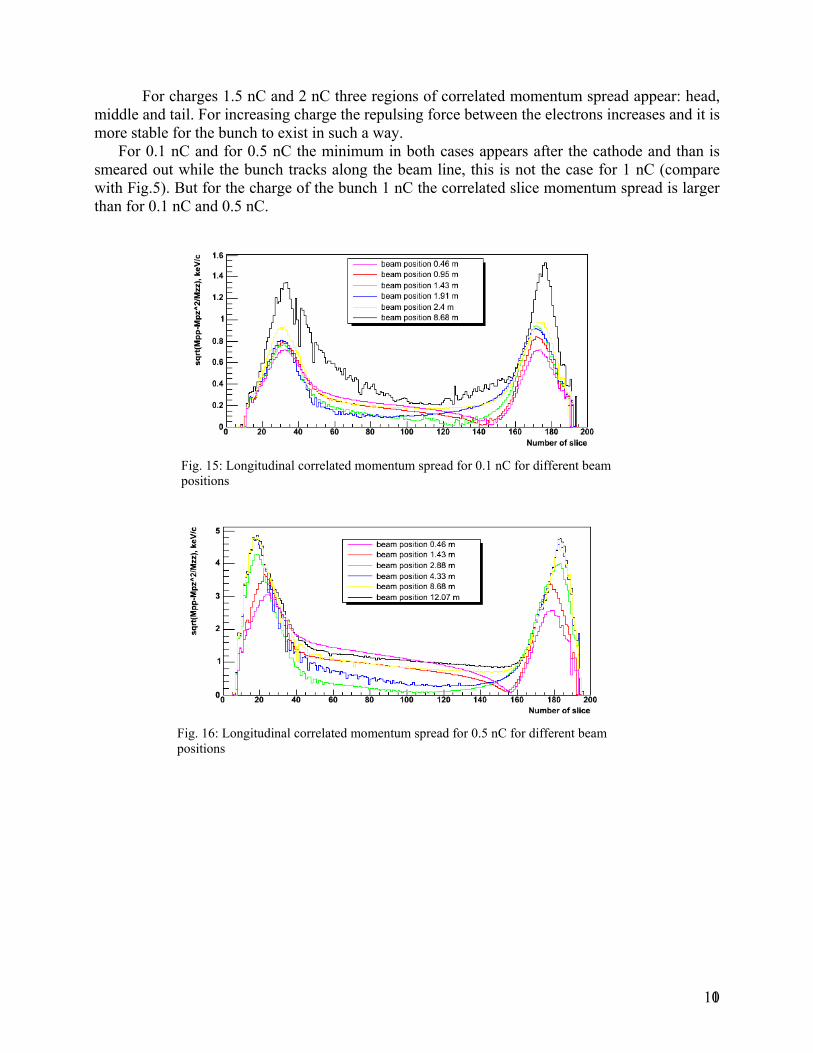
For charges 1.5 nC and 2 nC three regions of correlated momentum spread appear: head, middle and tail. For increasing charge the repulsing force between the electrons increases and it is more stable for the bunch to exist in such a way.
For 0.1 nC and for 0.5 nC the minimum in both cases appears after the cathode and than is smeared out while the bunch tracks along the beam line, this is not the case for 1 nC (compare with Fig.5). But for the charge of the bunch 1 nC the correlated slice momentum spread is larger than for 0.1 nC and 0.5 nC.
Fig. 15: Longitudinal correlated momentum spread for 0.1 nC for different beam positions
Fig. 16: Longitudinal correlated momentum spread for 0.5 nC for different beam positions
101
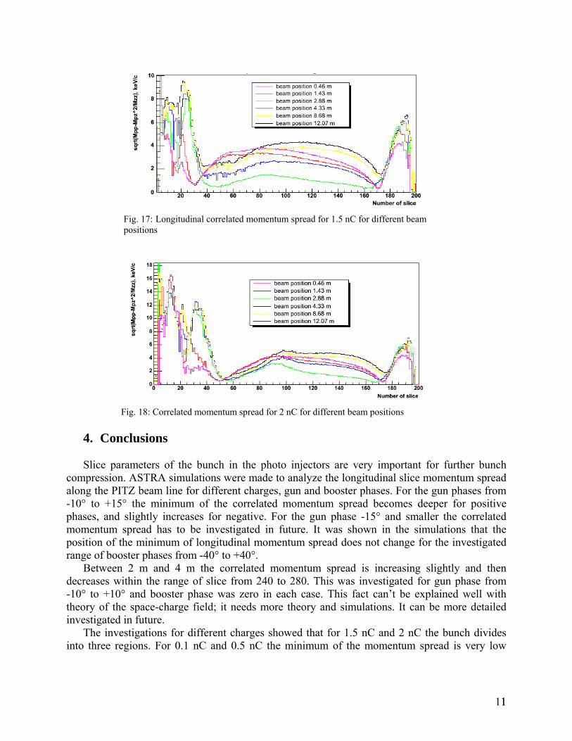
Fig. 17: Longitudinal correlated momentum spread for 1.5 nC for different beam positions
Fig. 18: Correlated momentum spread for 2 nC for different beam positions 4. Conclusions
Slice parameters of the bunch in the photo injectors are very important for further bunch
compression. ASTRA simulations were made to analyze the longitudinal slice momentum spread along the PITZ beam line for different charges, gun and booster phases. For the gun phases from -10° to +15° the minimum of the correlated momentum spread becomes deeper for positive phases, and slightly increases for negative. For the gun phase -15° and smaller the correlated momentum spread has to be investigated in future. It was shown in the simulations that the position of the minimum of longitudinal momentum spread does not change for the investigated range of booster phases from -40° to +40°.
Between 2 m and 4 m the correlated momentum spread is increasing slightly and then decreases within the range of slice from 240 to 280. This was investigated for gun phase from -10° to +10° and booster phase was zero in each case. This fact can’t be explained well with theory of the space-charge field; it needs more theory and simulations. It can be more detailed investigated in future.
The investigations for different charges showed that for 1.5 nC and 2 nC the bunch divides into three regions. For 0.1 nC and 0.5 nC the minimum of the momentum spread is very low
111
(reference to 1 nC). Further work should include the analysis the differences of the gain in
density modulation G≈ρind
ρi for the increasing charge.
5. Acknowledgements
First of all I’d like to thank my supervisor Juliane Roensch for help and being very kind and
careful on me. I want to thank Mikhail Krasilnikov for his very useful discussions and advices. Without him I wouldn’t be able to understand how many slices I need.
Also, I want to thank all members of PITZ group for creative and very friendly atmosphere and summer students for being good colleagues. I want to thank summer student Rudolf Hofler for explaining me a lot about ROOT programming.
I want to thank Dr. Hiller and Mrs. Baer for organizing the summer student program. Everything was well planned. I had a great experience and good time during the program. Thank you for very good trip to Hamburg.
6. References [1] Web-site of PITZ http://pitz.desy.de/[2] Floettmann K., ASTRA User Manual http://www.desy.de/~mpyflo/Astra_dokumentation/[3] Saldin E.L. et al, Longitudinal Space Charge Driven Microbunching Instability in TTF2 linac, TESLA-FEL-2003-02, 2003. [4] Huang Z. et al., Microbunching Instability due to Bunch Compression, SLAC-PUB-11597, 2005.
121


![Chapter 2 Response to Harmonic Excitation · 2018. 1. 30. · 2 2 2 2 22 2 ( ) cos( tan ) ( ) (2 ) n p nn n X f x t t T]Z Z Z Z Z ]Z Z ZZ §· ¨¸ ©¹ Add homogeneous and particular](https://static.fdocument.org/doc/165x107/61035af8ca0a8c1a4026d7b4/chapter-2-response-to-harmonic-excitation-2018-1-30-2-2-2-2-22-2-cos-tan.jpg)