
ARA Hot Water Drill Design and Performance€¦ · ARA Hot Water Drill Design and Performance ARA...
33
ARA Hot Water Drill Design and Performance ARA Review @ NSF Feb 20‐21, 2013 Terry Benson, UW‐PSL
Transcript of ARA Hot Water Drill Design and Performance€¦ · ARA Hot Water Drill Design and Performance ARA...

ARA Hot Water Drill Design and Performance
ARA Review @ NSFFeb 20‐21, 2013Terry Benson, UW‐PSL
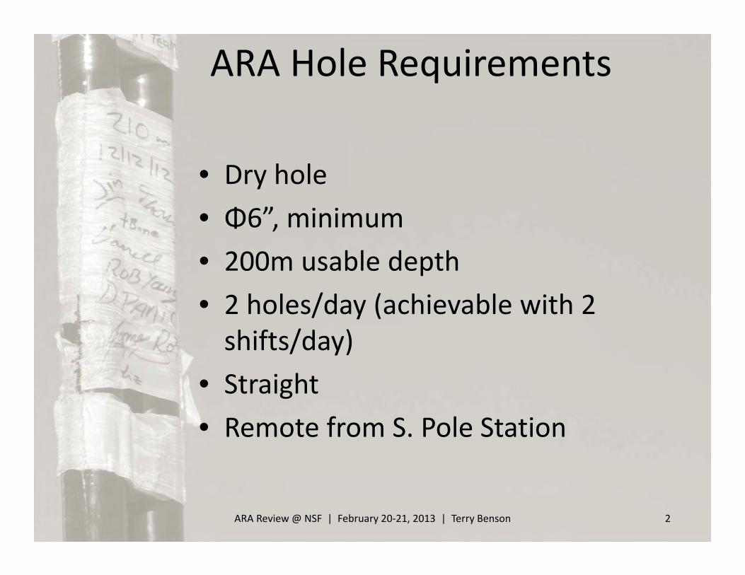
• Dry hole• Φ6”, minimum• 200m usable depth• 2 holes/day (achievable with 2 shifts/day)
• Straight• Remote from S. Pole Station
ARA Review @ NSF | February 20‐21, 2013 | Terry Benson 2
ARA Hole Requirements

ARA Review @ NSF | February 20‐21, 2013 | Terry Benson 3
ARAHWD History2010‐2011
– Initial build season– IceCube Enhanced Hot Water Trencher ‐> ARAHWD

ARA Review @ NSF | February 20‐21, 2013 | Terry Benson 4
ARAHWD History2010‐2011
– Initial build season– IceCube Enhanced Hot Water Trencher ‐> ARAHWD– 5 holes @ ARA Test Bed (40m dry)– 1 test hole (180m wet)– Drill under‐powered

ARAHWD History
ARA Review @ NSF | February 20‐21, 2013 | Terry Benson 5
2011‐2012– Modest upgrade season: +2 heaters, +recovery water pump, new melter– First attempt to 200m, first attempt at dry holes– 2 test holes @ ICL (190m wet, 70m dry)– 6 instrument holes @ ARA1 (2x 60m, 4x 100m)– Tough drilling season, equipment failures/loss, long shifts– Lessons learned
• Hole freeze‐back faster than predicted, drilling efficiencies lower than predicted• Equipment not reliable• System not capable of producing 200m dry holes in reasonable time• Clear that ARA37 drill concept needed to be realized

ARA Review @ NSF | February 20‐21, 2013 | Terry Benson 6
ARAHWD History2012‐2013
– SUCCESS!– Major upgrade season: new system architecture, drill/pump simultaneous, new
hose reel, new drillheads, +drill control center, new generators– 13 holes
• All φ6+” dia x 200m deep dry• 1x ICL test hole• 6x @ ARA2• 6x @ ARA3
– Lessons Learned• It works! But new territory for drilling method and hole type• New equipment, some kinks to iron out• Operations, new system = a few growing pains

11‐12 System vs. 12‐13 System
7
11‐12 System TARGET 12‐13 System ACTUAL 12‐13 System
Drilling Method Lost‐water drilling Water‐recovery
Pumping Method Drill, then pump Drill/pump simultaneous
Drill Water Deliver 10 GPM at 87°C 12 GPM at 88°C
% power down‐hole/snow‐melting 45% / 55% 100% / 0%
Net Water Production per 100 meters ‐2500 gal +600 gal
Drilling Rate 0.34 m/min 0.6 – 1.0 m/min
Max Target Depth in 10 hr1 120 m 200 m
Time2 to drill Φ6+”, dry hole…
to 40 meters (firn only) 1.9 hr 1 hr
to 100 meters (incl firn) 4.2 hr 2 hr
to 200 meters (incl firn) 17 hr 5 hr
1. Includes total hole‐to‐hole cycle (setup, drill/pump, pack‐up, move).2. Time spent drilling firn and ice only.
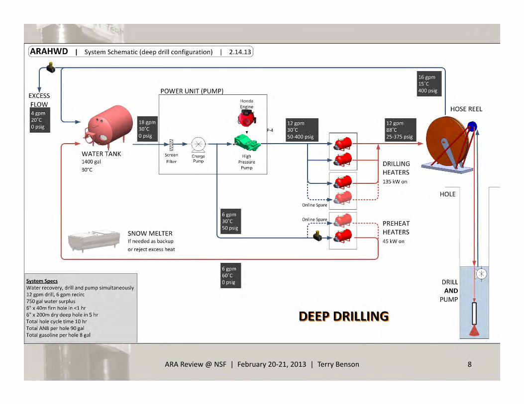
System Schematic
ARA Review @ NSF | February 20‐21, 2013 | Terry Benson 8

2012 Drill System UpgradesNew Drilling Method:PUMP/DRILL AT SAME TIME
Recirculated water column travels down with drillhead. Hot water sprays out nozzle and travels some distance back up the hole to the pump, where the water is pumped back to the surface. Hole diameter is developed between nozzle and pump.
• Closes loop and returns water during drilling
– No snow melting, net water production
– System capacity effectively doubled• Leaves dry hole above
– No freezeback!– 1 step = faster production rate
ARA Review @ NSF | February 20‐21, 2013 | Terry Benson 9
Pump
Pump Inlet
Hot SupplyCold Return
Diameter Qualifier
Extension Hose, 10m
Nozzle Stem
Traveling Water Column
↑DryHole

PUMP/DRILL AT SAME TIME
NEW DRILLHEADS – pump, head sensors, diameter
qualifier integrated together– nozzle stem 10m below– motor controller for auto run
NEW HOSE/CABLE BUNDLE – 2 hoses (supply/return, 1” ID, load‐
carrying)– combo cable (3‐phase pump power
and signal cable)
NEW HOSE REEL – single width spiral configuration– dual‐motor drum+sheave load
sharing– no level wind for simplicity and
improved safety– insulated
ARA Review @ NSF | February 20‐21, 2013 | Terry Benson 10
2012 Drill System Upgrades

NEW DRILL CONTROL CENTER (DCC)– centralized control and monitor– heated DNF space for motor
drives and controls– more reliable safeties and
controls
NEW GENERATORS– 2x (redundant) ASC‐supplied 50
kW generators– high reliability
INSTRUMENTATION AND ELECTRICAL – additional system
instrumentation– reworked electrical distribution
ARA Review @ NSF | February 20‐21, 2013 | Terry Benson 11
2012 Drill System Upgrades

IMPROVED PLUMBING AND HEATING– New charge pump– simplified plumbing, flexibility,
bigger lines– tested/tuned heaters
SHELTERING– Warm space and wind breaks for
crew and equipment– NGH
WIRELESS DAQ– Drill data recorded to laptop– PDAs
ARA Review @ NSF | February 20‐21, 2013 | Terry Benson 12
2012 Drill System Upgrades

Other things that made success possible
• Contributions of the Collaboration and partners– Delaware: James Roth electrical lead, full time on/off ice– Belgium: Thomas Meures 2nd season as driller, 2 weeks of help off‐ice in North– Kansas: Rob Young transitioned to full time driller mid‐season– ASC: Bert transitioned to full time driller mid‐season (good model for future
seasons)
• Experienced and well‐rounded crew• Fantastic support from ASC
– Cargo– Real‐time support requests (Hose reel in heavy shop, meals)
• Great weather!• Thorough test phase in the North prior to shipment• Thorough system shakedown at ICL prior to moving into field• Well prepared/maintained documentation, procedures, and logging
ARA Review @ NSF | February 20‐21, 2013 | Terry Benson 13

ARAHWD2012
Flow X TempTemp [C]
50 60 70 80 85 90 Slug Delay [min]
Flow
[gpm
]
6 300 360 420 480 510 540 5.0
8 400 480 560 640 680 720 3.8
10 500 600 700 800 850 900 3.0
12 600 720 840 960 1020 1080 2.5
14 700 840 980 1120 1190 1260 2.1
16 800 960 1120 1280 1360 1440 1.9
DRILL SPEED: 7.5” hole
Drill Speed [m/min], 7.5" HoleReturn Water Temp [C]
5 10 15 20
Flow
X Tem
p [gpm
x C]
300 0.21 0.19 0.17 0.16400 0.28 0.25 0.23 0.21500 0.35 0.32 0.29 0.26600 0.42 0.38 0.35 0.31700 0.49 0.45 0.40 0.37800 0.56 0.51 0.46 0.42900 0.63 0.57 0.52 0.471000 0.70 0.64 0.58 0.521100 0.77 0.70 0.64 0.581200 0.84 0.76 0.69 0.631300 0.91 0.83 0.75 0.68
(Example of drill tools available to crew)

ARA Review @ NSF | February 20‐21, 2013 | Terry Benson 15
(Example of drill tools available to crew)

ARA Review @ NSF | February 20‐21, 2013 | Terry Benson 16
This shows there were no serious system issues that prevented us from
following our prescribed drill
strategy. Most holes looked like this.

ARA Review @ NSF | February 20‐21, 2013 | Terry Benson 17
6 holes in 9 working days 6 holes in 7 working days

ARA Review @ NSF | February 20‐21, 2013 | Terry Benson 18

ARA Review @ NSF | February 20‐21, 2013 | Terry Benson 19
12‐13 Hole Summary Chart
Firn DrillDeep Drill Total
1 Test Hole ICL 1.4 7.0 8.4 Backtrack @ 140m to tune torque parameters 91 7 ‐2 A2D1 ARA2 1.5 5.2 6.9 ‐ 74 5 1313 A2D2 ARA2 1.1 6.7 7.9 ‐ 85 8 7954 A2D5 ARA2 NA 7.4 NA ‐ 86 9 ‐5 A2D4 ARA2 1.3 5.4 6.9 good hole, good data, switch to other drillhead 74 5 8366 A2D3 ARA2 1.3 7.7 9.0 Difficult getting past narrow spot @ 27m 98 8 51
7 A2D6 ARA2 1.1 11.8 12.912/18 Firn + Partial, 12/20 Deep but water fill in (136m) and head sensor fail, final depth delivered 12/23
139 10 956
8 A3D4 ARA3 1.5 5.8 7.3 Good hole 79 4 1468 (?)9 A3D1 ARA3 1.4 7.2 8.7 Difficult getting nozzle stem through firn hole 93 7 82910 A3D3 ARA3 3.1 6.4 9.4 ‐ 102 7 ‐11 A3D2 ARA3 2.2 4.8 7.0 ‐ 76 6 58812 A3D5 ARA3 1.8 5.7 7.4 ‐ 80 6 105813 A3D6 ARA3 2.1 5.6 7.8 ‐ 84 6 ‐
BEST 1.1 4.8 6.9 74 4 1058WORST 3.1 11.8 12.9 139 10 51AVERAGE 1.6 6.7 8.3 89 7 746
Gasoline [gal]
Net Water
Recovery [gal]
A: Fuel estimates based on (duration)x(fuel rate) Gen rate = 2.05 gph Heater rate = 8.75 gph
Durations [hr]
Hole Sequence Hole Location Issues/Comments
Fuel AN8 [gal] A

11‐12 System vs. 12‐13 System
20
11‐12 System TARGET 12‐13 System ACTUAL 12‐13 System
Drilling Method Lost‐water drilling Water‐recovery Water‐recovery
Pumping Method Drill, then pump Drill/pump simultaneous Drill/pump simultaneous
Drill Water Deliver 10 GPM at 87°C 12 GPM at 88°C 12 GPM at 81°C
% power down‐hole/snow‐melting 45% / 55% 100% / 0% 100% / 0%
Net Water Production per 100 meters ‐2500 gal +600 gal +355 gal average+504 gal best?
Drilling Rate 0.34 m/min 0.6 – 1.0 m/min 0.63 m/min average0.68 m/min best
Max Target Depth in 10 hr1 120 m 200 m 200 m
Time2 to drill Φ6+”, dry hole…
to 40 meters (firn only) 1.9 hr 1 hr 1.6 hr average1.1 hr best
to 100 meters (incl firn) 4.2 hr 2 hr 4.0 hr average est.2.8 hr best est.
to 200 meters (incl firn) 17 hr 5 hr 8.3 hr average5.9 hr best of the best
1. Includes total hole‐to‐hole cycle (setup, drill/pump, pack‐up, move).2. Time spent drilling firn and ice only.

• No injuries• A few bouts of sickness, morale overall high• 5 core drillers + 1‐2 helpers
– 4‐5 drillers needed at start/end of hole– 2‐3 drillers needed during drilling
• Arrival/Departure checklists were utilized, manual drill logs in addition to DAQ, pre‐op meetings
• Most shifts during production drilling extended to 12 hrs– Unsustainable for extended seasons– However, some steps (pickling, warm‐up, maintenance)
eliminated with two‐shift operation, and operations expected to become more efficient (new system)
– We believe this system can produce 2 holes per day with shift limited to 10 hours or less
ARA Review @ NSF | February 20‐21, 2013 | Terry Benson 21
Operations
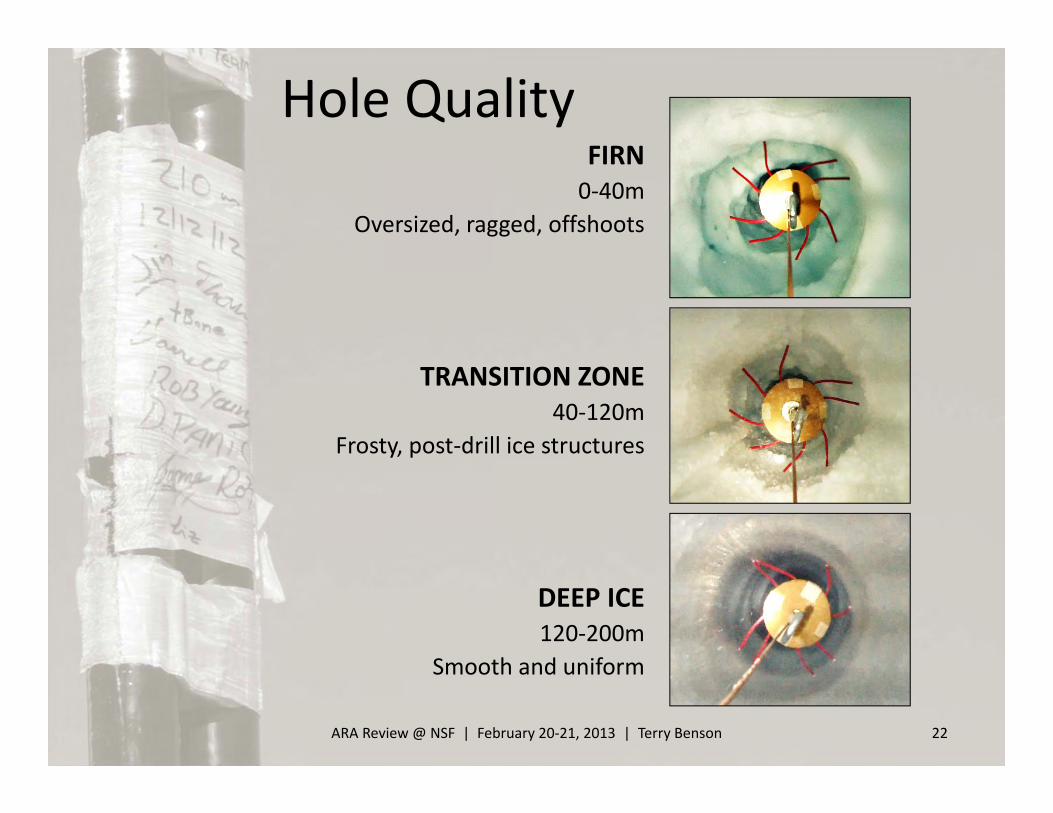
FIRN0‐40m
Oversized, ragged, offshoots
TRANSITION ZONE40‐120m
Frosty, post‐drill ice structures
DEEP ICE120‐200m
Smooth and uniform
ARA Review @ NSF | February 20‐21, 2013 | Terry Benson 22
Hole Quality

ARA Review @ NSF | February 20‐21, 2013 | Terry Benson 23
Questions?

Additional Slides…
ARA Review @ NSF | February 20‐21, 2013 | Terry Benson 24

25
ARA DrillheadOverview
ARA DrillheadOverview
FIRNDrilling
DEEPDrilling
Full Cone Spray
Firn Nozzle Attachment
Jet Spray
Nozzle Stem (weight)
Extension HoseL = 10m
Hot Supply water exits here, attach firn nozzle or extension hose
Compliant hole diameter qualifier provides indication of narrow spots and maximizes return water velocity
Cold Return water enters pump shroud hereDuring backflush, water exits here and pours over qualifier
Polycarbonate shroud directs return water over motor surface to provide cooling
Pump
Motor
Pump Inlet
4x insulated SS tubes carry the hot water around the pump
4x sets of tie rods support load below the pump
Top section houses manifolding, pressure transducers, and recirculation valving
Hot circulation ring around top edge of drillhead for emergency up‐reaming

ARA Hose Reel OverviewARA Hose Reel OverviewHose and cable bundle• 2x hoses and 1x combo cable• Multi‐reel joined at hole not a solution
– Load to be shared amongst all 3 members, intricate syncing control would be required
– Extra task at hole of joining/separating members
• Manufactured umbilical with round cross‐section too expensive, too big• Decided to build custom from separate pieces, resulting in a ribbon profileSingle width spiral configuration• Accommodates hose bundle design with ribbon cross‐section• Improves safety and reduces complexity by eliminating level wind and
associated fleet distance• 2x familiar applications that have succusfully utilized this design
– Rapid Air Movement (RAM) Drill– Independent Firn Drill
• Large diameter required to accommodate full length of hose, so design incorporates a 45° pivot to allow the reel to fit on an LC‐130 aircraft
Dual‐drive, load sharing system• A dry hole results in high down‐hole loads (no bouyancy)• High loads + many layers would collapse the lower layers of hose if using only
the drum to react the load• Motorized sheave utilizes friction with the bundle to react a majority (~80%) of
the down‐hole load, like a capstan winch• In this mode, the sheave operates in velocity mode and is master to the drum,
therefore payout and speed is directly controlled without effects of changing diameter
• The drum operates in torque mode and is slave to the sheave, and the hose is wrapped onto the drum at only 20% down‐hole load
Structural Insulated Panels (SIPs) used for flanges
Electrical slip ring(480v 3ph, comms)
Other Side:2‐port rotary hydraulic unionFailsafe disc brackHeated valving box
Drum operates in torquemode during deep drilling,
is slave to sheave
Motorized sheave operates in speedmode during deep drilling, is master to drum Mounting face
for beam and trolley hoist
Redundant load cells
Payout/speed encoder
Skis allow for light towing on snowSHIPPosition
INSTALLEDPosition
ARA Review @ NSF | February 20‐21, 2013 | Terry Benson 27

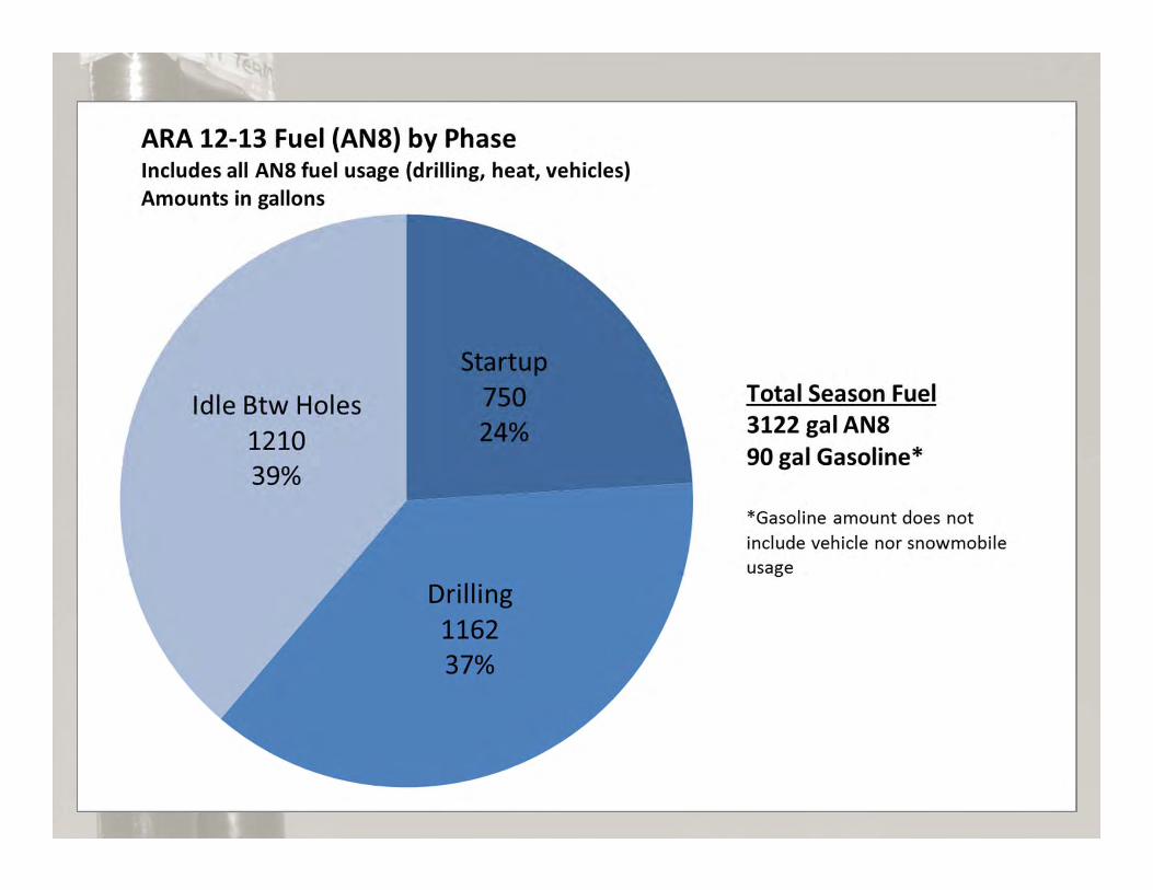
Water Usage/Production
ARA Review @ NSF | February 20‐21, 2013 | Terry Benson 28

Why Hot Water?• Leverage experience and equipment available towards end of
IceCube drilling• Fast• Other technologies considered
– Rapid Air Movement (RAM) drill• Air compressors supply a high speed air motor at end of drill hose, spinning a
cutting bit. Chips are carried out of hole by return air flow.• Very fast, φ4” dia x 90m in 20 min in some field locations• Would require basically new drill to accommodate φ6” dia x 200m holes• Firn at South Pole very deep = too much return air escapes = chips not carried out
of hole• Existing drill tested at South Pole during 10‐11 season, average depth achieved
was about 40m– Reverse Circulating Drill Rig
• Discussed with manufacturers, an existing suitable rig was identified, but would require some rework for our application
• Initial field testing of this technology too expensive and risky, would need to invest $700K+ for first field season, with too many unknowns
• Needed to choose primary path (hot water) and focus on that, so this concept is young, but minimal efforts have been continued in parallel
ARA Review @ NSF | February 20‐21, 2013 | Terry Benson 29

Modeling• Performance models
– EES model revised since 11‐12 to reflect new system architecture and better‐understood system efficiencies
– Excel model done independently and in parallel– The two models were used to validate each other
• Hole refreeze– IceCube thermal model tailored for ARA to predict
refreeze rate and help strategize water‐filled holes (done in early 11‐12 season)
• Nozzle distance– IceCube thermal model used to help determine target
distance between nozzle and pump. This is new territory for the thermal model. ARA 12‐13 drill data will be used to validate and hone some of the principle assumptions made in the thermal model in the nozzle region.
ARA Review @ NSF | February 20‐21, 2013 | Terry Benson 30

ARA2 Map
ARA Review @ NSF | February 20‐21, 2013 | Terry Benson 31

ARA3 Map
ARA Review @ NSF | February 20‐21, 2013 | Terry Benson 32

ARA37 Map
ARA Review @ NSF | February 20‐21, 2013 | Terry Benson 33