ANALYSIS OF THE SWITCHED RELUCTANCE MOTOR (SRM) … · l 1 = arcAB= jABj ˇ 2 (6) The lengths in...
6
Journal of ELECTRICAL ENGINEERING, VOL. 55, NO. 7-8, 2004, 195–200 ANALYSIS OF THE SWITCHED RELUCTANCE MOTOR (SRM) PARAMETERS Pavol Rafajdus * — Ivan Zrak ** — Val´ eria Hrabovcov´ a * In the paper the model for analysis of the Switched Reluctance Motor (SRM) parameters is described. The inductances L , linkage flux Ψ, and torque T are calculated on the basis of geometrical dimensions and B – H curves of the material. As the outputs the waveforms of the L , Ψ and T vs current and rotor position are gained. Keywords: switched reluctance motor, analytical model, aligned and unaligned inductance, flux linkage, torque production, rotor position. 1 INTRODUCTION To be able to investigate the SRM performances, in- cluding the design of the control circuits, it is necessary to know its parameters, such as inductance, flux linkage and torque. There are more possibilities how to do it, eg by measurements or calculation on the basis of electromag- netic field analysis. For this purpose it is possible to use the Finite Element Method (FEM) or to develop an ana- lytical model. This paper is focused on the development of such an analytical model allowing calculation of SRM parameters on the basis of geometrical dimensions of its cross-section area and B – H curve of the used iron mate- rial. This analytical model employs a numerical iteration to find the magnetic reluctance along the magnetic flux path and hence the inductance changing its value from aligned to unaligned rotor position for various values of excitation current. The inductance is then used to calcu- late the flux linkage and hence the torque given by the co-energy varying during the rotor movement. 2 ANALYTICAL MODEL The model is developed for the 3-phase, 12/8 SRM, shown in Fig. 1. Its rating is as follows: 3.7 kW, 11.8 Nm, 3000 rpm, 540 V. The motor has a 4-pole magnetic field, which means that the angle between aligned and unaligned positions is 22.5 ◦ . The rotor position θ =0 ◦ , when the axis of the excited stator pole is identical with the axis of rotor pole, is defined as aligned [1]. The position θ = 22.5 ◦ , when the axis between two rotor poles is identical with the axis of the excited stator pole, is defined as unaligned position [1]. In the sequel, a detailed procedure for calculating the inductance and other parameters will be described. D D 0 D sh h r h s b sy d b ry b r b s Fig. 1. 12/8 SRM cross-section. 2.1 Calculation procedure The well-known expression for inductance calculation will be used: L = (2N c ) 2 R (1) where N c is the number of the turns of the excited coil, 2N c means that inside the closed magnetic path there are two times N c . R is the reluctance of the magnetic circuit in which the inductance is calculated. Since it is a complicated magnetic circuit, consisting of some parts, such as stator pole denoted with subscript sp , stator yoke ( sy ), air gap ( δ ), rotor pole ( rp ), rotor yoke ( ry ), the to- tal reluctance will be the sum of single reluctances along the magnetic path. The reluctances will be calculated by means of geometrical dimensions and magnetic perme- ability: R = l Sμ = Hl BS (2) * University of ˇ Zilina, Faculty of Electrical Engineering, Vel’k´ y diel, 010 26 ˇ Zilina, Slovakia, e-mail: [email protected], [email protected] ** Elteco a.s., Rosinsk´ a cesta 15, 010 01 ˇ Zilina, Slovakia, e-mail: [email protected] ISSN 1335-3632 c 2004 FEI STU
Transcript of ANALYSIS OF THE SWITCHED RELUCTANCE MOTOR (SRM) … · l 1 = arcAB= jABj ˇ 2 (6) The lengths in...
Journal of ELECTRICAL ENGINEERING, VOL. 55, NO. 7-8, 2004, 195–200
ANALYSIS OF THE SWITCHEDRELUCTANCE MOTOR (SRM) PARAMETERS
Pavol Rafajdus∗— Ivan Zrak
∗∗— Valeria Hrabovcova
∗
In the paper the model for analysis of the Switched Reluctance Motor (SRM) parameters is described. The inductancesL , linkage flux Ψ, and torque T are calculated on the basis of geometrical dimensions and B –H curves of the material. As
the outputs the waveforms of the L , Ψ and T vs current and rotor position are gained.
K e y w o r d s: switched reluctance motor, analytical model, aligned and unaligned inductance, flux linkage, torque
production, rotor position.
1 INTRODUCTION
To be able to investigate the SRM performances, in-
cluding the design of the control circuits, it is necessary to
know its parameters, such as inductance, flux linkage and
torque. There are more possibilities how to do it, eg by
measurements or calculation on the basis of electromag-
netic field analysis. For this purpose it is possible to use
the Finite Element Method (FEM) or to develop an ana-
lytical model. This paper is focused on the development
of such an analytical model allowing calculation of SRM
parameters on the basis of geometrical dimensions of its
cross-section area and B –H curve of the used iron mate-
rial. This analytical model employs a numerical iteration
to find the magnetic reluctance along the magnetic flux
path and hence the inductance changing its value from
aligned to unaligned rotor position for various values of
excitation current. The inductance is then used to calcu-
late the flux linkage and hence the torque given by the
co-energy varying during the rotor movement.
2 ANALYTICAL MODEL
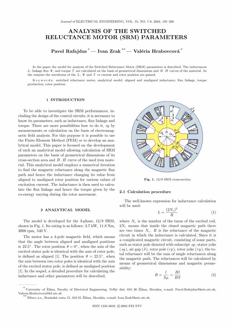
The model is developed for the 3-phase, 12/8 SRM,
shown in Fig. 1. Its rating is as follows: 3.7 kW, 11.8 Nm,
3000 rpm, 540 V.
The motor has a 4-pole magnetic field, which means
that the angle between aligned and unaligned positions
is 22.5◦ . The rotor position θ = 0◦ , when the axis of the
excited stator pole is identical with the axis of rotor pole,
is defined as aligned [1]. The position θ = 22.5◦ , when
the axis between two rotor poles is identical with the axis
of the excited stator pole, is defined as unaligned position
[1]. In the sequel, a detailed procedure for calculating the
inductance and other parameters will be described.
DD0 Dsh
hr
hs b sy
d
b ry
b r
bs
Fig. 1. 12/8 SRM cross-section.
2.1 Calculation procedure
The well-known expression for inductance calculationwill be used:
L =(2Nc)
2
R(1)
where Nc is the number of the turns of the excited coil,2Nc means that inside the closed magnetic path thereare two times Nc . R is the reluctance of the magneticcircuit in which the inductance is calculated. Since it isa complicated magnetic circuit, consisting of some parts,such as stator pole denoted with subscript sp , stator yoke(sy ), air gap (δ ), rotor pole (rp), rotor yoke (ry ), the to-tal reluctance will be the sum of single reluctances alongthe magnetic path. The reluctances will be calculated bymeans of geometrical dimensions and magnetic perme-ability:
R =l
Sµ=Hl
BS(2)
∗University of Zilina, Faculty of Electrical Engineering, Vel’ky diel, 010 26 Zilina, Slovakia, e-mail: [email protected],
Elteco a.s., Rosinska cesta 15, 010 01 Zilina, Slovakia, e-mail: [email protected]
ISSN 1335-3632 c© 2004 FEI STU
196 P. Rafajdus — I. Zrak — V. Hrabovcova: ANALYSIS OF THE SWITCHED RELUCTANCE MOTOR (SRM) PARAMETERS
Fig. 2. Plotting of magnetic flux distribution in the 12/8 SRMcross-section.
12
3
4
4
Fig. 3. Typical magnetic flux lines.
A
B'B
lsy1/2
lry1/2
w
q1
Dq
lsp1
ld1
lrp1
Fig. 4. Typical fux line No. 1 for two rotor positions shifted byangle ∆θ .
where l is the length of the magnetic path, S is thearea which is penetrated by the magnetic flux, magneticpermeability µ is given by the values of B and H in theB –H curve of the used material.
As the magnetic flux and, hence, the magnetic fluxdensity B are given by the reluctance R , in a ferromag-netic material both R and B are unknown. This problem
will be solved by means of magnetomotive force balance,given by Ampere’s Circuit Law [2], which can be writtenfor the SRM magnetic circuit in the form:
F = 2Nci =
∮
~Hd~l =∑
k
Hklk (3)
where k is gradually sp , sy , rp , ry , δ with their lengthl of the magnetic path and corresponding H (see alsoFig. 6). If on the left side a product of the exciting currentand of the number of turns equals to the product ofmagnetic field intensity H and the length of magneticpath l on the right side, then their difference is zero:
2Nci−∑
k
Hklk = 0 .
If this is not true, there will be a discrepancy, or betterto say an error
∆F = 2Nci−∑
k
Hklk . (4)
The purpose is to look for such values of i and H , to min-imize the ∆F , in ideal case to zero. It can be graduallymade by means of numerical iteration with a prescribedvalue of error ∆F . If the prescribed accuracy is achieved,then for a given exciting current i the magnetic field in-tensity H on the investigated length l of magnetic circuitis known.
Then on the basis of the B –H curve of the usedferromagnetic material the magnetic flux density B isdetermined and inserted into (2) to calculate reluctanceR and then inductance according (1). In the next thecalculation will be shown in detail.
2.2 Length of magnetic flux line and flux areacalculation
To explain in greater details the calculation procedurean example will be given in this chapter. In Fig. 2 the plotof the magnetic flux distribution in the SRM cross-sectionarea, gained by FEM, is shown.
For simplicity, all magnetic flux lines are divided in atleast four typical groups, in which their form and lengthare very similar (Fig. 3). For each group one typical fluxline is chosen. Its length will be calculated with the chang-ing of the rotor position. Each typical flux line is dividedonto intervals, corresponding to individual SRM parts(sp , sy , rp , ry , δ ). The length of individual intervalsis given as a sum of lines and arches creating the form ofthe flux line. The total length of one typical flux line isgiven by the sum of the lengths along all parts of the ma-chine. The calculation starts at θ = 22.5◦ , correspondingto the unaligned rotor position, and continues in the di-rection of rotor movement ω to the θ = 0◦ correspondingto the aligned rotor position. As an example some expres-sions derived for rotor position θ1 of the typical flux line
Journal of ELECTRICAL ENGINEERING VOL. 55, NO. 7-8, 2004 197
B'(x2', y2')
B(x2, y2)
|AB|
|AB'|
A(x1, y1)
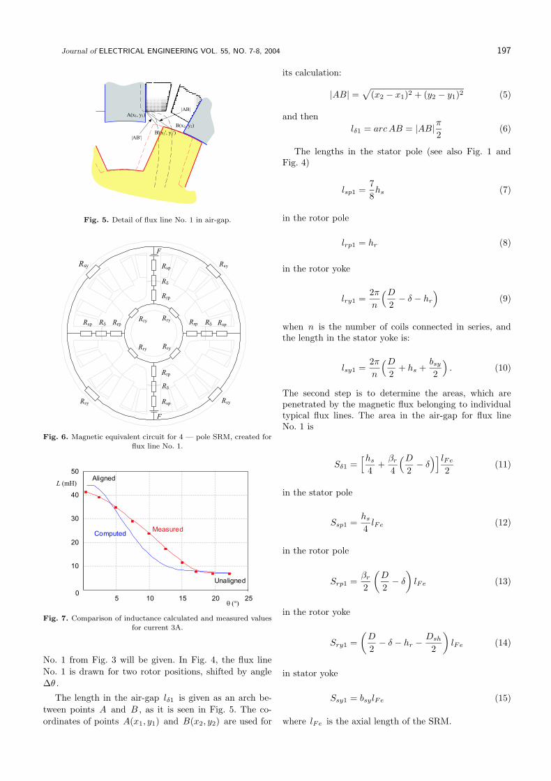
Fig. 5. Detail of flux line No. 1 in air-gap.
RsyRsp
Rd
Rrp
RryRry
RryRry
F
Rsy
Rsp
F
Rd
Rrp
RsyRsy
Rrp Rd RspRrpRdRsp
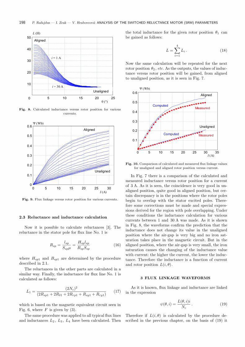
Fig. 6. Magnetic equivalent circuit for 4 — pole SRM, created forflux line No. 1.
10
20
30
40
50
05 10 15 20 25
q (°)
L (mH)
ComputedMeasured
Aligned
Unaligned
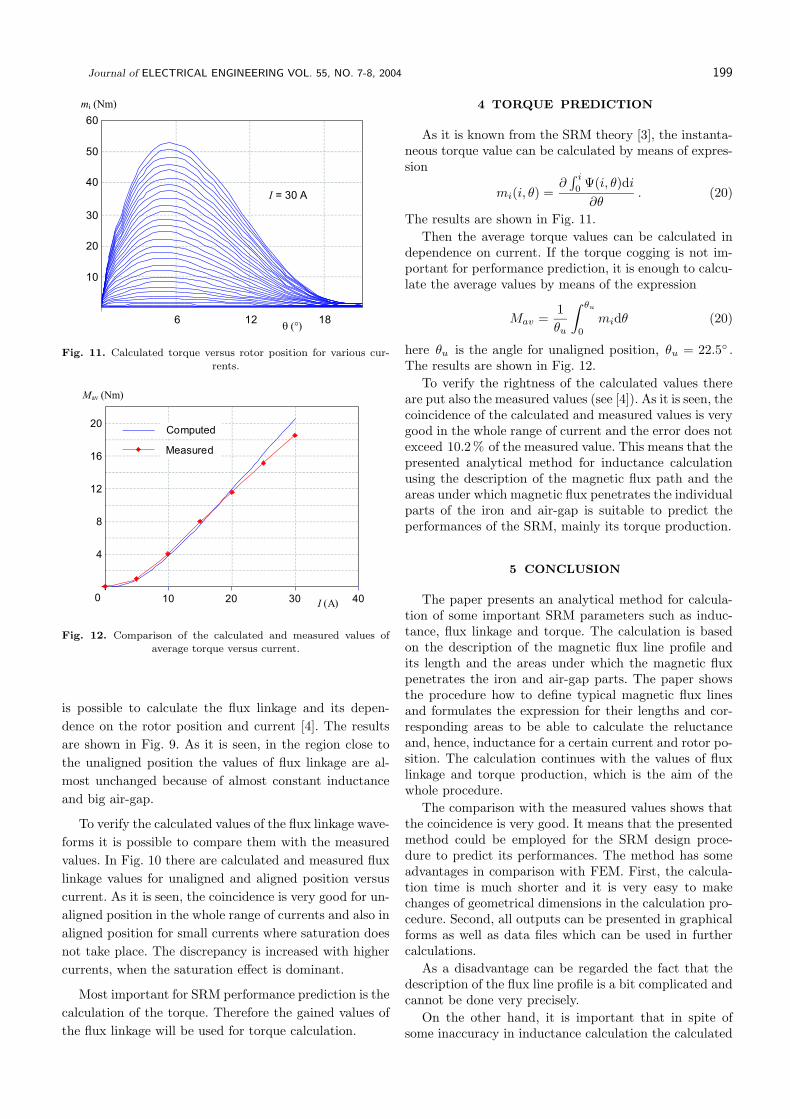
Fig. 7. Comparison of inductance calculated and measured valuesfor current 3A.
No. 1 from Fig. 3 will be given. In Fig. 4, the flux line
No. 1 is drawn for two rotor positions, shifted by angle
∆θ .
The length in the air-gap lδ1 is given as an arch be-
tween points A and B , as it is seen in Fig. 5. The co-
ordinates of points A(x1, y1) and B(x2, y2) are used for
its calculation:
|AB| =√
(x2 − x1)2 + (y2 − y1)2 (5)
and then
lδ1 = arcAB = |AB|π
2(6)
The lengths in the stator pole (see also Fig. 1 andFig. 4)
lsp1 =7
8hs (7)
in the rotor pole
lrp1 = hr (8)
in the rotor yoke
lry1 =2π
n
(D
2− δ − hr
)
(9)
when n is the number of coils connected in series, andthe length in the stator yoke is:
lsy1 =2π
n
(D
2+ hs +
bsy
2
)
. (10)
The second step is to determine the areas, which arepenetrated by the magnetic flux belonging to individualtypical flux lines. The area in the air-gap for flux lineNo. 1 is
Sδ1 =[hs
4+βr
4
(D
2− δ
)] lFe
2(11)
in the stator pole
Ssp1 =hs
4lFe (12)
in the rotor pole
Srp1 =βr
2
(
D
2− δ
)
lFe (13)
in the rotor yoke
Sry1 =
(
D
2− δ − hr −
Dsh
2
)
lFe (14)
in stator yoke
Ssy1 = bsylFe (15)
where lFe is the axial length of the SRM.
198 P. Rafajdus — I. Zrak — V. Hrabovcova: ANALYSIS OF THE SWITCHED RELUCTANCE MOTOR (SRM) PARAMETERS
0
10
20
30
40
50
5 10 15 20 25q (°)
L (H)
i = 1 A
i = 30 A
Aligned
Unaligned
Fig. 8. Calculated inductance versus rotor position for various
currents.
0
0.1
0.2
0.3
0.4
0.5
0.6
0 5 10 15 20 25 30I (A)
Y (Wb)
Aligned
Unaligned
Fig. 9. Flux linkage versus rotor position for various currents.
2.3 Reluctance and inductance calculation
Now it is possible to calculate reluctances [3]. Thereluctance in the stator pole for flux line No. 1 is
Rsp =lsp
Sspµ=Hsplsp
BspSsp
(16)
where Hsp1 and Bsp1 are determined by the proceduredescribed in 2.1.
The reluctances in the other parts are calculated in asimilar way. Finally, the inductance for flux line No. 1 iscalculated as follows:
L1 =(2Nc)
2
(2Rsp1 + 2Rδ1 + 2Rrp1 +Rsy1 +Rry1)(17)
which is based on the magnetic equivalent circuit seen inFig. 6, where F is given by (3).
The same procedure was applied to all typical flux linesand inductances L2 , L3 , L4 have been calculated. Then
the total inductance for the given rotor position θ1 canbe gained as follows:
L =
4∑
i=1
Li . (18)
Now the same calculation will be repeated for the nextrotor position θ2 , etc. As the outputs, the values of induc-tance versus rotor position will be gained, from alignedto unaligned position, as it is seen in Fig. 7.
Y (Wb)
0.1
0.2
0.3
0.4
0.5
0.6
0 5 10 15 20 25 30 35I (A)
Computed
Aligned
Measured
Unaligned
Computed Measured
Fig. 10. Comparison of calculated and measured flux linkage values
for unaligned and aligned rotor position versus current.
In Fig. 7 there is a comparison of the calculated andmeasured inductance versus rotor position for a currentof 3 A. As it is seen, the coincidence is very good in un-aligned position, quite good in aligned position, but cer-tain discrepancy is in the positions where the rotor polesbegin to overlap with the stator excited poles. There-fore some corrections must be made and special expres-sions derived for the region with pole overlapping. Underthese conditions the inductance calculation for variouscurrents between 1 and 30 A was made. As it is shownin Fig. 8, the waveforms confirm the prediction that theinductance does not change its value in the unalignedposition where the air-gap is very big and no iron sat-uration takes place in the magnetic circuit. But in thealigned position, where the air-gap is very small, the ironsaturation causes the changing of the inductance valuewith current: the higher the current, the lower the induc-tance. Therefore the inductance is a function of currentand rotor position L(i, θ) .
3 FLUX LINKAGE WAVEFORMS
As it is known, flux linkage and inductance are linkedin the expression
ψ(θ, i) =L(θ, i)i
Nc
. (19)
Therefore if L(i, θ) is calculated by the procedure de-scribed in the previous chapter, on the basis of (19) it
Journal of ELECTRICAL ENGINEERING VOL. 55, NO. 7-8, 2004 199
q (°)
10
20
30
40
50
60
0 6 12 18
mi (Nm)
I = 30 A
Fig. 11. Calculated torque versus rotor position for various cur-
rents.
4
8
12
16
20
0 10 20 30 40I (A)
Computed
Measured
Mav (Nm)
Fig. 12. Comparison of the calculated and measured values of
average torque versus current.
is possible to calculate the flux linkage and its depen-
dence on the rotor position and current [4]. The results
are shown in Fig. 9. As it is seen, in the region close to
the unaligned position the values of flux linkage are al-
most unchanged because of almost constant inductance
and big air-gap.
To verify the calculated values of the flux linkage wave-
forms it is possible to compare them with the measured
values. In Fig. 10 there are calculated and measured flux
linkage values for unaligned and aligned position versus
current. As it is seen, the coincidence is very good for un-
aligned position in the whole range of currents and also in
aligned position for small currents where saturation does
not take place. The discrepancy is increased with higher
currents, when the saturation effect is dominant.
Most important for SRM performance prediction is the
calculation of the torque. Therefore the gained values of
the flux linkage will be used for torque calculation.
4 TORQUE PREDICTION
As it is known from the SRM theory [3], the instanta-neous torque value can be calculated by means of expres-sion
mi(i, θ) =∂
∫ i
0Ψ(i, θ)di
∂θ. (20)
The results are shown in Fig. 11.
Then the average torque values can be calculated independence on current. If the torque cogging is not im-portant for performance prediction, it is enough to calcu-late the average values by means of the expression
Mav =1
θu
∫ θu
0
midθ (20)
here θu is the angle for unaligned position, θu = 22.5◦ .The results are shown in Fig. 12.
To verify the rightness of the calculated values thereare put also the measured values (see [4]). As it is seen, thecoincidence of the calculated and measured values is verygood in the whole range of current and the error does notexceed 10.2% of the measured value. This means that thepresented analytical method for inductance calculationusing the description of the magnetic flux path and theareas under which magnetic flux penetrates the individualparts of the iron and air-gap is suitable to predict theperformances of the SRM, mainly its torque production.
5 CONCLUSION
The paper presents an analytical method for calcula-tion of some important SRM parameters such as induc-tance, flux linkage and torque. The calculation is basedon the description of the magnetic flux line profile andits length and the areas under which the magnetic fluxpenetrates the iron and air-gap parts. The paper showsthe procedure how to define typical magnetic flux linesand formulates the expression for their lengths and cor-responding areas to be able to calculate the reluctanceand, hence, inductance for a certain current and rotor po-sition. The calculation continues with the values of fluxlinkage and torque production, which is the aim of thewhole procedure.
The comparison with the measured values shows thatthe coincidence is very good. It means that the presentedmethod could be employed for the SRM design proce-dure to predict its performances. The method has someadvantages in comparison with FEM. First, the calcula-tion time is much shorter and it is very easy to makechanges of geometrical dimensions in the calculation pro-cedure. Second, all outputs can be presented in graphicalforms as well as data files which can be used in furthercalculations.
As a disadvantage can be regarded the fact that thedescription of the flux line profile is a bit complicated andcannot be done very precisely.
On the other hand, it is important that in spite ofsome inaccuracy in inductance calculation the calculated
200 P. Rafajdus — I. Zrak — V. Hrabovcova: ANALYSIS OF THE SWITCHED RELUCTANCE MOTOR (SRM) PARAMETERS
torque values are in good coincidence with the measuredvalues. Therefore we can recommend to use this methodin the SRM design procedure.
Acknowledgement
This work was supported by Science and TechnologyAssistance Agency of Slovak Republic under the contractNo. APVT-20-039602 and by Grant No. 2003 SP 51/02809 00/028 09 05.
References
[1] HRABOVCOVa, V.—JANOUSEK, L.—RAFAJDUS, P.—LIC-
KO, M. : Modern Electrical Machines (Moderne elektricke
stroje), EDIS Zilinska univerzita, 2001, ISBN 80-7100-809-5. (in
Slovak)
[2] KRISHNAN, R. : Switched Reluctance Motor Drivers, Model-
ing, Simulation, Analysis, Design, and Applications, CRC Press,
BocaRraton, London, 2001.
[3] KRISHNAN, R. : Switched Reluctance Motor Drivers, Model-
ing, Prentic-Hall, USA, 1994.
[4] RAFAJDUS, P.—HRABOVCOVA, V.—HUDAK, P.— FRAN-
KO, M. : Some Method of Switched Reluctance Motor Flux
Linkage Investigation, J. Electrical Engineering 53 No. 10/s
(2002), 158–160.
Received 12 May 2004
Pavol Rafajdus (MSc, PhD) graduated in electrical en-
gineering from the University of Zilina, in Zilina in 1995
and 2002, respectively. At present he is a senior assistant at
the Faculty of Electrical Engineering, University of Zilina, in
Zilina.
Ivan Zrak (MSc) graduated in electrical engineering from
the University of Zilina in 2003. At present he is with Elteco
a.s. and he is a PhD student at the Faculty of Electrical
Engineering, University of Zilina, in Zilina.
Valeria Hrabovcova (Prof, MSc, PhD), graduated in
electrical engineering from the University of Zilina in Zilina,
gained her PhD in electrical engineering from the Slovak Uni-
versity of Technology in Bratislava in 1985. She is a profes-
sor of electrical machines at the University of Zilina, Faculty
of Electrical Engineering at undergraduate and postgraduate
levels. Her professional and research interests include electron-
ically commutated electrical machines.


![Television - Richer Sounds · • Supports 3-pole stereo mini jack only. • To listen to the TV’s sound through the connected equipment, press HOME, then select [System Settings]](https://static.fdocument.org/doc/165x107/5fa2ab125055bb4f8a1e0fd3/television-richer-sounds-a-supports-3-pole-stereo-mini-jack-only-a-to-listen.jpg)