AASHTO LRFD Section 11 Abutments, Piers, and...
41
AASHTO LRFD Section 11 Abutments, Piers, and Walls
Transcript of AASHTO LRFD Section 11 Abutments, Piers, and...
AASHTO LRFD Section 11
Abutments, Piers, and Walls
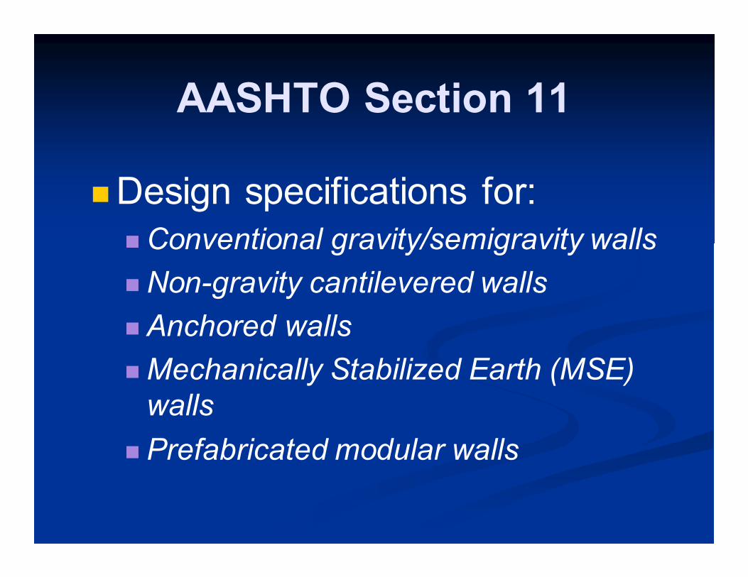
AASHTO Section 11
�Design specifications for:
� Conventional gravity/semigravity walls
� Non-gravity cantilevered walls
� Anchored walls
� Mechanically Stabilized Earth (MSE)
walls
� Prefabricated modular walls
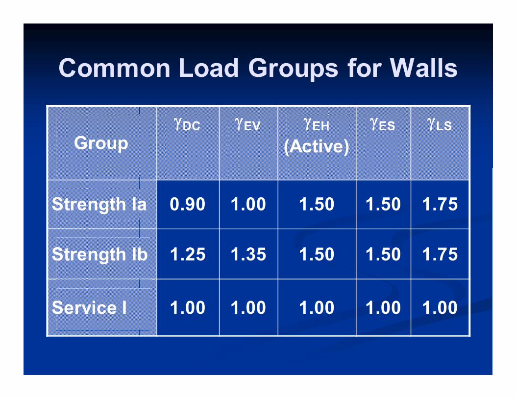
Common Load Groups for Walls
Group
γγγγDC γγγγEV γγγγEH
(Active)
γγγγES γγγγLS
Strength Ia 0.90 1.00 1.50 1.50 1.75
Strength Ib 1.25 1.35 1.50 1.50 1.75
Service I 1.00 1.00 1.00 1.00 1.00
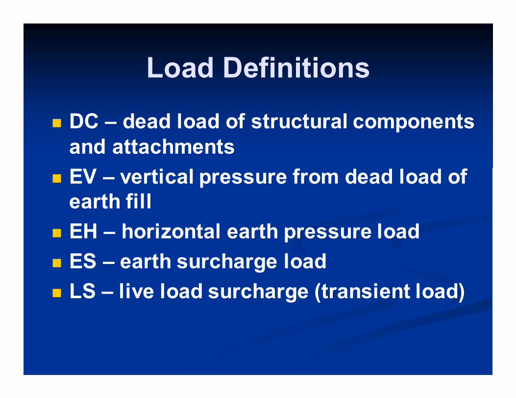
Load Definitions
� DC – dead load of structural components
and attachments
� EV – vertical pressure from dead load of
earth fill
� EH – horizontal earth pressure load
� ES – earth surcharge load
� LS – live load surcharge (transient load)
Surcharge Loads
� Earth surcharge AASHTO Section
3.11.6.1 and 3.11.6.2
� Live load surcharge AASHTO
3.11.6.4
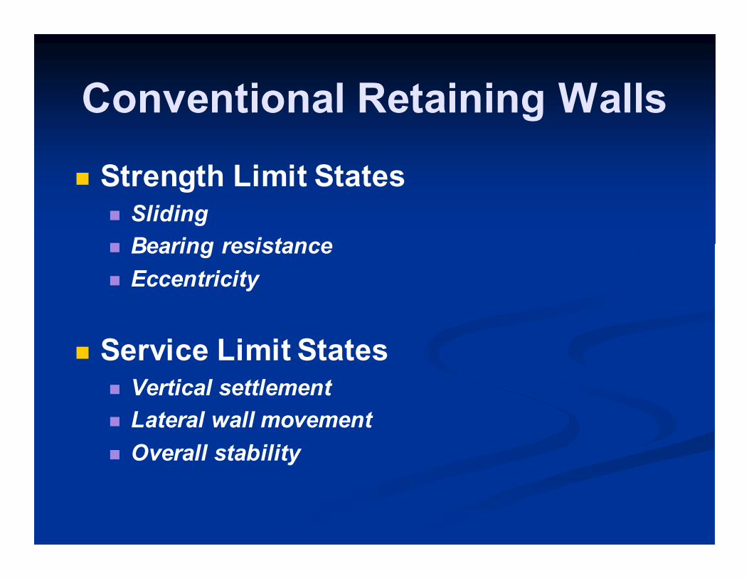
Conventional Retaining Walls
� Strength Limit States � Sliding
� Bearing resistance
� Eccentricity
� Service Limit States � Vertical settlement
� Lateral wall movement
� Overall stability
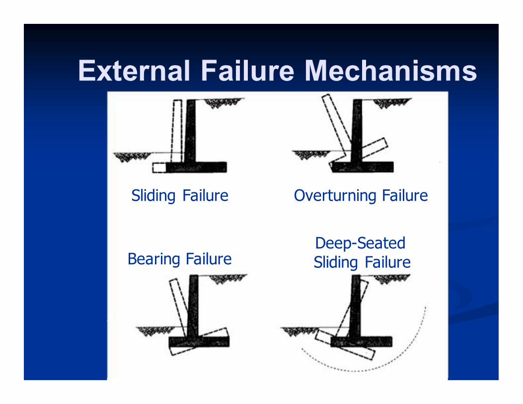
External Failure Mechanisms
Sliding Failure Overturning Failure
Bearing Failure Deep-Seated Sliding Failure
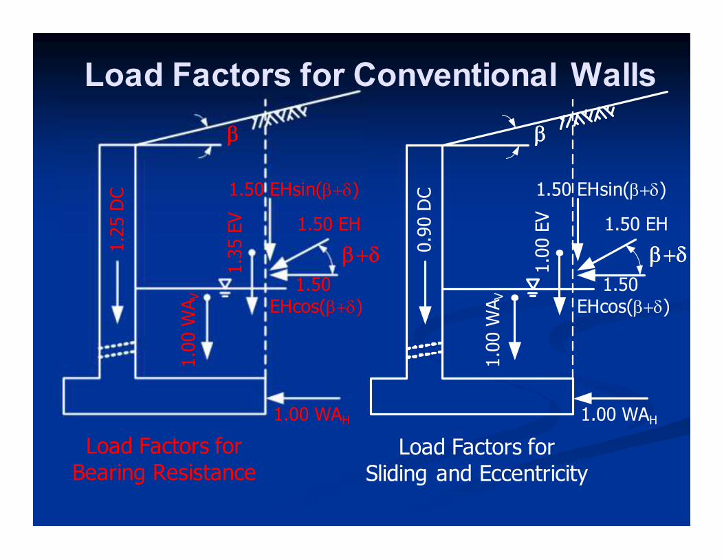
1.25 D
C
ββββ ββββ
0.90 D
C
1.00 W
AV
1.00 W
AV
β+δβ+δβ+δβ+δ β+δβ+δβ+δβ+δ 1.50
EHcos(β+δ) 1.50
EHcos(β+δ)
1.50 EH 1.50 EH 1.35 EV
1.00 EV
1.50 EHsin(β+δ) 1.50 EHsin(β+δ)
1.00 WAH 1.00 WAH
Load Factors for Bearing Resistance
Load Factors for Sliding and Eccentricity
Load Factors for Conventional Walls
Conventional Walls - Summary
� Use resistance factors for spread footings
or deep foundations, as appropriate
(Section 10.5)
� Eccentricity limited to:
� e/B < 0.25 for soil (compare to ASD 0.167)
� e/B < 0.375 for rock (compare to ASD 0.25)
Non-gravity Cantilevered Walls
� Strength Limit States � Bearing resistance of embedded portion of wall
� Passive resistance of embedded portion of wall
� Flexural resistance of wall/facing elements
� Service Limit States � Vertical wall movement
� Lateral wall movement
� Overall stability
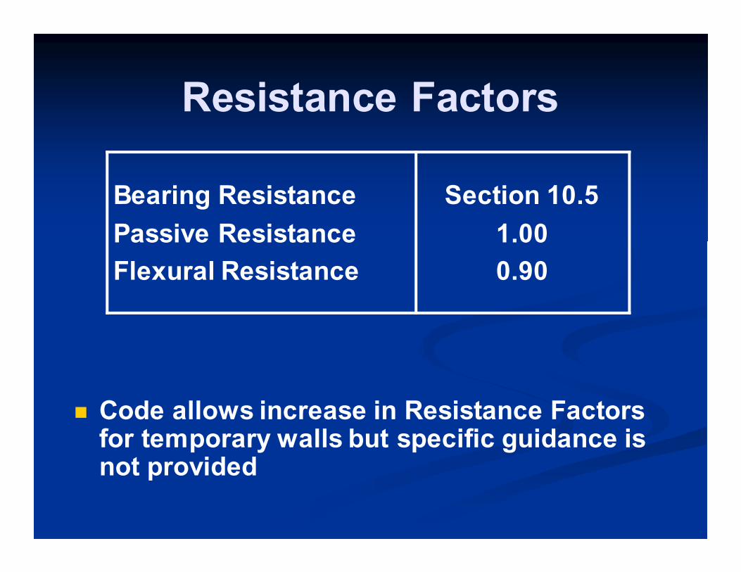
Resistance Factors
Bearing Resistance
Passive Resistance
Flexural Resistance
Section 10.5
1.00
0.90
� Code allows increase in Resistance Factors for temporary walls but specific guidance is not provided
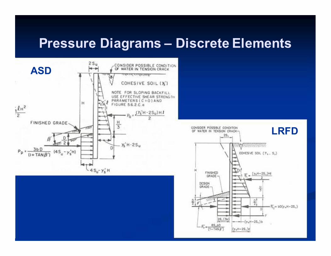
Pressure Diagrams – Discrete Elements
ASD
LRFD
Non-gravity Cantilevered Walls
� Below excavation line, multiply by 3b
on passive side of wall and 1b on active
side of wall for discrete elements
� Look at forces separately below
excavation line on passive side and
active side (because different load
factors)
� Factor embedment by 1.2 for
continuous wall elements
� Do not factor embedment for discrete
wall elements (conservatism of 3b
assumption)
Non-gravity Cantilevered Walls
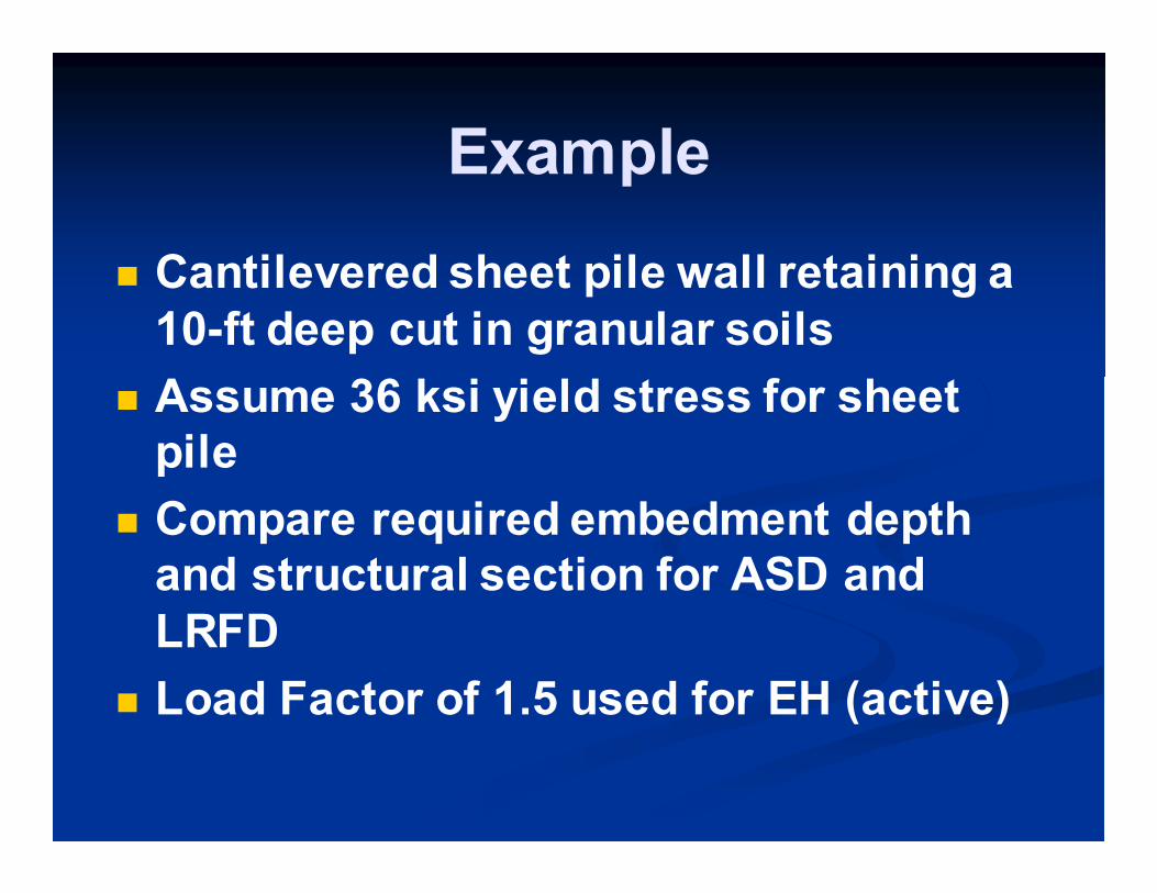
Example
� Cantilevered sheet pile wall retaining a
10-ft deep cut in granular soils
� Assume 36 ksi yield stress for sheet
pile
� Compare required embedment depth
and structural section for ASD and
LRFD
� Load Factor of 1.5 used for EH (active)
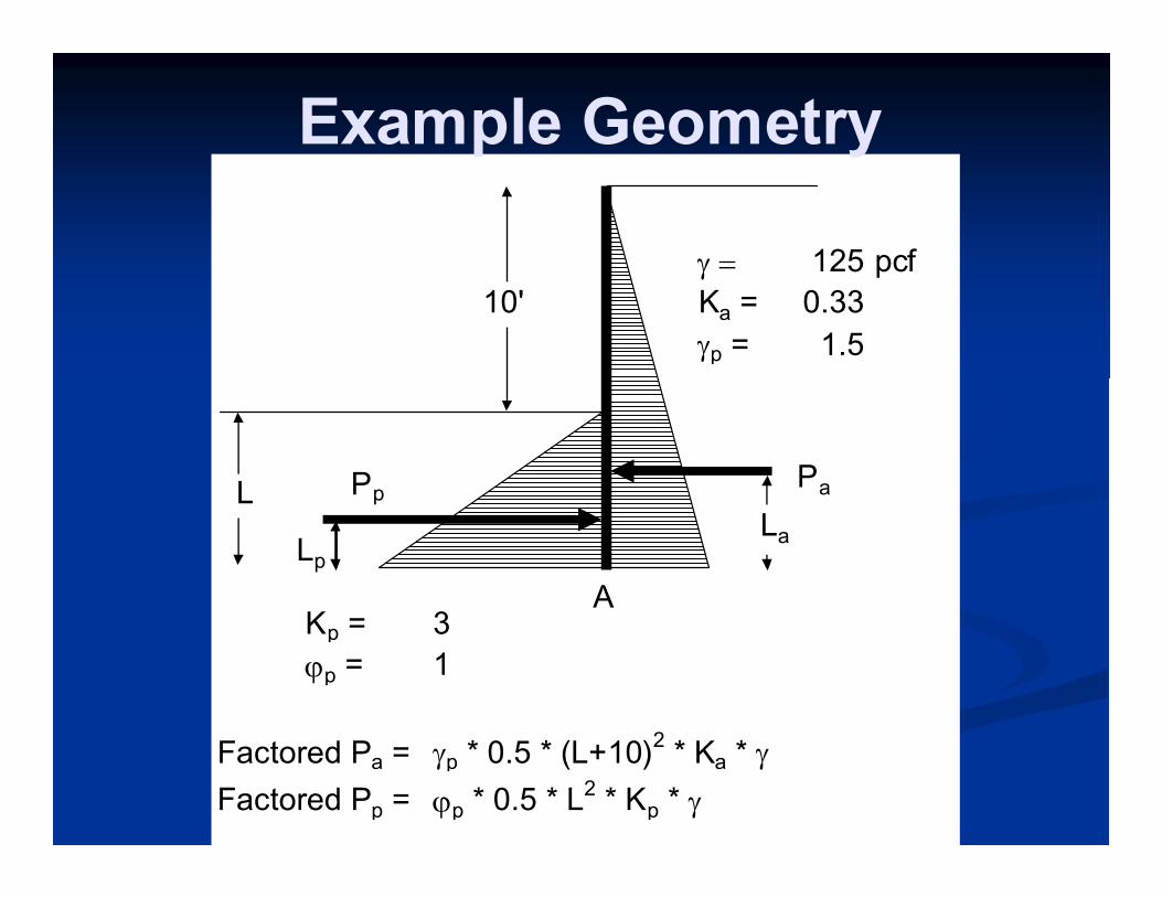
γ = 125 pcf
Ka = 0.33
γp = 1.5
Kp = 3
ϕp = 1
Factored Pa = γp * 0.5 * (L+10)2 * Ka * γ
Factored Pp = ϕp * 0.5 * L2 * Kp * γ
Pa
LpLa
L
A
10'
Pp
Example Geometry
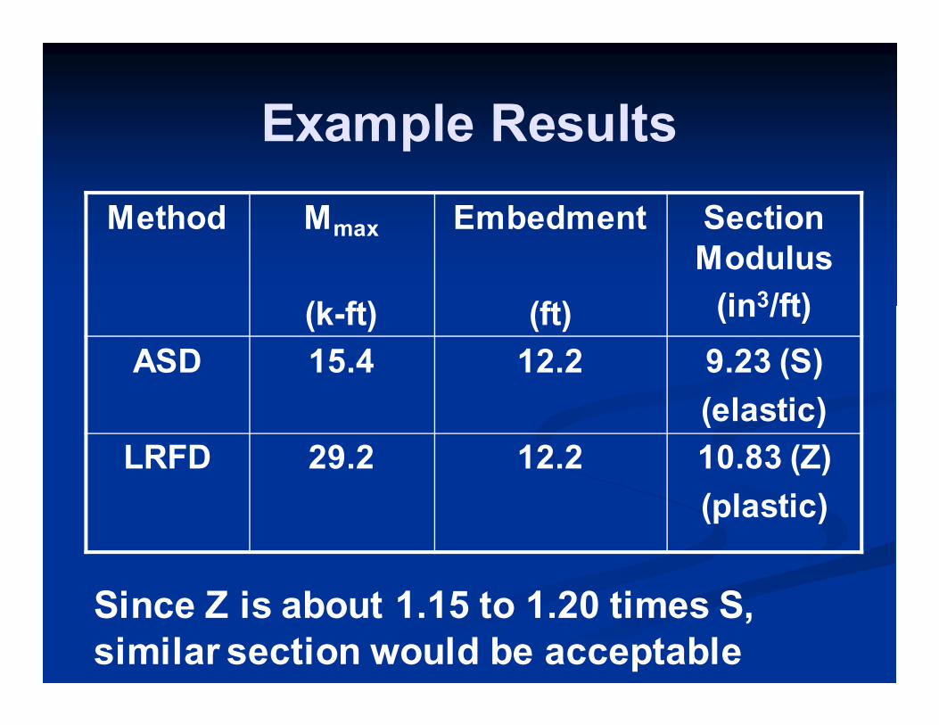
Example Results
Method Mmax
(k-ft)
Embedment
(ft)
Section
Modulus
(in3/ft)
ASD 15.4 12.2 9.23 (S)
(elastic)
LRFD 29.2 12.2 10.83 (Z)
(plastic)
Since Z is about 1.15 to 1.20 times S,
similar section would be acceptable
Anchored Walls
� Strength Limit States � Bearing resistance of embedded portion of wall
� Passive resistance of embedded portion of wall
� Flexural resistance of wall/facing elements
� Ground anchor pullout
� Tensile resistance of anchor tendon
� Service Limit States � Same as non-gravity cantilevered wall
Apparent Earth Pressure
Diagrams
� Based on FHWA-sponsored research
� Builds upon well-known Terzaghi-Peck
envelopes
� Appropriate for walls built in competent
ground where maximum wall height is
critical design case
� Same diagram shape for single or
multi-leveled anchored walls
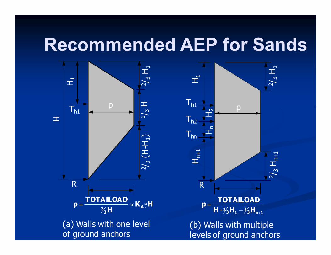
Recommended AEP for Sands H
H1
H1
Hn+1
p p
2/ 3 H
1
2/ 3 H
1
2/ 3 H
n+1
2/ 3 (H-H
1)
1/ 3 H
Th1
Th1
Th2
Thn
H2
Hn
R R
(a) Walls with one level of ground anchors
(b) Walls with multiple levels of ground anchors
HKH
LOADTOTALp A
32
γ≈=1n3
113
1 HH-H
LOADTOTALp
+−=
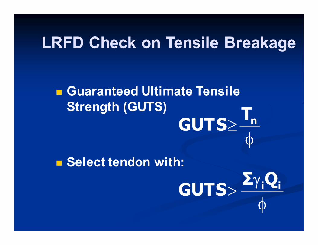
� Guaranteed Ultimate Tensile
Strength (GUTS)
� Select tendon with:
φ≥ nT
GUTS
φ> iiQΣ
GUTSγ
LRFD Check on Tensile Breakage
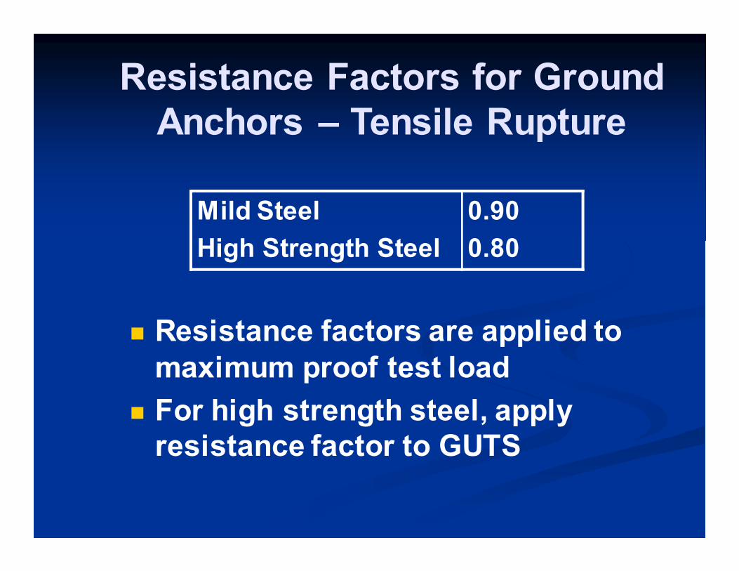
Resistance Factors for Ground
Anchors – Tensile Rupture
� Resistance factors are applied to
maximum proof test load
� For high strength steel, apply
resistance factor to GUTS
Mild Steel 0.90
High Strength Steel 0.80
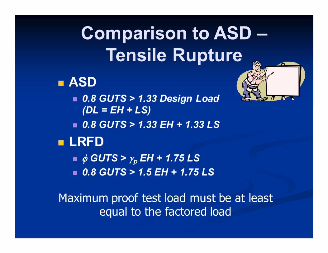
Comparison to ASD –
Tensile Rupture
� ASD � 0.8 GUTS > 1.33 Design Load
(DL = EH + LS)
� 0.8 GUTS > 1.33 EH + 1.33 LS
� LRFD � φφφφ GUTS > γγγγp EH + 1.75 LS
� 0.8 GUTS > 1.5 EH + 1.75 LS
Maximum proof test load must be at least equal to the factored load
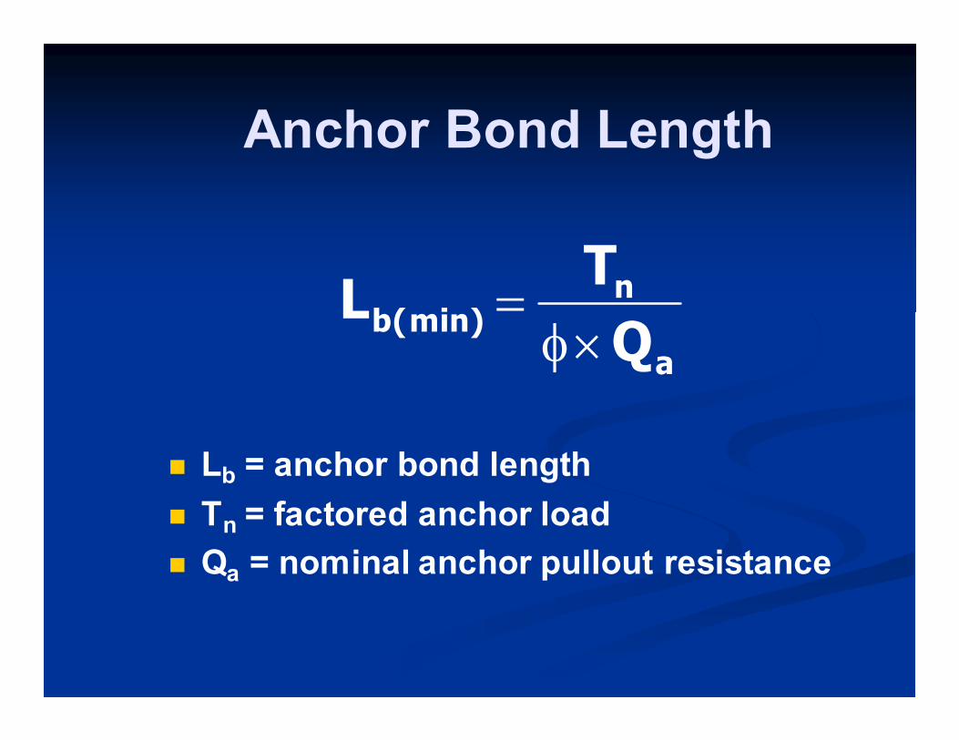
Anchor Bond Length
a
nb(min)
Q
TL
×φ=
� Lb = anchor bond length
� Tn = factored anchor load
� Qa = nominal anchor pullout resistance
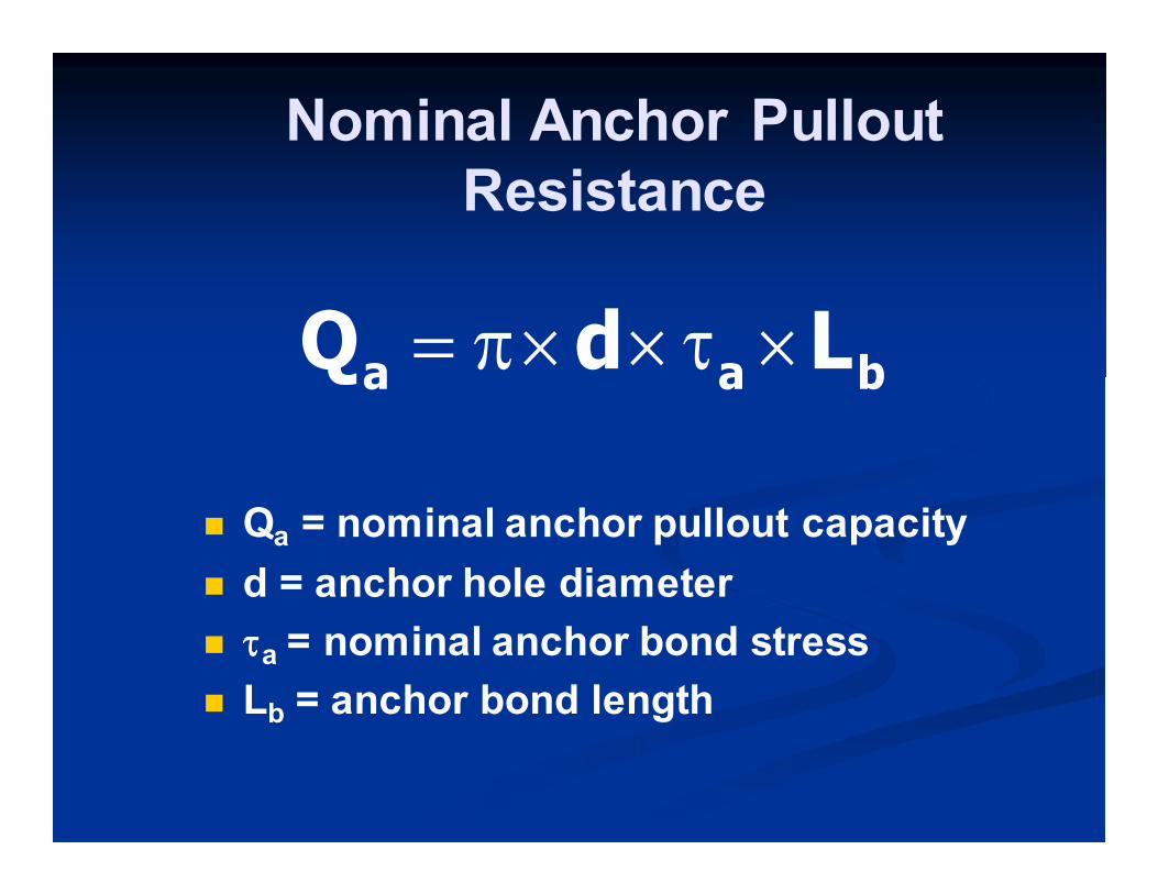
Nominal Anchor Pullout
Resistance
baa LdQ ×τ××π=
� Qa = nominal anchor pullout capacity
� d = anchor hole diameter
� ττττa = nominal anchor bond stress
� Lb = anchor bond length
Preliminary Evaluation Only
� Bond stress values in AASHTO should be used for FEASIBILITY evaluation
� AASHTO values for cohesionless and cohesive soil and rock
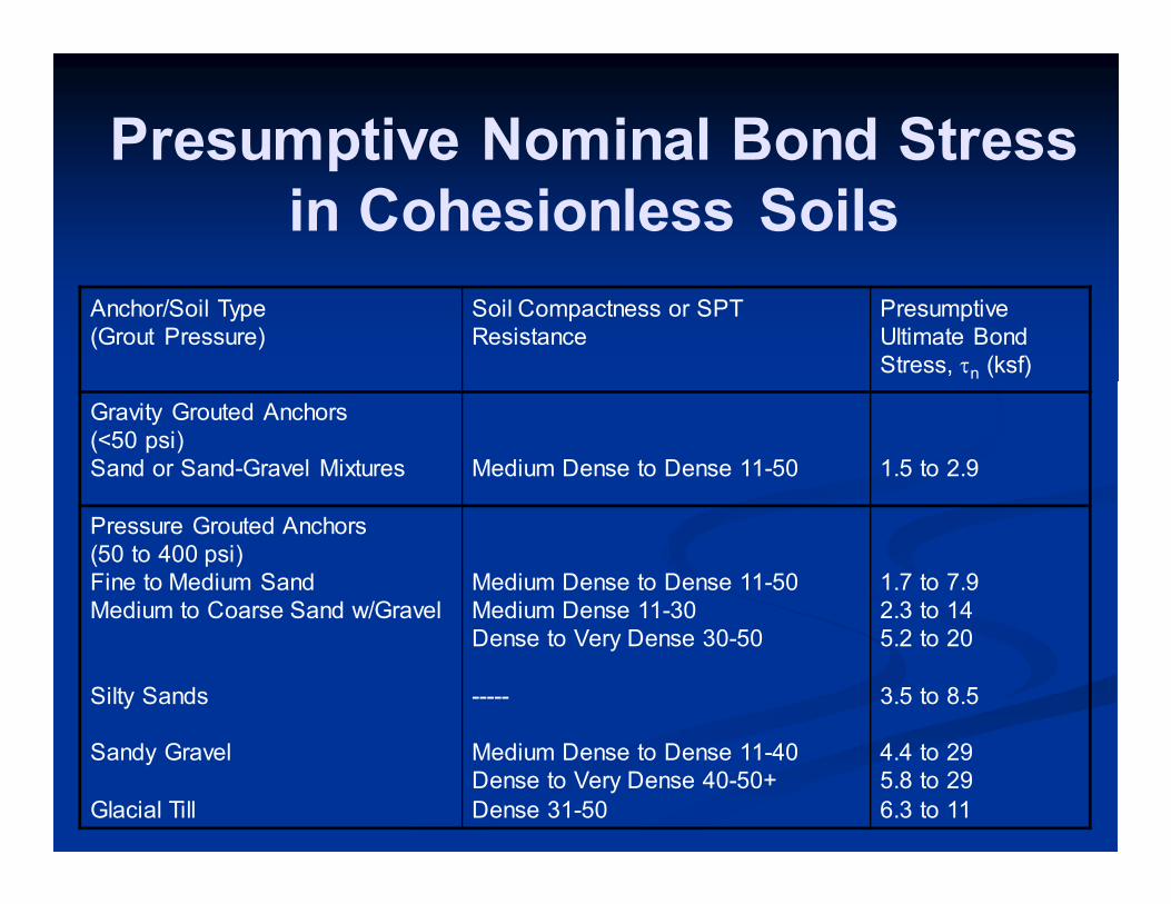
Anchor/Soil Type
(Grout Pressure)
Soil Compactness or SPT
Resistance
Presumptive
Ultimate Bond
Stress, τn (ksf)
Gravity Grouted Anchors
(<50 psi)
Sand or Sand-Gravel Mixtures
Medium Dense to Dense 11-50
1.5 to 2.9
Pressure Grouted Anchors
(50 to 400 psi)
Fine to Medium Sand
Medium to Coarse Sand w/Gravel
Silty Sands
Sandy Gravel
Glacial Till
Medium Dense to Dense 11-50
Medium Dense 11-30
Dense to Very Dense 30-50
-----
Medium Dense to Dense 11-40
Dense to Very Dense 40-50+
Dense 31-50
1.7 to 7.9
2.3 to 14
5.2 to 20
3.5 to 8.5
4.4 to 29
5.8 to 29
6.3 to 11
Presumptive Nominal Bond Stress
in Cohesionless Soils
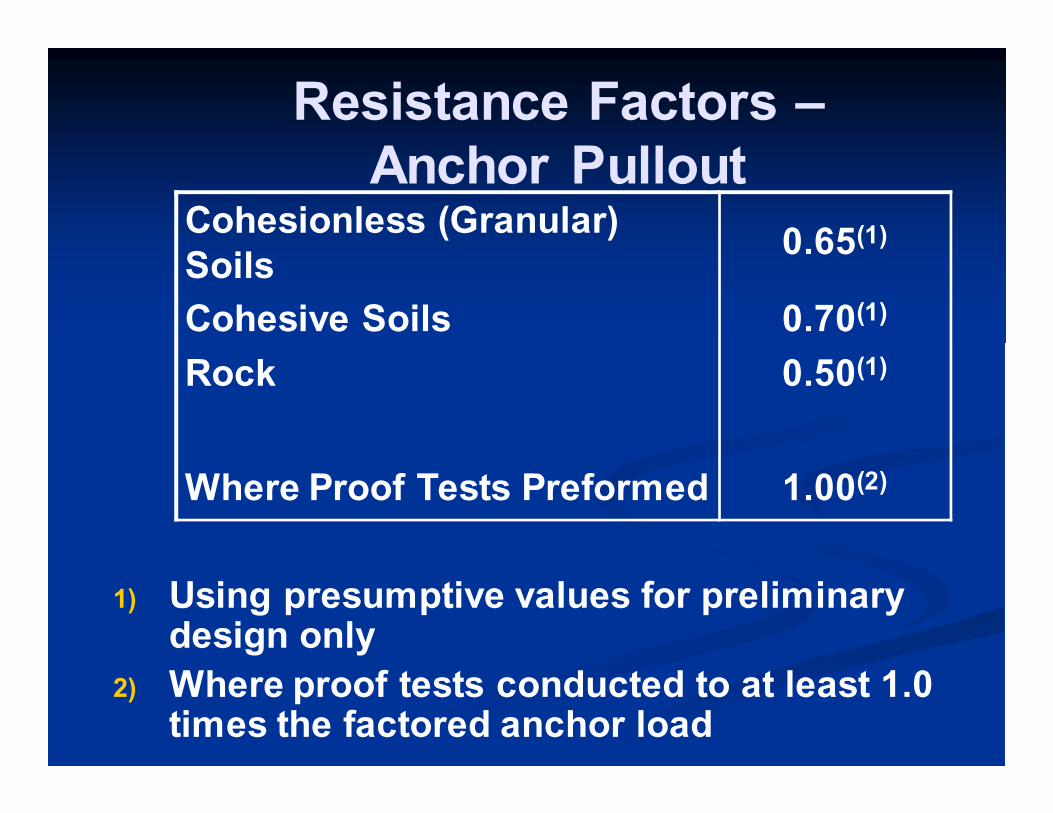
Resistance Factors –
Anchor Pullout
1) Using presumptive values for preliminary design only
2) Where proof tests conducted to at least 1.0 times the factored anchor load
Cohesionless (Granular)
Soils 0.65(1)
Cohesive Soils 0.70(1)
Rock 0.50(1)
Where Proof Tests Preformed 1.00(2)
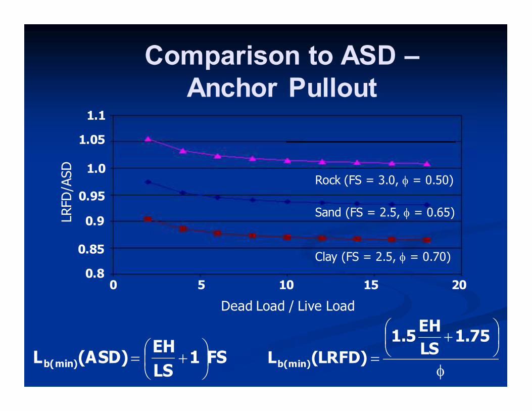
FS1LS
EH(ASD)Lb(min)
+=φ
+
=1.75
LS
EH1.5
(LRFD)Lb(min)
LRFD/A
SD
1.05
1.1
1.0
0.95
0.9
0.85
0.8 0 5 10 15 20
Dead Load / Live Load
Rock (FS = 3.0, φ = 0.50)
Sand (FS = 2.5, φ = 0.65)
Clay (FS = 2.5, φ = 0.70)
Comparison to ASD –
Anchor Pullout
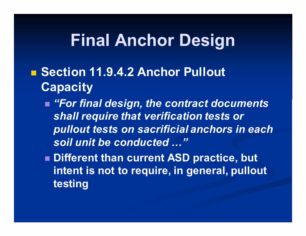
Final Anchor Design
� Section 11.9.4.2 Anchor Pullout
Capacity
� “For final design, the contract documents
shall require that verification tests or
pullout tests on sacrificial anchors in each
soil unit be conducted ;”
� Different than current ASD practice, but
intent is not to require, in general, pullout
testing
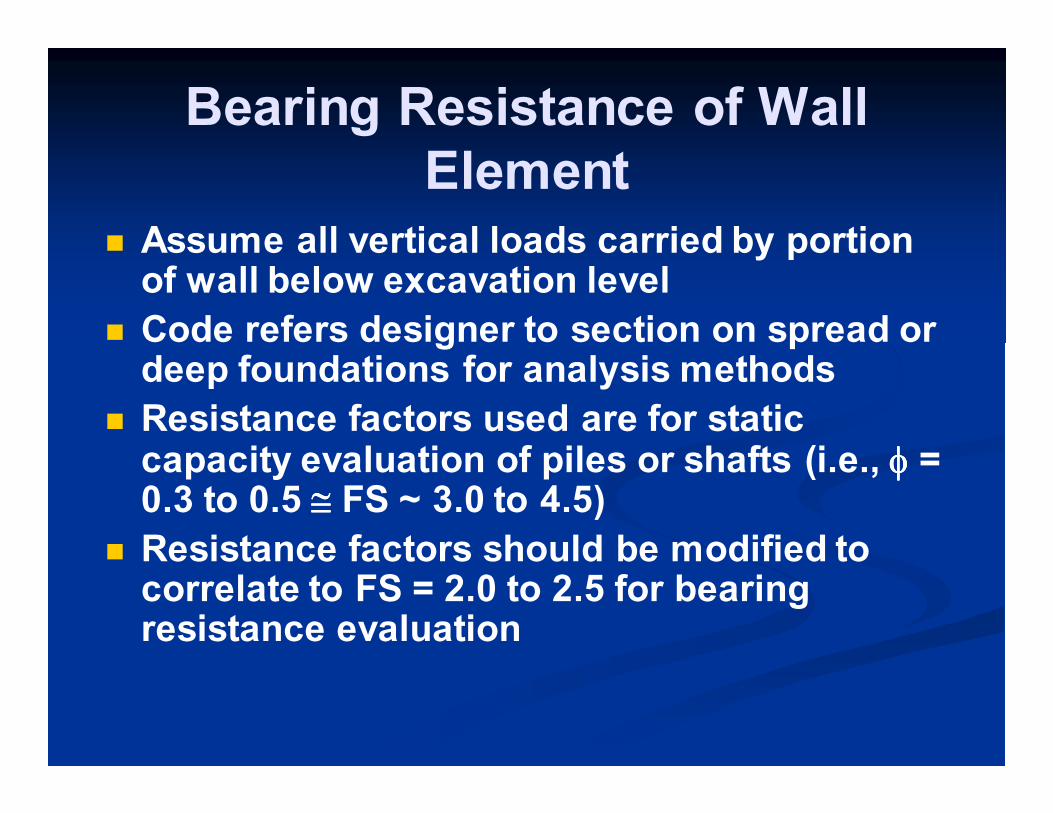
Bearing Resistance of Wall
Element
� Assume all vertical loads carried by portion of wall below excavation level
� Code refers designer to section on spread or deep foundations for analysis methods
� Resistance factors used are for static capacity evaluation of piles or shafts (i.e., φφφφ = 0.3 to 0.5 ≅≅≅≅ FS ~ 3.0 to 4.5)
� Resistance factors should be modified to correlate to FS = 2.0 to 2.5 for bearing resistance evaluation
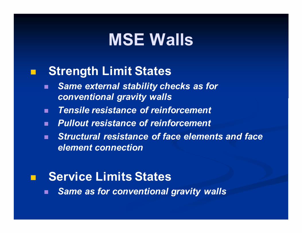
MSE Walls
� Strength Limit States � Same external stability checks as for
conventional gravity walls
� Tensile resistance of reinforcement
� Pullout resistance of reinforcement
� Structural resistance of face elements and face
element connection
� Service Limits States � Same as for conventional gravity walls
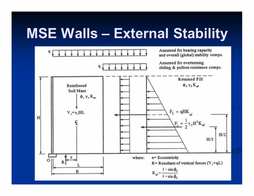
MSE Walls – External Stability
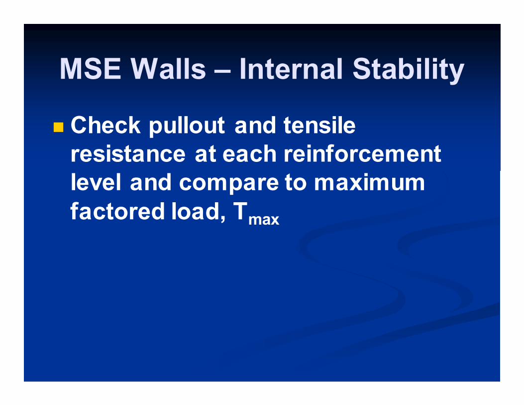
MSE Walls – Internal Stability
� Check pullout and tensile
resistance at each reinforcement
level and compare to maximum
factored load, Tmax
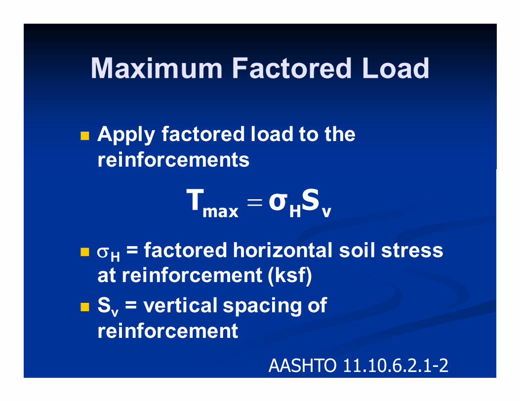
� Apply factored load to the
reinforcements
� σσσσH = factored horizontal soil stress
at reinforcement (ksf)
� Sv = vertical spacing of
reinforcement
vHmax SσT =
AASHTO 11.10.6.2.1-2
Maximum Factored Load
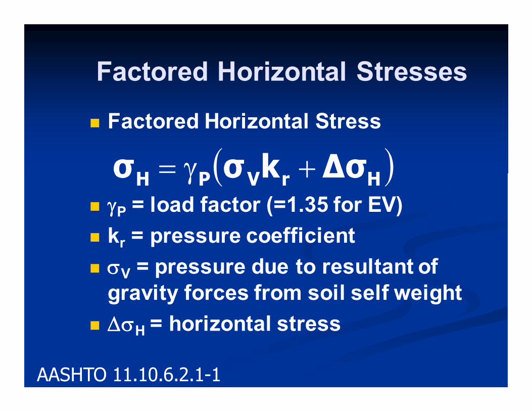
Factored Horizontal Stresses
� Factored Horizontal Stress
� γγγγP = load factor (=1.35 for EV)
� kr = pressure coefficient
� σσσσV = pressure due to resultant of
gravity forces from soil self weight
� ∆σ∆σ∆σ∆σH = horizontal stress
( )HrVPH ∆σkσσ +γ=
AASHTO 11.10.6.2.1-1
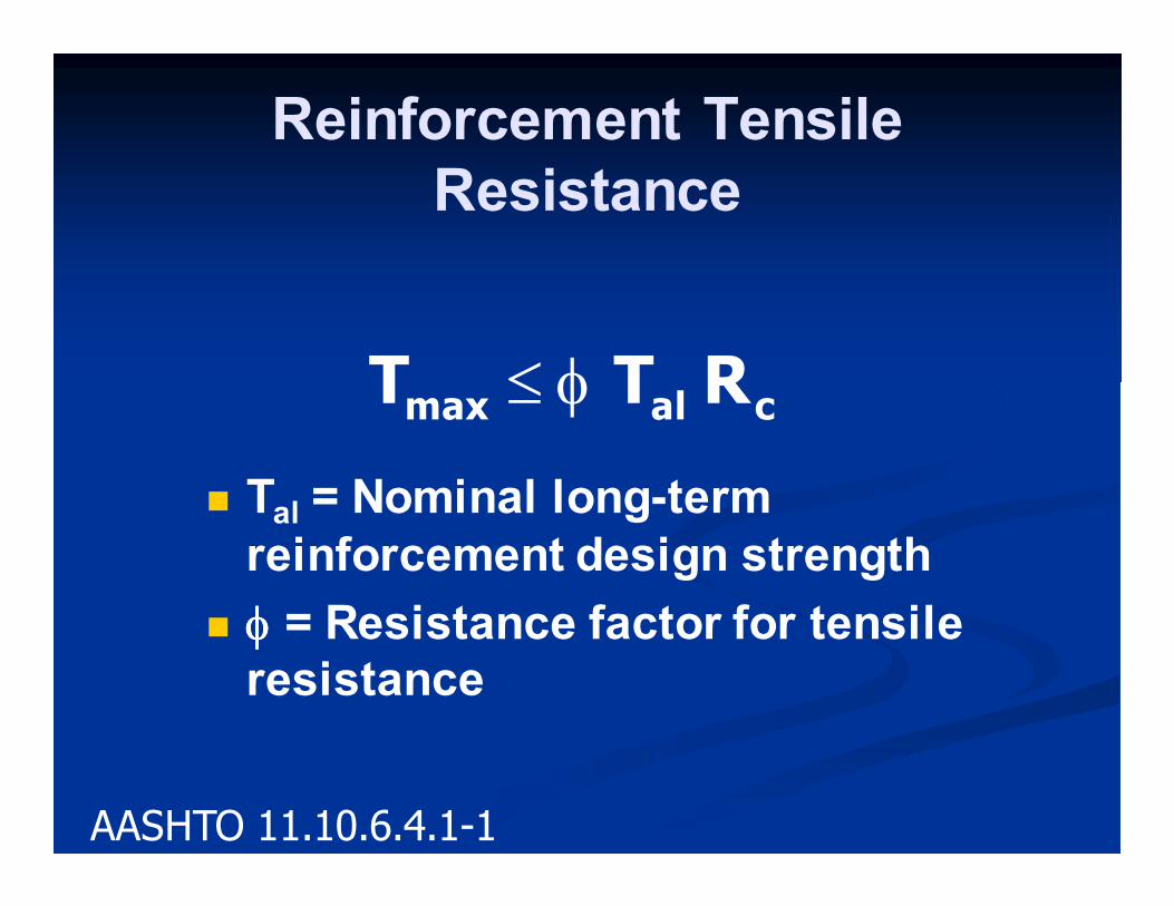
� Tal = Nominal long-term
reinforcement design strength
� φφφφ = Resistance factor for tensile
resistance
calmax RTT φ≤
AASHTO 11.10.6.4.1-1
Reinforcement Tensile
Resistance
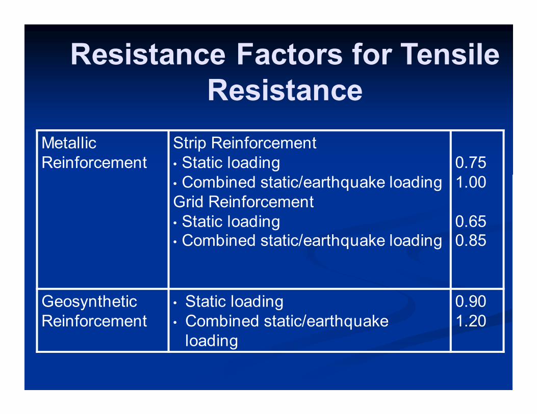
Resistance Factors for Tensile
Resistance
Metallic
Reinforcement
Strip Reinforcement
• Static loading
• Combined static/earthquake loading
Grid Reinforcement
• Static loading • Combined static/earthquake loading
0.75
1.00
0.65 0.85
Geosynthetic
Reinforcement
• Static loading
• Combined static/earthquake
loading
0.90
1.20
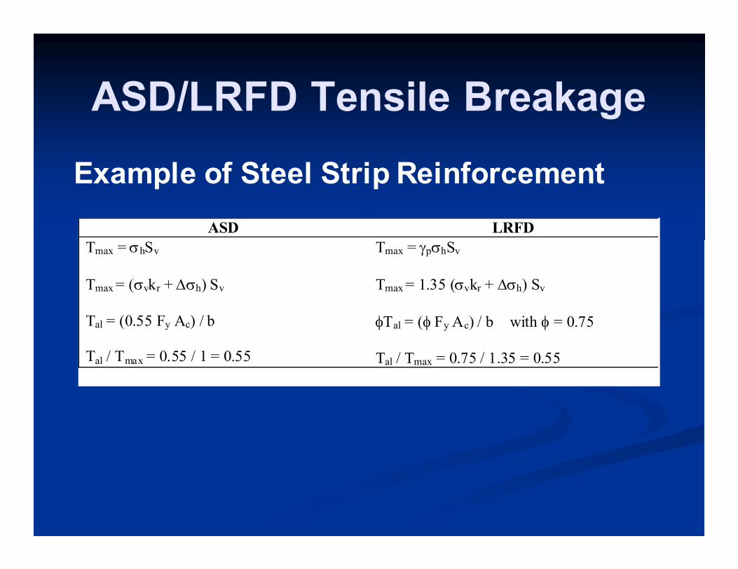
ASD/LRFD Tensile Breakage
Example of Steel Strip Reinforcement
ASD LRFD
Tmax = σhSv
Tmax = (σvkr + ∆σh) Sv
Tal = (0.55 Fy Ac) / b Tal / Tmax = 0.55 / 1 = 0.55
Tmax = γpσhSv
Tmax = 1.35 (σvkr + ∆σh) Sv
φTal = (φ Fy Ac) / b with φ = 0.75
Tal / Tmax = 0.75 / 1.35 = 0.55

Other Developments
� LRFD for Soil Nails – NCHRP 24-21
� Draft LRFD Design and Construction
Specification for Micropiles
? The
End