AASHTO T-14 2018 Agenda Items...T-14 Agenda Item No. 21 Section 6, Table 6.6.1.2.3-1 and Article...
16
AASHTO T-14 2018 Agenda Items Proposed Revisions to LRFD BDS Section 6 Michael A. Grubb, P.E. M.A. Grubb & Associates, LLC Wexford, PA
Transcript of AASHTO T-14 2018 Agenda Items...T-14 Agenda Item No. 21 Section 6, Table 6.6.1.2.3-1 and Article...
AASHTO T-142018 Agenda ItemsProposed Revisions to LRFD BDS Section 6
Michael A. Grubb, P.E.
M.A. Grubb & Associates, LLC
Wexford, PA
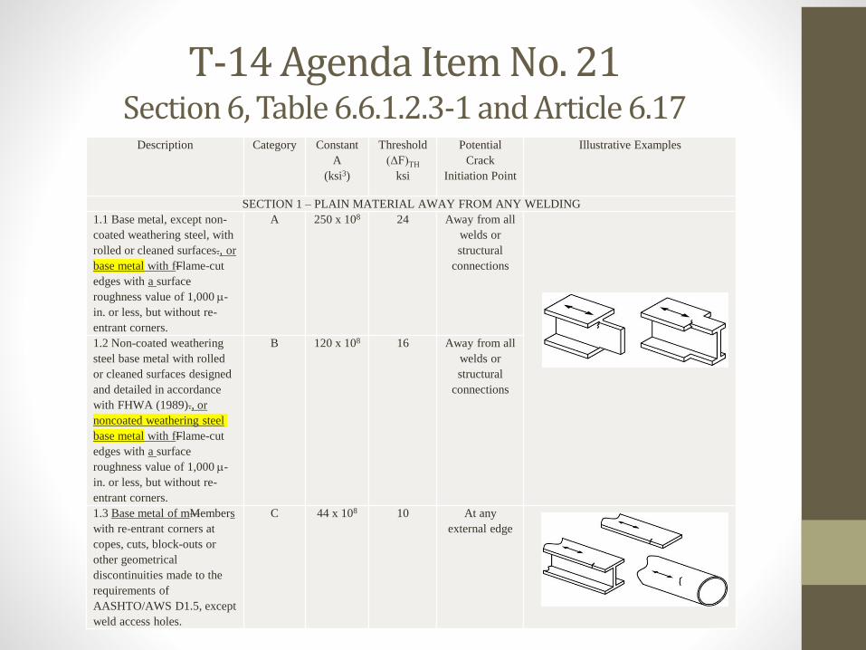
T-14 Agenda Item No. 21 Section 6, Table 6.6.1.2.3-1 and Article 6.17
Description Category Constant
A
(ksi3)
Threshold
(ΔF)TH
ksi
Potential
Crack
Initiation Point
Illustrative Examples
SECTION 1 – PLAIN MATERIAL AWAY FROM ANY WELDING
1.1 Base metal, except non-
coated weathering steel, with
rolled or cleaned surfaces., or
base metal with fFlame-cut
edges with a surface
roughness value of 1,000 -
in. or less, but without re-
entrant corners.
A 250 x 108 24 Away from all
welds or
structural
connections
1.2 Non-coated weathering
steel base metal with rolled
or cleaned surfaces designed
and detailed in accordance
with FHWA (1989)., or
noncoated weathering steel
base metal with fFlame-cut
edges with a surface
roughness value of 1,000 -
in. or less, but without re-
entrant corners.
B 120 x 108 16 Away from all
welds or
structural
connections
1.3 Base metal of mMembers
with re-entrant corners at
copes, cuts, block-outs or
other geometrical
discontinuities made to the
requirements of
AASHTO/AWS D1.5, except
weld access holes.
C 44 x 108 10 At any
external edge
T-14 Agenda Item No. 21Section 6, Table 6.6.1.2.3-1 and Article 6.17
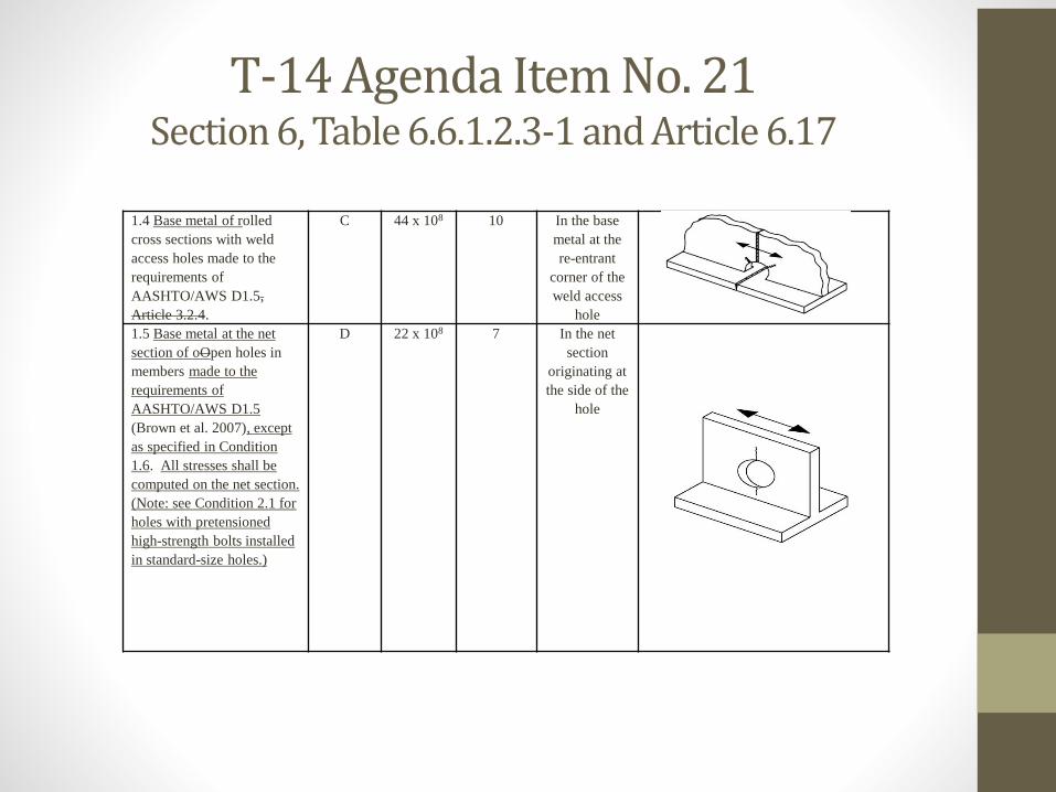
1.4 Base metal of rolled
cross sections with weld
access holes made to the
requirements of
AASHTO/AWS D1.5,
Article 3.2.4.
C 44 x 108 10 In the base
metal at the
re-entrant
corner of the
weld access
hole
1.5 Base metal at the net
section of oOpen holes in
members made to the
requirements of
AASHTO/AWS D1.5
(Brown et al. 2007), except
as specified in Condition
1.6. All stresses shall be
computed on the net section.
(Note: see Condition 2.1 for
holes with pretensioned
high-strength bolts installed
in standard-size holes.)
D 22 x 108 7 In the net
section
originating at
the side of the
hole
T-14 Agenda Item No. 21Section 6, Table 6.6.1.2.3-1 and Article 6.17
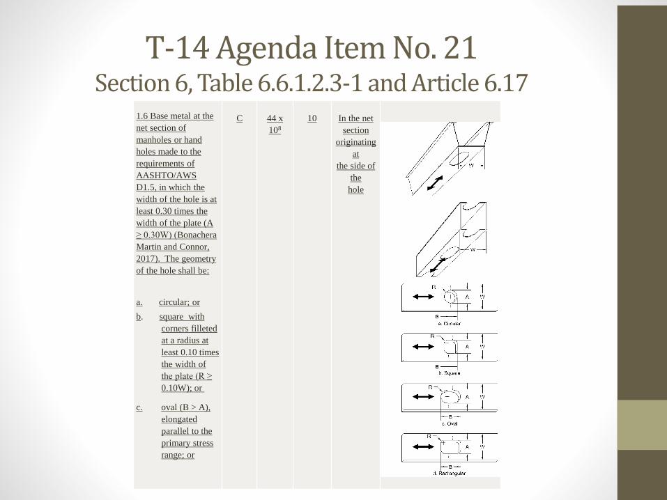
1.6 Base metal at the
net section of
manholes or hand
holes made to the
requirements of
AASHTO/AWS
D1.5, in which the
width of the hole is at
least 0.30 times the
width of the plate (A
≥ 0.30W) (Bonachera
Martin and Connor,
2017). The geometry
of the hole shall be:
a. circular; or
b. square with
corners filleted
at a radius at
least 0.10 times
the width of
the plate (R ≥
0.10W); or
c. oval (B > A),
elongated
parallel to the
primary stress
range; or
C 44 x
108
10 In the net
section
originating
at
the side of
the
hole
T-14 Agenda Item No. 21Section 6, Table 6.6.1.2.3-1 and Article 6.17
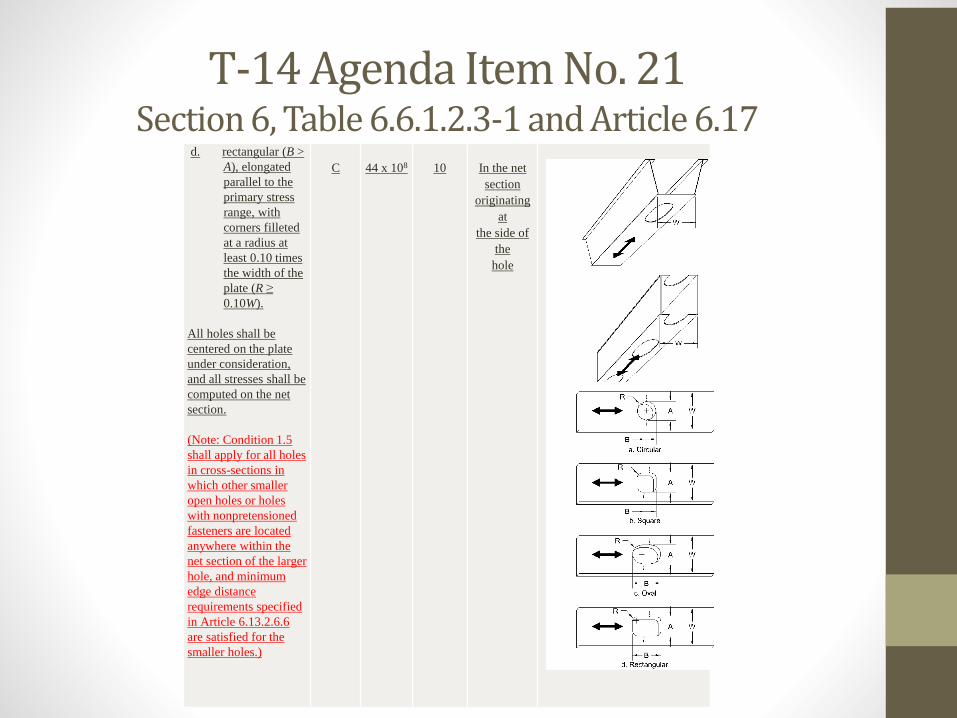
d. rectangular (B >
A), elongated
parallel to the
primary stress
range, with
corners filleted
at a radius at
least 0.10 times
the width of the
plate (R ≥
0.10W).
All holes shall be
centered on the plate
under consideration,
and all stresses shall be
computed on the net
section.
(Note: Condition 1.5
shall apply for all holes
in cross-sections in
which other smaller
open holes or holes
with nonpretensioned
fasteners are located
anywhere within the
net section of the larger
hole, and minimum
edge distance
requirements specified
in Article 6.13.2.6.6
are satisfied for the
smaller holes.)
C 44 x 108 10 In the net
section
originating
at
the side of
the
hole
T-14 Agenda Item No. 22 Section 6, Article C6.6.2.1 and 6.6.2.2
• Description of Proposed Revisions:
• Item #1:Article C6.6.2.1 (6th paragraph) - clarify the designations for the
steel grades in AASHTO M270M/M270 (ASTM A709/A709M) subject to Charpy V-notch testing requirements as follows:
The Charpy V-notch impact energy requirements, specified in AASHTO M 270M/M 270 (ASTM A709/A709M) and shown in Table C6.6.2.1-1, vary depending on the grade of steel, and the applicable minimum service temperature. FCMs are subject to more stringent Charpy V-notch impact energy requirements than nonfracture-critical components. Steel grades for nonfracture-critical tension members or components subject to Charpy V-notch testing should be orderedare designated with the suffix T in AASHTO M 270M/M 270 (ASTM A709/A709M), and steel grades for fracture-critical tension members or components subject to Charpy V-notch testing should be orderedare designated with the suffix F.
T-14 Agenda Item No. 22 Section 6, Article C6.6.2.1 and 6.6.2.2
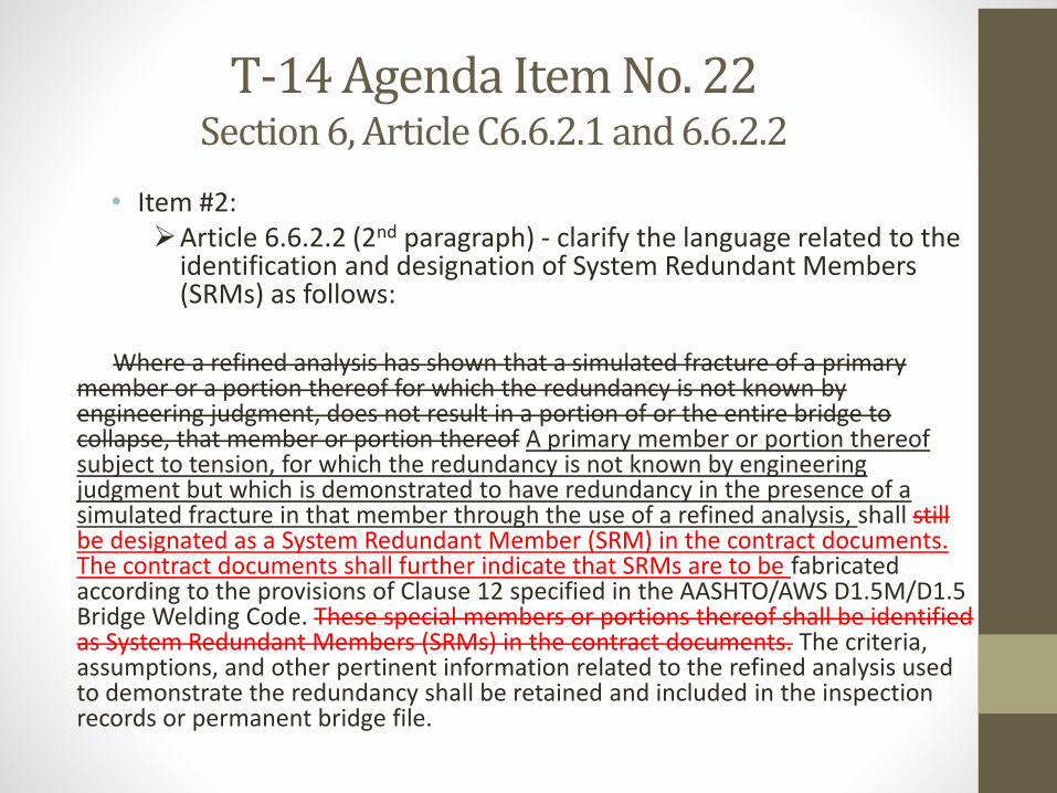
• Item #2:Article 6.6.2.2 (2nd paragraph) - clarify the language related to the
identification and designation of System Redundant Members (SRMs) as follows:
Where a refined analysis has shown that a simulated fracture of a primary member or a portion thereof for which the redundancy is not known by engineering judgment, does not result in a portion of or the entire bridge to collapse, that member or portion thereof A primary member or portion thereof subject to tension, for which the redundancy is not known by engineering judgment but which is demonstrated to have redundancy in the presence of a simulated fracture in that member through the use of a refined analysis, shall still be designated as a System Redundant Member (SRM) in the contract documents. The contract documents shall further indicate that SRMs are to be fabricated according to the provisions of Clause 12 specified in the AASHTO/AWS D1.5M/D1.5 Bridge Welding Code. These special members or portions thereof shall be identified as System Redundant Members (SRMs) in the contract documents. The criteria, assumptions, and other pertinent information related to the refined analysis used to demonstrate the redundancy shall be retained and included in the inspection records or permanent bridge file.
T-14 Agenda Item No. 22 Section 6, Article C6.6.2.1 and 6.6.2.2
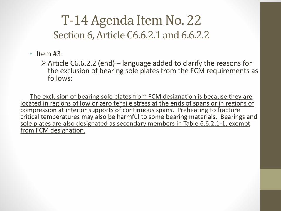
• Item #3:Article C6.6.2.2 (end) – language added to clarify the reasons for
the exclusion of bearing sole plates from the FCM requirements as follows:
The exclusion of bearing sole plates from FCM designation is because they are located in regions of low or zero tensile stress at the ends of spans or in regions of compression at interior supports of continuous spans. Preheating to fracture critical temperatures may also be harmful to some bearing materials. Bearings and sole plates are also designated as secondary members in Table 6.6.2.1-1, exempt from FCM designation.
T-14 Agenda Item No. 23 Section 6, Article 6.13.2.5
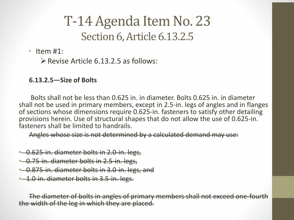
• Item #1:Revise Article 6.13.2.5 as follows:
6.13.2.5—Size of Bolts
Bolts shall not be less than 0.625 in. in diameter. Bolts 0.625 in. in diameter shall not be used in primary members, except in 2.5-in. legs of angles and in flanges of sections whose dimensions require 0.625-in. fasteners to satisfy other detailing provisions herein. Use of structural shapes that do not allow the use of 0.625-in. fasteners shall be limited to handrails.
Angles whose size is not determined by a calculated demand may use:
• 0.625-in. diameter bolts in 2.0-in. legs,• 0.75-in. diameter bolts in 2.5-in. legs,• 0.875-in. diameter bolts in 3.0-in. legs, and• 1.0-in. diameter bolts in 3.5-in. legs.
The diameter of bolts in angles of primary members shall not exceed one-fourth the width of the leg in which they are placed.
T-14 Agenda Item No. 24 Section 6, Various Articles
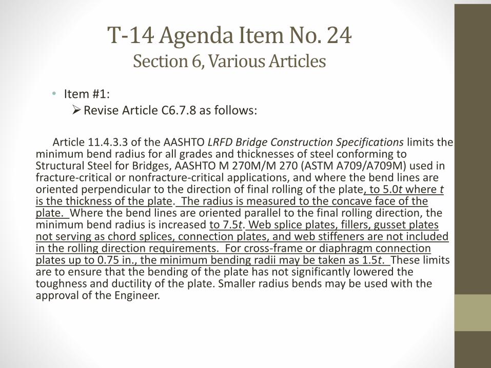
• Item #1:Revise Article C6.7.8 as follows:
Article 11.4.3.3 of the AASHTO LRFD Bridge Construction Specifications limits the minimum bend radius for all grades and thicknesses of steel conforming to Structural Steel for Bridges, AASHTO M 270M/M 270 (ASTM A709/A709M) used in fracture-critical or nonfracture-critical applications, and where the bend lines are oriented perpendicular to the direction of final rolling of the plate, to 5.0t where tis the thickness of the plate. The radius is measured to the concave face of the plate. Where the bend lines are oriented parallel to the final rolling direction, the minimum bend radius is increased to 7.5t. Web splice plates, fillers, gusset plates not serving as chord splices, connection plates, and web stiffeners are not included in the rolling direction requirements. For cross-frame or diaphragm connection plates up to 0.75 in., the minimum bending radii may be taken as 1.5t. These limits are to ensure that the bending of the plate has not significantly lowered the toughness and ductility of the plate. Smaller radius bends may be used with the approval of the Engineer.
T-14 Agenda Item No. 24Section 6, Various Articles
• Item #2:Revise the 8th paragraph of Article 6.13.6.1.3c as follows:
Webs shall be spliced symmetrically by plates on each side. The splice plates shall extend as near as practical for the full depth between flanges without impinging on bolt assembly clearances or fillet areas on rolled beams. For bolted web splices with thickness differences of 0.0625 in. or less, filler plates should not be provided.
T-14 Agenda Item No. 24 Section 6, Various Articles
• Item #3:Revise the 3rd paragraph of Article 6.13.6.1.4 as follows:
Fillers 0.25 in. or more in thickness shall consist of not more than two plates, unless approved by the Engineer. The actual total filler thickness may exceed the total filler thickness shown in the contract documents by up to a maximum of 0.25 in.
Add the following paragraph after the 3rd paragraph of Article C6.13.6.1.4:
A tolerance of up to 0.25 in. on the total filler thickness is permitted should fabrication or rolling tolerances require the use of an additional filler not shown in the contract documents in order to adequately mate the fillers with the outer surface of the flange on the other side of the splice. A reduction in the specified filler thickness is permitted without restriction. Test results (Frank and Yura, 1981; Dusicka and Lewis, 2010) have shown that a 0.25-in-thick filler does not significantly reduce the resistance of the connection.
T-14/T-4/T-18 Agenda Item No. 25Section 11, Articles C11.9.1 and 11.9.2
• Item #1:Revise the 2nd paragraph of Article C11.9.1 as follows:
Based on research performed at Lehigh University, the fatigue strength of welded connections can be improved by post weld Ultrasonic Impact Treatment (S. Roy, et al., 2005; S. Roy, and J.W. Fisher, 2005).
Research performed at Lehigh University showed has shown that the fatigue strength of welded connections can be improved by post-weld 27 kHz Ultrasonic Impact Treatment (Roy et al., 2005; Roy and Fisher, 2005). Subsequent research performed at Purdue University showed has shown that post-weld 20 kHz Ultrasonic Impact Treatment has equivalent effectiveness (Hui et al., 2018). In general, the objective of UIT is to plastically deform the material at the weld toes and introduce residual compressive stresses substantially greater than the largest anticipated tensile stresses to a depth of no less than 0.02 in. (0.5 mm).
T-14/T-4/T-18 Agenda Item No. 25 Section 11, Articles C11.9.1 and 11.9.2
Revise the 4th paragraph of Article C11.9.1 as follows:
To successfully accomplish the treatment, the following sample procedure should be included in the special provisions of the contract documents, unless otherwise recommended by the UIT equipment Manufacturer: The following is a sample procedure for a particular 27 kHz Ultrasonic Impact Treatment system. Due to the proprietary nature of UIT, operating parameters may vary depending on equipment manufacturer. Whether a 20 kHz or 27 kHz system is selected, the treatment should be carried out following the equipment manufacturer’s recommended practices.
Note: removed all occurrences of “shall” and “must” in the description of the sample procedure.
• Item #2:Revise the 4th paragraph of Article 11.9.2 as follows:
Prior to UIT, the weld toe to receive UIT shall be visually inspected and magnetic particle-tested for conformance to the quality standards specified in the contract documents. The instrument shall be calibrated against the maximum flaw size allowed.Surface cracks Discontinuities greater than 1/32 in. (0.79 mm) shall be repaired satisfactorily prior to initiating the work.
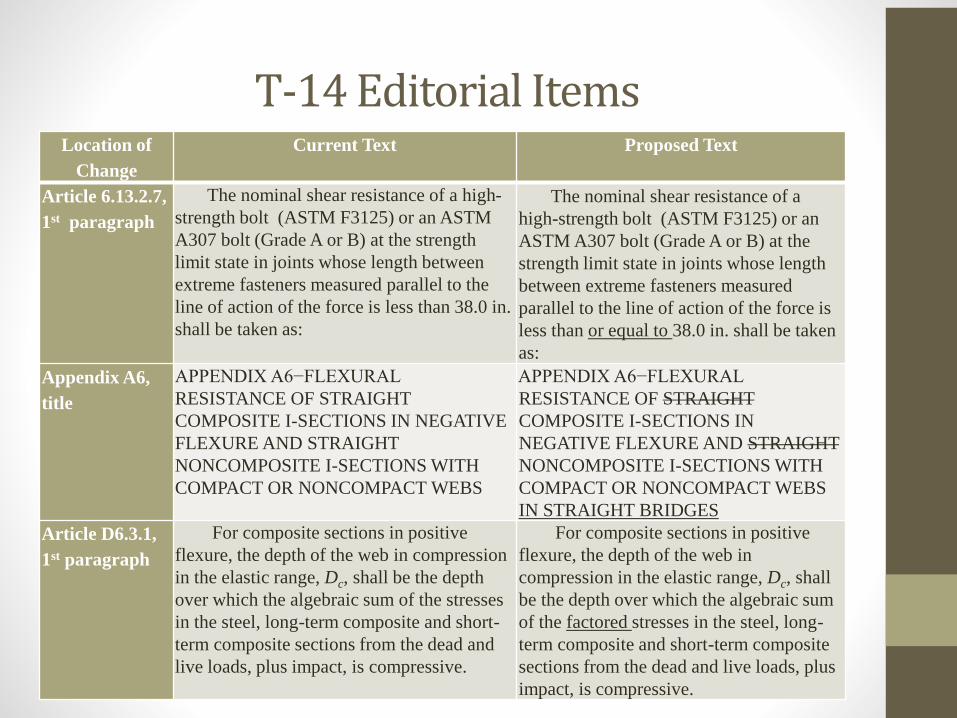
T-14 Editorial ItemsLocation of
Change
Current Text Proposed Text
Article 6.13.2.7,
1st paragraph
The nominal shear resistance of a high-
strength bolt (ASTM F3125) or an ASTM
A307 bolt (Grade A or B) at the strength
limit state in joints whose length between
extreme fasteners measured parallel to the
line of action of the force is less than 38.0 in.
shall be taken as:
The nominal shear resistance of a
high-strength bolt (ASTM F3125) or an
ASTM A307 bolt (Grade A or B) at the
strength limit state in joints whose length
between extreme fasteners measured
parallel to the line of action of the force is
less than or equal to 38.0 in. shall be taken
as:
Appendix A6,
title
APPENDIX A6−FLEXURAL
RESISTANCE OF STRAIGHT
COMPOSITE I-SECTIONS IN NEGATIVE
FLEXURE AND STRAIGHT
NONCOMPOSITE I-SECTIONS WITH
COMPACT OR NONCOMPACT WEBS
APPENDIX A6−FLEXURAL
RESISTANCE OF STRAIGHT
COMPOSITE I-SECTIONS IN
NEGATIVE FLEXURE AND STRAIGHT
NONCOMPOSITE I-SECTIONS WITH
COMPACT OR NONCOMPACT WEBS
IN STRAIGHT BRIDGES
Article D6.3.1,
1st paragraph
For composite sections in positive
flexure, the depth of the web in compression
in the elastic range, Dc, shall be the depth
over which the algebraic sum of the stresses
in the steel, long-term composite and short-
term composite sections from the dead and
live loads, plus impact, is compressive.
For composite sections in positive
flexure, the depth of the web in
compression in the elastic range, Dc, shall
be the depth over which the algebraic sum
of the factored stresses in the steel, long-
term composite and short-term composite
sections from the dead and live loads, plus
impact, is compressive.
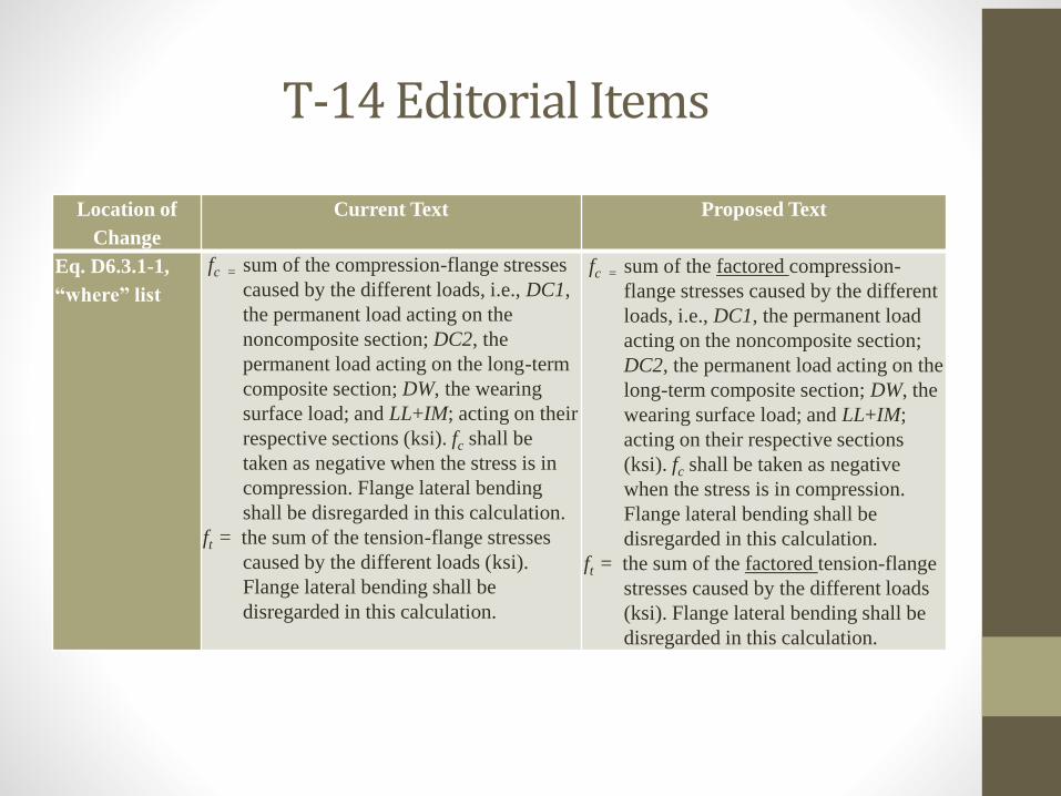
T-14 Editorial Items
Location of
Change
Current Text Proposed Text
Eq. D6.3.1-1,
“where” list
fc = sum of the compression-flange stresses
caused by the different loads, i.e., DC1,
the permanent load acting on the
noncomposite section; DC2, the
permanent load acting on the long-term
composite section; DW, the wearing
surface load; and LL+IM; acting on their
respective sections (ksi). fc shall be
taken as negative when the stress is in
compression. Flange lateral bending
shall be disregarded in this calculation.
ft = the sum of the tension-flange stresses
caused by the different loads (ksi).
Flange lateral bending shall be
disregarded in this calculation.
fc = sum of the factored compression-
flange stresses caused by the different
loads, i.e., DC1, the permanent load
acting on the noncomposite section;
DC2, the permanent load acting on the
long-term composite section; DW, the
wearing surface load; and LL+IM;
acting on their respective sections
(ksi). fc shall be taken as negative
when the stress is in compression.
Flange lateral bending shall be
disregarded in this calculation.
ft = the sum of the factored tension-flange
stresses caused by the different loads
(ksi). Flange lateral bending shall be
disregarded in this calculation.