GRAVITY WALL DESIGN METHODOLOGY STONE …ob8uch-i/files/... · interface angle - δ = ½ φ (see...
21
Page 1 / 12 Project Gravity Wall Design Methodology Project # 08110.00 Date 5/12/09 13478 Chandler Road, Omaha, Nebraska 68138 402/556-2171 (Fax 402/556-7831) GRAVITY WALL DESIGN METHODOLOGY STONE STRONG PRECAST MODULAR BLOCK Evaluate according to industry practice following AASHTO and NCMA analytical techniques – refer to: AASHTO Standard Specifications for Highway Bridges 2002, 17 th Addition NCMA Design Manual for Segmental Retaining Wall, Second Edition Additional analytical methods and theories are taken from other AASHTO versions and other FHWA guidelines – refer to: Mechanically Stabilized Earth Walls and Reinforced Slopes design and Construction Guidelines, NHI-00-043 Properties of Soil/Aggregate soil and material properties should be determined for the specific materials to be used. unit fill - γ a = 110 pcf max, (see AASHTO 2002 5.9.2) & φ u leveling base – aggregate base typical γ b & φ b (or concrete base may be substituted) retained soil - γ & φ by site conditions foundation soil - γ φ & c by site conditions interface angle - δ = ½ φ (see AASHTO 2002 5.9.2) Geometric Properties Effective weight of unit block weight 24 SF unit – 750 lb/ft of wall 6 SF unit – 450 lb/ft of wall weight of aggregate 24 SF unit – 596 lb/ft of wall 6 SF unit – 296 lb/ft of wall Only 80% of the weight of aggregate and soil is included in the overturning calculations, W’ (see AASHTO 2002 5.9.2).
Transcript of GRAVITY WALL DESIGN METHODOLOGY STONE …ob8uch-i/files/... · interface angle - δ = ½ φ (see...
Page 1 / 12 Project
Gravity Wall Design Methodology Project #
08110.00 Date
5/12/09
13478 Chandler Road, Omaha, Nebraska 68138 402/556-2171 (Fax 402/556-7831)
GRAVITY WALL DESIGN METHODOLOGY
STONE STRONG PRECAST MODULAR BLOCK Evaluate according to industry practice following AASHTO and NCMA analytical techniques – refer to: AASHTO Standard Specifications for Highway Bridges 2002, 17th Addition NCMA Design Manual for Segmental Retaining Wall, Second Edition Additional analytical methods and theories are taken from other AASHTO versions and other FHWA guidelines – refer to:
Mechanically Stabilized Earth Walls and Reinforced Slopes design and Construction Guidelines, NHI-00-043
Properties of Soil/Aggregate soil and material properties should be determined for the specific materials to be used.
unit fill - γa = 110 pcf max, (see AASHTO 2002 5.9.2) & φu
leveling base – aggregate base typical γb & φb (or concrete base may be substituted)
retained soil - γ & φ by site conditions
foundation soil - γ φ & c by site conditions
interface angle - δ = ½ φ (see AASHTO 2002 5.9.2) Geometric Properties
Effective weight of unit block weight 24 SF unit – 750 lb/ft of wall 6 SF unit – 450 lb/ft of wall weight of aggregate 24 SF unit – 596 lb/ft of wall 6 SF unit – 296 lb/ft of wall
Only 80% of the weight of aggregate and soil is included in the overturning calculations, W’ (see AASHTO 2002 5.9.2).
Page 2 / 12 Project
Gravity Wall Design Methodology Project #
08110.00 Date
5/12/09
13478 Chandler Road, Omaha, Nebraska 68138 402/556-2171 (Fax 402/556-7831)
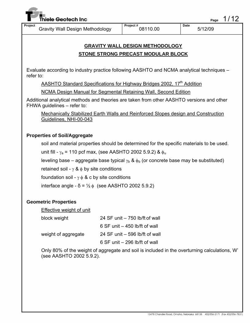
Typical gravity wall configuration:
β
δ−ω
δ−ω
ω
Page 3 / 12 Project
Gravity Wall Design Methodology Project #
08110.00 Date
5/12/09
13478 Chandler Road, Omaha, Nebraska 68138 402/556-2171 (Fax 402/556-7831)
Unit Width/Center of Mass The nominal unit width is 44 inches for both 24 SF and 6 SF blocks. The combined center of mass of the concrete block and the unit fill is at 22.7 inches from the face. These values may be reduced by up to 2 inches to account for the rounding of the face.
wu = 3.50 ft xu = 1.73 ft
Wall batter The wall system is based around the 24 SF block that is 36 inches of height. The next block atop a 24 SF block will batter back 4 inches. The 6 SF block is 18 inches tall, and the next block atop a 6 SF block will batter 2 inches.
4 in. setback per 24 SF block (36 in. tall) 2 in. setback per 6 SF block (18 in. tall)
ω = tan-1(4/36) = 6.34° ω’ = tan-1(4/36) = 6.34° (batter along back face matches the batter along the front)
Base Thickness/Embedment The type and thickness of wall base or leveling pad and depth of embedment can vary by site requirements. A granular base with a thickness of 9 inches is commonly used, but the thickness can be adjusted to reduce the contact pressure. A concrete leveling pad or footing can also be used. The required embedment to the top of the base is related to the exposed height of the wall and by the slope at the toe, as well as other factors. The required embedment can be calculated for slopes steeper than 6H:1V using the following equation:
he = H’/(20*S/6) where S is the run of the toe slope per unit fall and H’ is the exposed height
A minimum embedment of 6 to 9 inches is recommended for private projects. A minimum embedment of 20 inches or more may be required for highway applications.
Page 4 / 12 Project
Gravity Wall Design Methodology Project #
08110.00 Date
5/12/09
13478 Chandler Road, Omaha, Nebraska 68138 402/556-2171 (Fax 402/556-7831)
Tail Extension Adjustments
The gravity wall capability can be increased by using a precast Mass Extender block (limited to approximately 12 additional inches, for a total block width of 56 inches) or a cast-in-place tail extension (width is not limited – recommend height be at least 2 times the width to provide shear through the tail openings). If tail extensions are used, the following adjustments are made:
Wall batter
Wall batter is recalculated along the back of the wall from the rear of the tail extension to the rear of the top of the wall. Use ω’ in Coulomb equation and earth pressure component calculations. To calculate ω’ it is necessary to know the effective setback width, ws, which is the horizontal distance between the back edge of the top block and the back edge of the mass extender at the bottom. ws is the batter of the front face minus the length of tail extension, wte. ws is negative when the mass extender projects further than the back of the top block. Knowing this distance and the height of wall:
ω’ = arctan(ws / Hw)
Interface Angle
δ = ¾ φ (see AASHTO 2002 5.9.2)
Weight of Wall
The weight of the wall includes the contributions of the mass extender and the soil wedge atop the mass extender. A typical concrete unit weight is 145 pcf. Use the soil unit weight for the soil wedge.
Wte = (wte * Hte) * 145 pcf where wte is the width of the tail extension and Hte is the height of the extension (both in ft)
The weight of the soil triangle is calculated using the following equation:
Ws = (H - Hte) * γ * wte/2 Note: The soil wedge is defined by the limit of the tail extension and not by the simplified batter of the back of the wall. The simplified batter is used in the earth pressure analysis. Since the minimum width of the tail extension is typically maintained, it may project beyond the extension at the first course.
Page 5 / 12 Project
Gravity Wall Design Methodology Project #
08110.00 Date
5/12/09
13478 Chandler Road, Omaha, Nebraska 68138 402/556-2171 (Fax 402/556-7831)
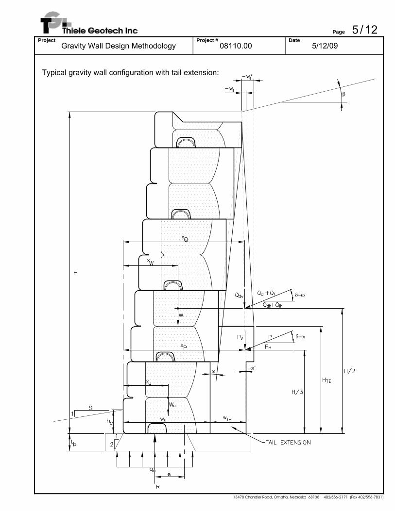
Typical gravity wall configuration with tail extension:
−ω'ω
δ−ω
δ−ω
β
'
Page 6 / 12 Project
Gravity Wall Design Methodology Project #
08110.00 Date
5/12/09
13478 Chandler Road, Omaha, Nebraska 68138 402/556-2171 (Fax 402/556-7831)
Calculate Forces
Coulomb active earth pressure coefficient (see AASHTO 2002 5.5.2-1)
( )
( ) ( ) ( ) ( )( ) ( )
2
2
2
a
β'cos'cossinsin1'cos'cos
'cosK
⎥⎦
⎤⎢⎣
⎡
+ωδ−ωβ−φδ+φ
+δ−ωω
ω+φ=
Earth load components (see AASHTO 2002 5.5.2-1)
Vertical Forces:
Pv = 0.5 KaγH2sin(δ - ω') Qdv = KaQ*H*sin(δ - ω’) where Q is the effective surcharge in psf
Horizontal Forces:
Ph = 0.5 KaγH2cos(δ - ω’) Qdh = KaQ*H*cos(δ - ω’) where Q is the effective surcharge in psf Qlh = KaQ*H*cos(δ - ω’) where Q is the effective surcharge in psf Note: Surcharge loads may be divided into dead and live load components. The vertical component of the live load (Qlv) is a stabilizing force and should be neglected as conservative.
Resisting forces
Vertical Forces: Wb – Weight of wall units Wte – Weight of concrete tail extension, if used Wa – Weight of infill aggregate (use 80% aggregate weight for overturning) Ws – Weight of soil atop tail extension (use 80% weight for overturning)
The center of gravity of the components of the wall can be calculated by laying out the components of the wall and taking a weighted average of their weight and distance from the hinge point of the block (see AASHTO 2002 5.9.2). Alternately, the center of mass can be calculated using the following equations:
Page 7 / 12 Project
Gravity Wall Design Methodology Project #
08110.00 Date
5/12/09
13478 Chandler Road, Omaha, Nebraska 68138 402/556-2171 (Fax 402/556-7831)
The center of mass of the stack of blocks is calculated as: xb = xu + (H - hu)/2 * tan(ω) The center of mass of the soil triangle over the tail is;
xs = wu + (Hte - hu) * tan(ω) + 2 * wte/3 - ws’/3 The center of mass of the tail extension can be calculated with the following equation:
xte = wu + wte/2 This leads to an overall adjusted center of mass of:
xw = [[xu + (H - hu)/2 * tan(ω)] * (Wb + Wa) + xte * Wte + xs * Ws]/(Wb + Wa + Wte + Ws) Note: the height of unit, hu, is taken as 3 ft. based on the 24 SF unit instead of 1.5 ft. based on the 6 SF unit to produce the more conservative result (units can be stacked with either unit as the bottom course).
The resultants of the earth load components are calculated as follows:
xPv=(H/3)*tan(ω’) + wu + wte
xQdv=(H/2) )*tan(ω’) + wu + wte xPh=H/3 xQdh=H/2 xQlh=H/2
Table of Forces & Moments
Force x Moment about toe (lb) (ft) (lb*ft)
Vertical Forces weight of wall Wb + Wa + Wte + Ws xw (Wb + Wa + Wte + Ws) * xw
modified weight Wb + 0.8*Wa + Wte + 0.8*Ws xw (Wb + 0.8*Wa + Wte + 0.8*Ws) * xw
earth pressure Pv xPv Pv*xPv
DL surcharge Qdv xQdv Qdv*xQdv
Horizontal Forces earth pressure Ph xPh Ph*xPh
DL surcharge Qdh xQdh Qdh*xQdh LL surcharge Qlh xQlh Qlh*xQlh
Page 8 / 12 Project
Gravity Wall Design Methodology Project #
08110.00 Date
5/12/09
13478 Chandler Road, Omaha, Nebraska 68138 402/556-2171 (Fax 402/556-7831)
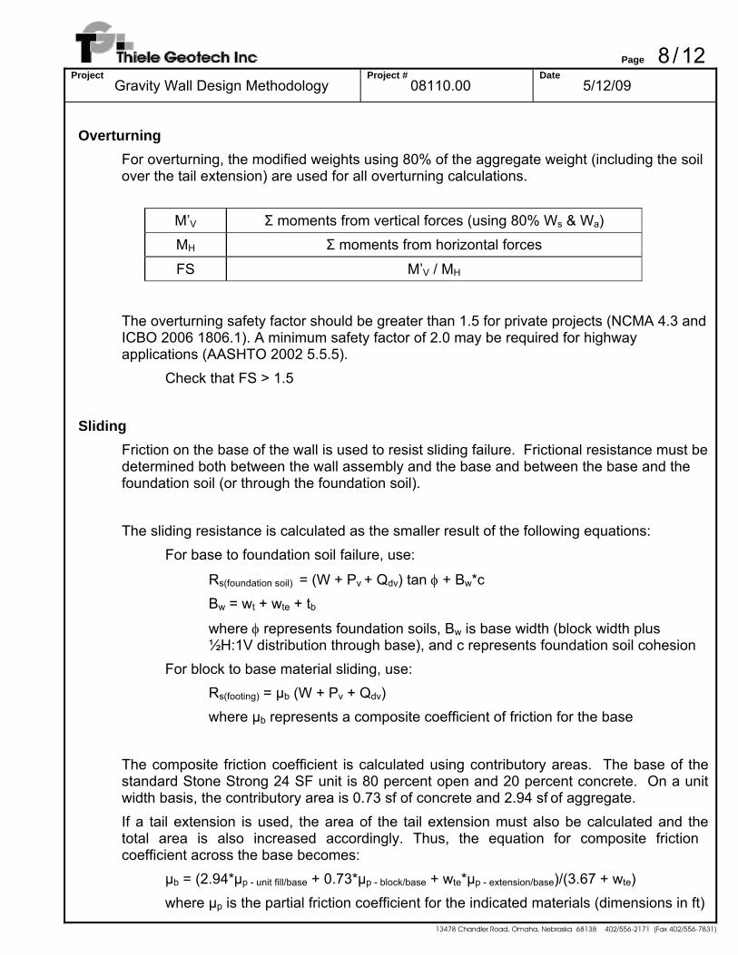
Overturning
For overturning, the modified weights using 80% of the aggregate weight (including the soil over the tail extension) are used for all overturning calculations.
M’V Σ moments from vertical forces (using 80% Ws & Wa)
MH Σ moments from horizontal forces
FS M’V / MH
The overturning safety factor should be greater than 1.5 for private projects (NCMA 4.3 and ICBO 2006 1806.1). A minimum safety factor of 2.0 may be required for highway applications (AASHTO 2002 5.5.5).
Check that FS > 1.5 Sliding
Friction on the base of the wall is used to resist sliding failure. Frictional resistance must be determined both between the wall assembly and the base and between the base and the foundation soil (or through the foundation soil). The sliding resistance is calculated as the smaller result of the following equations:
For base to foundation soil failure, use:
Rs(foundation soil) = (W + Pv + Qdv) tan φ + Bw*c Bw = wt + wte + tb
where φ represents foundation soils, Bw is base width (block width plus ½H:1V distribution through base), and c represents foundation soil cohesion
For block to base material sliding, use: Rs(footing) = μb (W + Pv + Qdv) where μb represents a composite coefficient of friction for the base
The composite friction coefficient is calculated using contributory areas. The base of the standard Stone Strong 24 SF unit is 80 percent open and 20 percent concrete. On a unit width basis, the contributory area is 0.73 sf of concrete and 2.94 sf of aggregate. If a tail extension is used, the area of the tail extension must also be calculated and the total area is also increased accordingly. Thus, the equation for composite friction coefficient across the base becomes: μb = (2.94*μp - unit fill/base + 0.73*μp - block/base + wte*μp - extension/base)/(3.67 + wte) where μp is the partial friction coefficient for the indicated materials (dimensions in ft)
Page 9 / 12 Project
Gravity Wall Design Methodology Project #
08110.00 Date
5/12/09
13478 Chandler Road, Omaha, Nebraska 68138 402/556-2171 (Fax 402/556-7831)
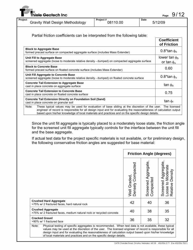
Partial friction coefficients can be interpreted from the following table:
Coefficient of Friction
Block to Aggregate Base formed precast surface on compacted aggregate surface (includes Mass Extender) 0.8*tan φb
Unit Fill to Aggregate Base screened aggregate (loose to moderate relative density - dumped) on compacted aggregate surface
lower tan φb or tan φu
Block to Concrete Base formed precast surface on floated concrete surface (includes Mass Extender) 0.60 Unit Fill Aggregate to Concrete Base screened aggregate (loose to moderate relative density - dumped) on floated concrete surface 0.8*tan φu Concrete Tail Extension to Aggregate Base cast in place concrete on aggregate surface tan φb Concrete Tail Extension to Concrete Base cast in place concrete on floated concrete surface 0.75 Concrete Tail Extension Directly on Foundation Soil (Sand) cast in place concrete on granular soil tan φf Note: These typical values may be used for evaluation of base sliding at the discretion of the user. The licensed
engineer of record is responsible for all design input and for evaluating the reasonableness of calculation output based upon his/her knowledge of local materials and practices and on the specific design details.
Since the unit fill aggregate is typically placed to a moderately loose state, the friction angle for the screened unit fill aggregate typically controls for the interface between the unit fill and the base aggregate. If actual test data for the project specific materials is not available, or for preliminary design, the following conservative friction angles are suggested for base material: Friction Angle (degrees)
Wel
l Gra
ded,
Den
sely
Com
pact
ed
Scr
eene
d A
ggre
gate
,
Com
pact
ed
Scr
eene
d A
ggre
gate
,
Loos
e to
Mod
erat
e R
elat
ive
Den
sity
Crushed Hard Aggregate >75% w/ 2 fractured faces, hard natural rock 42 40 36
Crushed Aggregate >75% w/ 2 fractured faces, medium natural rock or recycled concrete 40 38 35
Cracked Gravel >90% w/ 1 fractured face 36 35 32 Note: Physical testing of specific aggregates is recommended. When test data is not available, these typical
values may be used at the discretion of the user. The licensed engineer of record is responsible for all design input and for evaluating the reasonableness of calculation output based upon his/her knowledge of local materials and practices and on the specific design details.
Page 10 / 12 Project
Gravity Wall Design Methodology Project #
08110.00 Date
5/12/09
13478 Chandler Road, Omaha, Nebraska 68138 402/556-2171 (Fax 402/556-7831)
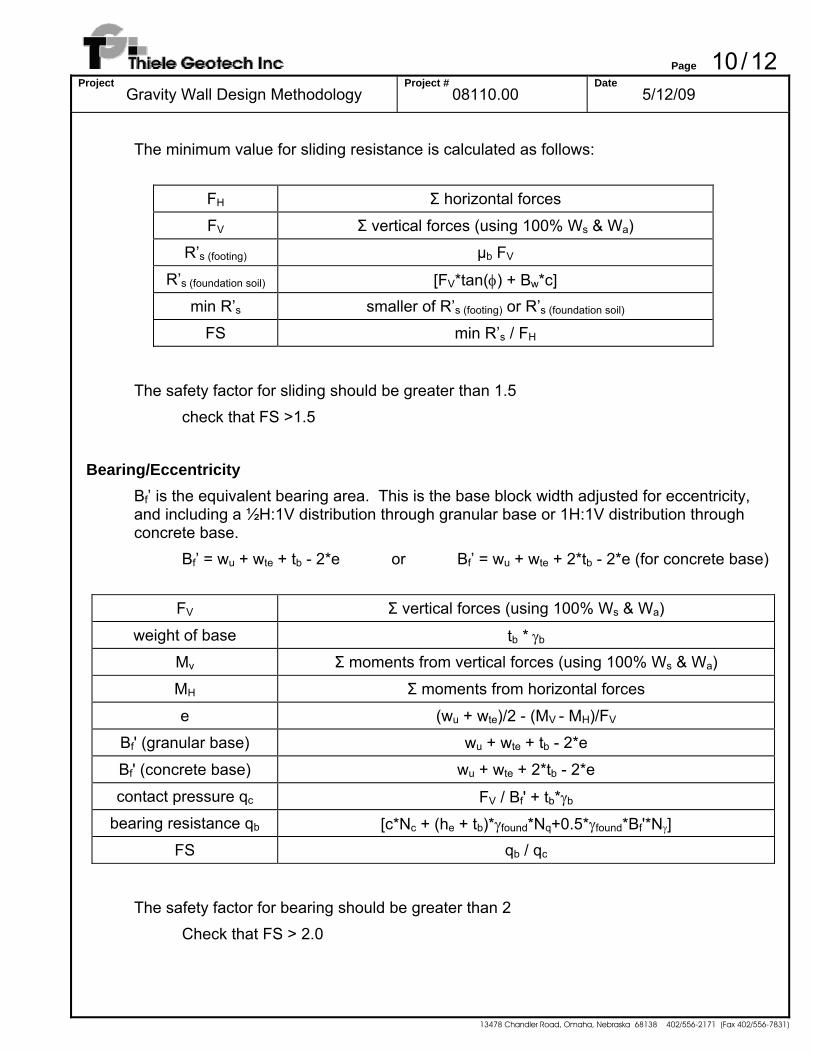
The minimum value for sliding resistance is calculated as follows:
FH Σ horizontal forces
FV Σ vertical forces (using 100% Ws & Wa)
R’s (footing) μb FV
R’s (foundation soil) [FV*tan(φ) + Bw*c] min R’s smaller of R’s (footing) or R’s (foundation soil)
FS min R’s / FH
The safety factor for sliding should be greater than 1.5
check that FS >1.5 Bearing/Eccentricity
Bf’ is the equivalent bearing area. This is the base block width adjusted for eccentricity, and including a ½H:1V distribution through granular base or 1H:1V distribution through concrete base.
Bf’ = wu + wte + tb - 2*e or Bf’ = wu + wte + 2*tb - 2*e (for concrete base)
FV Σ vertical forces (using 100% Ws & Wa)
weight of base tb * γb Mv Σ moments from vertical forces (using 100% Ws & Wa)
MH Σ moments from horizontal forces
e (wu + wte)/2 - (MV - MH)/FV
Bf' (granular base) wu + wte + tb - 2*e
Bf' (concrete base) wu + wte + 2*tb - 2*e
contact pressure qc FV / Bf' + tb*γb bearing resistance qb [c*Nc + (he + tb)*γfound*Nq+0.5*γfound*Bf'*Nγ]
FS qb / qc
The safety factor for bearing should be greater than 2
Check that FS > 2.0
Page 11 / 12 Project
Gravity Wall Design Methodology Project #
08110.00 Date
5/12/09
13478 Chandler Road, Omaha, Nebraska 68138 402/556-2171 (Fax 402/556-7831)
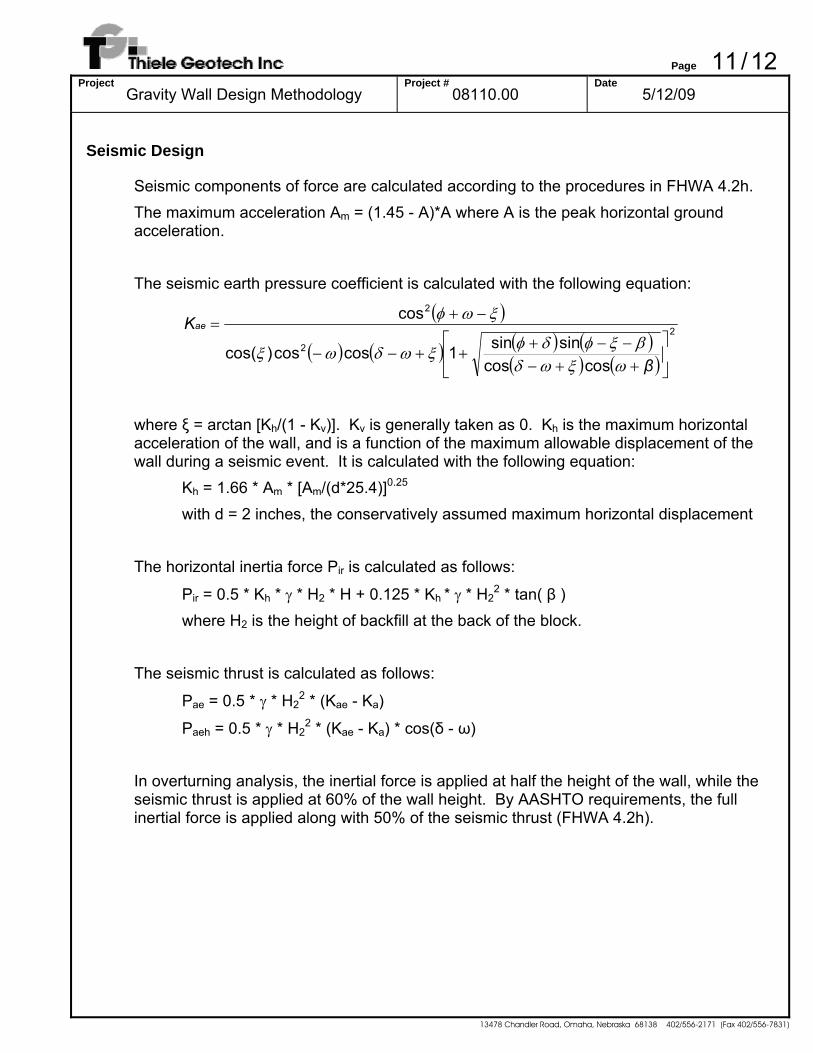
Seismic Design
Seismic components of force are calculated according to the procedures in FHWA 4.2h. The maximum acceleration Am = (1.45 - A)*A where A is the peak horizontal ground acceleration. The seismic earth pressure coefficient is calculated with the following equation:
( )
( ) ( ) ( ) ( )( ) ( )
2
2
2
coscossinsin1coscos)cos(
cos
⎥⎦
⎤⎢⎣
⎡
++−−−+
++−−
−+=
β
Kae
ωξωδβξφδφξωδωξ
ξωφ
where ξ = arctan [Kh/(1 - Kv)]. Kv is generally taken as 0. Kh is the maximum horizontal
acceleration of the wall, and is a function of the maximum allowable displacement of the wall during a seismic event. It is calculated with the following equation:
Kh = 1.66 * Am * [Am/(d*25.4)]0.25 with d = 2 inches, the conservatively assumed maximum horizontal displacement
The horizontal inertia force Pir is calculated as follows:
Pir = 0.5 * Kh * γ * H2 * H + 0.125 * Kh * γ * H22 * tan( β )
where H2 is the height of backfill at the back of the block.
The seismic thrust is calculated as follows:
Pae = 0.5 * γ * H22 * (Kae - Ka)
Paeh = 0.5 * γ * H22 * (Kae - Ka) * cos(δ - ω)
In overturning analysis, the inertial force is applied at half the height of the wall, while the seismic thrust is applied at 60% of the wall height. By AASHTO requirements, the full inertial force is applied along with 50% of the seismic thrust (FHWA 4.2h).
Page 12 / 12 Project
Gravity Wall Design Methodology Project #
08110.00 Date
5/12/09
13478 Chandler Road, Omaha, Nebraska 68138 402/556-2171 (Fax 402/556-7831)
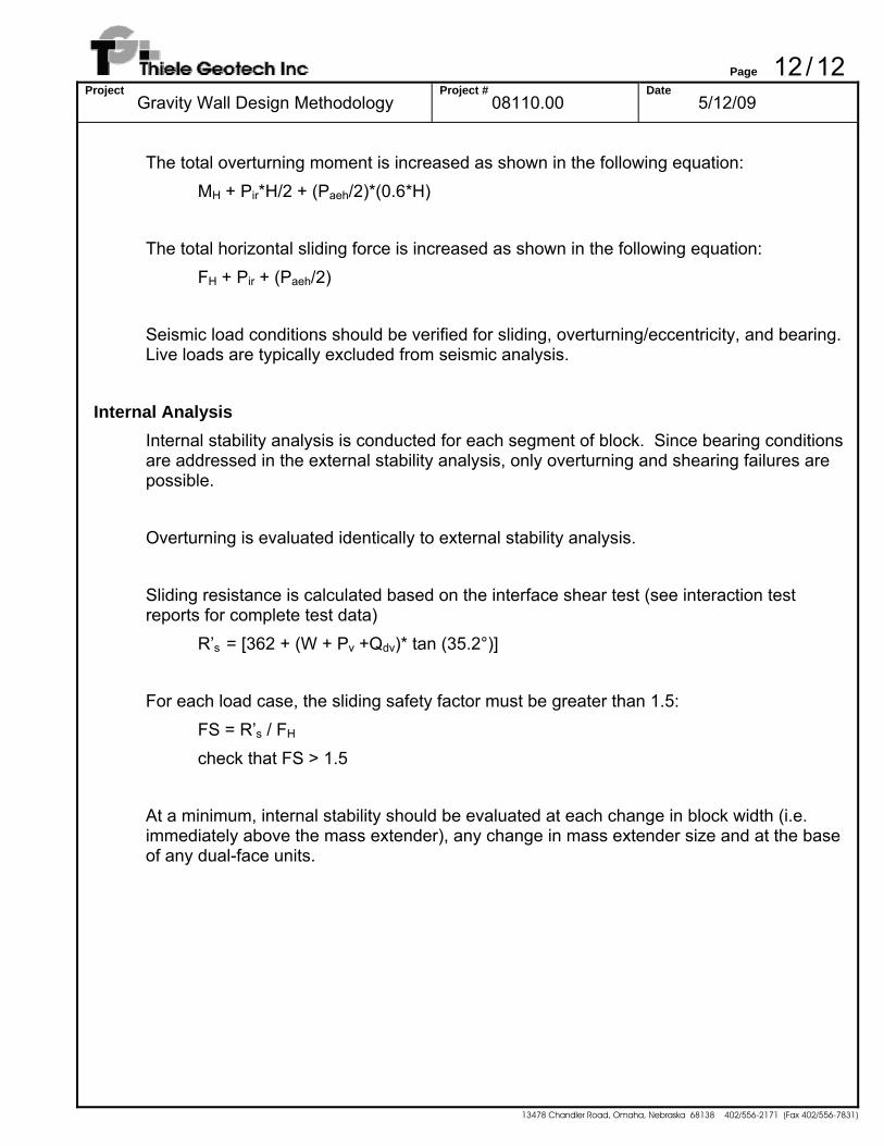
The total overturning moment is increased as shown in the following equation:
MH + Pir*H/2 + (Paeh/2)*(0.6*H) The total horizontal sliding force is increased as shown in the following equation:
FH + Pir + (Paeh/2) Seismic load conditions should be verified for sliding, overturning/eccentricity, and bearing. Live loads are typically excluded from seismic analysis.
Internal Analysis Internal stability analysis is conducted for each segment of block. Since bearing conditions are addressed in the external stability analysis, only overturning and shearing failures are possible. Overturning is evaluated identically to external stability analysis. Sliding resistance is calculated based on the interface shear test (see interaction test reports for complete test data)
R’s = [362 + (W + Pv +Qdv)* tan (35.2°)] For each load case, the sliding safety factor must be greater than 1.5: FS = R’s / FH
check that FS > 1.5 At a minimum, internal stability should be evaluated at each change in block width (i.e. immediately above the mass extender), any change in mass extender size and at the base of any dual-face units.

Page 1/4Project
Example Gravity Calculation Project #
08110.00 Date
6/28/09
13478 Chandler Road, Omaha, Nebraska 68138 402/556-2171 (Fax 402/556-7831)
Note: Examples to demonstrate method of analysis only - not intended to conform w/ AASHTO safety factors
Example section – 9 ft tall unreinforced wall, 4H:1V backslope, sand backfill Uniform soil (sand) - γ = 125 pcf φ = 30° c = 0 psf Wall is composed of three 24 SF blocks ω’ = arctan((3*4”)/(9ft*12”/ft)) = 6.34° δ = ½*30° = 15°
Granular base aggregate – φ = 40°
Unit fill aggregate – φ = 35° Weight of Wall Wb = (3*6,000 lb)/8 ft = 2,250 lb/ft block Wa = (3*43.32 ft3*110 pcf)/8 ft = 1,787 lb/ft aggregate fill Total Wall Weight = 2,250 + 1,787 = 4,037 lb/ft W’ = 1,787 lb/ft*0.80 + 2,250 lb/ft = 3,680 lb/ft
Forces/Geometric Properties Center of Gravity xblock – 22.7” from face, with 2 additional inches removed due to rounding – 1.73’ total xw = [(1.73+0.5*(9 ft-3 ft)*tan(6.34°))*(2,250 lb + 1,787 lb) ]/4,037 lb = 2.06 ft wu = (44 in-2 in)/12 = 3.5 ft Soil force components
( )
( ) ( ) ( ) ( )( ) ( )
2
2
2
a
0.1434.6cos 1534.6 cos0.1430sin 1530sin11534.6cos 34.6cos
6.3430cosK
⎥⎦
⎤⎢⎣
⎡
°+°°−°°−°°+°
+°−°°
°+°= = 0.313
Ph = 0.5*(0.313)*125pcf*(9 ft)2*cos(15° - 6.34°) = 1,564 lb/ft Pv = 0.5*(0.313)*125pcf*(9 ft)2*sin(15° - 6.34°) = 238 lb/ft
Page 2/4Project
Example Gravity Calculation Project #
08110.00 Date
6/28/09
13478 Chandler Road, Omaha, Nebraska 68138 402/556-2171 (Fax 402/556-7831)
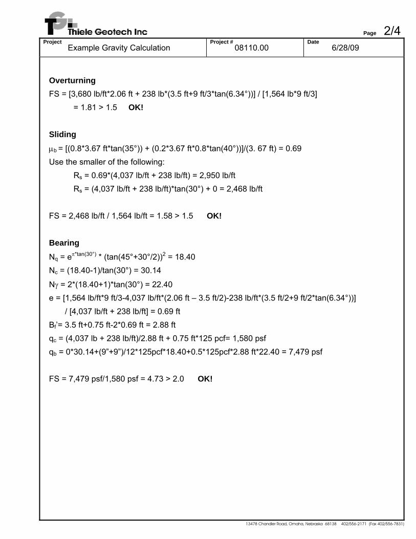
Overturning FS = [3,680 lb/ft*2.06 ft + 238 lb*(3.5 ft+9 ft/3*tan(6.34°))] / [1,564 lb*9 ft/3] = 1.81 > 1.5 OK! Sliding μb = [(0.8*3.67 ft*tan(35°)) + (0.2*3.67 ft*0.8*tan(40°))]/(3. 67 ft) = 0.69 Use the smaller of the following:
Rs = 0.69*(4,037 lb/ft + 238 lb/ft) = 2,950 lb/ft Rs = (4,037 lb/ft + 238 lb/ft)*tan(30°) + 0 = 2,468 lb/ft
FS = 2,468 lb/ft / 1,564 lb/ft = 1.58 > 1.5 OK! Bearing Nq = eπ*tan(30°) * (tan(45°+30°/2))2 = 18.40 Nc = (18.40-1)/tan(30°) = 30.14
Nγ = 2*(18.40+1)*tan(30°) = 22.40 e = [1,564 lb/ft*9 ft/3-4,037 lb/ft*(2.06 ft – 3.5 ft/2)-238 lb/ft*(3.5 ft/2+9 ft/2*tan(6.34°))] / [4,037 lb/ft + 238 lb/ft] = 0.69 ft Bf’= 3.5 ft+0.75 ft-2*0.69 ft = 2.88 ft qc = (4,037 lb + 238 lb/ft)/2.88 ft + 0.75 ft*125 pcf= 1,580 psf qb = 0*30.14+(9”+9”)/12*125pcf*18.40+0.5*125pcf*2.88 ft*22.40 = 7,479 psf FS = 7,479 psf/1,580 psf = 4.73 > 2.0 OK!
Page 3/4Project
Example Gravity Calculation Project #
08110.00 Date
6/28/09
13478 Chandler Road, Omaha, Nebraska 68138 402/556-2171 (Fax 402/556-7831)
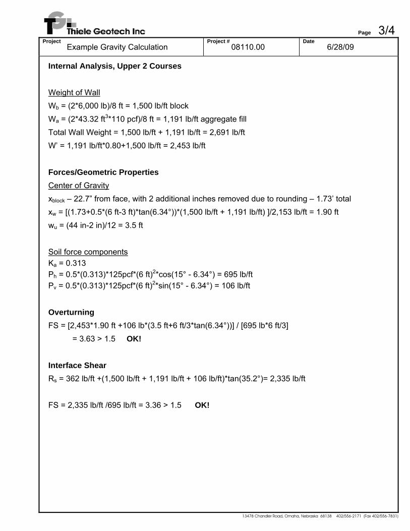
Internal Analysis, Upper 2 Courses Weight of Wall Wb = (2*6,000 lb)/8 ft = 1,500 lb/ft block Wa = (2*43.32 ft3*110 pcf)/8 ft = 1,191 lb/ft aggregate fill Total Wall Weight = 1,500 lb/ft + 1,191 lb/ft = 2,691 lb/ft W’ = 1,191 lb/ft*0.80+1,500 lb/ft = 2,453 lb/ft Forces/Geometric Properties Center of Gravity xblock – 22.7” from face, with 2 additional inches removed due to rounding – 1.73’ total xw = [(1.73+0.5*(6 ft-3 ft)*tan(6.34°))*(1,500 lb/ft + 1,191 lb/ft) ]/2,153 lb/ft = 1.90 ft wu = (44 in-2 in)/12 = 3.5 ft Soil force components Ka = 0.313 Ph = 0.5*(0.313)*125pcf*(6 ft)2*cos(15° - 6.34°) = 695 lb/ft Pv = 0.5*(0.313)*125pcf*(6 ft)2*sin(15° - 6.34°) = 106 lb/ft Overturning FS = [2,453*1.90 ft +106 lb*(3.5 ft+6 ft/3*tan(6.34°))] / [695 lb*6 ft/3] = 3.63 > 1.5 OK! Interface Shear Rs = 362 lb/ft +(1,500 lb/ft + 1,191 lb/ft + 106 lb/ft)*tan(35.2°)= 2,335 lb/ft FS = 2,335 lb/ft /695 lb/ft = 3.36 > 1.5 OK!
Page 4/4Project
Example Gravity Calculation Project #
08110.00 Date
6/28/09
13478 Chandler Road, Omaha, Nebraska 68138 402/556-2171 (Fax 402/556-7831)
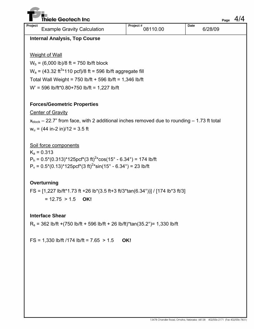
Internal Analysis, Top Course Weight of Wall Wb = (6,000 lb)/8 ft = 750 lb/ft block Wa = (43.32 ft3*110 pcf)/8 ft = 596 lb/ft aggregate fill Total Wall Weight = 750 lb/ft + 596 lb/ft = 1,346 lb/ft W’ = 596 lb/ft*0.80+750 lb/ft = 1,227 lb/ft Forces/Geometric Properties Center of Gravity xblock – 22.7” from face, with 2 additional inches removed due to rounding – 1.73 ft total wu = (44 in-2 in)/12 = 3.5 ft Soil force components Ka = 0.313 Ph = 0.5*(0.313)*125pcf*(3 ft)2*cos(15° - 6.34°) = 174 lb/ft Pv = 0.5*(0.13)*125pcf*(3 ft)2*sin(15° - 6.34°) = 23 lb/ft Overturning FS = [1,227 lb/ft*1.73 ft +26 lb*(3.5 ft+3 ft/3*tan(6.34°))] / [174 lb*3 ft/3] = 12.75 > 1.5 OK! Interface Shear Rs = 362 lb/ft +(750 lb/ft + 596 lb/ft + 26 lb/ft)*tan(35.2°)= 1,330 lb/ft FS = 1,330 lb/ft /174 lb/ft = 7.65 > 1.5 OK!
Page 1/5Project
Example Gravity Calculation Project #
08110.00 Date
6/28/09
13478 Chandler Road, Omaha, Nebraska 68138 402/556-2171 (Fax 402/556-7831)
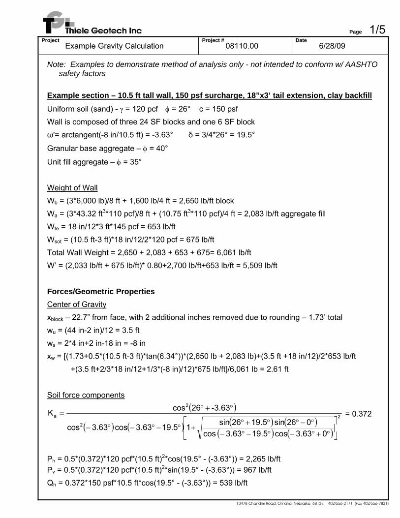
Note: Examples to demonstrate method of analysis only - not intended to conform w/ AASHTO safety factors
Example section – 10.5 ft tall wall, 150 psf surcharge, 18”x3’ tail extension, clay backfill Uniform soil (sand) - γ = 120 pcf φ = 26° c = 150 psf Wall is composed of three 24 SF blocks and one 6 SF block ω'= arctangent(-8 in/10.5 ft) = -3.63° δ = 3/4*26° = 19.5°
Granular base aggregate – φ = 40°
Unit fill aggregate – φ = 35° Weight of Wall Wb = (3*6,000 lb)/8 ft + 1,600 lb/4 ft = 2,650 lb/ft block Wa = (3*43.32 ft3*110 pcf)/8 ft + (10.75 ft3*110 pcf)/4 ft = 2,083 lb/ft aggregate fill Wte = 18 in/12*3 ft*145 pcf = 653 lb/ft Wsot = (10.5 ft-3 ft)*18 in/12/2*120 pcf = 675 lb/ft Total Wall Weight = 2,650 + 2,083 + 653 + 675= 6,061 lb/ft W’ = (2,033 lb/ft + 675 lb/ft)* 0.80+2,700 lb/ft+653 lb/ft = 5,509 lb/ft Forces/Geometric Properties Center of Gravity xblock – 22.7” from face, with 2 additional inches removed due to rounding – 1.73’ total wu = (44 in-2 in)/12 = 3.5 ft ws = 2*4 in+2 in-18 in = -8 in xw = [(1.73+0.5*(10.5 ft-3 ft)*tan(6.34°))*(2,650 lb + 2,083 lb)+(3.5 ft +18 in/12)/2*653 lb/ft
+(3.5 ft+2/3*18 in/12+1/3*(-8 in)/12)*675 lb/ft]/6,061 lb = 2.61 ft Soil force components
( )
( ) ( ) ( ) ( )( ) ( )
2
2
2
a
063.3cos 19.563.3 cos026sin 5.9126sin15.9163.3cos 63.3cos
63.3-26cosK
⎥⎦
⎤⎢⎣
⎡
°+°−°−°−°−°°+°
+°−°−°−
°+°= = 0.372
Ph = 0.5*(0.372)*120 pcf*(10.5 ft)2*cos(19.5° - (-3.63°)) = 2,265 lb/ft Pv = 0.5*(0.372)*120 pcf*(10.5 ft)2*sin(19.5° - (-3.63°)) = 967 lb/ft Qh = 0.372*150 psf*10.5 ft*cos(19.5° - (-3.63°)) = 539 lb/ft
Page 2/5Project
Example Gravity Calculation Project #
08110.00 Date
6/28/09
13478 Chandler Road, Omaha, Nebraska 68138 402/556-2171 (Fax 402/556-7831)
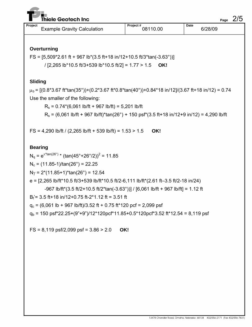
Overturning FS = [5,509*2.61 ft + 967 lb*(3.5 ft+18 in/12+10.5 ft/3*tan(-3.63°))]
/ [2,265 lb*10.5 ft/3+539 lb*10.5 ft/2] = 1.77 > 1.5 OK! Sliding μb = [(0.8*3.67 ft*tan(35°))+(0.2*3.67 ft*0.8*tan(40°))+0.84*18 in/12]/(3.67 ft+18 in/12) = 0.74 Use the smaller of the following:
Rs = 0.74*(6,061 lb/ft + 967 lb/ft) = 5,201 lb/ft Rs = (6,061 lb/ft + 967 lb/ft)*tan(26°) + 150 psf*(3.5 ft+18 in/12+9 in/12) = 4,290 lb/ft
FS = 4,290 lb/ft / (2,265 lb/ft + 539 lb/ft) = 1.53 > 1.5 OK! Bearing Nq = eπ*tan(26°) * (tan(45°+26°/2))2 = 11.85 Nc = (11.85-1)/tan(26°) = 22.25
Nγ = 2*(11.85+1)*tan(26°) = 12.54 e = [2,265 lb/ft*10.5 ft/3+539 lb/ft*10.5 ft/2-6,111 lb/ft*(2.61 ft–3.5 ft/2-18 in/24)
-967 lb/ft*(3.5 ft/2+10.5 ft/2*tan(-3.63°))] / [6,061 lb/ft + 967 lb/ft] = 1.12 ft Bf’= 3.5 ft+18 in/12+0.75 ft-2*1.12 ft = 3.51 ft qc = (6,061 lb + 967 lb/ft)/3.52 ft + 0.75 ft*120 pcf = 2,099 psf qb = 150 psf*22.25+(9”+9”)/12*120pcf*11.85+0.5*120pcf*3.52 ft*12.54 = 8,119 psf FS = 8,119 psf/2,099 psf = 3.86 > 2.0 OK!
Page 3/5Project
Example Gravity Calculation Project #
08110.00 Date
6/28/09
13478 Chandler Road, Omaha, Nebraska 68138 402/556-2171 (Fax 402/556-7831)
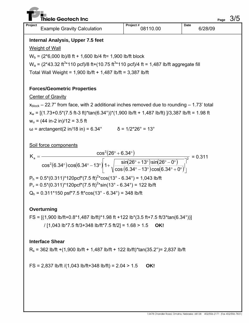
Internal Analysis, Upper 7.5 feet Weight of Wall Wb = (2*6,000 lb)/8 ft + 1,600 lb/4 ft= 1,900 lb/ft block Wa = (2*43.32 ft3*110 pcf)/8 ft+(10.75 ft3*110 pcf)/4 ft = 1,487 lb/ft aggregate fill Total Wall Weight = 1,900 lb/ft + 1,487 lb/ft = 3,387 lb/ft Forces/Geometric Properties Center of Gravity xblock – 22.7” from face, with 2 additional inches removed due to rounding – 1.73’ total xw = [(1.73+0.5*(7.5 ft-3 ft)*tan(6.34°))*(1,900 lb/ft + 1,487 lb/ft) ]/3,387 lb/ft = 1.98 ft wu = (44 in-2 in)/12 = 3.5 ft ω = arctangent(2 in/18 in) = 6.34° δ = 1/2*26° = 13° Soil force components
( )
( ) ( ) ( ) ( )( ) ( )
2
2
2
a
034.6cos 1334.6 cos026sin 3126sin13134.6cos 34.6cos
34.626cosK
⎥⎦
⎤⎢⎣
⎡
°+°°−°°−°°+°
+°−°°
°+°= = 0.311
Ph = 0.5*(0.311)*120pcf*(7.5 ft)2*cos(13° - 6.34°) = 1,043 lb/ft Pv = 0.5*(0.311)*120pcf*(7.5 ft)2*sin(13° - 6.34°) = 122 lb/ft Qh = 0.311*150 psf*7.5 ft*cos(13° - 6.34°) = 348 lb/ft Overturning FS = [(1,900 lb/ft+0.8*1,487 lb/ft)*1.98 ft +122 lb*(3.5 ft+7.5 ft/3*tan(6.34°))]
/ [1,043 lb*7.5 ft/3+348 lb/ft*7.5 ft/2] = 1.68 > 1.5 OK! Interface Shear Rs = 362 lb/ft +(1,900 lb/ft + 1,487 lb/ft + 122 lb/ft)*tan(35.2°)= 2,837 lb/ft FS = 2,837 lb/ft /(1,043 lb/ft+348 lb/ft) = 2.04 > 1.5 OK!
Page 4/5Project
Example Gravity Calculation Project #
08110.00 Date
6/28/09
13478 Chandler Road, Omaha, Nebraska 68138 402/556-2171 (Fax 402/556-7831)
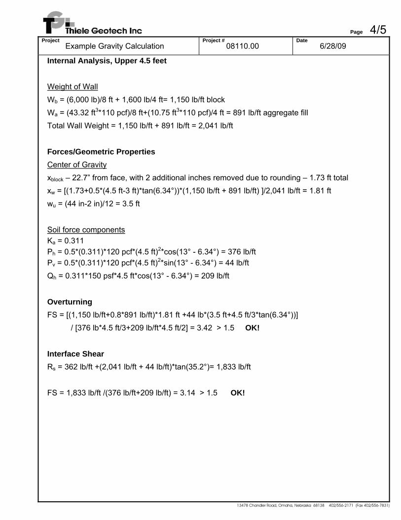
Internal Analysis, Upper 4.5 feet Weight of Wall Wb = (6,000 lb)/8 ft + 1,600 lb/4 ft= 1,150 lb/ft block Wa = (43.32 ft3*110 pcf)/8 ft+(10.75 ft3*110 pcf)/4 ft = 891 lb/ft aggregate fill Total Wall Weight = 1,150 lb/ft + 891 lb/ft = 2,041 lb/ft Forces/Geometric Properties Center of Gravity xblock – 22.7” from face, with 2 additional inches removed due to rounding – 1.73 ft total xw = [(1.73+0.5*(4.5 ft-3 ft)*tan(6.34°))*(1,150 lb/ft + 891 lb/ft) ]/2,041 lb/ft = 1.81 ft wu = (44 in-2 in)/12 = 3.5 ft Soil force components Ka = 0.311 Ph = 0.5*(0.311)*120 pcf*(4.5 ft)2*cos(13° - 6.34°) = 376 lb/ft Pv = 0.5*(0.311)*120 pcf*(4.5 ft)2*sin(13° - 6.34°) = 44 lb/ft Qh = 0.311*150 psf*4.5 ft*cos(13° - 6.34°) = 209 lb/ft Overturning FS = [(1,150 lb/ft+0.8*891 lb/ft)*1.81 ft +44 lb*(3.5 ft+4.5 ft/3*tan(6.34°))]
/ [376 lb*4.5 ft/3+209 lb/ft*4.5 ft/2] = 3.42 > 1.5 OK! Interface Shear Rs = 362 lb/ft +(2,041 lb/ft + 44 lb/ft)*tan(35.2°)= 1,833 lb/ft FS = 1,833 lb/ft /(376 lb/ft+209 lb/ft) = 3.14 > 1.5 OK!
Page 5/5Project
Example Gravity Calculation Project #
08110.00 Date
6/28/09
13478 Chandler Road, Omaha, Nebraska 68138 402/556-2171 (Fax 402/556-7831)
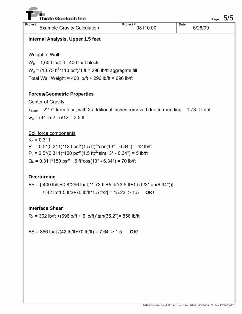
Internal Analysis, Upper 1.5 feet Weight of Wall Wb = 1,600 lb/4 ft= 400 lb/ft block Wa = (10.75 ft3*110 pcf)/4 ft = 296 lb/ft aggregate fill Total Wall Weight = 400 lb/ft + 296 lb/ft = 696 lb/ft Forces/Geometric Properties Center of Gravity xblock – 22.7” from face, with 2 additional inches removed due to rounding – 1.73 ft total wu = (44 in-2 in)/12 = 3.5 ft Soil force components Ka = 0.311 Ph = 0.5*(0.311)*120 pcf*(1.5 ft)2*cos(13° - 6.34°) = 42 lb/ft Pv = 0.5*(0.311)*120 pcf*(1.5 ft)2*sin(13° - 6.34°) = 5 lb/ft Qh = 0.311*150 psf*1.5 ft*cos(13° - 6.34°) = 70 lb/ft Overturning FS = [(400 lb/ft+0.8*296 lb/ft)*1.73 ft +5 lb*(3.5 ft+1.5 ft/3*tan(6.34°))]
/ [42 lb*1.5 ft/3+70 lb/ft*1.5 ft/2] = 15.23 > 1.5 OK! Interface Shear Rs = 362 lb/ft +(696lb/ft + 5 lb/ft)*tan(35.2°)= 856 lb/ft FS = 856 lb/ft /(42 lb/ft+70 lb/ft) = 7.64 > 1.5 OK!


![ON THE ZEROES OF HALF-INTEGRAL WEIGHT EISENSTEIN …...the zeroes of integral weight modular forms, including [5] and [7]. On the other hand, there have been studies of half integral](https://static.fdocument.org/doc/165x107/5f1055f47e708231d4489a78/on-the-zeroes-of-half-integral-weight-eisenstein-the-zeroes-of-integral-weight.jpg)


![[gre] ΜΕΘΟΔΟΛΟΓΙΑ ΤΟΥ ΙΣΟΖΥΓΙΟΥ …aei.pitt.edu/69910/1/methodology-greece.pdfτης που περιέχουν στοιχεία για το επισκο-πούμενο](https://static.fdocument.org/doc/165x107/5f0dcf5d7e708231d43c3296/gre-oe-aeipittedu699101methodology-.jpg)