A Review of the IDEMA PMR Symposium Held on … Review of the IDEMA PMR Symposium Held on December 7...
53
A Review of the IDEMA PMR Symposium Held on December 7, 2006 Presented by Michael A. Russak, Ph.D. Executive Director, IDEMA USA DISKCON Asia Pacific 2007 March 7, 2007 [email protected]
-
Upload
vuongthuan -
Category
Documents
-
view
215 -
download
0
Transcript of A Review of the IDEMA PMR Symposium Held on … Review of the IDEMA PMR Symposium Held on December 7...
A Review of the IDEMA PMR Symposium Held on December 7, 2006
Presented by Michael A. Russak, Ph.D.Executive Director, IDEMA USADISKCON Asia Pacific 2007March 7, [email protected]
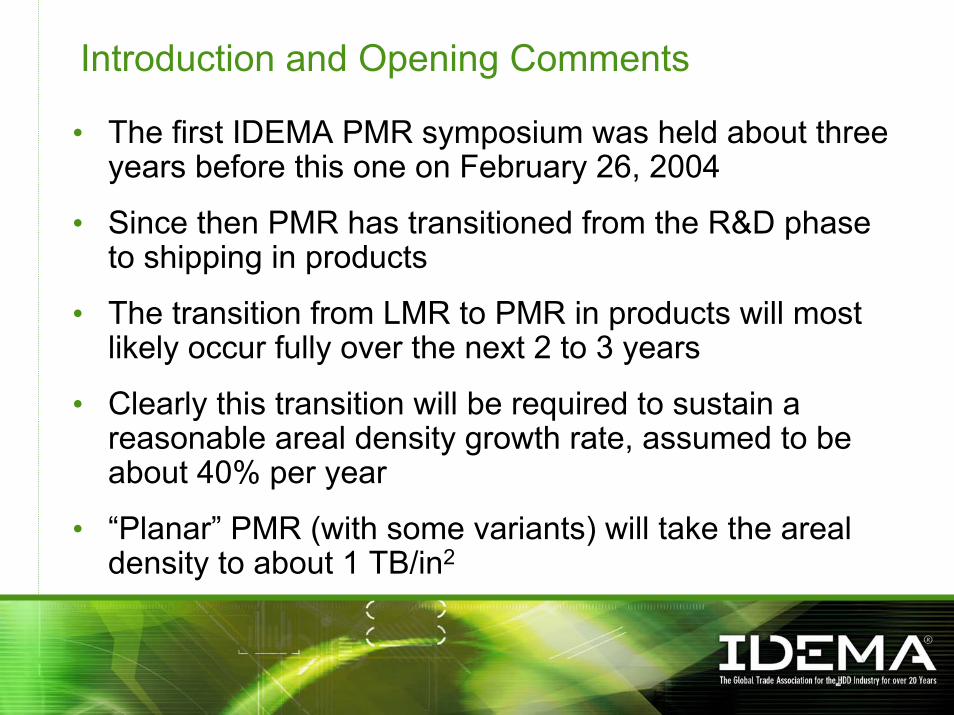
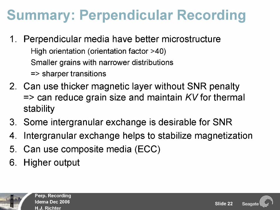
Introduction and Opening Comments
• The first IDEMA PMR symposium was held about three years before this one on February 26, 2004
• Since then PMR has transitioned from the R&D phase to shipping in products
• The transition from LMR to PMR in products will most likely occur fully over the next 2 to 3 years
• Clearly this transition will be required to sustain a reasonable areal density growth rate, assumed to be about 40% per year
• “Planar” PMR (with some variants) will take the areal density to about 1 TB/in2

Structure of the Presentation• The symposium consisted of about 20 presentations and two panel
discussions
• Six presentations were selected to be summarized in this presentation• The presenter is solely responsible for the selection and said selection
should not be construed to be a ranking of the talks in the symposium
• Hopefully the current audience will get a flavor for the breadth of presentations made and be motivated to review these and other presentations fully on the IDEMA website
• The symposium proceedings, along with this presentation, are available to IDEMA members by using the following link:
http://www.idema.org/_smartsite/modules/local/data_file/show_file.php?cmd=doc_all&h=0#
(Or go to www.idema.org, select Document Library, Event Proceedings, PMR Symposium Dec 2006 Presentations)

4
5
6
7
8
9
10
11
12
13
14
15
PERPENDICULAR FILM HEAD PROCESSING PERSPECTIVES
FOR AREAL DENSITY INCREASES
R. E. Fontana, Jr., N. Robertson, M.C. Cyrille, J. Li, J. KatineSan Jose Research Center
Hitachi Global Storage TechnologiesSan Jose, CA
R. E. Fontana, Jr. “Perpendicular Film Head Processing Perspectives for Areal Density Increases” 15December 7, 2006
16
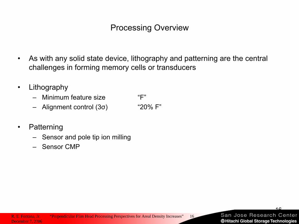
Processing Overview
• As with any solid state device, lithography and patterning are the central challenges in forming memory cells or transducers
• Lithography – Minimum feature size “F”– Alignment control (3σ) “20% F”
• Patterning– Sensor and pole tip ion milling– Sensor CMP
R. E. Fontana, Jr. “Perpendicular Film Head Processing Perspectives for Areal Density Increases” 16December 7, 2006
17
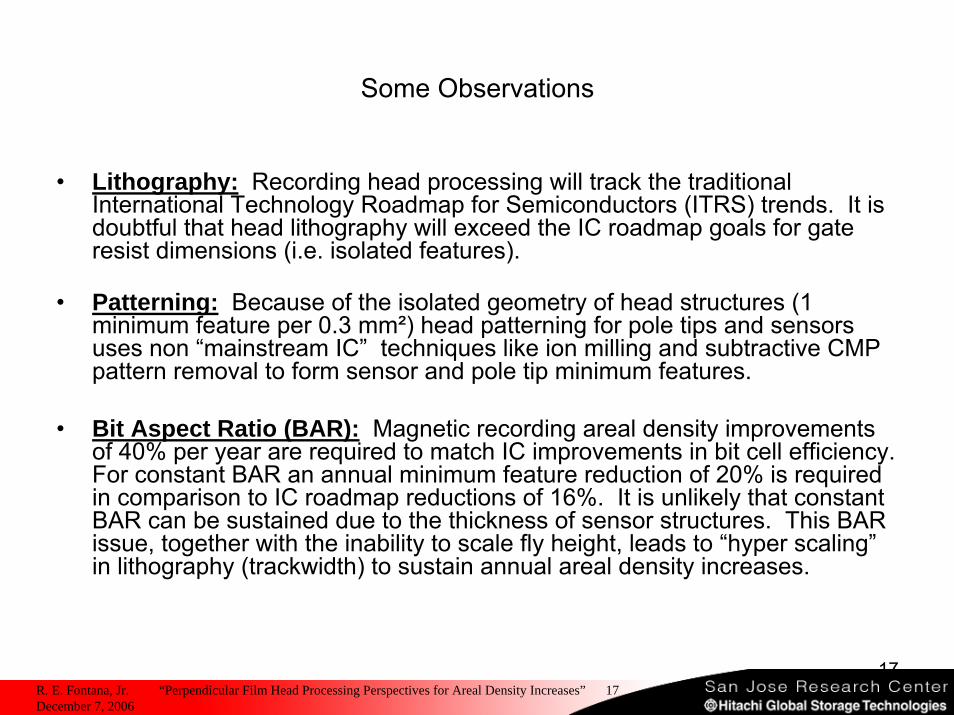
Some Observations
• Lithography: Recording head processing will track the traditional International Technology Roadmap for Semiconductors (ITRS) trends. It is doubtful that head lithography will exceed the IC roadmap goals for gate resist dimensions (i.e. isolated features).
• Patterning: Because of the isolated geometry of head structures (1 minimum feature per 0.3 mm²) head patterning for pole tips and sensors uses non “mainstream IC” techniques like ion milling and subtractive CMP pattern removal to form sensor and pole tip minimum features.
• Bit Aspect Ratio (BAR): Magnetic recording areal density improvements of 40% per year are required to match IC improvements in bit cell efficiency. For constant BAR an annual minimum feature reduction of 20% is required in comparison to IC roadmap reductions of 16%. It is unlikely that constant BAR can be sustained due to the thickness of sensor structures. This BAR issue, together with the inability to scale fly height, leads to “hyper scaling”in lithography (trackwidth) to sustain annual areal density increases.
R. E. Fontana, Jr. “Perpendicular Film Head Processing Perspectives for Areal Density Increases” 17December 7, 2006
18
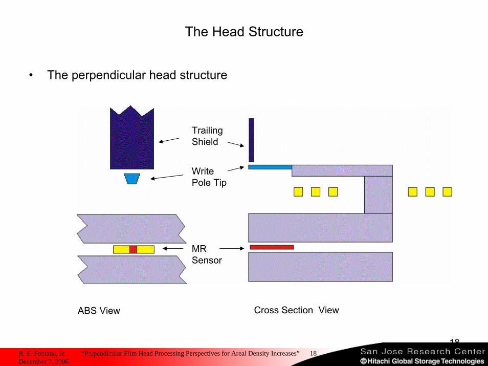
The Head Structure
• The perpendicular head structure
Trailing Shield
Write Pole Tip
MR Sensor
Cross Section ViewABS View
R. E. Fontana, Jr. “Perpendicular Film Head Processing Perspectives for Areal Density Increases” 18December 7, 2006
19
The IC Environment
• IC minimum features, F, are printed on a 2F pitch (equal line and space)
• The smallest IC feature is the gate resist, about 0.6F, and printed on a 4F pitch
• In 2005 the ITRS expanded the concept of lithography nodes to set distinct roadmap goals to the main IC technologies of DRAM, Microprocessors, and FLASH.
• FLASH is now considering printing equal line and space lithography using 2 mask processing, i.e. 2 masks with minimum feature F printed on a 4F pitch and anticipating increase alignment capability of tools to create the equal line and space final structure
R. E. Fontana, Jr. “Perpendicular Film Head Processing Perspectives for Areal Density Increases” 19December 7, 2006
20
Patterning
• Pole tip processing for perpendicular recording has become more ion mill intensive than for a comparable longitudinal recording head
– Perpendicular thin pole tip material ~ 100 nm– Longitudinal thick plated pole tip material ~ 1000 nm– Perpendicular ion milling to form re-entrant feature – Longitudinal ion milling to form a notch and to tune trackwidth
• Sensor processing has now evolved to intensive ion milling for tunnel structures and CMP for liftoff
• Patterning processes for sensor and pole tip formation are converging!!
R. E. Fontana, Jr. “Perpendicular Film Head Processing Perspectives for Areal Density Increases” 20December 7, 2006
21
Summary and Final Observations from a Process Person
• Minimum feature formation will track the ITRS roadmaps. Head dimensions will approach the gate resist dimensions at 500 Gbit/in² areal densities
• Alignment is becoming the critical process issue. Alignment is a key concern for the IC industry and tooling will target delivering 3σ alignment at 20% of minimum feature. Alignment is a vector quantity and perpendicular head alignments rely on one component of the vector, i.e. x and not x and y. NAND Flash is driving both alignment and minimum feature
• As sensor and pole tip thicknesses converge, patterning strategies practiced for the sensor are now being leveraged and utilized for pole tip formation.
A Caution
• Total sensor thickness and spacing do not scale with areal density placing limits on constant BAR recording system designs. The net result is hyper scaling in TW reduction.
• The write head is becoming more complex. Need to have head designs consistent with ITRS roadmap and not exceed it.
R. E. Fontana, Jr. “Perpendicular Film Head Processing Perspectives for Areal Density Increases” 21December 7, 2006
Precision Cleaning Process and Equipment Considerations for PMR media
Dave FrostSenior Director of Business Development
Media Process Equipment
December 7, 2006
23
PMR cleaning “opportunity” comment from leading Industry Analyst
“The (PMR) head-disk interface is arguably the most intricate in the history of the HDD industry………..and cleanliness has both never been more important and less understood”
“Focus on PMR Transition” paperTrendFOCUS 8/1/06
24
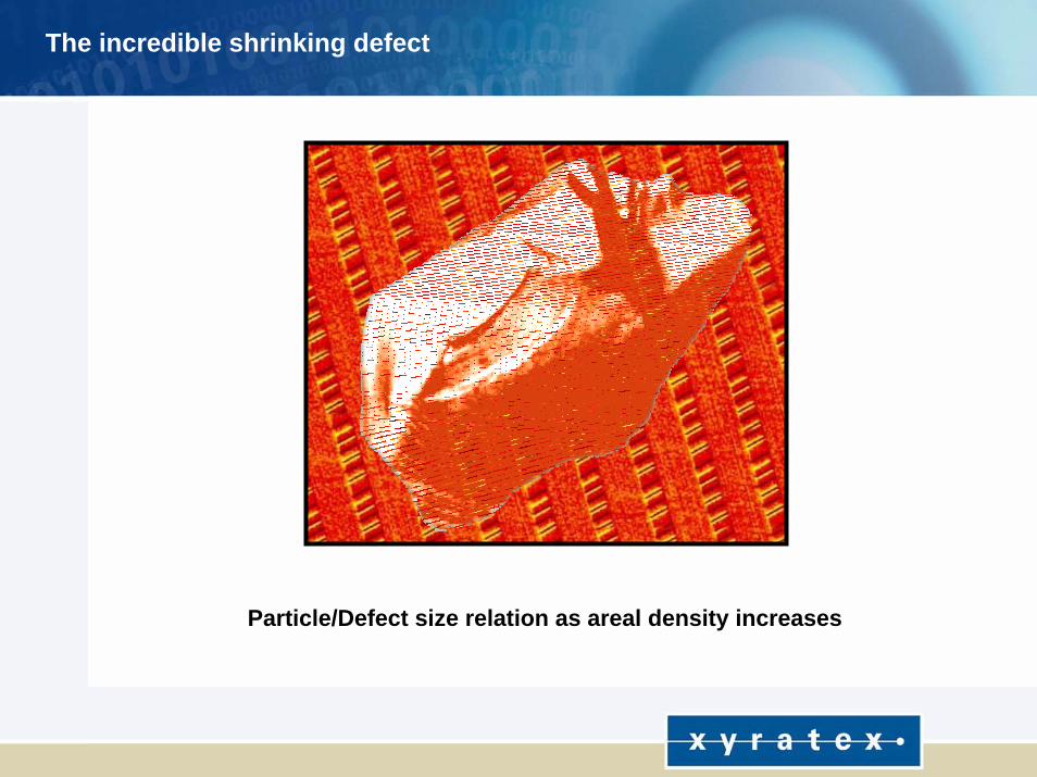
Particle/Defect size as areal density increasesParticle/Defect size relation as areal density increases
The incredible shrinking defect
25
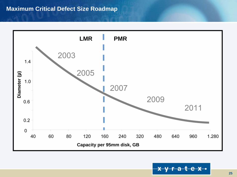
Maximum Critical Defect Size Roadmap
0
0.2
0.6
1.0
1.4
40 60 80 120 160 240 320 480 640 960 1.280
Capacity per 95mm disk, GB
Dia
met
er (µ
) 2005
2003
20112009
2007
LMR PMR
26
Types of Defects to be removed via cleaning
Particles Head/Disk Interface issues that can cause a head crashMagnetic defectsCorrosionUsually can be caught at final test, before shipment
Film or StainsImpairs film adhesion Magnetic defectsCorrosion Difficult to detect and can grow over time, after shipment!
27
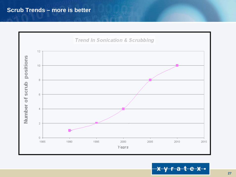
Scrub Trends – more is better
28
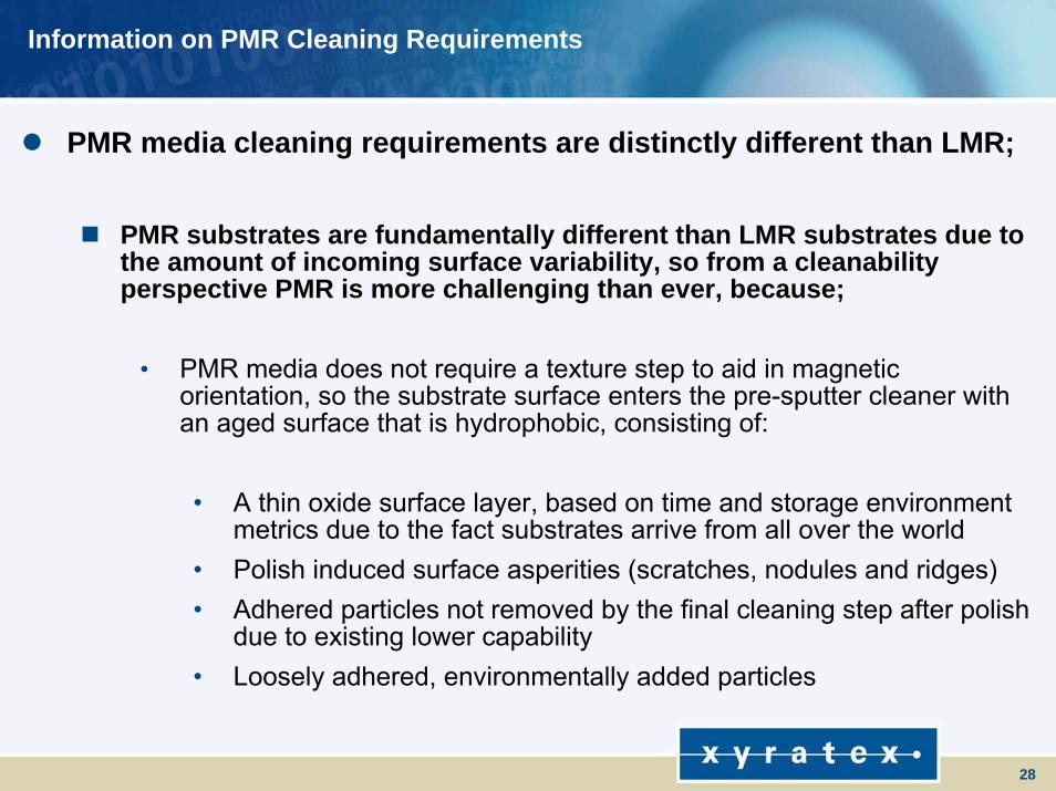
Information on PMR Cleaning Requirements
PMR media cleaning requirements are distinctly different than LMR;
PMR substrates are fundamentally different than LMR substrates due to the amount of incoming surface variability, so from a cleanability perspective PMR is more challenging than ever, because;
• PMR media does not require a texture step to aid in magnetic orientation, so the substrate surface enters the pre-sputter cleaner with an aged surface that is hydrophobic, consisting of:
• A thin oxide surface layer, based on time and storage environment metrics due to the fact substrates arrive from all over the world
• Polish induced surface asperities (scratches, nodules and ridges)• Adhered particles not removed by the final cleaning step after polish
due to existing lower capability • Loosely adhered, environmentally added particles
29
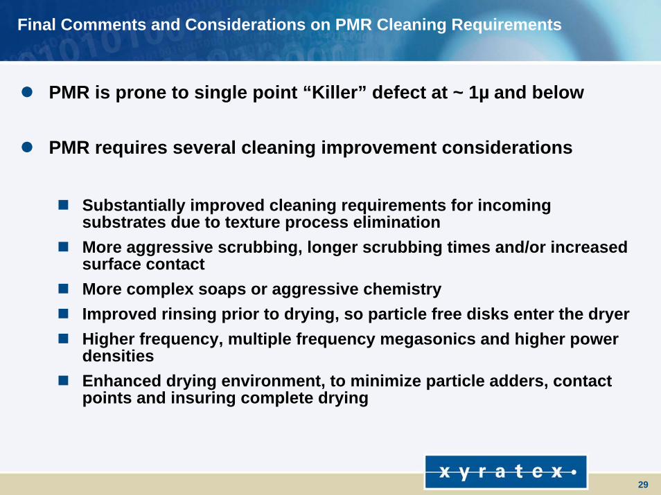
Final Comments and Considerations on PMR Cleaning Requirements
PMR is prone to single point “Killer” defect at ~ 1µ and below
PMR requires several cleaning improvement considerations
Substantially improved cleaning requirements for incoming substrates due to texture process eliminationMore aggressive scrubbing, longer scrubbing times and/or increased surface contactMore complex soaps or aggressive chemistryImproved rinsing prior to drying, so particle free disks enter the dryerHigher frequency, multiple frequency megasonics and higher powerdensitiesEnhanced drying environment, to minimize particle adders, contact points and insuring complete drying
30
Perpendicular Integration:An Industry ChallengeMartin Lynch – Chief Operating OfficerDecember 7, 2006
31
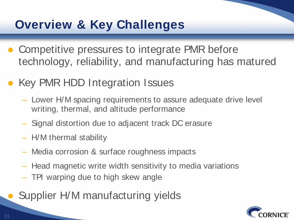
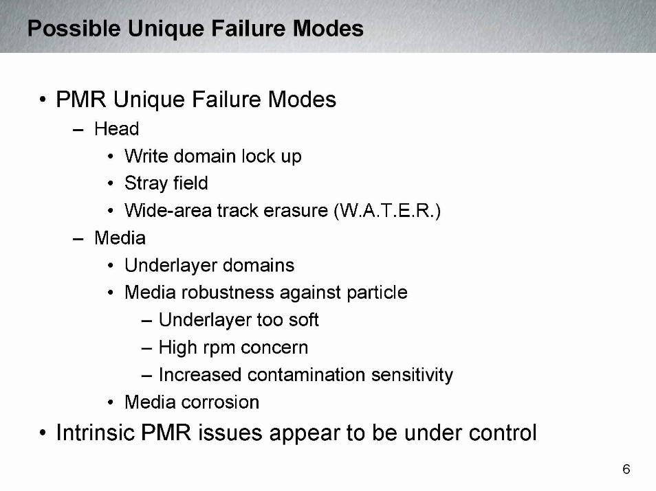
Overview & Key Challenges
Competitive pressures to integrate PMR before technology, reliability, and manufacturing has matured
Key PMR HDD Integration Issues– Lower H/M spacing requirements to assure adequate drive level
writing, thermal, and altitude performance
– Signal distortion due to adjacent track DC erasure
– H/M thermal stability
– Media corrosion & surface roughness impacts
– Head magnetic write width sensitivity to media variations– TPI warping due to high skew angle
Supplier H/M manufacturing yields
32
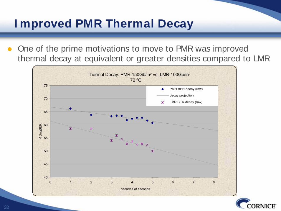
Improved PMR Thermal Decay
One of the prime motivations to move to PMR was improved thermal decay at equivalent or greater densities compared to LMR
Thermal Decay: PMR 150Gb/in2 vs. LMR 100Gb/in2
72 ºC
40
45
50
55
60
65
70
75
0 1 2 3 4 5 6 7 8
decades of seconds
-10l
ogB
ER
PMR BER decay (raw)
decay projection
LMR BER decay (raw)
Thermal Decay: PMR 150Gb/in2 vs. LMR 100Gb/in2
72 ºC
40
45
50
55
60
65
70
75
0 1 2 3 4 5 6 7 8
decades of seconds
-10l
ogB
ER
PMR BER decay (raw)
decay projection
LMR BER decay (raw)
33
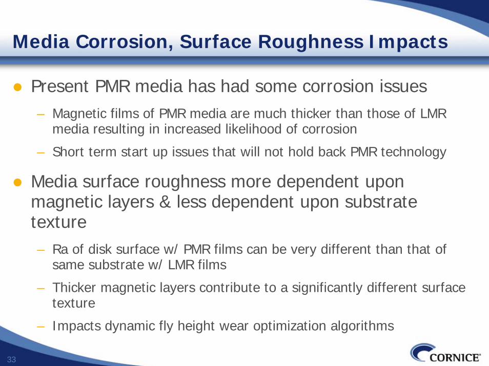
Media Corrosion, Surface Roughness Impacts
Present PMR media has had some corrosion issues– Magnetic films of PMR media are much thicker than those of LMR
media resulting in increased likelihood of corrosion
– Short term start up issues that will not hold back PMR technology
Media surface roughness more dependent upon magnetic layers & less dependent upon substrate texture– Ra of disk surface w/ PMR films can be very different than that of
same substrate w/ LMR films
– Thicker magnetic layers contribute to a significantly different surface texture
– Impacts dynamic fly height wear optimization algorithms
34
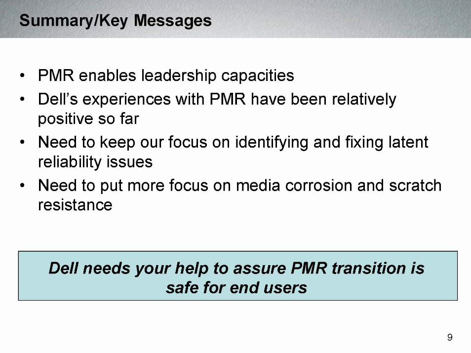
Conclusions
Over 20 years of PMR research and development have made for a fairly smooth transition
Most difficult transition impacts were due to increased sensitivity to H/M spacing requirements
Some initial adjustments optimizing manufacturing processes (supply chain & HDD)
PMR necessitates total optimization across the supply chain and unprecedented level of cooperation
Competitive pressures both within the HDD industry as well as outside will tend to force earlier adoption of new technologies, risking over-commitments
35
36
37
38
39
40
©2006 Information Storage Industry Consortium2006 Information Storage Industry Consortium
Information Storage Industry ConsortiumInformation Storage Industry Consortium
THE THE HDD TECHNOLOGY ROADMAP HDD TECHNOLOGY ROADMAP –– PMR AND BEYONDPMR AND BEYONDPaul D. FrankPaul D. Frank
December 7, 2006December 7, 2006
©2006 Information Storage Industry Consortium2006 Information Storage Industry Consortium
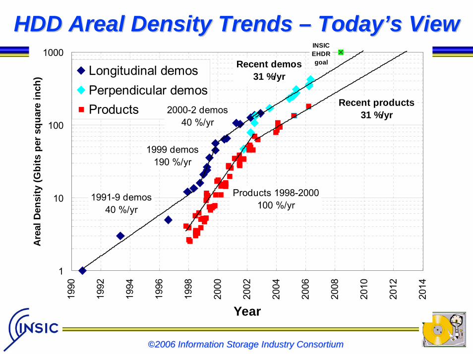
HDD Areal Density Trends HDD Areal Density Trends –– TodayToday’’s Views View
1
10
100
1000
1990
1992
1994
1996
1998
2000
2002
2004
2006
2008
2010
2012
2014
Year
Are
al D
ensi
ty (G
bits
per
squ
are
inch
) Longitudinal demosPerpendicular demosProducts
Products 1998-2000100 %/yr
2000-2 demos40 %/yr
Recent products31 %/yr
INSICEHDR goalRecent demos
31 %/yr
1999 demos190 %/yr
1991-9 demos40 %/yr
©2006 Information Storage Industry Consortium2006 Information Storage Industry Consortium
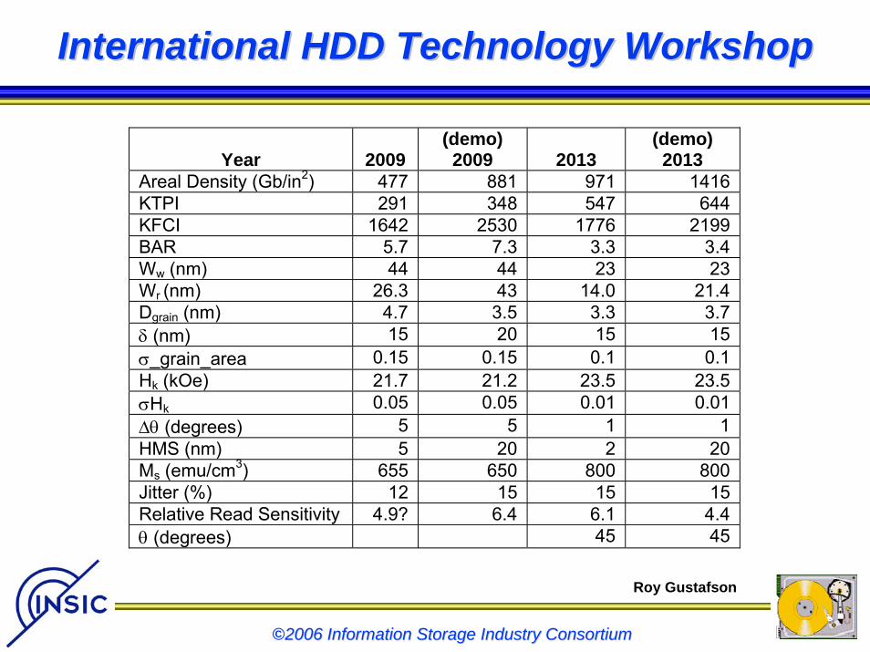
International HDD Technology WorkshopInternational HDD Technology Workshop
Year 2009 (demo) 2009 2013
(demo) 2013
Areal Density (Gb/in2) 477 881 971 1416KTPI 291 348 547 644KFCI 1642 2530 1776 2199BAR 5.7 7.3 3.3 3.4Ww (nm) 44 44 23 23Wr (nm) 26.3 43 14.0 21.4Dgrain (nm) 4.7 3.5 3.3 3.7δ (nm) 15 20 15 15σ_grain_area 0.15 0.15 0.1 0.1Hk (kOe) 21.7 21.2 23.5 23.5σHk 0.05 0.05 0.01 0.01∆θ (degrees) 5 5 1 1HMS (nm) 5 20 2 20Ms (emu/cm3) 655 650 800 800Jitter (%) 12 15 15 15Relative Read Sensitivity 4.9? 6.4 6.1 4.4θ (degrees) 45 45
Roy Gustafson
©2006 Information Storage Industry Consortium2006 Information Storage Industry Consortium
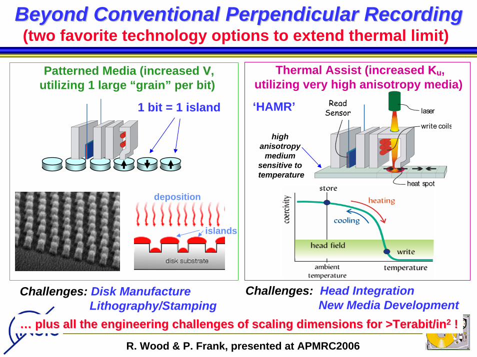
Beyond Conventional PMRBeyond Conventional PMR……
The future is probably ALL perpendicular.Although modeling (and consensus) currently suggests that conventional PMR will not likely get us beyond 0.6 ~ 1.0 Tb/in2, the leading candidate successor technologies, Thermally-Assisted or Heat-Assisted Magnetic Recording (HAMR) and Bit Patterned Media (BPM) are also likely to rely on perpendicular recording, and could perhaps be best thought of as extensions, rather than replacements, of perpendicular recording.
©2006 Information Storage Industry Consortium2006 Information Storage Industry Consortium
The Superparamagnetic EffectThe Superparamagnetic Effect
©2006 Information Storage Industry Consortium
Magnetic stability requires that
KKuuV/kTV/kT > 40 ~ 60> 40 ~ 60where…
Ku = magnetic anisotropy energyV = magnetic grain volumek = Boltzmann’s constantT = absolute temperature
©2006 Information Storage Industry Consortium2006 Information Storage Industry Consortium
GMR laser
write coils
heat spot
Read Sensor
Thermal Assist (increased KKuu,utilizing very high anisotropy media)
(two favorite technology options to extend thermal limit)
deposition
islands
1 bit = 1 island
Patterned Media (increased VV,utilizing 1 large “grain” per bit)
high anisotropy
medium sensitive to temperature
‘HAMR’
Beyond Conventional Perpendicular RecordingBeyond Conventional Perpendicular Recording
Challenges: Disk ManufactureLithography/Stamping
Challenges: Head IntegrationNew Media Development
…… plus all the engineering challenges of scaling dimensions for >plus all the engineering challenges of scaling dimensions for >Terabit/inTerabit/in22 !!
R. Wood & P. Frank, presented at APMRC2006
©2006 Information Storage Industry Consortium2006 Information Storage Industry Consortium
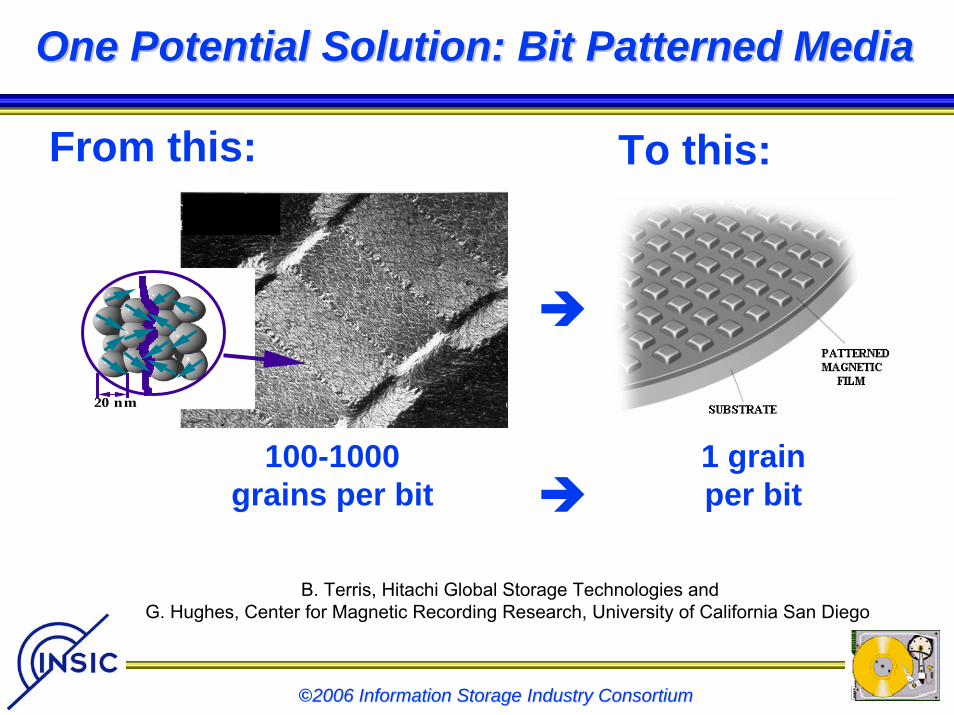
One Potential Solution: Bit Patterned MediaOne Potential Solution: Bit Patterned Media
20 nm
~ 1,000 grains per bit
From this: To this:
100-1000grains per bit
1 grainper bit
B. Terris, Hitachi Global Storage Technologies andG. Hughes, Center for Magnetic Recording Research, University of California San Diego
©2006 Information Storage Industry Consortium2006 Information Storage Industry Consortium
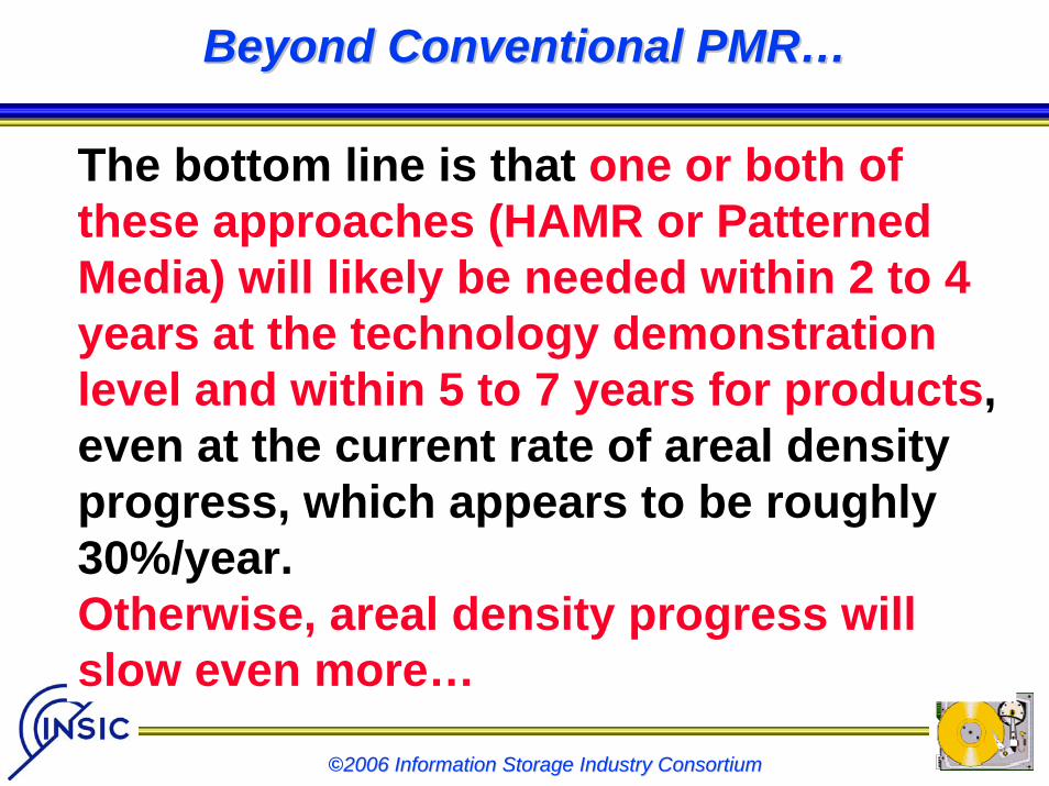
Beyond Conventional PMRBeyond Conventional PMR……
The bottom line is that one or both of these approaches (HAMR or Patterned Media) will likely be needed within 2 to 4 years at the technology demonstration level and within 5 to 7 years for products, even at the current rate of areal density progress, which appears to be roughly 30%/year. Otherwise, areal density progress will slow even more…
©2006 Information Storage Industry Consortium2006 Information Storage Industry Consortium
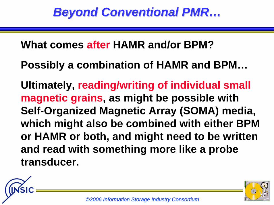
Beyond Conventional PMRBeyond Conventional PMR……
What comes after HAMR and/or BPM?
Possibly a combination of HAMR and BPM…
Ultimately, reading/writing of individual small magnetic grains, as might be possible with Self-Organized Magnetic Array (SOMA) media, which might also be combined with either BPM or HAMR or both, and might need to be written and read with something more like a probe transducer.
©2006 Information Storage Industry Consortium2006 Information Storage Industry Consortium
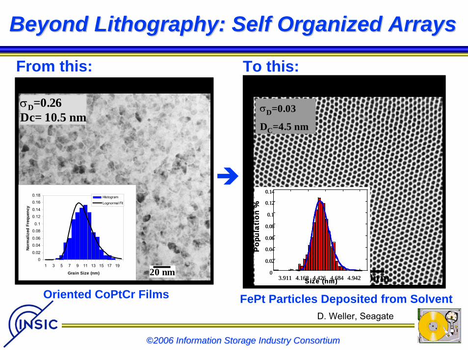
Beyond Lithography: Self Organized ArraysBeyond Lithography: Self Organized Arrays
From this:Grain Diameter= 4.5±0.15nm random
σD=0.03
DC=4.5 nm
0
0.02
0.04
0.06
0.08
0.1
0.12
0.14
3.911 4.168 4.426 4.684 4.942
Pop
ulat
ion
%
Size (nm)
Grain Diameter= 4.5±0.15nm
σD=0.03
DC=4.5 nm
0
0.02
0.04
0.06
0.08
0.1
0.12
0.14
3.911 4.168 4.426 4.684 4.942
Pop
ulat
ion
%
Size (nm)0
0.02
0.04
0.06
0.08
0.1
0.12
0.14
3.911 4.168 4.426 4.684 4.942
Pop
ulat
ion
%
Size (nm)0
0.02
0.04
0.06
0.08
0.1
0.12
0.14
3.911 4.168 4.426 4.684 4.942
Pop
ulat
ion
%
Size (nm)
To this:
20 nm0
0.02
0.04
0.06
0.08
0.1
0.12
0.14
0.16
0.18
1 3 5 7 9 11 13 15 17 19
Grain Size (nm)
Nor
mal
ized
Fre
quen
cy
Histogram
Lognormal Fit
Grain Diameter = 9.9±2.6 nm ∆θ50 = 6.8°
σD=0.26Dc= 10.5 nm
20 nm20 nm0
0.02
0.04
0.06
0.08
0.1
0.12
0.14
0.16
0.18
1 3 5 7 9 11 13 15 17 19
Grain Size (nm)
Nor
mal
ized
Fre
quen
cy
Histogram
Lognormal Fit
Grain Diameter = 9.9±2.6 nm ∆θ50 = 6.8°
σD=0.26Dc= 10.5 nm
Oriented CoPtCr Films FePt Particles Deposited from SolventD. Weller, Seagate
©2006 Information Storage Industry Consortium2006 Information Storage Industry Consortium
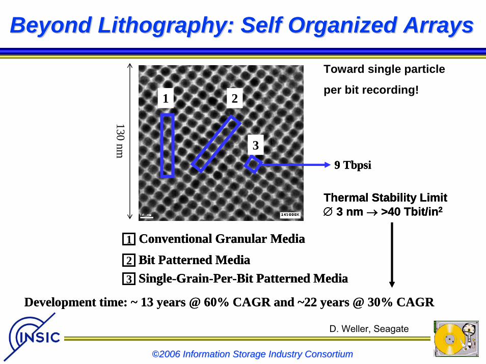
Beyond Lithography: Self Organized ArraysBeyond Lithography: Self Organized Arrays
1
Conventional Granular Media1
1
Conventional Granular Media1 Conventional Granular Media1
130 nm 3
3 Single-Grain-Per-Bit Patterned Media
3
3 Single-Grain-Per-Bit Patterned Media3 Single-Grain-Per-Bit Patterned Media
2
2 Bit Patterned Media
2
2 Bit Patterned Media2 Bit Patterned Media
9 Tbpsi
Thermal Stability Limit∅ 3 nm → >40 Tbit/in2
Development time: ~ 13 years @ 60% CAGR and ~22 years @ 30% CAGR
9 Tbpsi
Thermal Stability Limit∅ 3 nm → >40 Tbit/in2
9 Tbpsi
Thermal Stability Limit∅ 3 nm → >40 Tbit/in2
Development time: ~ 13 years @ 60% CAGR and ~22 years @ 30% CAGR
Toward single particle
per bit recording!
D. Weller, Seagate
©2006 Information Storage Industry Consortium2006 Information Storage Industry Consortium
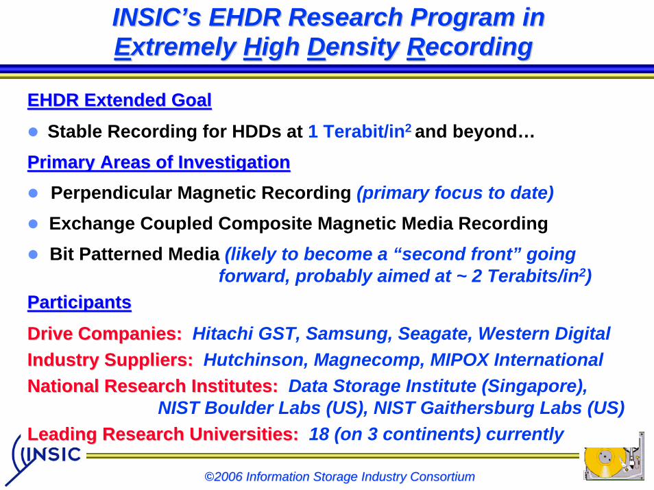
INSICINSIC’’s EHDR Research Program in s EHDR Research Program in EExtremely xtremely HHigh igh DDensity ensity RRecordingecording
EHDR Extended GoalEHDR Extended GoalStable Recording for HDDs at 1 Terabit/in2 and beyond…
Primary Areas of InvestigationPrimary Areas of InvestigationPerpendicular Magnetic Recording (primary focus to date)Exchange Coupled Composite Magnetic Media RecordingBit Patterned Media (likely to become a “second front” going
forward, probably aimed at ~ 2 Terabits/in2)ParticipantsParticipants
Drive Companies:Drive Companies: Hitachi GST, Samsung, Seagate, Western DigitalIndustry Suppliers:Industry Suppliers: Hutchinson, Magnecomp, MIPOX InternationalNational Research Institutes:National Research Institutes: Data Storage Institute (Singapore),
NIST Boulder Labs (US), NIST Gaithersburg Labs (US)Leading Research Universities:Leading Research Universities: 18 (on 3 continents) currently
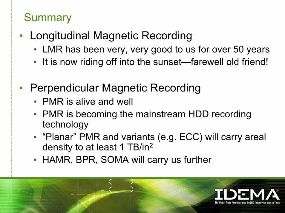
Summary• Longitudinal Magnetic Recording
• LMR has been very, very good to us for over 50 years• It is now riding off into the sunset—farewell old friend!
• Perpendicular Magnetic Recording• PMR is alive and well• PMR is becoming the mainstream HDD recording
technology• “Planar” PMR and variants (e.g. ECC) will carry areal
density to at least 1 TB/in2
• HAMR, BPR, SOMA will carry us further