
6ME4-22 Vibration lab
38
3rd year 6 sem 6ME4-22 Vibration lab 1
Transcript of 6ME4-22 Vibration lab
3rd year 6 sem
6ME4-22 Vibration lab
1

6ME4-22: VIBRATION ENGINEERING LAB.
Credit: 1.5 Max. Marks: 75 0L+0T+3P Exam Hours: 3
CONTACT
SN NAME OF EXPERIMENT
HOURS
1 To verify relation T = 2π� (l/g) for a simple pendulum.
2 To determine radius of gyration of compound pendulum.
3 To determine the radius of gyration of given bar by using bifilar
suspension.
4 To determine natural frequency of a spring mass system.
5 Equivalent spring mass system.
6 To determine natural frequency of free torsional vibrations of single
rotor
system.
i. Horizontal rotor
ii. Vertical rotor
7 To verify the Dunkerley’s rule.
8 Performing the experiment to find out damping co-efficient in case
of free damped torsional vibration
9 To conduct experiment of trifler suspension.
10 Harmonic excitation of cantilever beam using electro-dynamic
shaker and determination of resonant frequencies.
2
Experiment No 1.
AIM: To verify relation T = 2π� (l/g) for a simple pendulum. T=2π ( )
Where T= Periodic Time in Seconds.
l= Length of Pendulum in cms.
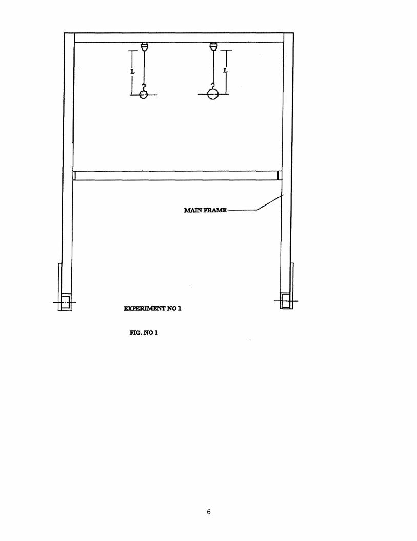
DESCRIPTION OF SET UP :
For conducting the experiment, a bar is supported by nylon thread into the hook. It is
possible to change the length of the pendulum. This makes it possible to study the effect of variation of
length on periodic time.A small ball may be substituted for large ball to illustrate that the period of
oscillation is independent of the mass of ball.
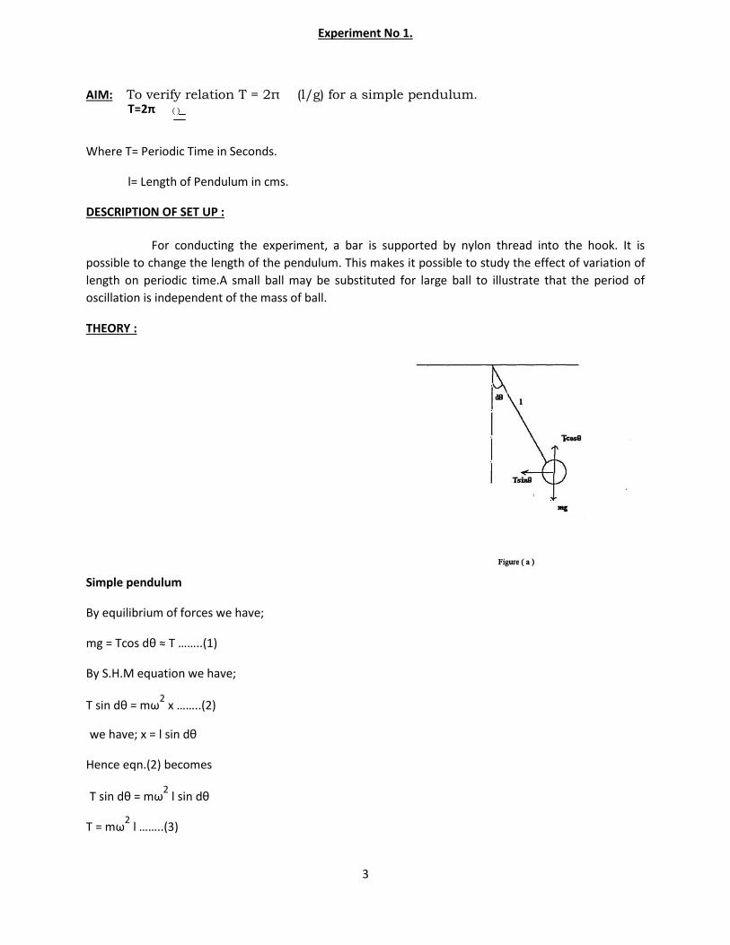
THEORY :
Simple pendulum
By equilibrium of forces we have;
mg = Tcos dθ ≈ T ……..(1)
By S.H.M equation we have;
T sin dθ = mω2 x ……..(2)
we have; x = l sin dθ
Hence eqn.(2) becomes
T sin dθ = mω2 l sin dθ
T = mω2 l ……..(3)
3
From (1) and (3)
mg = mω2 l
ω2 = (g / l) ;ω =
(g/l)
we have ; ω = 2 π / T
Hence,T = 2π ( l
)
PROCEDURE:
a] Attach each ball to one end of the thread.
b] Allow the ball to oscillate and determine the periodic time T by knowing time (for say 10 oscillations).
c] Repeat the experiment by changing the length.
d] Complete the observation table given below.
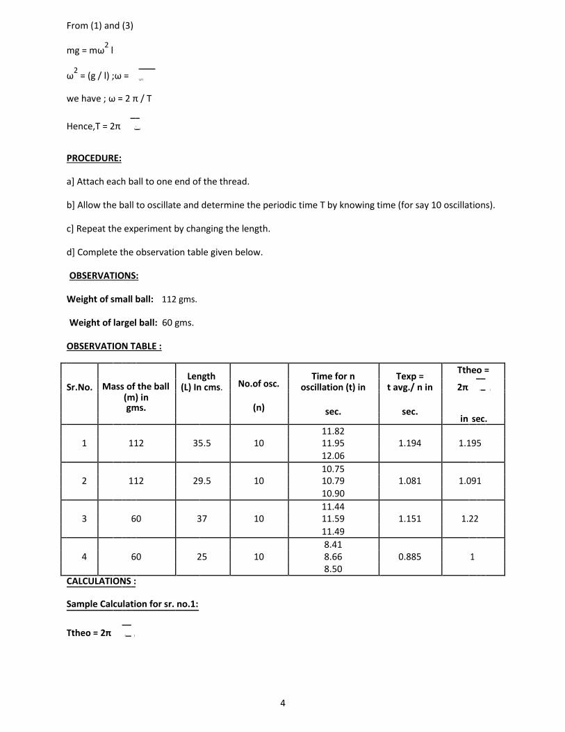
OBSERVATIONS:
Weight of small ball: 112 gms.
Weight of largel ball: 60 gms.
OBSERVATION TABLE :
Length
Time for n Texp =
Ttheo =
Mass of the ball No.of osc.
Sr.No. (L) In cms. oscillation (t) in t avg./ n in 2π ( )
(n)
(m) in gms. sec. sec.
in sec.
11.82
1 112 35.5 10 11.95 1.194 1.195 12.06
10.75
2 112 29.5 10 10.79 1.081 1.091 10.90
11.44
3 60 37 10 11.59 1.151 1.22
11.49
8.41
4 60 25 10 8.66 0.885 1
8.50 CALCULATIONS :
Sample Calculation for sr. no.1:
Ttheo = 2π (
)
4
Ttheo = 2π
.355 9.81
Ttheo = 1.195 secs.
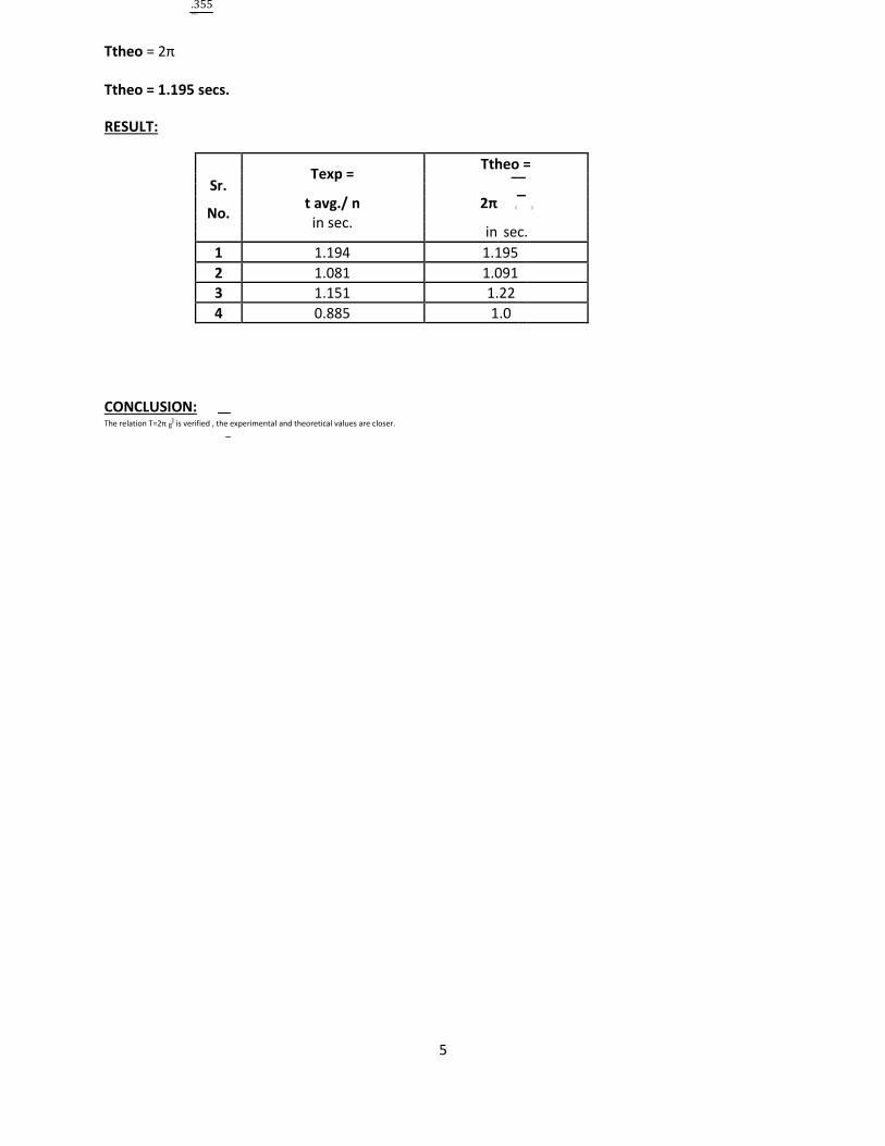
RESULT:
Texp =
Ttheo =
Sr.
t avg./ n 2π ( )
No. in sec.
in sec.
1 1.194 1.195
2 1.081 1.091
3 1.151 1.22
4 0.885 1.0
CONCLUSION: The relation T=2π gl is verified , the experimental and theoretical values are closer.
5
6
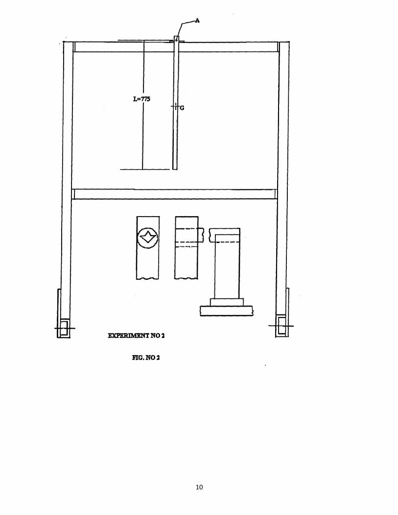
Experiment No 2.
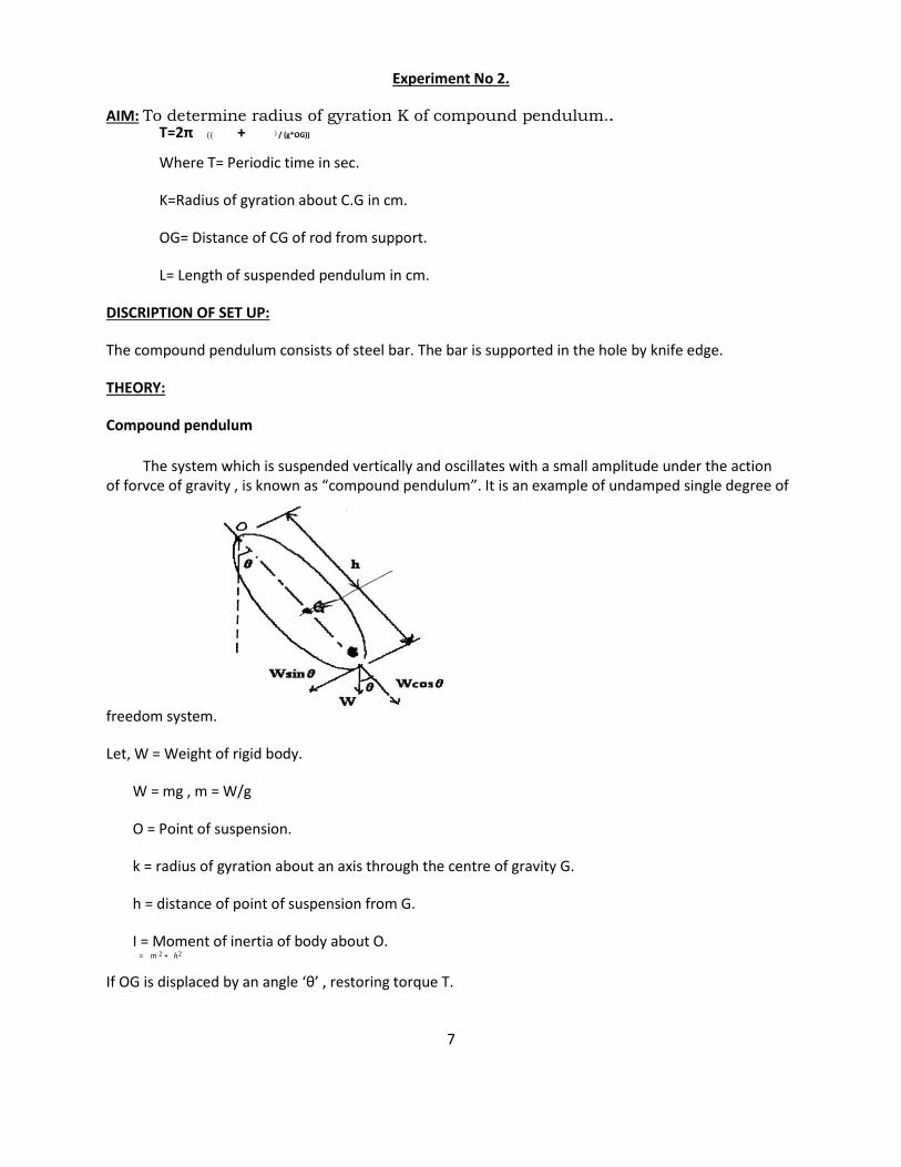
AIM: To determine radius of gyration K of compound pendulum.. T=2π (( + ) / (g*OG))
Where T= Periodic time in sec.
K=Radius of gyration about C.G in cm.
OG= Distance of CG of rod from support.
L= Length of suspended pendulum in cm.
DISCRIPTION OF SET UP:
The compound pendulum consists of steel bar. The bar is supported in the hole by knife edge.
THEORY:
Compound pendulum
The system which is suspended vertically and oscillates with a small amplitude under the action of forvce of gravity , is known as “compound pendulum”. It is an example of undamped single degree of
freedom system.
Let, W = Weight of rigid body.
W = mg , m = W/g
O = Point of suspension.
k = radius of gyration about an axis through the centre of gravity G.
h = distance of point of suspension from G.
I = Moment of inertia of body about O. = m 2 + ℎ2
If OG is displaced by an angle ‘θ’ , restoring torque T.
7
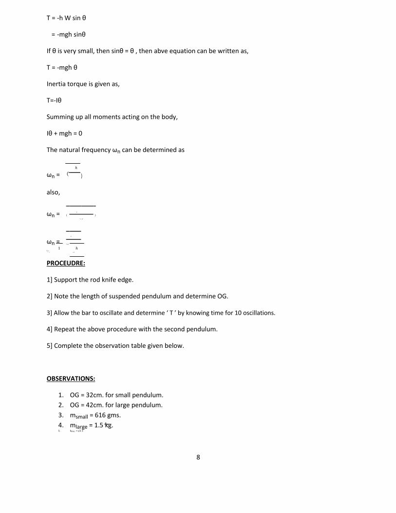
T = -h W sin θ
= -mgh sinθ
If θ is very small, then sinθ = θ , then abve equation can be written as,
T = -mgh θ
Inertia torque is given as,
T=-Iθ
Summing up all moments acting on the body,
Iθ + mgh = 0
The natural frequency ωn can be determined as
ωn = ( ℎ
)
also,
ωn = (
ℎ
)
²+ ℎ²
ωn = ℎ
²+ℎ² 1 ℎ
fn
=2 ²+ℎ²
PROCEUDRE:
1] Support the rod knife edge.
2] Note the length of suspended pendulum and determine OG.
3] Allow the bar to oscillate and determine ‘ T ’ by knowing time for 10 oscillations.
4] Repeat the above procedure with the second pendulum.
5] Complete the observation table given below.
OBSERVATIONS:
1. OG = 32cm. for small pendulum. 2. OG = 42cm. for large pendulum.
3. msmall = 616 gms.
4. mlarge = 1.5 kg. 5. ktheo. = L/2 3
8
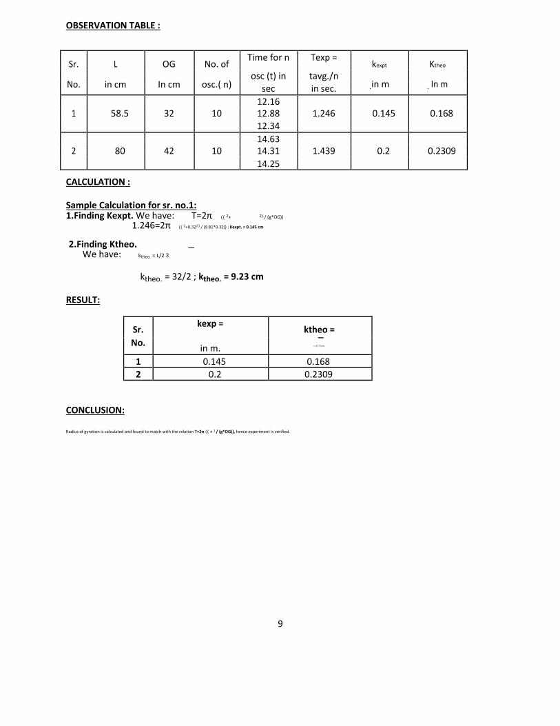
OBSERVATION TABLE :
Sr. L OG No. of Time for n Texp =
kexpt Ktheo
osc (t) in tavg./n No. in cm In cm osc.( n) .in m . In m sec in sec.
12.16
1 58.5 32 10 12.88 1.246 0.145 0.168
12.34
14.63
2 80 42 10 14.31 1.439 0.2 0.2309
14.25
CALCULATION :
Sample Calculation for sr. no.1: 1.Finding Kexpt. We have: T=2π (( 2+ 2) / (g*OG))
1.246=2π (( 2+0.322) / (9.81*0.32)) ; Kexpt. = 0.145 cm
2.Finding Ktheo. We have: ktheo. = L/2 3
ktheo. = 32/2 ; ktheo. = 9.23 cm
RESULT:
Sr. kexp =
ktheo =
No.
in m. = L/2 3 in m.
1 0.145 0.168
2 0.2 0.2309
CONCLUSION:
Radius of gyration is calculated and found to match with the relation T=2π (( + ) / (g*OG)), hence experiment is verified.
9
10
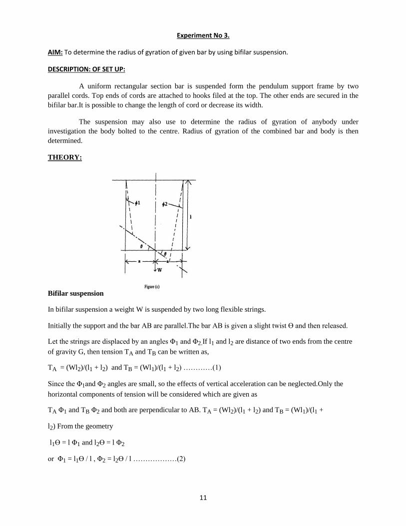
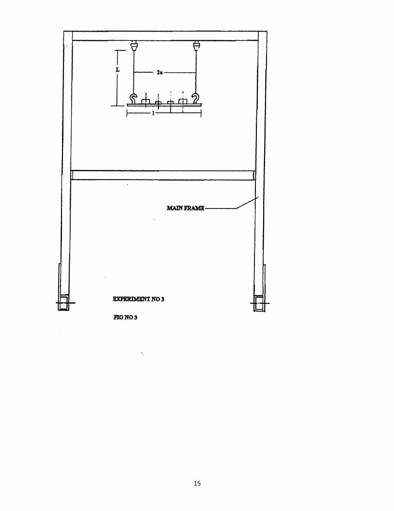
Experiment No 3.
AIM: To determine the radius of gyration of given bar by using bifilar suspension.
DESCRIPTION: OF SET UP:
A uniform rectangular section bar is suspended form the pendulum support frame by two
parallel cords. Top ends of cords are attached to hooks filed at the top. The other ends are secured in the
bifilar bar.It is possible to change the length of cord or decrease its width.
The suspension may also use to determine the radius of gyration of anybody under
investigation the body bolted to the centre. Radius of gyration of the combined bar and body is then
determined.
THEORY:
Bifilar suspension
In bifilar suspension a weight W is suspended by two long flexible strings.
Initially the support and the bar AB are parallel.The bar AB is given a slight twist Ɵ and then released.
Let the strings are displaced by an angles Φ1 and Φ2.If l1 and l2 are distance of two ends from the centre
of gravity G, then tension TA and TB can be written as,
TA = (Wl2)/(l1 + l2) and TB = (Wl1)/(l1 + l2) …………(1)
Since the Φ1and Φ2 angles are small, so the effects of vertical acceleration can be neglected.Only the
horizontal components of tension will be considered which are given as
TA Φ1 and TB Φ2 and both are perpendicular to AB. TA = (Wl2)/(l1 + l2) and TB = (Wl1)/(l1 +
l2) From the geometry
l1Ɵ = l Φ1 and l2Ɵ = l Φ2
or Φ1 = l1Ɵ / l , Φ2 = l2Ɵ / l ………………(2)
11
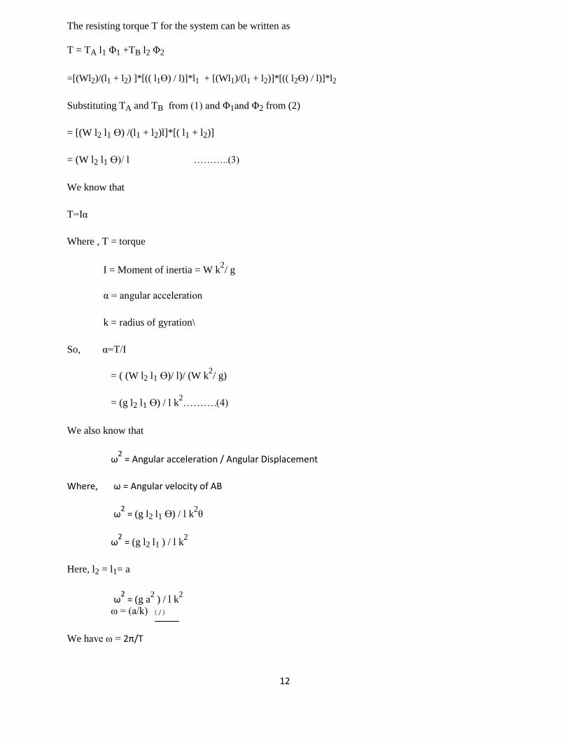
The resisting torque T for the system can be written as
T = TA l1 Φ1 +TB l2 Φ2
=[(Wl2)/(l1 + l2) ]*[(( l1Ɵ) / l)]*l1 + [(Wl1)/(l1 + l2)]*[(( l2Ɵ) / l)]*l2
Substituting TA and TB from (1) and Φ1and Φ2 from (2)
= [(W l2 l1 Ɵ) /(l1 + l2)l]*[( l1 + l2)]
= (W l2 l1 Ɵ)/ l ………..(3)
We know that
T=Iα
Where , T = torque
I = Moment of inertia = W k2/ g
α = angular acceleration
k = radius of gyration\
So, α=T/I
= ( (W l2 l1 Ɵ)/ l)/ (W k2/ g)
= (g l2 l1 Ɵ) / l k2……….(4)
We also know that
ω2 = Angular acceleration / Angular Displacement
Where, ω = Angular velocity of AB
ω2 = (g l2 l1 Ɵ) / l k
2θ
ω2 = (g l2 l1 ) / l k
2
Here, l2 = l1= a
ω2 = (g a
2 ) / l k
2
ω = (a/k) ( / )
We have ω = 2π/T
12
Hence T = 2π *(k/a) ( / ) ………(5)
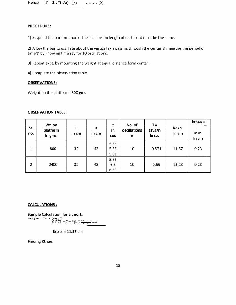
PROCEDURE:
1] Suspend the bar form hook. The suspension length of each cord must be the same.
2] Allow the bar to oscillate about the vertical axis passing through the center & measure the periodic time‘t’ by knowing time say for 10 oscillations.
3] Repeat expt. by mounting the weight at equal distance form center.
4] Complete the observation table.
OBSERVATIONS:
Weight on the platform : 800 gms
OBSERVATION TABLE :
Wt. on
t No. of T =
ktheo =
Sr. L a Kexp.
=L/2 3
platform in oscillations tavg/n
no. In cm in cm In cm in m.
In gms. sec n In sec
In cm
5.56
1 800 32 43 5.66 10 0.571 11.57 9.23
5.91
5.56
2 2400 32 43 6.5 10 0.65 13.23 9.23
6.53
CALCULATIONS :
Sample Calculation for sr. no.1: Finding Kexp. T = 2π *(k/a) ( / )
0.571 = 2π *(k/23) (32/9.81)
Kexp. = 11.57 cm
Finding Ktheo.
13
ktheo = L/2 3 ktheo = 32/2 3
ktheo = 9.23 cm
RESULT:
Sr. Wt. on
L. Kexp. Ktheo. platform
no. In cm In cm In cm in gm
1 800 32 11.57 9.23
2 2400 32 13.23 9.23
CONCLUSION:
1. As length of cord decreases the radius of gyration decreases.
2. Differences in the theoretical ‘k’ experimental values of ‘k’ are due to error in nothing down the time period.
14
15
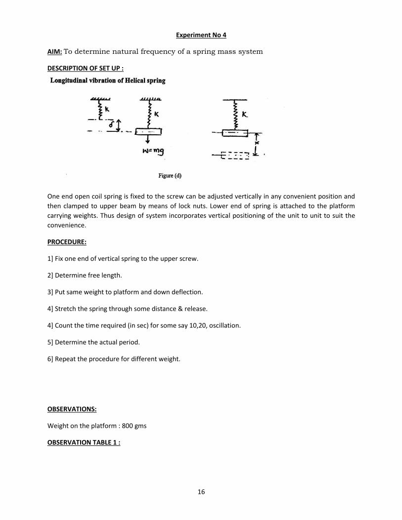
Experiment No 4
AIM: To determine natural frequency of a spring mass system
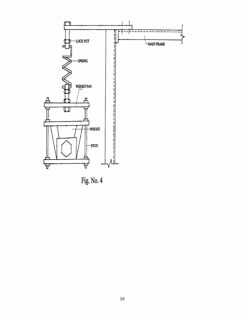
DESCRIPTION OF SET UP :
One end open coil spring is fixed to the screw can be adjusted vertically in any convenient position and
then clamped to upper beam by means of lock nuts. Lower end of spring is attached to the platform
carrying weights. Thus design of system incorporates vertical positioning of the unit to unit to suit the
convenience.
PROCEDURE:
1] Fix one end of vertical spring to the upper screw.
2] Determine free length.
3] Put same weight to platform and down deflection.
4] Stretch the spring through some distance & release.
4] Count the time required (in sec) for some say 10,20, oscillation.
5] Determine the actual period.
6] Repeat the procedure for different weight.
OBSERVATIONS:
Weight on the platform : 800 gms
OBSERVATION TABLE 1 :
16
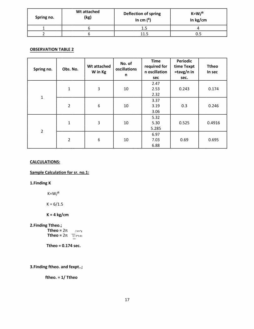
Spring no.
Wt attached (kg)
Deflection of spring K=W/ᵟ In cm (ᵟ) In kg/cm
1 6 1.5 4
2 6 11.5 0.5
OBSERVATION TABLE 2
No. of
Time Periodic Wt attached required for time Texpt Ttheo Spring no. Obs. No. oscillations
W in Kg n oscillation =tavg/n in In sec n
sec sec.
2.47
1 3 10 2.53 0.243 0.174
1 2.32
3.37
2 6 10 3.19 0.3 0.246
3.06
5.32
1 3 10 5.30 0.525 0.4916
2 5.285
6.97
2 6 10 7.03 0.69 0.695
6.88
CALCULATIONS:
Sample Calculation for sr. no.1:
1.Finding K
K=W/ᵟ
K = 6/1.5
K = 4 kg/cm
2.Finding Ttheo.; Ttheo = 2π / km*g Ttheo = 2π 3/ 4*9.81
Ttheo = 0.174 sec.
3.Finding ftheo. and fexpt..;
ftheo. = 1/ Ttheo
17
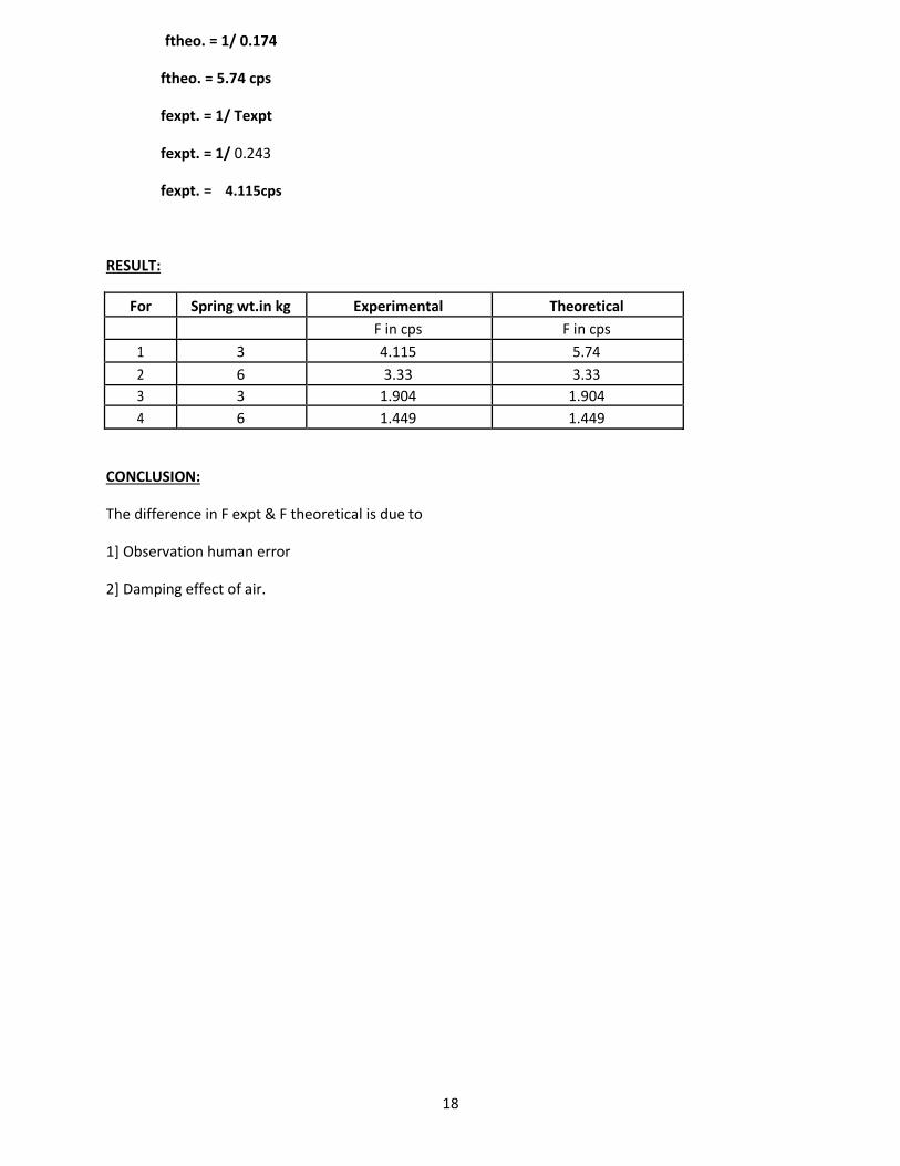
ftheo. = 1/ 0.174
ftheo. = 5.74 cps
fexpt. = 1/ Texpt
fexpt. = 1/ 0.243
fexpt. = 4.115cps
RESULT:
For Spring wt.in kg Experimental Theoretical
F in cps F in cps
1 3 4.115 5.74
2 6 3.33 3.33
3 3 1.904 1.904
4 6 1.449 1.449
CONCLUSION:
The difference in F expt & F theoretical is due to
1] Observation human error
2] Damping effect of air.
18
19
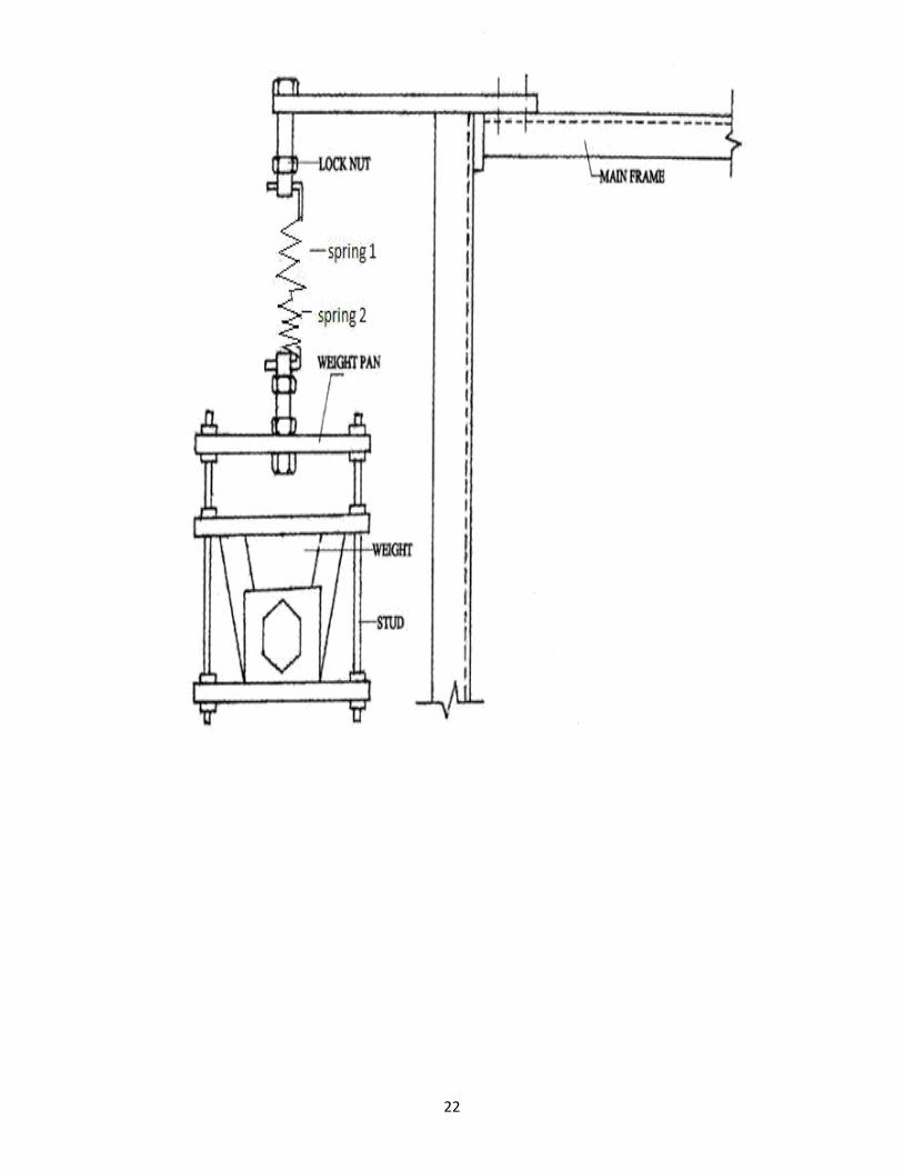
Experiment No 5.
AIM: Equivalent spring mass system
DESCRIPTION OF SET UP:
Fig .shows the general arrangement of experiment setup. It’s consist of fixed support of which there is hole where spring can be attached through the hook.
THEORY:
Spring in Series:
Let Ke =Equivalent stiffness of system
K1,K2 =Deflection of spring.
The total definition of the system is equal to the sum of deflection of individual springs.
X =X1 + X2 +X3 +----- 1 = 11 + 12 + 13 + ------------
Thus the springs are connected in series the reciprocal of equivalent spring stiffness is equal to the sum of reciprocal of individual spring stuffiness.
PROCEDURE:
1. first the tension spring is attached is attached to the support with load no attached to it and it’s length is measure (pitch).
2. Then dead wt is attached to that spring with the help of hook and again length is measured. 3. Same procedure is applied for the spring 2 of different stiffness.
4. Then spring i.e spring 1 and spring 2 connected in series and length is measured then dead wt. is
attached to spring and length is measured.
Observations:
For Spring 1:
Initial pitch = 8mm
Final pitch (with load) = 11mm Load = 1.5kg
Deflection = 3mm
For Spring 2:
Initial pitch = 7mm
20
Final pitch (with load) = 8.5mm Load = 4.872kg
Deflection = 1.5mm
For Springs in series:
Initial length = 24cm
Final length(with load) = 27.8cm Load = 1.5kg
Deflection = 3.8cm
CALCULATIONS:
For Spring 1:
K1 = Load*9.81/defn
K1 = 1.5*9.81/0.003
K1 = 4905 N/m
For Spring 2:
K2 = Load*9.81/defn
K2 = 4.872*9.81/0.0015
K2 = 31862.88 N/m
For Springs in series:
Kexpt = Load*9.81/defn
ωnexpt = Kexpt /m
Kexpt = 1.5*9.81/0.038 ωnexpt = 3872.4 /1.5
Kexpt =3872.4 N/m ωnexpt = 50.8 rad/sec.
1/Ktheo = 1/k1 +1/k2 ωnexpt = Kexpt /m
Ktheo = 4250.65N /m ωnexpt = 53.28 rad/sec.
RESULT:
Kexp =3872.4 N/m , Wexp = 50.81 rad/sec
K th = 4250.66 N/m, W th = 53.28 rad/sec
CONCLUSION:
The theoretical and experimental value of equivalent stiffness were found to almost equal.
21
22
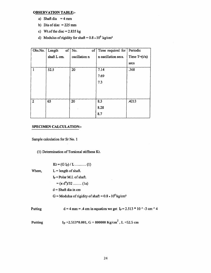
Experiment No 6.
AIM:To determine natural frequency of free torsional vibrations of single rotor
system.
A.Horizontal rotor
B.Vertical rotor
Horizontal rotor
DISCRIPTION OF SET UP:
The arrangement is an shown in fig one end of shift is gripped in dule and a flywheel free to rotate in ball bearing in fixed to other end of shaft.
The bracket with fixed end shaft can be conveniently damped at any position along beam. Thus length of
shaft can be varied during experiment, especially designed b chucks are used for clamping end of shaft.
The ball bearing support to flywheel provides negligible acting support during experiment. The bearing
housing is fixed to side member of main frame.
PROCEDURE:
1] Fix bracket at convenient position along lever beam.
2] Grip one end of shaft at bracket by means of chucks.
3] Fix rotor onto through end of shaft.
4] Twist the rotor through semi cycle and release.
5] Note down time required for 10 oscillations.
6] Repeat procedure for different length of shaft.
23
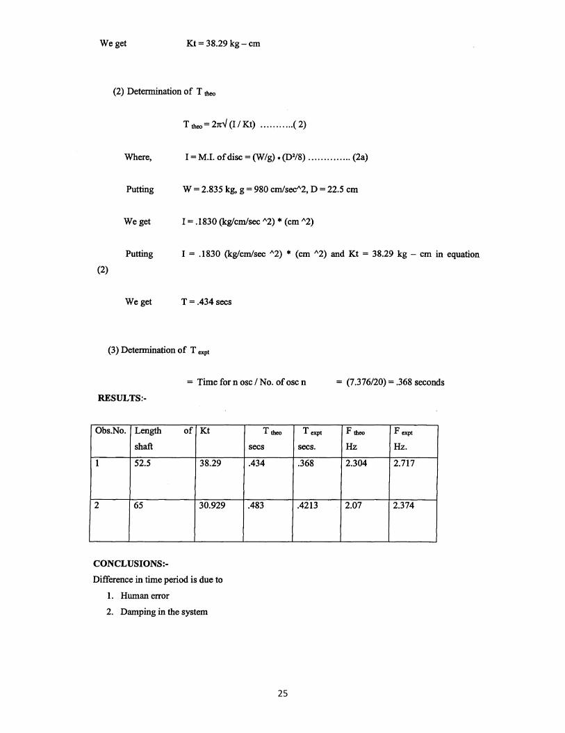
Putting IP =2.513*0.001, G = 800000 Kg/cm2 , L =52.5 cm
24
25
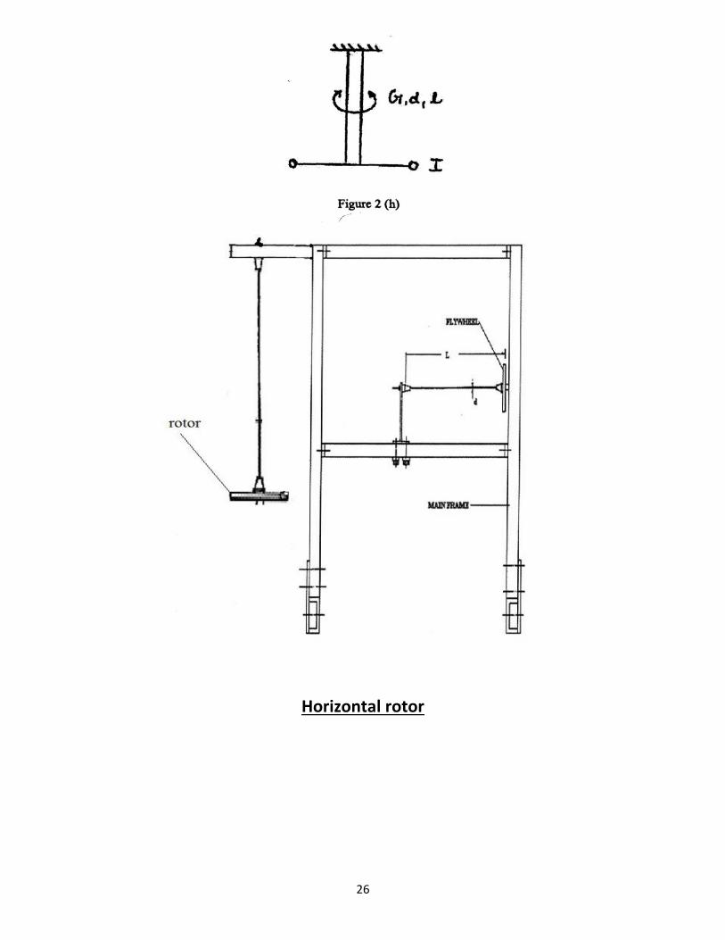
Horizontal rotor
26
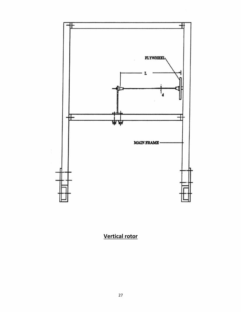
Vertical rotor
27
Experiment No 07.
DUNKERLEY’S RULE
AIM:
1
+= 1
1
To verify Dunkerley’s
+ ^ ^ ^
Where F = Natural frequency of beam with central load w.
FL=Natural frequency of given beam with central load to be calculated as: 48 Fb =
4 ^2 ^3 L = Length of beam
W = Central Load.
Fb =Natural Frequency
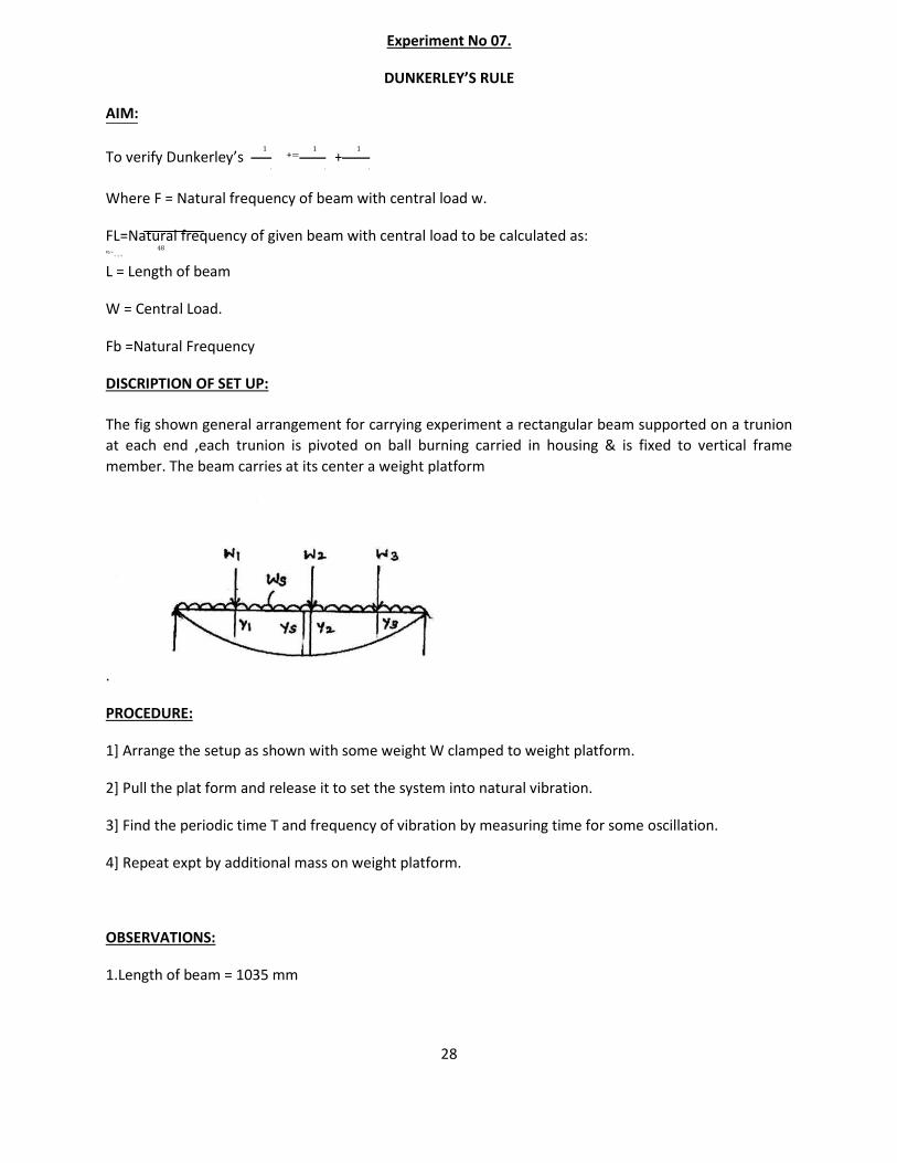
DISCRIPTION OF SET UP:
The fig shown general arrangement for carrying experiment a rectangular beam supported on a trunion
at each end ,each trunion is pivoted on ball burning carried in housing & is fixed to vertical frame
member. The beam carries at its center a weight platform
.
PROCEDURE:
1] Arrange the setup as shown with some weight W clamped to weight platform.
2] Pull the plat form and release it to set the system into natural vibration.
3] Find the periodic time T and frequency of vibration by measuring time for some oscillation.
4] Repeat expt by additional mass on weight platform.
OBSERVATIONS:
1.Length of beam = 1035 mm
28
2.Sectional area of beam = (25*6) mm2
3.Weight of the beam =1.215 kg
4.wt per cm of beam weight = w/l = 1.1739 kg/m.
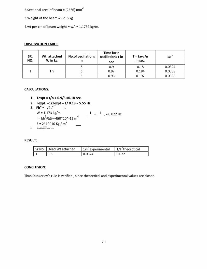
OBSERVATION TABLE:
SR. Wt. attached No.of oscillations Time for n
T = tavg/n
oscillations t in 1/F2
NO. W in kg n sec In sec.
5 0.9 0.18 0.0324 1 1.5 5 0.92 0.184 0.0338
5 0.96 0.192 0.0368
CALCULATIONS:
1. Texpt = t/n = 0.9/5 =0.18 sec. 2. Fexpt. =1/Texpt = 1/ 0.18 = 5.55 Hz 3. Fb
2 = /2L
2 * / ^2
W = 1.173 kg/m
I = bh3/12 = 450*10^-12 m
4
E = 2*10^10 Kg / m2
48
4. FL = 4 ^2 ^3 = 8.034 Hz 5. By Dunkerley’s formulae 1^ +=
RESULT:
1 + 1 , = 0.022 Hz ̂ ^
Sr No Dead Wt attached 1/F2experimental 1/F
2theorotical
1 1.5 0.0324 0.022
CONCLUSION:
Thus Dunkerley’s rule is verified , since theoretical and experimental values are closer.
29
30
Experiment No 08.
AIM: Performing the experiment to find out damping co-efficient in case of free damped
torsional vibration.
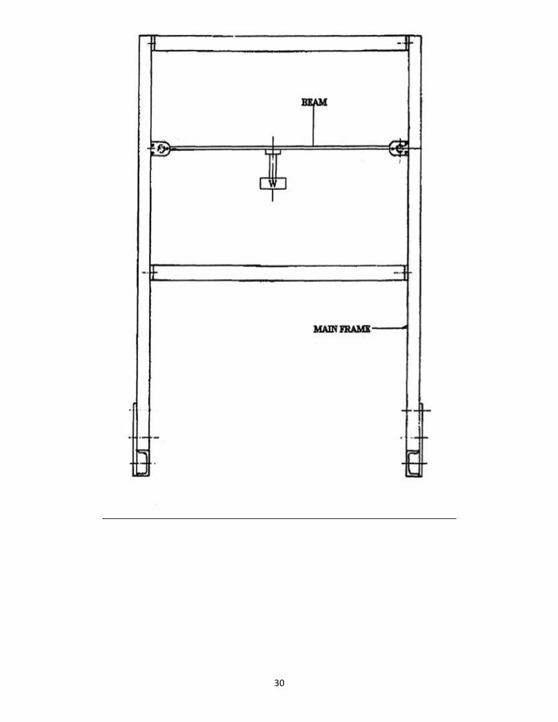
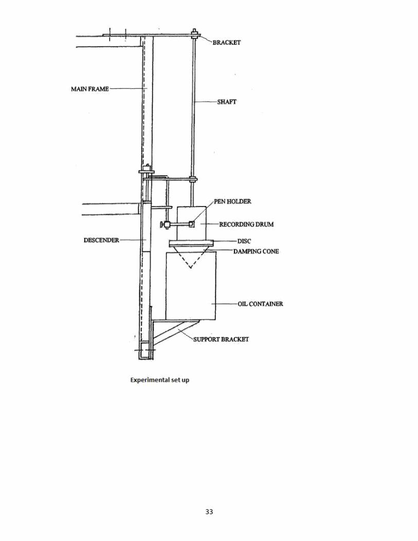
DESCRIPTION OF SET UP:
The fig shows general arrangement for experiment. It consists of long elastic shaft gripped at upper end
by chuck in bracket. The bracket is clamped to upper beam of main frame. A heavy flywheel Clamped to
lower end of shaft suspended from bracket, this drum is immersed in oil which provides damping. Rotor
can be taken up and down for varying depth of immersion of damping drum, depth of immersion can be
read on scale.
PROCEDURE:
1] With no container allow flywheel to oscillate and measure time for 10 Oscillations.
2] Put thin mineral oil in drum and note depth of immersion.
3] Allow flywheel to vibrate.
4] Put sketching pen in bucket.
5] Allow pen to descend see that pen always makes contact with paper and record oscillations.
6] Measure time for some oscillations by means of stop watch.
7] Determine amplitudes of any positions.
OBSERVATION TABLE:
Sr. Damping medium Xn Xn+1
no.
1 Air 1.4 1.3
2 Water 1.15 0.6
3 Oil 1 0.6
31
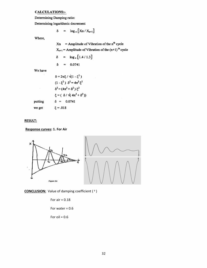
RESULT:
Response curves: 1. For Air
CONCLUSION: Value of damping coefficient ( ᶳ )
For air = 0.18
For water = 0.6
For oil = 0.6
32
33
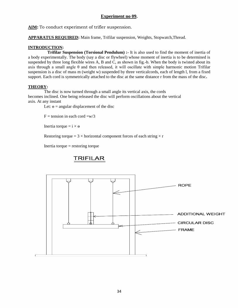
Experiment no 09.
AIM: To conduct experiment of trifler suspension.
APPARATUS REQUIRED: Main frame, Trifilar suspension, Weights, Stopwatch,Thread.
INTRODUCTION: Trifilar Suspension (Torsional Pendulum) :- It is also used to find the moment of inertia of
a body experimentally. The body (say a disc or flywheel) whose moment of inertia is to be determined is suspended by three long flexible wires A, B and C, as shown in fig.-b. When the body is twisted about its
axis through a small angle θ and then released, it will oscillate with simple harmonic motion Trifilar suspension is a disc of mass m (weight w) suspended by three verticalcords, each of length l, from a fixed
support. Each cord is symmetrically attached to the disc at the same distance r from the mass of the disc.
THEORY: The disc is now turned through a small angle its vertical axis, the cords
becomes inclined. One being released the disc will perform oscillations about the vertical axis. At any instant
Let: ѳ = angular displacement of the disc
F = tension in each cord =w/3
Inertia torque = i × ѳ
Restoring torque = 3 × horizontal component forces of each string × r
Inertia torque = restoring torque
34
FORMULA USED:
Time period T= t/n, sec Natural Frequency fn = 1/T Hz Mass of the body (m) = --------kg.
Distance of each wire from the axis of the disc (r) = ------- metres.
=
= 2in kg- 2
PROCEDURE:
1. Hang the plate from chucks with 3 strings of equal lengths at equal angular intervals (1200 each)
2. Give the plate a small twist about its polar axis
3. Measure the time taken, for 5 or 10 oscillations.
4. Repeat the experiment by changing the lengths of strings and adding weights.
OBSERVATION:
S.No. Added,mass, Time for N Time period Natural
m, kg oscillations, T, sec frequency
t, sec fn, Hz
1
2
4
PRECAUTIONS:
1. Tight the drill chucks properly.
2. Length of each cord should be equal.
RESULT :
35
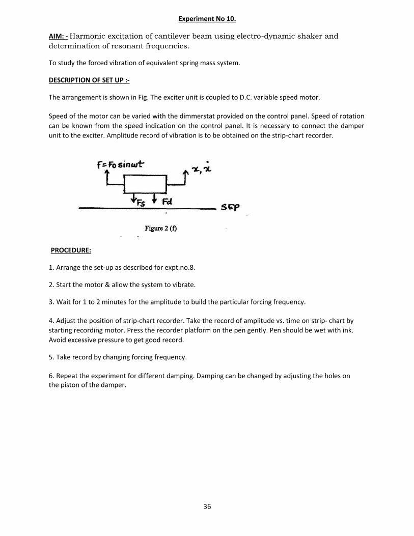
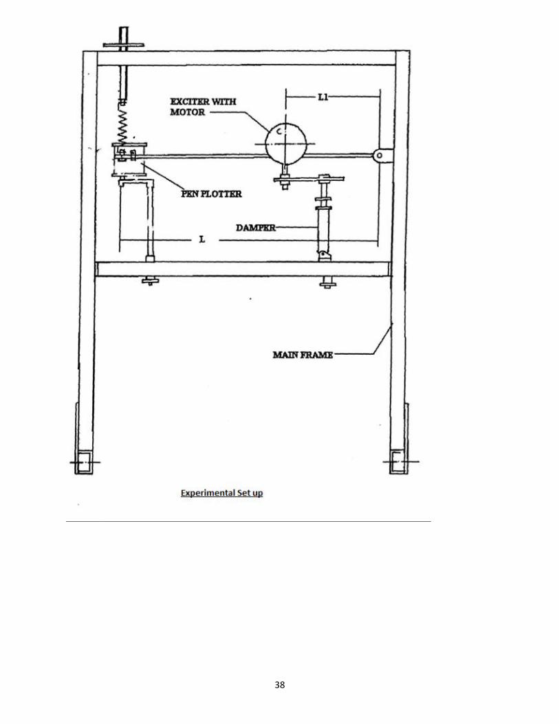
Experiment No 10.
AIM: - Harmonic excitation of cantilever beam using electro-dynamic shaker and
determination of resonant frequencies.
To study the forced vibration of equivalent spring mass system.
DESCRIPTION OF SET UP :-
The arrangement is shown in Fig. The exciter unit is coupled to D.C. variable speed motor.
Speed of the motor can be varied with the dimmerstat provided on the control panel. Speed of rotation
can be known from the speed indication on the control panel. It is necessary to connect the damper
unit to the exciter. Amplitude record of vibration is to be obtained on the strip-chart recorder.
PROCEDURE:
1. Arrange the set-up as described for expt.no.8. 2. Start the motor & allow the system to vibrate. 3. Wait for 1 to 2 minutes for the amplitude to build the particular forcing frequency.
4. Adjust the position of strip-chart recorder. Take the record of amplitude vs. time on strip- chart by
starting recording motor. Press the recorder platform on the pen gently. Pen should be wet with ink.
Avoid excessive pressure to get good record. 5. Take record by changing forcing frequency.
6. Repeat the experiment for different damping. Damping can be changed by adjusting the holes on the piston of the damper.
36
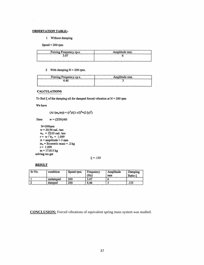
CONCLUSION: Forced vibrations of equivalent spring mass system was studied.
37
38


![Math19b Spring 2011 Midterm Review - Harvard … · Math19b Spring 2011 Midterm Review March 21, 2011 Tuesday, March 22, ... Ω lab A event B C Tuesday, March 22, ... A ] P [A ] k](https://static.fdocument.org/doc/165x107/5b8b0be17f8b9a49258c1922/math19b-spring-2011-midterm-review-harvard-math19b-spring-2011-midterm-review.jpg)


![Chapitre 12 : Propagation d’ondes · • Onde : vibration/perturbation qui se propage dans un milieu matériel Mexican wave ... [ondes de cisaillement] - vagues - vibration vibration](https://static.fdocument.org/doc/165x107/5b99783909d3f26e678c41a0/chapitre-12-propagation-d-onde-vibrationperturbation-qui-se-propage.jpg)