


γλώσσες
Σελίδες
Νομικός

1
WWW.VAF.NL
T-SenseOptical Torque Measuring Systems
_660Product Bulletin
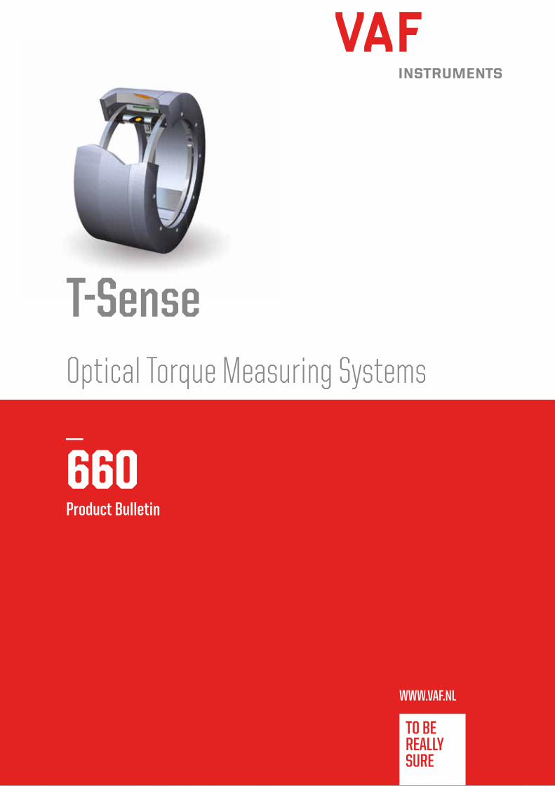
Power transmissionDetector arm
LED arm
Torque
detector
Δy is a small movement of the propeller shaft surface due to strain
Measuring principle
IntroductionThe use of a T-Sense torque measuring system means efficiency improvement,
overload protection and prevention of breakdown costs. For example in the
shipping industry its application has lead to savings up to 5% on fuel costs.
The system is based on extremely accurate optical sensor technology and can
be mounted around shafts in power transmission systems.
Why a torque measuring system?A torque meter provides you with precise information on engine performance
related to consumed energy. By giving instantaneous read-out of torque, speed
and power, the effects of operational changes are monitored. Because these
effects are measured, you can use your engine-driven installation in its most
efficient way. This will considerably reduce your fuel costs, one of the primary
cost drivers.
Where is the T-Sense torque measuring system used?T-Sense torque measuring systems are used for engine-driven installations in
all kinds of power and propulsion plants. For example continuous power output
measurement of ships propulsion, continuous power consumption measurement,
continuous level check for torque, speed and power and direct visual
control of changes in engine settings, trim and draught.
Possible system extensionsA full range of T-Sense torque measuring systems is available. The standard
output of the torque measuring system consists of a torque, shaft speed and
power signal. The system can be extended with energy consumption and
propeller shaft vibration analysis, or can be combined with fuel consumption
measurement.
Your advantageDesigned for durability and accuracyThe systems have a robust design. They are built to withstand the typical harsh
environmental conditions in ships, engine rooms, dredgers, steelworks and heavy
industries. Innovative optical sensor technology guarantees high accuracy with
an overall error of less than 0,5% F.S.D.
No maintenance requiredT-Sense torque measuring systems are maintenance-free as a result of
noncontact power and signal transmission. They are designed to work
continuously. No recalibration is needed, because signals are stable
during its lifetime.
Easy installation and commissioningThe intelligent design enables installation by customers staff.
Principle of operationThe T-Sense measuring system can be mounted on propeller or drive
shafts. When a shaft is subject to torque this will result in a small strain
at the shaft surface. A LED and an extremely accurate optical cell can
detect these small movements of the surface. The measured values are
transferred continuously from the rotating shaft to the stator part through
a 2.4 GHz wireless data connection. Power transmission from the stator to
the rotating shaft is performed by means of induction.
The stator part consists of a bracket, a power transmission coil, a data
signal receiver and a control box equipped with digital and analogue
output connections. These outputs can be linked directly to the vessels
data network, monitoring or control system.
The stator part can optionally be connected to a Propulsion Efficiency
Monitor (PEM2), which displays shaft power, torque and speed.
Optical displacement measurement
2
3
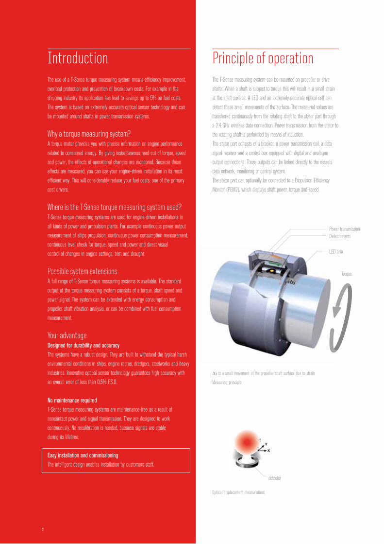
Typical system arrangement
2009
knots
/ sh
aft sp
eed
Efficiency monitoringTrip reportsCumulative valuesData storage
Fault detection
8x PT2 flow meter(flow + temp) for max. 4 consumers
Speed log/GPS
Typical T-Sense torque measuring system with optional
energy consumption and outputs
05 06 07
2007 2008
08 09 10 11 12 01 02 03 04 0505 06 07
2007
knots
/ sh
aft sp
ped
engin
e SF
OC2008
08 09 10 11 12 01 02 03 04 05
4
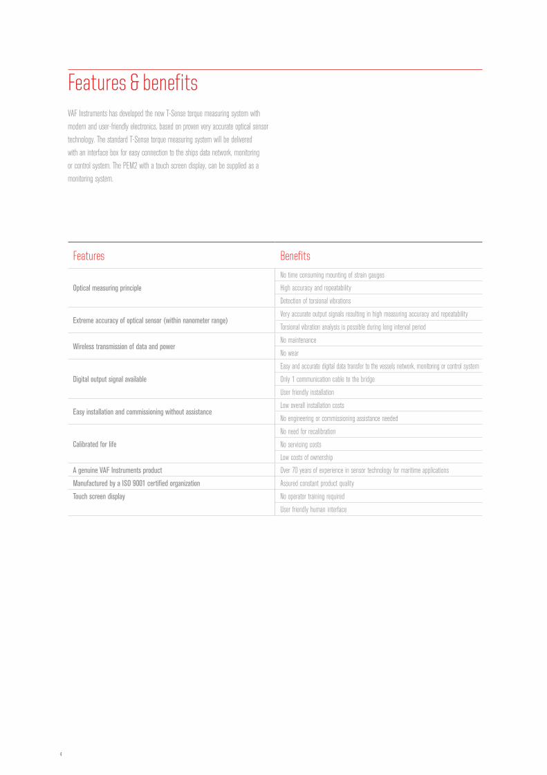
Features Benefits
Optical measuring principle
No time consuming mounting of strain gauges
High accuracy and repeatability
Detection of torsional vibrations
Extreme accuracy of optical sensor (within nanometer range)Very accurate output signals resulting in high measuring accuracy and repeatability
Torsional vibration analysis is possible during long interval period
Wireless transmission of data and powerNo maintenance
No wear
Digital output signal available
Easy and accurate digital data transfer to the vessels network, monitoring or control system
Only 1 communication cable to the bridge
User friendly installation
Easy installation and commissioning without assistanceLow overall installation costs
No engineering or commissioning assistance needed
Calibrated for life
No need for recalibration
No servicing costs
Low costs of ownership
A genuine VAF Instruments product Over 70 years of experience in sensor technology for maritime applications
Manufactured by a ISO 9001 certified organization Assured constant product quality
Touch screen display No operator training required
User friendly human interface
VAF Instruments has developed the new T-Sense torque measuring system with
modern and user-friendly electronics, based on proven very accurate optical sensor
technology. The standard T-Sense torque measuring system will be delivered
with an interface box for easy connection to the ships data network, monitoring
or control system. The PEM2 with a touch screen display, can be supplied as a
monitoring system.
Features & benefits
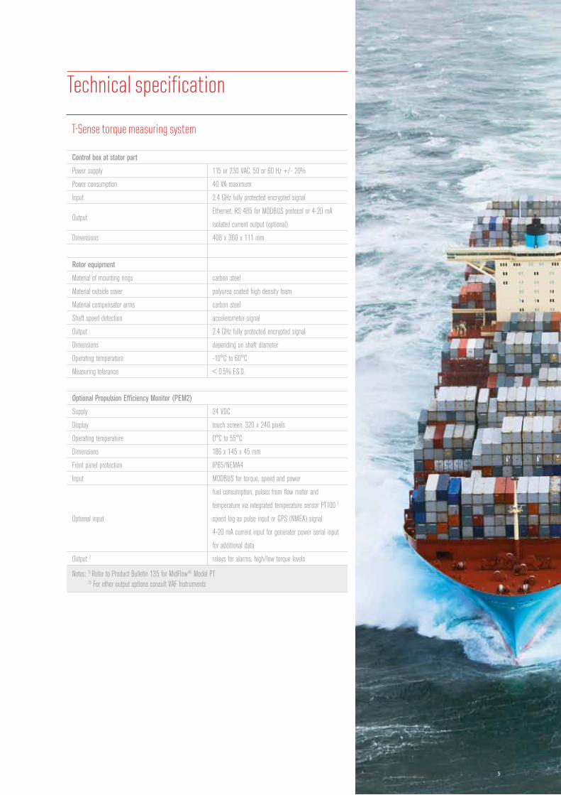
Control box at stator part
Power supply 115 or 230 VAC, 50 or 60 Hz +/- 20%
Power consumption 40 VA maximum
Input 2.4 GHz fully protected encrypted signal
OutputEthernet, RS 485 for MODBUS protocol or 4-20 mA
isolated current output (optional)
Dimensions 408 x 360 x 111 mm
Rotor equipment
Material of mounting rings carbon steel
Material outside cover polyurea coated high density foam
Material compensator arms carbon steel
Shaft speed detection accelerometer signal
Output 2.4 GHz fully protected encrypted signal
Dimensions depending on shaft diameter
Operating temperature -10°C to 60°C
Measuring tolerance < 0.5% F.S.D.
Optional Propulsion Efficiency Monitor (PEM2)
Supply 24 VDC
Display touch screen, 320 x 240 pixels
Operating temperature 0°C to 55°C
Dimensions 186 x 145 x 45 mm
Front panel protection IP65/NEMA4
Input MODBUS for torque, speed and power
Optional input
fuel consumption, pulses from flow meter and
temperature via integrated temperature sensor PT100 1
speed log as pulse input or GPS (NMEA) signal
4-20 mA current input for generator power serial input
for additional data
Output 2 relays for alarms, high/low torque levels
Notes: 1) Refer to Product Bulletin 135 for MidFlow® Model PT 2) For other output options consult VAF Instruments
Technical specification
T-Sense torque measuring system
5
6
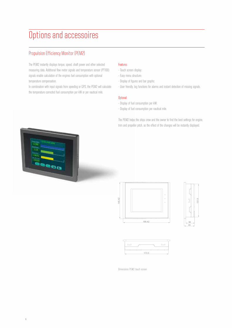
The PEM2 instantly displays torque, speed, shaft power and other selected
measuring data. Additional flow meter signals and temperature sensor (PT100)
signals enable calculation of the engines fuel consumption with optional
temperature compensation.
In combination with input signals from speedlog or GPS, the PEM2 will calculate
the temperature corrected fuel consumption per kW or per nautical mile.
Dimensions PEM2 touch screen
Features:
- Touch screen display;
- Easy menu structure;
- Display of figures and bar graphs;
- User friendly, log functions for alarms and instant detection of missing signals.
Optional:
- Display of fuel consumption per kW;
- Display of fuel consumption per nautical mile.
The PEM2 helps the ships crew and the owner to find the best settings for engine,
trim and propeller pitch, as the effect of the changes will be instantly displayed.
Options and accessoires
186.42
145.
42
173.5
3645
131.
5
cut out
174.5 ±0.5
132.
5 ±0
.5
Propulsion Efficiency Monitor (PEM2)
7
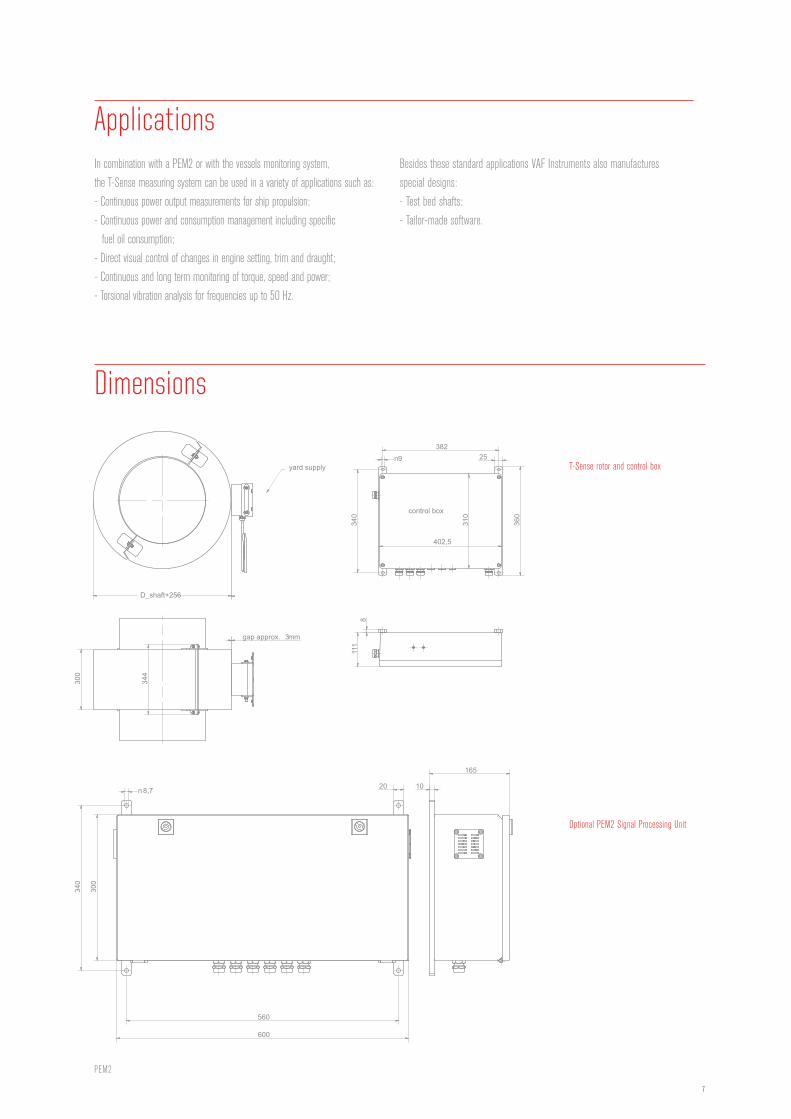
ApplicationsIn combination with a PEM2 or with the vessels monitoring system,
the T-Sense measuring system can be used in a variety of applications such as:
- Continuous power output measurements for ship propulsion;
- Continuous power and consumption management including specific
fuel oil consumption;
- Direct visual control of changes in engine setting, trim and draught;
- Continuous and long term monitoring of torque, speed and power;
- Torsional vibration analysis for frequencies up to 50 Hz.
control box
D_shaft+256
300
344
gap approx. 3mm
382
340
n9
8
25
360
111
402,5
310
yard supply
340
560
600
300
n 8,7 10
165
20
Dimensions
Besides these standard applications VAF Instruments also manufactures
special designs:
- Test bed shafts;
- Tailor-made software.
Optional PEM2 Signal Processing Unit
T-Sense rotor and control box
PEM2

8
1. Number of units per ship:
2. Ships name / hull:
3. Available shaft length [mm]:
4. Please provide shaft line drawing for installation:
new building retrofitting
5. Design conditions:
power [kW]:
speed [rpm]:
shaft material: shear modulus G [N/mm2]:
shaft diameter (+tolerance) [mm]:
inside diameter [mm]:
application propeller shaft dredge pump
jet pump other:
6. System:
required output torque range 4 - 20 mA = - kNm
RS 485/MODBUS
speed range 4 - 20 mA = - rpm
RS 485/MODBUS
power range 4 - 20 mA = - kW
RS 485/MODBUS
other:
options touch screen display for torque, shaft speed and power read-out
trip levels on torque
energy consumption
total power calculation for twin screw vessels
torsional vibration analysis
All c
opyr
ight
s re
serv
ed |
Pub
l No.
PB-6
60-G
B-05
12 |
Supe
rsed
es P
B-66
0-GB
-071
1
Quotation & ordering information
Represented by
Name:
Place and date:
For further information see relevant Product Bulletins or www.vaf.nl
VAF Instruments B.V.
Vierlinghstraat 24, 3316 EL Dordrecht, The Netherlands
P.O. Box 40, 3300 AA Dordrecht, The Netherlands
T +31 (0) 78 618 3100, F +31 (0) 78 617 7068
[email protected], www.vaf.nl
Specifications subject to change without notice.
Agents and distributors in more than 50 countries.
ISO 9001 REGISTERED
Top Related