WWER Pressure Vessel Life and Ageing Management for …€¦ · · 2007-11-07WWER Pressure Vessel...
50
Second International Symposium on Nuclear Power Plant Life Management, Shanghai, China, 15-18 October 2007 WWER Pressure Vessel Life and WWER Pressure Vessel Life and Ageing Management for NPP Long Ageing Management for NPP Long Term Operation in Russia. Term Operation in Russia. V. G. V. G. Vasiliev Vasiliev , , Yu.V Yu.V . . Kopiev Kopiev ROSENERGOATOM, RUSSIA
-
Upload
truongkhanh -
Category
Documents
-
view
217 -
download
2
Transcript of WWER Pressure Vessel Life and Ageing Management for …€¦ · · 2007-11-07WWER Pressure Vessel...
Second International Symposium on Nuclear Power Plant Life Management, Shanghai, China, 15-18 October 2007
WWER Pressure Vessel Life and WWER Pressure Vessel Life and Ageing Management for NPP Long Ageing Management for NPP Long
Term Operation in Russia.Term Operation in Russia.V. G. V. G. VasilievVasiliev, , Yu.VYu.V. . KopievKopiev
ROSENERGOATOM, RUSSIA
2
Contents•• LTO strategy in RussiaLTO strategy in Russia•• Regulatory basisRegulatory basis•• RPV integrity assessment guidelines RPV integrity assessment guidelines
improvementimprovement•• RPV ISI improvementRPV ISI improvement•• RPV radiation RPV radiation embrittlementembrittlement•• ConclusionsConclusions
3
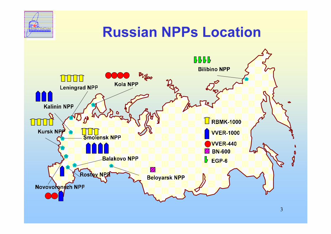
Russian NPPs Location
4
Long term operation (LTO) strategy1. “RF Nuclear power development program for the period 2007-2010 and for the period up to 2015”, approved by Government act № 605,06.10.2006
2. Strategy of Development of Nuclear Power Industry in the 1st Half of XXI Century
Both of the documents envisage provisions for :• Extension of operation life of operating NPPs• Adding new capacity by completion of units under
construction and building new units
5
Regulatory basis for LTO• Federal Law on the Use of Atomic Energy (Article 9)• General Provisions on Ensuring Safety of NPP(OPB-88/97), NP-001-97
(p.5.1.14)• Rules of NPP Equipment and Pipelines Layout and Safe operation, PNAE
G-7-008-89 (i 2.1.11)• Main Requirements for Operational Life Extension of NPP Power Unit, NP-
017-2000• Requirements for the Content and Composition of the Documents
Justifying The Safety for the Period of NPP Operational Life Extension, RD-04-31-2001
• The State Standard “Reliability of NPPs and their Equipment”• Guideline on Aging Management of NPP components RD-EO-0281-01• Set of the utility standards/guidelines on residual life-time assessment
and AMP programs for WWER mechanical components (vessels, pipelines, valves, pumps, etc.)
6
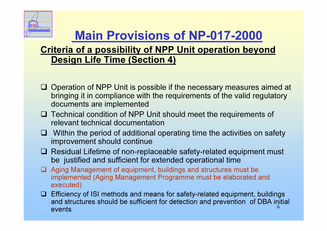
Main Provisions of NP-017-2000Criteria of a possibility of NPP Unit operation beyond Design Life Time (Section 4)
� Operation of NPP Unit is possible if the necessary measures aimed at bringing it in compliance with the requirements of the valid regulatory documents are implemented� Technical condition of NPP Unit should meet the requirements of
relevant technical documentation� Within the period of additional operating time the activities on safety
improvement should continue� Residual Lifetime of non-replaceable safety-related equipment must
be justified and sufficient for extended operational time� Aging Management of equipment, buildings and structures must be
implemented (Aging Management Programme must be elaborated and executed)� Efficiency of ISI methods and means for safety-related equipment, buildings
and structures should be sufficient for detection and prevention of DBA initial events
7
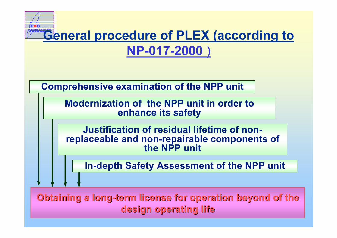
General procedure of PLEX (according to NP-017-2000 )
Obtaining a longObtaining a long--term license for operation beyond of the term license for operation beyond of the design operating lifedesign operating life
Comprehensive examination of the NPP unit
Justification of residual lifetime of non-replaceable and non-repairable components of the NPP unit
Modernization of the NPP unit in order to enhance its safety
In-depth Safety Assessment of the NPP unit
8
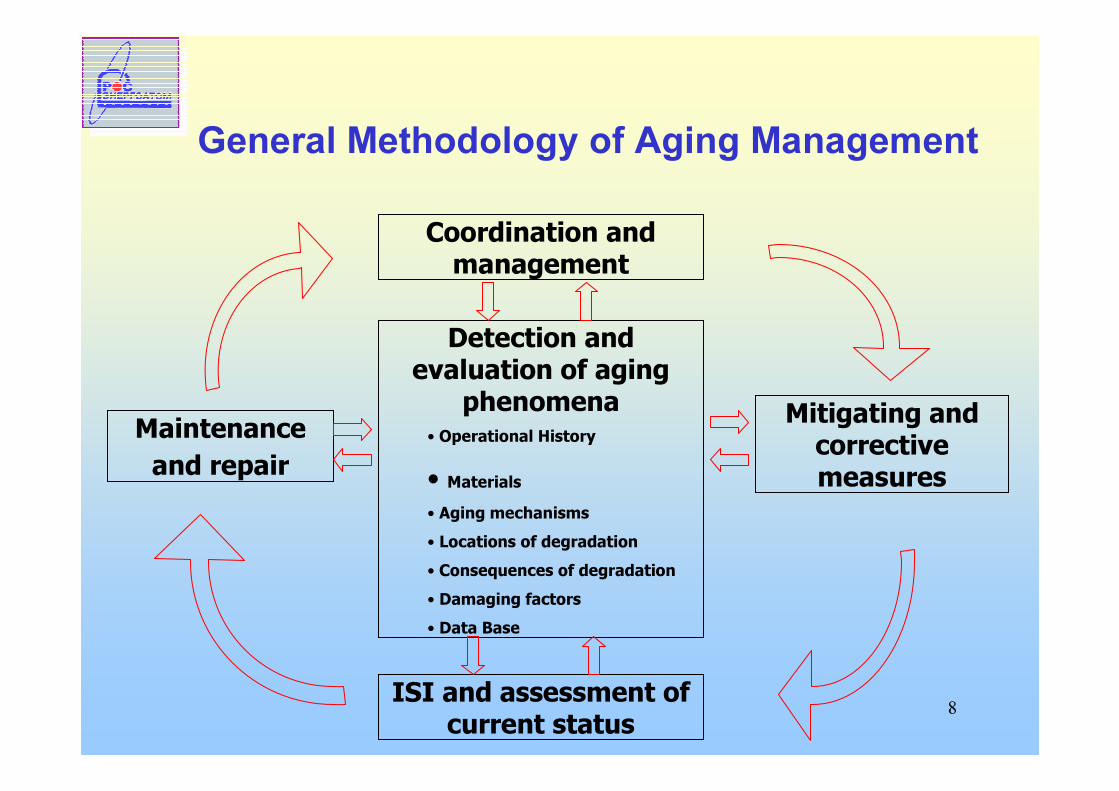
General Methodology of Aging Management
Detection and evaluation of aging
phenomena • Operational History
• Materials• Aging mechanisms• Locations of degradation • Consequences of degradation• Damaging factors• Data Base
ISI and assessment of current status
Coordination and management
Mitigating and corrective measures
Maintenance and repair
9
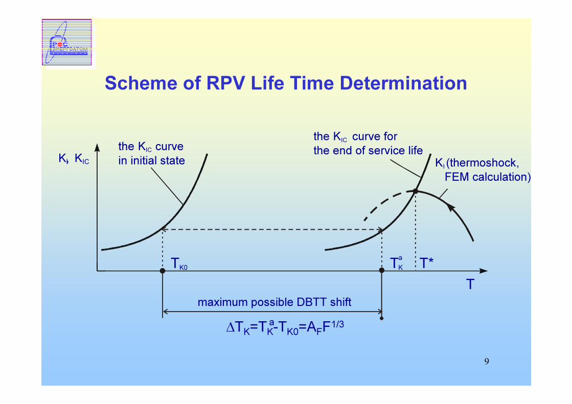
Scheme of RPV Life Time Determination
∆TK=TK-TK0=AFF1/3
K, I KIC K (thermoshock,FEM calculation)
I
the curve for the end of service life
KIC the K curve in initial state
IC
TK0 T*
maximum possible DBTT shiftT
TaK
a
10
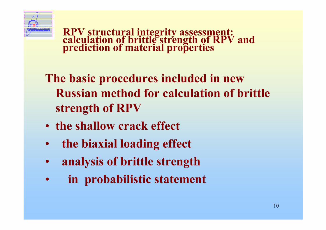
RPV structural integrity assessment:calculation of brittle strength of RPV and prediction of material properties
The basic procedures included in new Russian method for calculation of brittle strength of RPV
• the shallow crack effect • the biaxial loading effect• analysis of brittle strength• in probabilistic statement
11
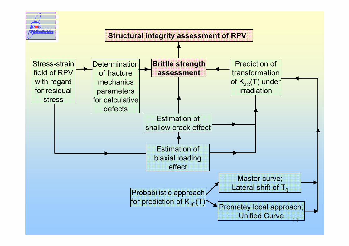
Structural integrity assessment of RPV
Stress-strain field of RPV with regard for residual
stress
Determination of fracture mechanics parameters for calculative
defects
Brittle strength assessment
Prediction of transformation of KJC(T) under irradiation
Estimation of shallow crack effect
Estimation of biaxial loading
effect
Probabilistic approach for prediction of KJC(T)
Master curve; Lateral shift of T0
Prometey local approach;Unified Curve
12
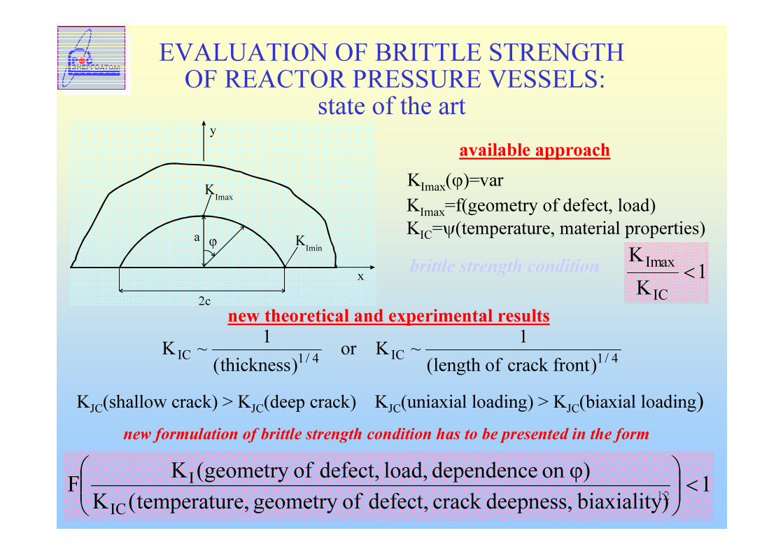
EVALUATION OF BRITTLE STRENGTHOF REACTOR PRESSURE VESSELS:
state of the artavailable approach
a ϕ
2c
y
x
KImax
KImin
KImax(ϕ)=varKImax=f(geometry of defect, load)KIC=ψ(temperature, material properties)brittle strength condition 1
KK
IC
axIm<
new theoretical and experimental results4/1IC4/1IC )frontcrackoflength(
1~Kor)thickness(1~K
KJC(shallow crack) > KJC(deep crack) KJC(uniaxial loading) > KJC(biaxial loading)new formulation of brittle strength condition has to be presented in the form
1)biaxiality deepness,crack defect, ofgeometry e,temperatur(K)on dependence load, defect, of geometry(KF
IC
I <
ϕ
13
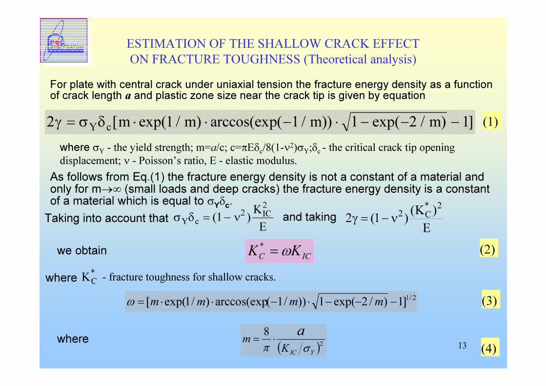
ESTIMATION OF THE SHALLOW CRACK EFFECT ON FRACTURE TOUGHNESS (Theoretical analysis)
For plate with central crack under uniaxial tension the fracture energy density as a function of crack length a and plastic zone size near the crack tip is given by equation
2 1 1 1 2 1γ σ δ= ⋅ ⋅ − ⋅ − − −Y c m m m m[ exp( / ) arccos(exp( / )) exp( / ) ] (1)where σY - the yield strength; m=a/c; c=πEδc/8(1-ν2)σY;δc - the critical crack tip opening displacement; ν - Poisson’s ratio, E - elastic modulus.
As follows from Eq.(1) the fracture energy density is not a constant of a material and only for m→∞ (small loads and deep cracks) the fracture energy density is a constant of a material which is equal to σYδc.
and taking E)K()1(22*
C2ν−=γ
we obtain *CK - fracture toughness for shallow cracks.
ICC KK ω=* (2)where
2/1]1)/2exp(1))/1(arccos(exp)/1exp([ −−−⋅−⋅⋅= mmmmω
σ δ νY cICKE= −( )1 22
Taking into account that
( )28
YICKm a
σπ⋅= (4)where
(3)
14
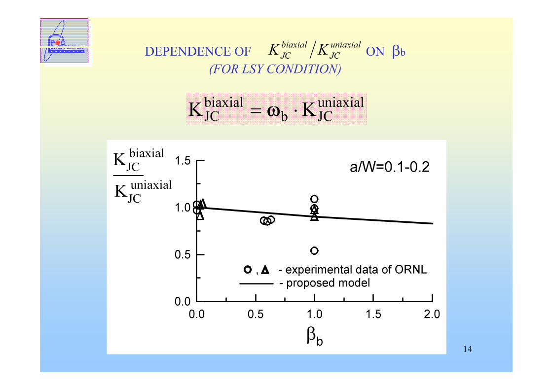
DEPENDENCE OF ON βb (FOR LSY CONDITION)
uniaxialJC
biaxialJC KK
0.0 0.5 1.0 1.5 2.0βb
0.0
0.5
1.0
1.5KJC biaxial
, - experimental data of ORNL - proposed model
a/W=0.1-0.2KJC uniaxial
uniaxialJCb
biaxialJC KK ⋅= ω
15
Loading biaxiality reduces fracture toughness for shallow cracks only, but at the same time fracture toughness for shallow crack higher than fracture toughness obtained on standard specimens.
In most cases if we take into account both shallow cracks effect and loading biaxiality we have fracture toughness higher than without regard for the above effects.
ICbC KK ωω=*
16
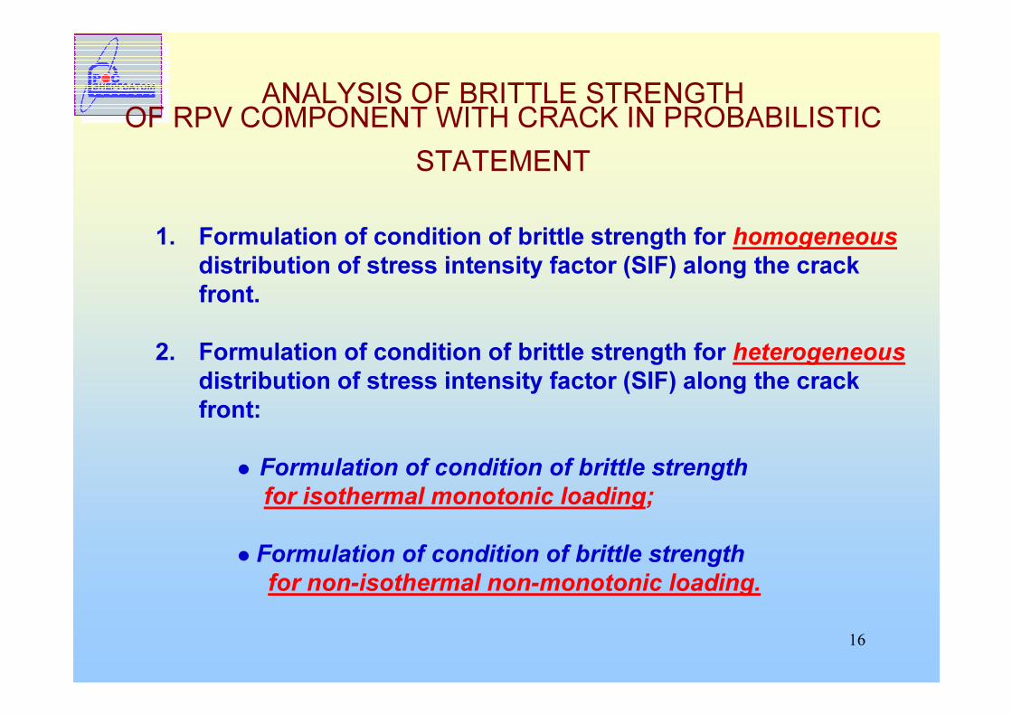
ANALYSIS OF BRITTLE STRENGTH OF RPV COMPONENT WITH CRACK IN PROBABILISTIC
STATEMENT
1. Formulation of condition of brittle strength for homogeneousdistribution of stress intensity factor (SIF) along the crack front.
2. Formulation of condition of brittle strength for heterogeneousdistribution of stress intensity factor (SIF) along the crack front:� Formulation of condition of brittle strength
for isothermal monotonic loading;� Formulation of condition of brittle strength
for non-isothermal non-monotonic loading.
17
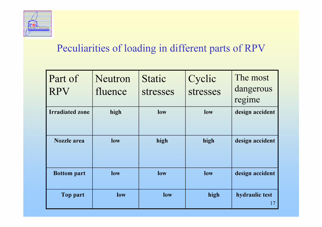
Peculiarities of loading in different parts of RPV
hydraulic testhighlowlowTop part
design accidentlowlowlowBottom part
design accidenthighhighlowNozzle area
design accidentlowlowhighIrradiated zone
The most dangerous regime
Cyclic stresses
Static stresses
Neutron fluence
Part ofRPV
18
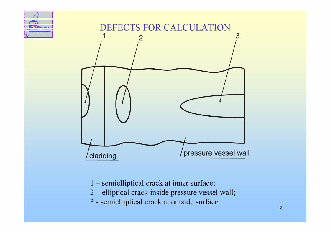
DEFECTS FOR CALCULATION
1 – semielliptical crack at inner surface; 2 – elliptical crack inside pressure vessel wall;3 - semielliptical crack at outside surface.
1 2 3
cladding pressure vessel wall
19
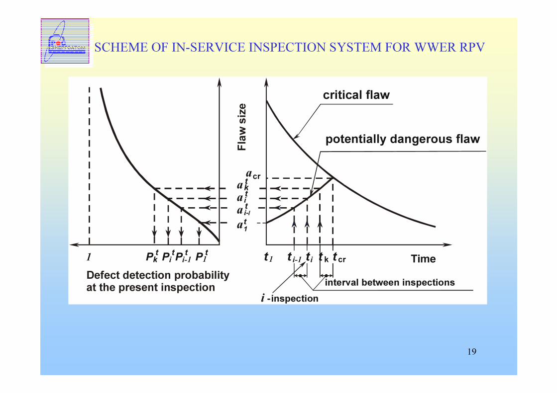
SCHEME OF IN-SERVICE INSPECTION SYSTEM FOR WWER RPV
a
interval between inspections
t i t kt1P11 t
i
Time
critical flaw
i - inspection
a i-1a1t
ak
ttt
PitPi-1t tPktFl
aw s
ize
a
t cr
potentially dangerous flaw
t i-1Defect detection probabilityat the present inspection
cr
20
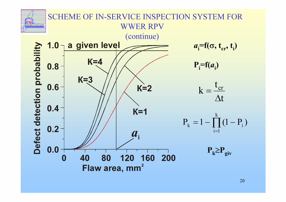
SCHEME OF IN-SERVICE INSPECTION SYSTEM FOR WWER RPV(continue)
К=1
К=2
К=4К=3
0 40 80 120 160 2000.00.2
0.4
0.6
0.8
1.0
Flaw area mm, 2
аi
a given level ai=f(σ, tcr, ti)
Pi=f(ai)
ttk cr
∆=
∏=
−−=k
1iik )P1(1P
Pk≥Pgiv
21
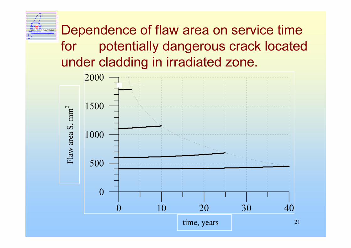
Dependence of flaw area on service time for potentially dangerous crack locatedunder cladding in irradiated zone.
0 10 20 30 400
500
1000
1500
2000Fla
w are
a S, m
m2
time, years
22
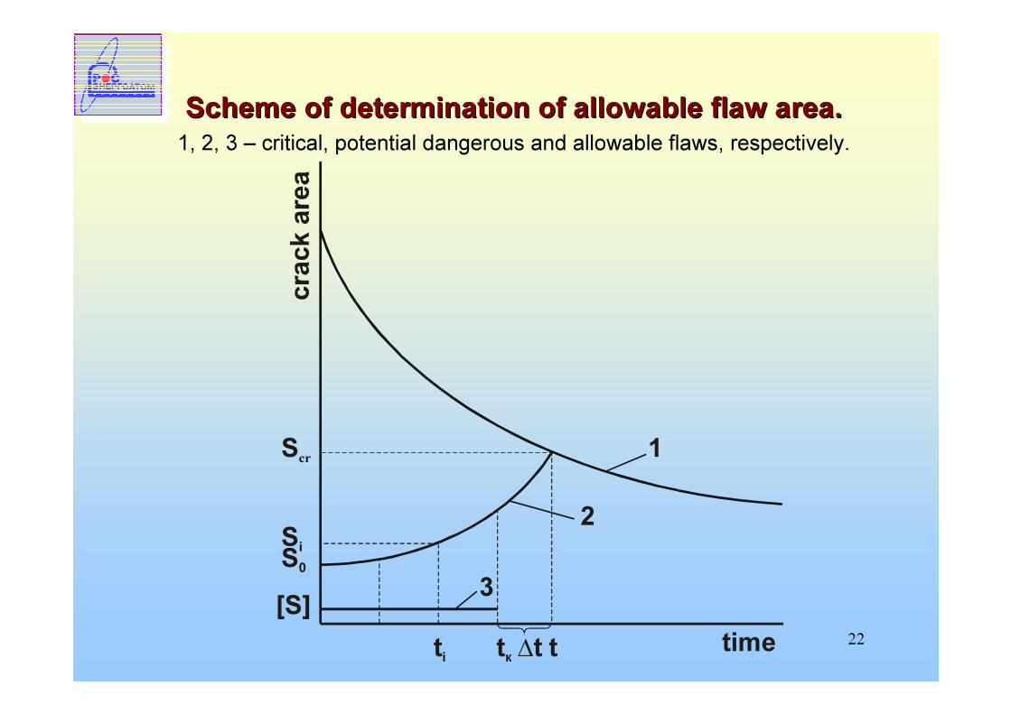
Scheme of determination of allowable flaw area.Scheme of determination of allowable flaw area.1, 2, 3 – critical, potential dangerous and allowable flaws, respectively.
S0
[S]
2
1
3Si
Scr
ti tк ∆t t time
23
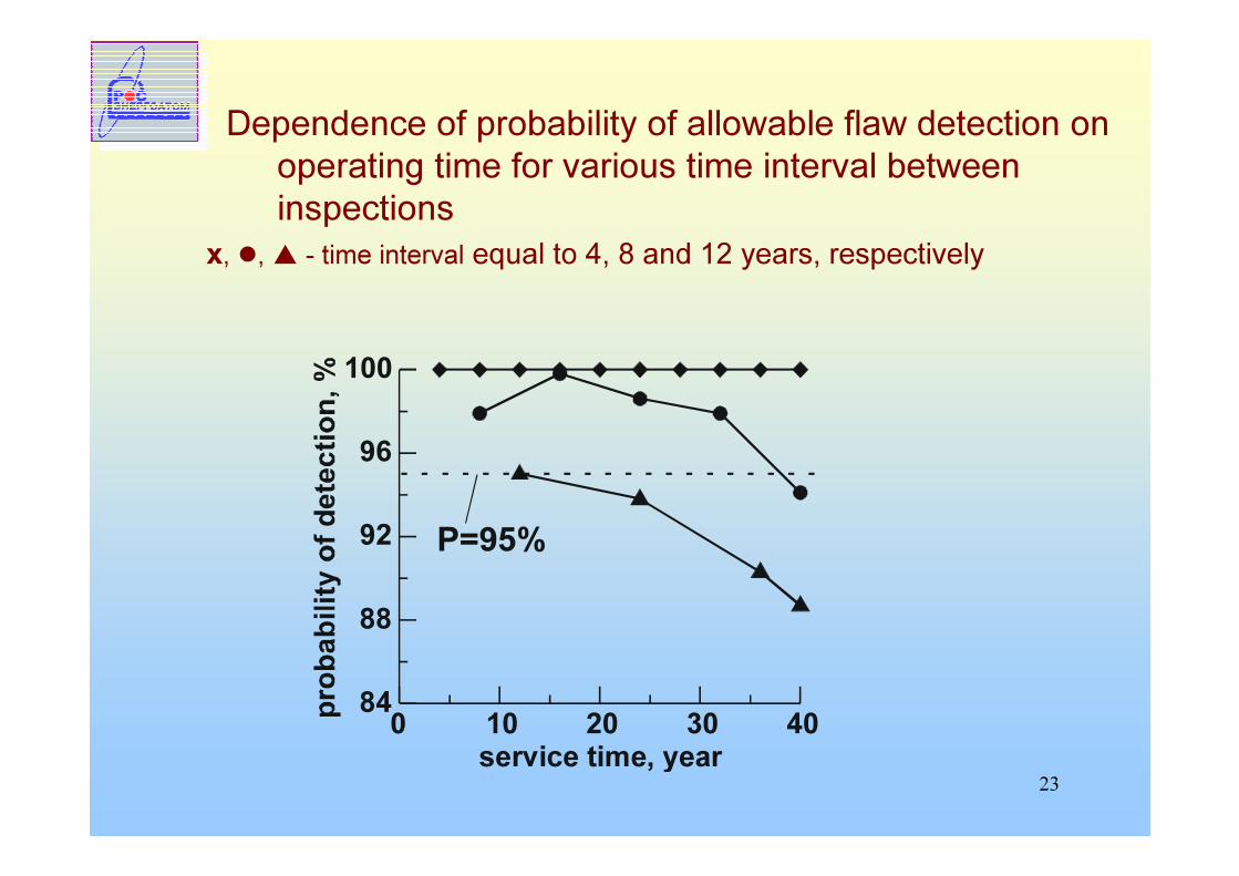
Dependence of probability of allowable flaw detection onoperating time for various time interval between inspections
x, �, � - time interval equal to 4, 8 and 12 years, respectively
0 10 20 30 40s t yearervice ime,
84
88
92
96
100
P=95%
24
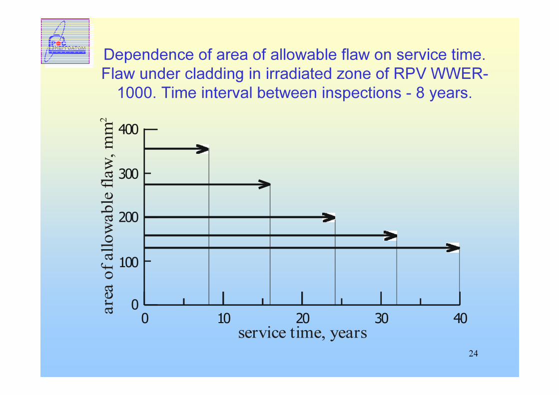
Dependence of area of allowable flaw on service time. Flaw under cladding in irradiated zone of RPV WWER-1000. Time interval between inspections - 8 years.
0 10 20 30 400
200
400
300
100
service time, years
area
of al
lowab
le fla
w, m
m2
25
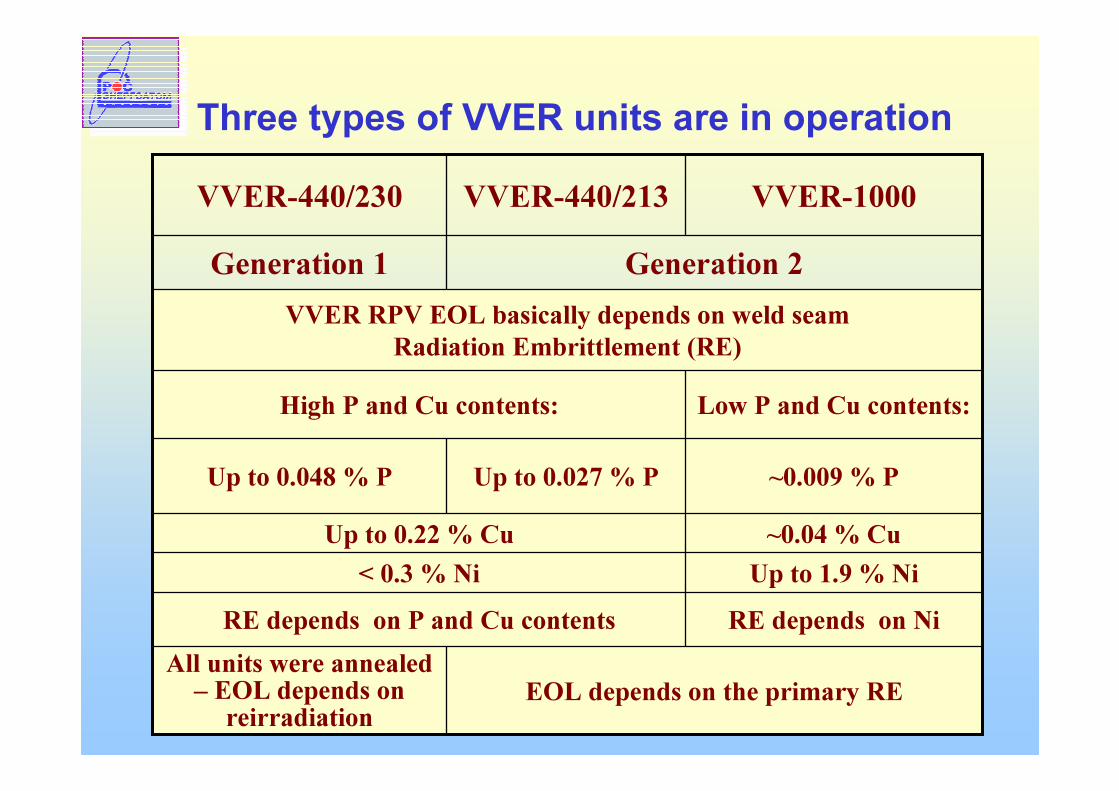
Three types of VVER units are in operation
VVER RPV EOL basically depends on weld seam Radiation Embrittlement (RE)
Low P and Cu contents:High P and Cu contents:
Generation 2Generation 1
~0.04 % CuUp to 0.22 % CuUp to 0.027 % P
Up to 1.9 % Ni< 0.3 % Ni
EOL depends on the primary REAll units were annealed
– EOL depends on reirradiation
RE depends on NiRE depends on P and Cu contents
~0.009 % PUp to 0.048 % P
VVER-1000 VVER-440/213 VVER-440/230
26
Procedure of the determination of RPV material Procedure of the determination of RPV material irradiation lifetimeirradiation lifetime
Obtaining the representative experimental results for providing forecast of material properties changesDevelopment of the material irradiation embrittlement modelConfirmation of the material irradiation embrittlement model conservatism accepted for the calculationsIndividual calculation curves on base of the RPV metal tests
27
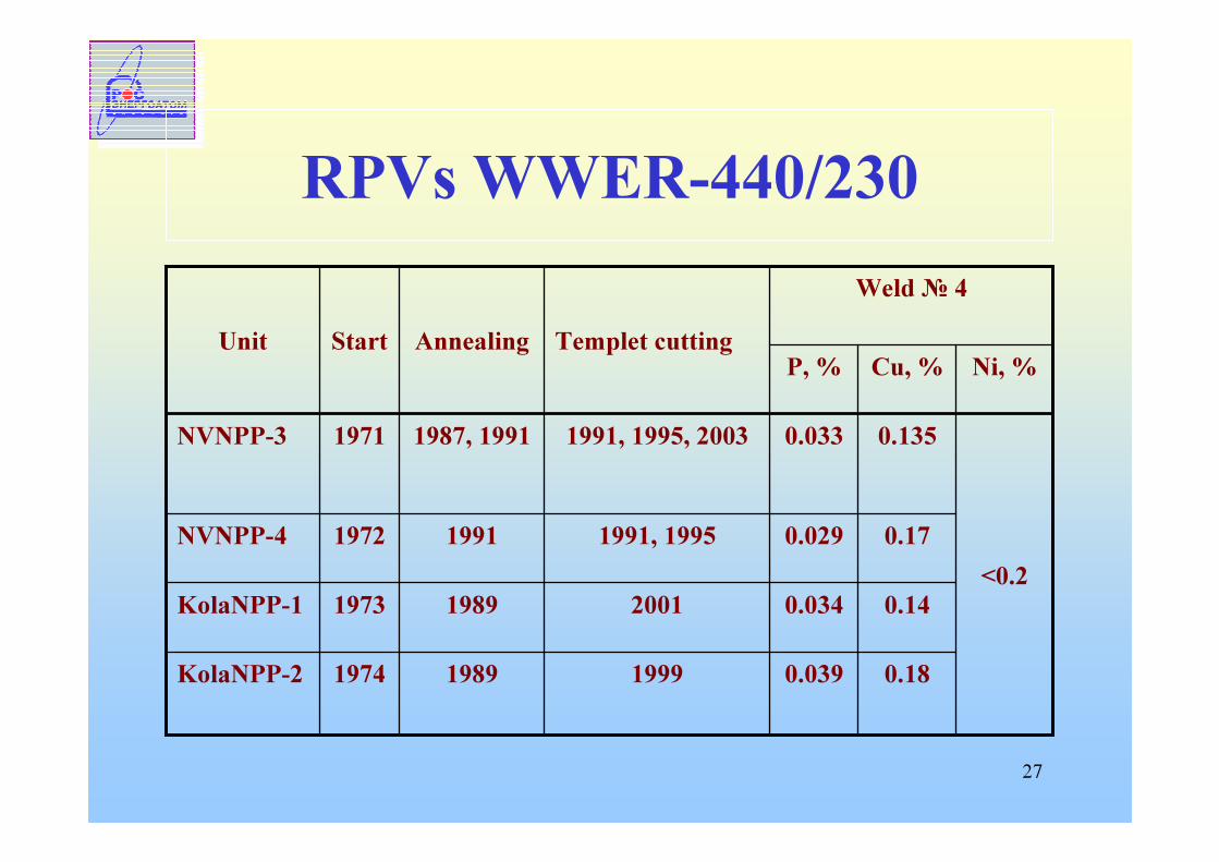
RPVs WWER-440/230
0.180.039199919891974KolaNPP-2
0.140.034200119891973KolaNPP-1
0.170.0291991, 199519911972NVNPP-4<0.2
0.1350.0331991, 1995, 20031987, 19911971NVNPP-3
Ni, %Cu, %P, %
Weld № 4Templet cuttingAnnealingStartUnit
28
� Absence of ТК0, СР, СCU data for RPV materials situated in core region
� Absence of surveillance specimens programs� First SS results from other NPPs showed high level of
radiation embrittlement for welds #4 materials doing impossible to operate up to end of design lifetime
� Annealing of welds #4 – recovering of properties� Putting of demy assemblies in core – reducing of radiation
loading of RPVwall� Determination of re-irradiation after annealing behavior of
WWER-440 weld materials
29
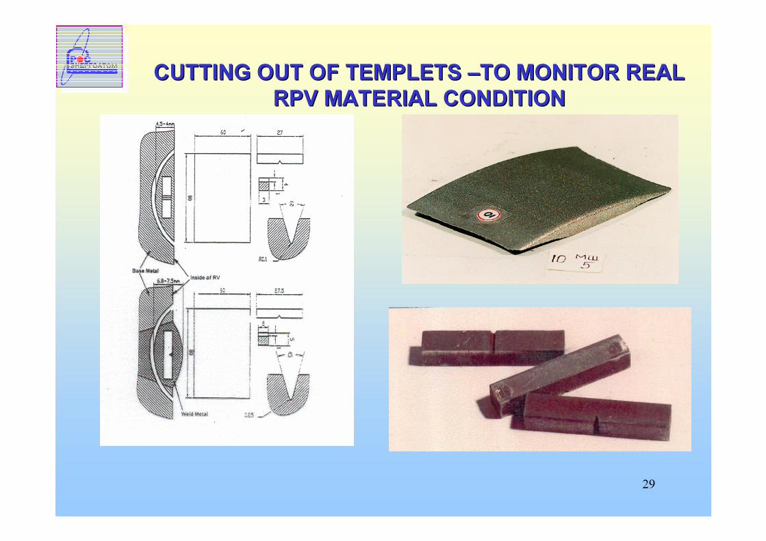
CUTTING OUT OF TEMPLETS CUTTING OUT OF TEMPLETS ––TO MONITOR REAL TO MONITOR REAL RPV MATERIAL CONDITIONRPV MATERIAL CONDITION
30
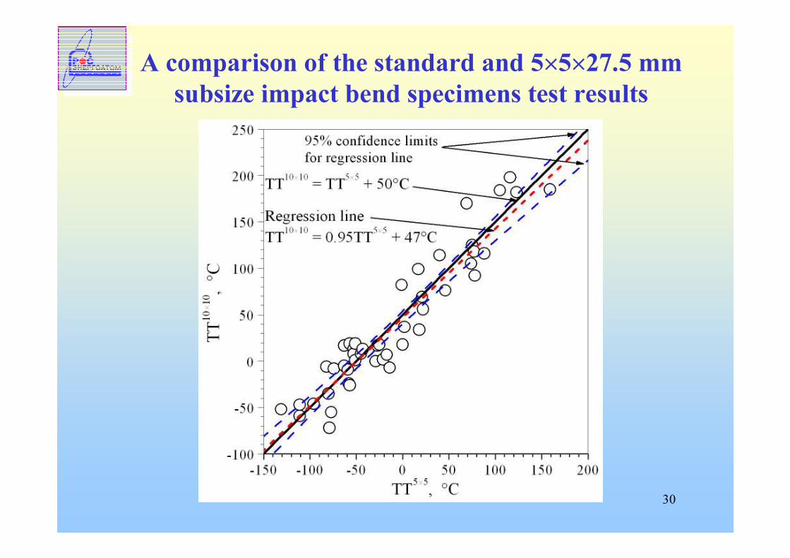
A comparison of the standard and 5×5×27.5 mmsubsize impact bend specimens test results
31
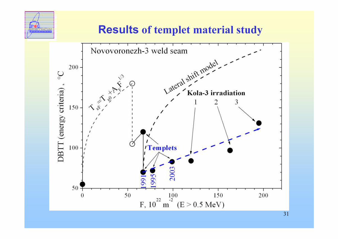
Results of templet material study
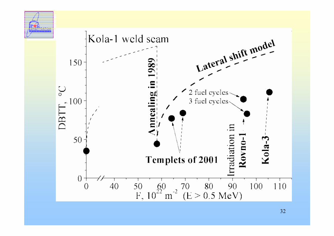
32
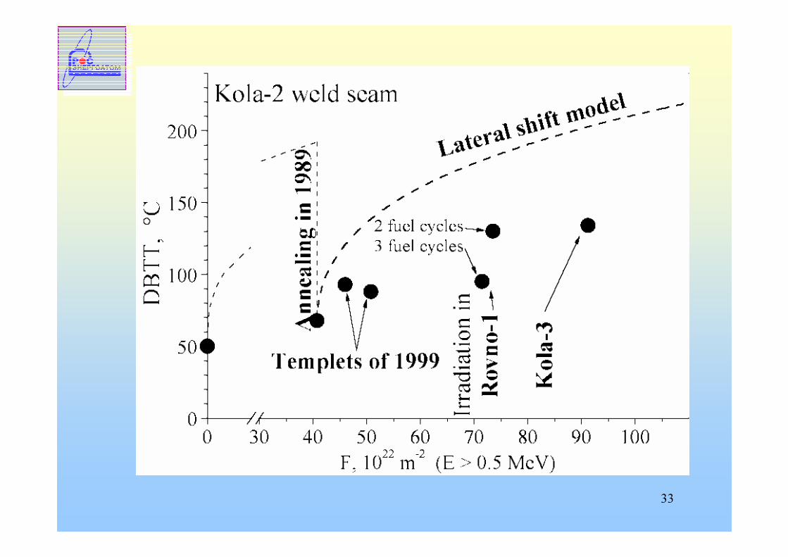
33
34
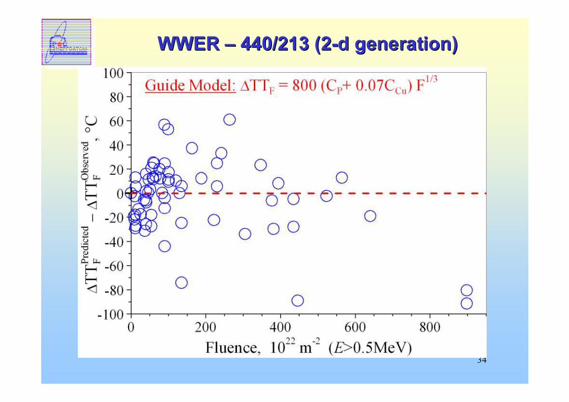
WWER WWER –– 440/213 (2440/213 (2--d generation)d generation)
35
WWER WWER –– 440/213 (2440/213 (2--d generation)d generation)- Elaborating of new model for radiation embrittlement of RPV materials taking into account possible flux effect
-Application of subsize specimens for study of radiation embrittlement of RPV steels of each WWER-440 Unit of NPP provide an individual prognosis for possible lifetime extension
-A new less conservative model of VVER-440 RPV steels radiation embrittlement can be developed using surveillance data from the top containers
36
WWER-1000 RPVs� Low P and Cu contents� High Ni content in weld metal (Up to 1.9 %)� EOL depends on the primary Radiation
Embrittlement� Elaborating of RE dependence is based on
SS and research results
37
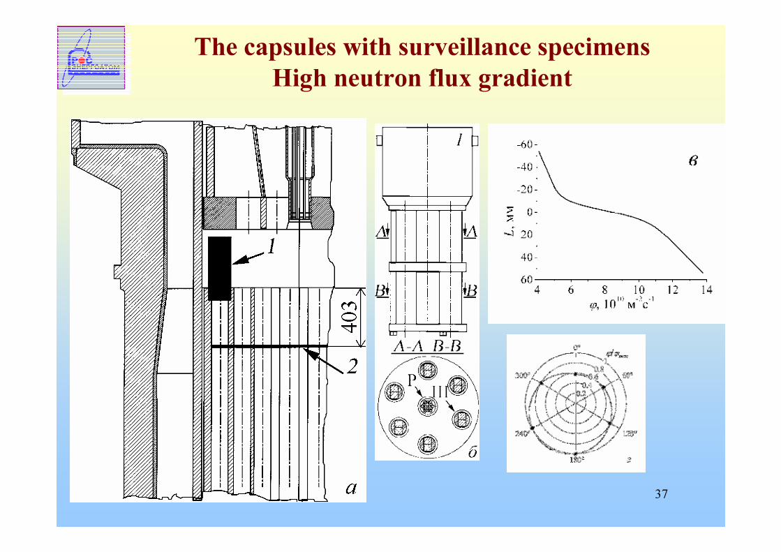
The capsules with surveillance specimens High neutron flux gradient
38
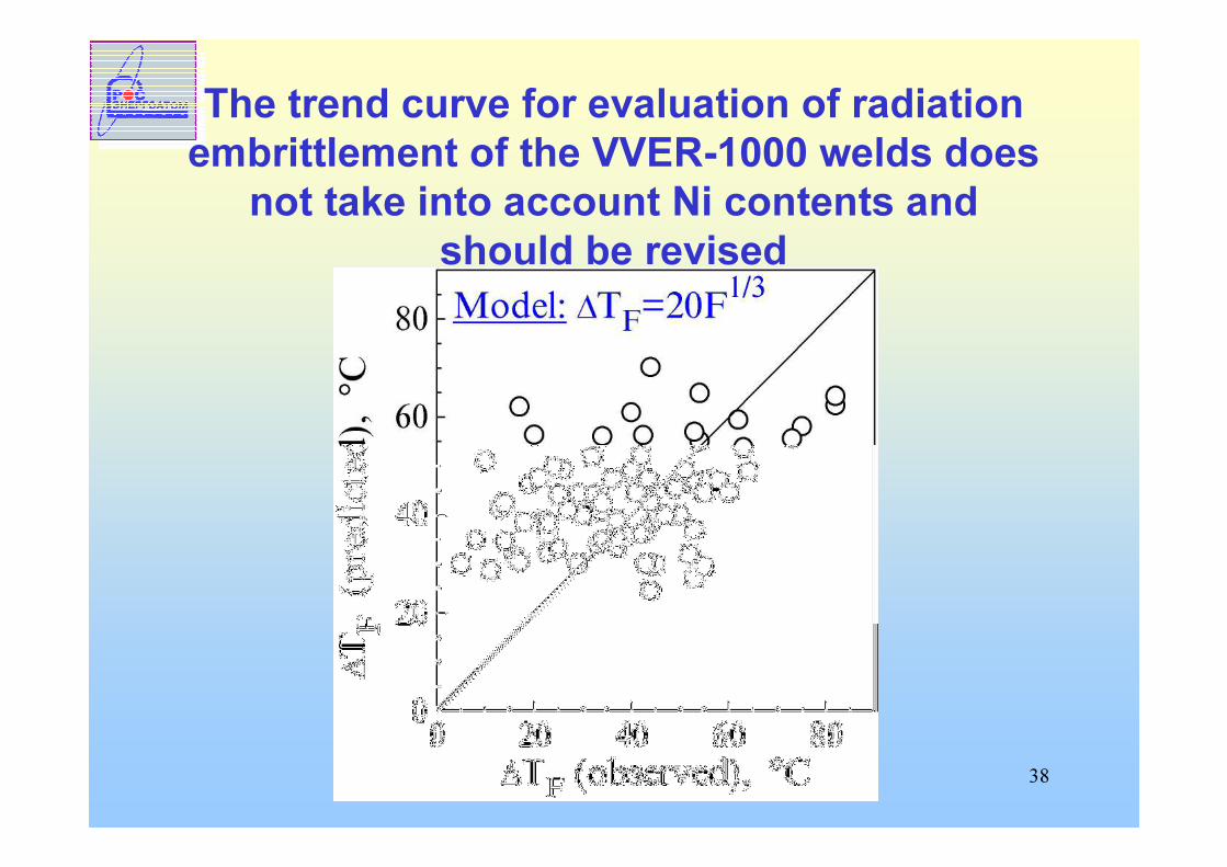
The trend curve for evaluation of radiation embrittlement of the VVER-1000 welds does
not take into account Ni contents and should be revised
39
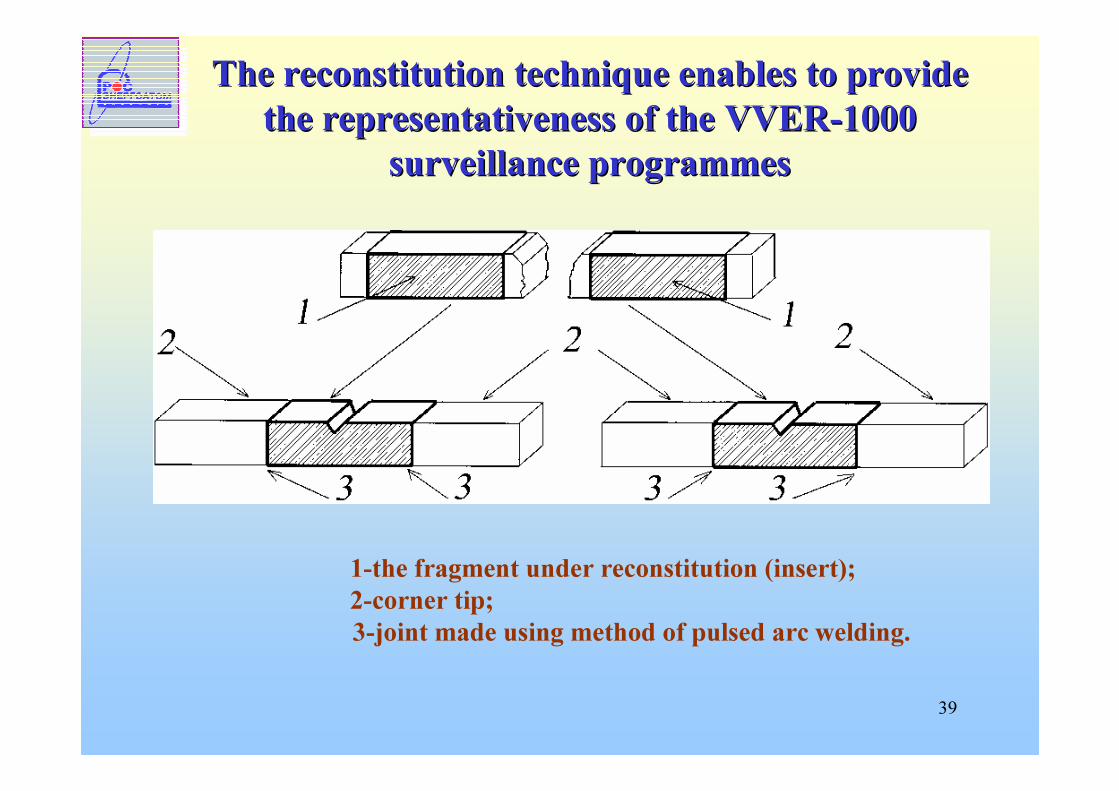
The reconstitution technique enables to provide The reconstitution technique enables to provide the the representativenessrepresentativeness of theof the VVERVVER--1000 1000
surveillance programmessurveillance programmes
1-the fragment under reconstitution (insert); 2-corner tip; 3-joint made using method of pulsed arc welding.
40
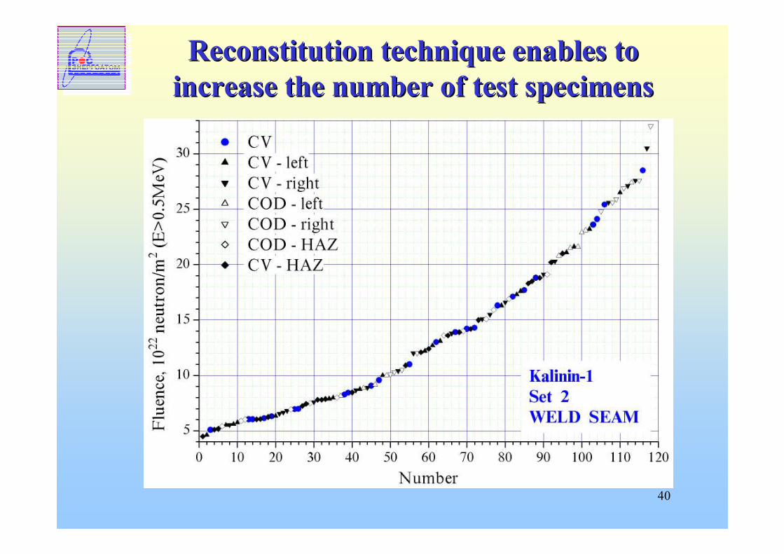
Reconstitution technique enables to Reconstitution technique enables to increase the number of test specimensincrease the number of test specimens
41
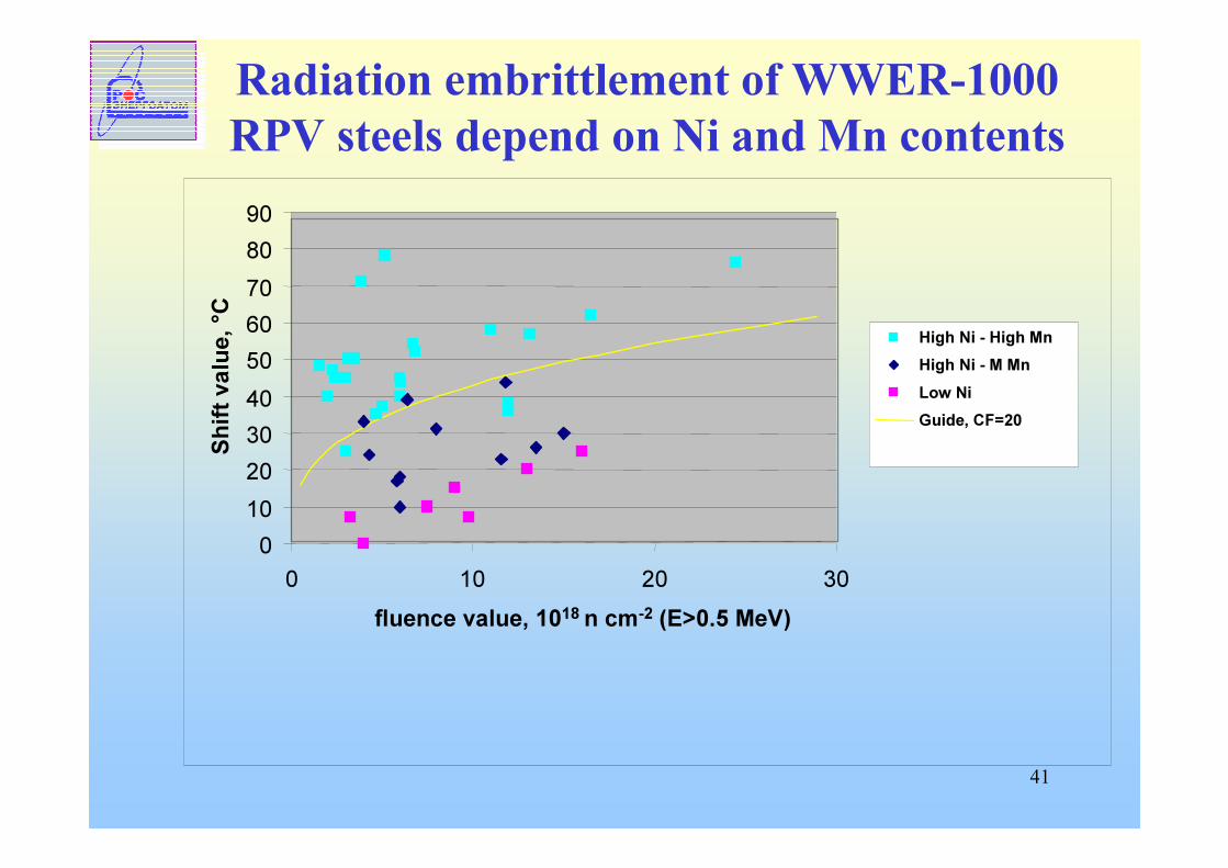
Radiation embrittlement of WWER-1000RPV steels depend on Ni and Mn contents
0102030405060708090
0 10 20 30fluence value, 1018 n cm-2 (E>0.5 MeV)
Shift
value
, °C
High Ni - High MnHigh Ni - M MnLow NiGuide, CF=20
42
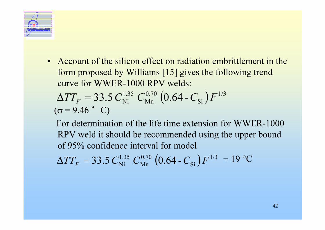
• Account of the silicon effect on radiation embrittlement in the form proposed by Williams [15] gives the following trend curve for WWER-1000 RPV welds:
(σ = 9.46 °C)For determination of the life time extension for WWER-1000 RPV weld it should be recommended using the upper bound of 95% confidence interval for model
+ 19 °C
( ) 1/3Si
0.70Mn
1.35Ni -0.64 5.33∆ FCCCTTF =
( ) 1/3Si
0.70Mn
1.35Ni -0.64 5.33∆ FCCCTTF =

43
RPV surveillance RPV surveillance programmeprogramme•• Further improvement of surveillance Further improvement of surveillance
programmeprogramme practices and corresponding practices and corresponding standards is neededstandards is needed–– Procedures for direct measurement of Procedures for direct measurement of
fracture toughness (Masterfracture toughness (Master--Curve, Local Curve, Local approach) approach)
•• Standardized procedure for Standardized procedure for implementation of surveillance results in implementation of surveillance results in RPV integrity and lifetime assessment is RPV integrity and lifetime assessment is needed.needed.
44
Current activitiesCurrent activities• Programme for elaboration of regulatory basis for
surveillance results implementation in WWER-1000 RPV integrity and lifetime assessment (approved by Rosenrgoatom in 2006)– Prediction of reference fracture toughness curve on the
base of surveillance results, including specification of necessary safety margins to address:• Non-uniformity of material properties within shells and
welds• Limited number of specimens
– Elaboration of detailed guidelines for surveillance specimens testing• number of specimens, sequence and methodology of
testing• addressing unit specific features of surveillance
programme
45
R&D activities related to PLIMProject TAREG 2.01/2000 (joint project for Russia and Ukraine) Validation of neutron /embrittlement for VVER 1000&440/213 RPVs, with emphasis on integrity assessment
– Reassessment and enlargement of the data base on surveillance results
– Validation of the procedures for direct fracture toughness measurement
– RPV WWER-1000 and WWER-440/B-213 integrity assessment
46
R&D activities related to PLIM (2)
Project TAREG2.01/03. Neutron irradiation embrittlement assessment and validation of embrittlement models for VVER Reactor Pressure Vessels (Regional Project Russia/Ukraine)
– The twin project to TAREG 2.01/00 (initially planed as TAREG 2.02/00)
47
General structure of the Project TAREG2.01/03
• Task 1: Project preparation• Task 2: Qualification of the reconstitution technique• Task 3: Reconstitution and testing of VVER-1000 RPV
specimens• Task 4: Reconstitution and testing of VVER-440/213 RPV
specimens• Task 5: Experimental tests and analysis to compare
different embrittlement assessment methodologies• Task 6: Investigations regarding cladding metal properties• Task 7: Summary Workshop • Task 8: Final Report
48
CONCLUSIONS1. New method of evaluation of brittle strength of RPV takes into account.� technology of manufacturing of RPV:- residual weld stresses and their variation depending on
the tempering duration;- possible maximum sizes of flaws;� in-service non-destructive testing results:- the type of the calculated defects – surface or
undercladding;� advance tendencies in fracture mechanics:- the crack front length effect on fracture toughness;- the effect of biaxial loading, typical for RPV, on fracture
toughness;- the shallow crack effect on fracture toughness.
49
CONCLUSIONS (cont.)2. New method allows one to increase the adequacy of estimation of brittle strength of RPV and, on the other hand, to decrease conservatism when predicting the RPV service life.
3 New concept of ISI system provides increasing time interval between RPV inspections from 4 to 8 years.4 Development of a new, physically proved model for re-irradiation embrittlement of WWER-440/230 RPV materials will allow validation of NPP lifetime extension for about 15 – 20 years beyond the design operation period for power units of the first generation.5 The standard reference dependences used at present for prediction of radiation embrittlement of WWER-440/213 and WWER-1000 RPV materials should be updated for LTO (60 years) taking into account surveillance programs data and fast neutron flux influence.

50
THANK YOU