Valery Telnov Budker INP, Novosibirsk LCWS 2012, Arlington, US, October 24, 2012 View on photon...
54
Valery Telnov Budker INP, Novosibirsk LCWS 2012, Arlington, US, October 24, 2012 View on photon colliders ILC, CLIC, Higgs factory SAPPHI and super γγ factory
-
Upload
elmer-manning -
Category
Documents
-
view
223 -
download
0
Transcript of Valery Telnov Budker INP, Novosibirsk LCWS 2012, Arlington, US, October 24, 2012 View on photon...
Valery TelnovBudker INP, Novosibirsk
LCWS 2012, Arlington, US, October 24, 2012
View on photon colliders at ILC, CLIC, Higgs factory SAPPHIRE
and super γγ factory

Oct. 24, 2012, LCWS 2012 Valery Telnov2
Contents
IntroductionILCCLICSAPPHIRESuper γγ factoryConclusion

Oct. 24, 2012, LCWS 2012 Valery Telnov3
Hi Valery,By the way, recently some DESY colleagues told me that a few years ago there had been a study on the physics case for a gamma-gamma collider, led by former KEK director Sugawara san, and the result of this study was that there is no physics case. According to these sources even you have agreed that there is no physics case for a gamma-gamma collider. Is this correct? Best regards Xxxxxxxxxx
Introduction

Oct. 24, 2012, LCWS 2012 Valery Telnov4
The answer Indeed, in 2008 H. Sugawara suggested to build γγ collider for the Higgs study on the energy 2E=160 GeV, as a precursor to the e+e- ILC, because it is cheaper (lower energy, no DR). The ILCSC asked my opinion. It was (shortly) the following:Such PLC will be not much cheaper, because needs DR and laser system. The Higgs decay modes, even invisible, can be studied much better in e+e→ZH at 2E~230 GeV due to lower physics backgrounds. This opinion was confirmed by physics and accelerator groups, followed by corresponding ILCSC statement … A 180 GeV gamma-gamma precursor would cost about half that of the 500 GeV ILC, but would produce much less physics. A better alternative for early Higgs studies would be a ~ 230 GeV e+e- collider for studying the Higgs through ZH production; this would be ~ 30% more costly than the gamma-gamma collider. ILCSC decided not to pursue the gamma-gamma collider further at this time. So, ILCSC has not supported PLC as precursor to the ILC, but not PLC in general. PLC is very natural and cheap addition to any LC, has very rich physics program complementary to e+e- collider.
Oct. 24, 2012, LCWS 2012 Valery Telnov5
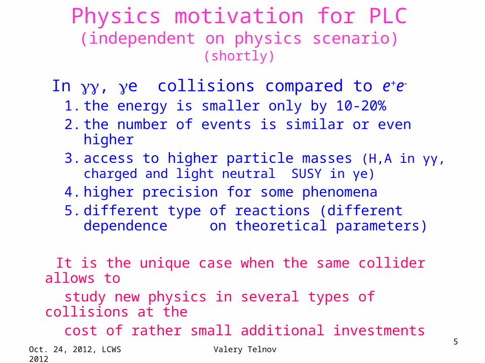
Physics motivation for PLC(independent on physics scenario)
(shortly)
In , e collisions compared to e+e-
1. the energy is smaller only by 10-20%2. the number of events is similar or even higher3. access to higher particle masses (H,A in γγ, charged
and light neutral SUSY in γe) 4. higher precision for some phenomena5. different type of reactions (different dependence
on theoretical parameters)
It is the unique case when the same collider allows to study new physics in several types of collisions at the cost of rather small additional investments

Oct. 24, 2012, LCWS 2012 Valery Telnov6
Photon collider at ILC
Oct. 24, 2012, LCWS 2012 Valery Telnov7
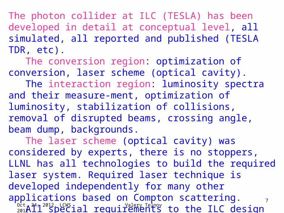
The photon collider at ILC (TESLA) has been developed in detail at conceptual level, all simulated, all reported and published (TESLA TDR, etc). The conversion region: optimization of conversion, laser scheme (optical cavity). The interaction region: luminosity spectra and their measure-ment, optimization of luminosity, stabilization of collisions, removal of disrupted beams, crossing angle, beam dump, backgrounds. The laser scheme (optical cavity) was considered by experts, there is no stoppers, LLNL has all technologies to build the required laser system. Required laser technique is developed independently for many other applications based on Compton scattering. All special requirements to the ILC design have been formulated and reported to the GDE. Further developments need political decisions and finances.
Oct. 24, 2012, LCWS 2012 Valery Telnov8
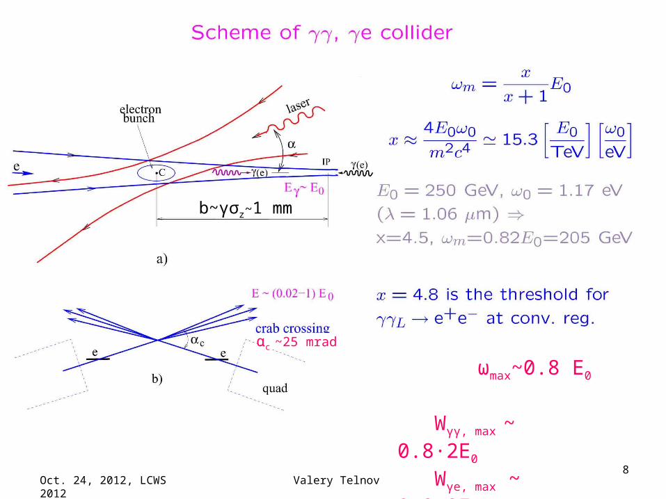
αc ~25 mrad
ωmax~0.8 E0
Wγγ, max ~ 0.8·2E0
Wγe, max ~ 0.9·2E0
b~γσz~1 mm

Oct. 24, 2012, LCWS 2012 Valery Telnov9
Realistic luminosity spectra ( and e)(with account multiple Compton scattering, beamstrahlung photons
and beam-beam collision effects)
For γe it is better to convert only one electron beam, in this case it will be easier to identify γe reactions, to measure its luminosity (and polarization)
and the γe luminosity will be larger.
(decomposed in two states of Jz)
Usually a luminosity at the photon collider is defined as the luminosityin the high energy peak, z>0.8zm.
Lγγ(z>0.8zm) ~(0.17-0.55) Le+e-(nom)
~ (0.35-1) ∙1034 cm-2 s-1
For ILC conditions
First number - nominal beam emittancesSecond - optimistic emittances
(possible, needs optimization of DR for γγ)
(but cross sections in γγ are larger by one order!)
(ILC)

Oct. 24, 2012, LCWS 2012 Valery Telnov10
Properties of the beams after CP,IP
zE /1
Electrons:
Emin~6 GeV,θx max~8 mradθy max~10 mrad
practically same for E0=100 and 250 GeV
An additional vertical deflection, about ±4 mrad, adds the detector field
For low energy particles the deflection in the field of opposing beam
αc= (5/400) (quad) + 12.5 ·10-3(beam) ~ 25 mrad

Oct. 24, 2012, LCWS 2012 Valery Telnov11
Crab-crossing angle
Crossing angle is determined by the angular spread in the disrupted beam and the radius of the first quad
αc~25 mrad
Oct. 24, 2012, LCWS 2012 Valery Telnov12
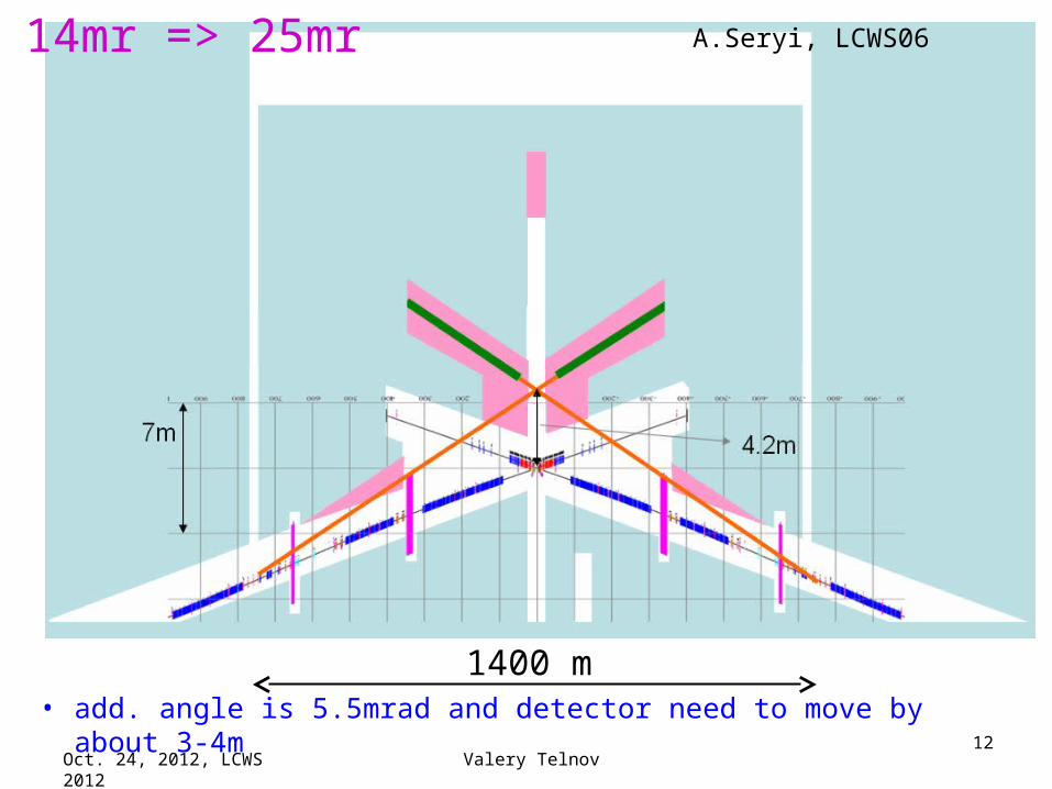
14mr => 25mr
• add. angle is 5.5mrad and detector need to move by about 3-4m
A.Seryi, LCWS06
1400 m
Oct. 24, 2012, LCWS 2012 Valery Telnov13
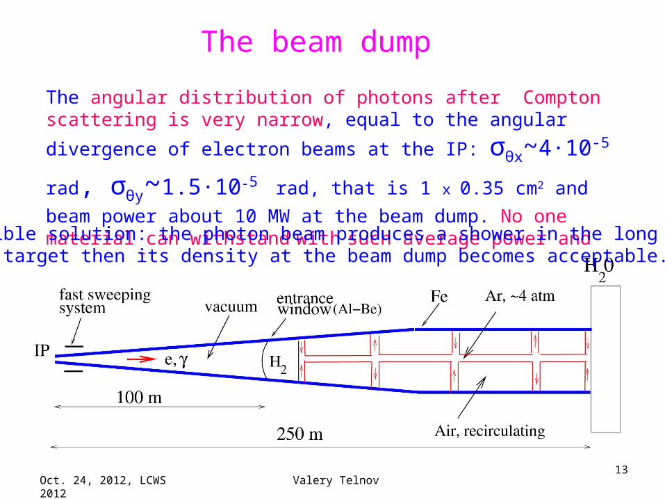
The angular distribution of photons after Compton scattering is very narrow, equal to the angular divergence of electron beams at the IP:
σθx~4·10-5 rad, σθy~1.5·10-5 rad, that is 1 x 0.35 cm2 and beam power
about 10 MW at the beam dump. No one material can withstand with
such average power and energy of one ILC train.
The beam dump
Possible solution: the photon beam produces a shower in the long gas (Ar) target then its density at the beam dump becomes acceptable.
Oct. 24, 2012, LCWS 2012 Valery Telnov14
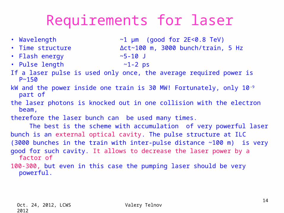
Requirements for laser• Wavelength ~1 μm (good for 2E<0.8 TeV)• Time structure Δct~100 m, 3000 bunch/train, 5 Hz• Flash energy ~5-10 J• Pulse length ~1-2 psIf a laser pulse is used only once, the average required power is P~150kW and the power inside one train is 30 MW! Fortunately, only 10-9 part ofthe laser photons is knocked out in one collision with the electron beam, therefore the laser bunch can be used many times. The best is the scheme with accumulation of very powerful laser bunch is an external optical cavity. The pulse structure at ILC (3000 bunches in the train with inter-pulse distance ~100 m) is verygood for such cavity. It allows to decrease the laser power by a factor of100-300, but even in this case the pumping laser should be very powerful.

Oct. 24, 2012, LCWS 2012 Valery Telnov15
Laser system
The cavity includes adaptive mirrors and diagnostics. Optimum angular
divergence of the laser beam is ±30 mrad, A≈9 J (k=1), σt ≈ 1.3 ps, σx,L~7 μm
Oct. 24, 2012, LCWS 2012 Valery Telnov16
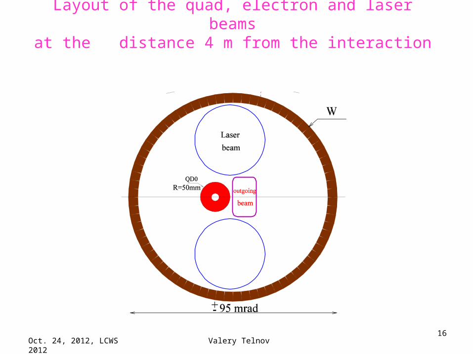
Layout of the quad, electron and laser beamsat the distance 4 m from the interaction point (IP)

Oct. 24, 2012, LCWS 2012 Valery Telnov17
of LLNL laser experts
Oct. 24, 2012, LCWS 2012 Valery Telnov18
Photon collider at CLIC

Oct. 24, 2012, LCWS 2012 Valery Telnov19
The CLIC LayoutDrive Beam Generation Complex
Drive Beam Generation Complex
Main Beam Generation Complex
Main Beam Generation Complex
e+e-
e-e-
γe-
γγ

Oct. 24, 2012, LCWS 2012 Valery Telnov20
CLIC main parameters

Oct. 24, 2012, LCWS 2012 Valery Telnov21
Comparison of ILC and CLIC parameters (important for PLC)
Laser wave length λ E for ILC(250-500) λ~1μm, for CLIC(250-3000) λ~ 1 - 4.5 μmDisruption angle θd~(N/σzEmin)1/2
For CLIC angles θd is larger on 20%, not important difference.Laser flash energy A~10 J for ILC, A~5J for CLICDuration of laser pulse τ~1.5 ps for ILC, τ~1.5 ps for CLIC Pulse structure ILC Δct~100 m, 3000 bunch/train, 5 Hz (fcol~15 kH) CLIC Δct~0.15 m, ~300 bunch/train, 50 Hz (fcol~15 kH)Laser system ILC – a ring optical cavity with Q>100 CLIC –one pass system (or short linear cavity?)
Oct. 24, 2012, LCWS 2012 Valery Telnov22
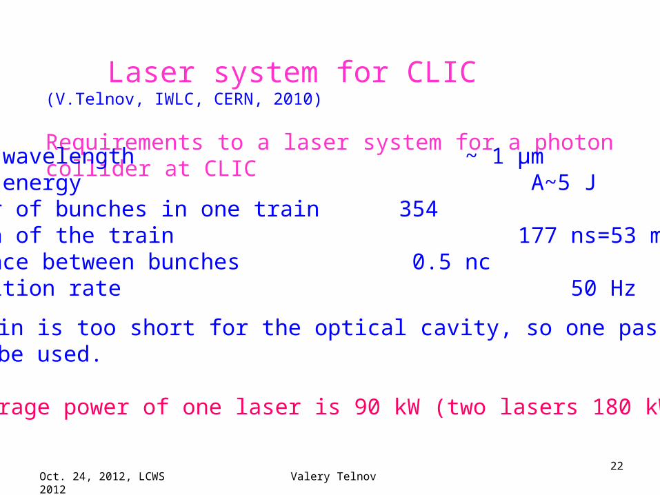
Laser system for CLIC (V.Telnov, IWLC, CERN, 2010)
Requirements to a laser system for a photon collider at CLIC
Laser wavelength ~ 1 μmFlash energy A~5 JNumber of bunches in one train 354Length of the train 177 ns=53 mDistance between bunches 0.5 ncRepetition rate 50 Hz
The train is too short for the optical cavity, so one pass laser should be used.
The average power of one laser is 90 kW (two lasers 180 kW).
Oct. 24, 2012, LCWS 2012 Valery Telnov23
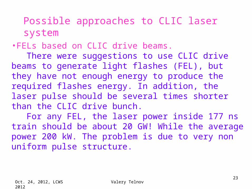
Possible approaches to CLIC laser system
•FELs based on CLIC drive beams. There were suggestions to use CLIC drive beams to generate light flashes (FEL), but they have not enough energy to produce the required flashes energy. In addition, the laser pulse should be several times shorter than the CLIC drive bunch. For any FEL, the laser power inside 177 ns train should be about 20 GW! While the average power 200 kW. The problem is due to very non uniform pulse structure.

Oct. 24, 2012, LCWS 2012 Valery Telnov24
Solid state lasers pumped by diodes. One can use solid state lasers pumped by diodes. There are laser media with a storage time of about 1 ms. One laser train contains the energy about 5x534=2000 J. Efficiency of the diode pumping about 20%, therefore the total power of diodes should be P~2*2000/0.001/0.20~20 MW. At present the cost of only diodes for the laser system will be ~O(100) M$. Experts say that such technology will be available in one decade. LLNL works in this direction for laser fusion applications (λ~1μm).
diodes
amplifire
Most power laser systems with diode pumping have wavelength about 1 μm, exactly what is needed for LC(500).
Oct. 24, 2012, LCWS 2012 Valery Telnov25
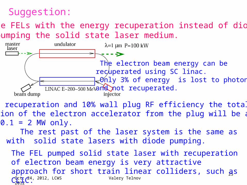
Suggestion:to use FELs with the energy recuperation instead of diodes for pumping the solid state laser medium.
The electron beam energy can be recuperated using SC linac. Only 3% of energy is lost to photons and not recuperated.
With recuperation and 10% wall plug RF efficiency the total power consumption of the electron accelerator from the plug will be about 200 kW/ 0.1 = 2 MW only. The rest past of the laser system is the same as with solid state lasers with diode pumping.
The FEL pumped solid state laser with recuperation of electron beam energy is very attractive approach for short train linear colliders, such as CLIC.
Oct. 24, 2012, LCWS 2012 Valery Telnov26
Storage of the pumping energy inside solid-state laser materials reduces the required FEL power insidethe CLIC train by a factor 1 ms/ 177 ns=5600!
Such FEL can be built already now.

Oct. 24, 2012, LCWS 2012 Valery Telnov27
Another option: linear optical cavity Two mirror cavity is very unstable for small focal sizes, third mirror can reduce requirements to tolerances. The main problem – very large laser power per cm2. Divergence of the laser beam is determined by optimum conditions at the laser focus. Largerdistance – smaller profit from the cavity: Q~25/L(m). This approach needscareful study.
Oct. 24, 2012, LCWS 2012 Valery Telnov28
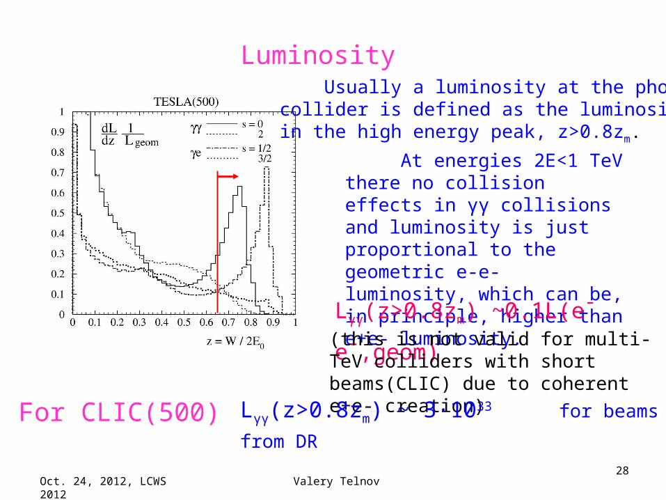
Luminosity
At energies 2E<1 TeV there no collision effects in γγ collisions and luminosity is just proportional to the geometric e-e- luminosity, which can be, in principle, higher than e+e- luminosity.
Lγγ(z>0.8zm) ~0.1L(e-e-,geom) (this is not valid for multi-TeV colliders
with short beams(CLIC) due to coherent e+e- creation)
For CLIC(500) Lγγ(z>0.8zm) ~ 3·1033 for beams from DR
Usually a luminosity at the photon collider is defined as the luminosityin the high energy peak, z>0.8zm.
Oct. 24, 2012, LCWS 2012 Valery Telnov29
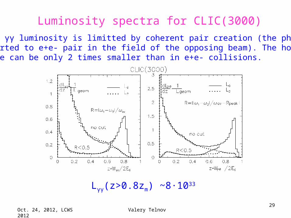
Luminosity spectra for CLIC(3000)
Here the γγ luminosity is limitted by coherent pair creation (the photon is converted to e+e- pair in the field of the opposing beam). The horizontalbeam size can be only 2 times smaller than in e+e- collisions.
Lγγ(z>0.8zm) ~8·1033
Oct. 24, 2012, LCWS 2012 Valery Telnov30
Overlap of hadronic events
The typical number of γγ→had events per bunchcrossing is about 1-2 (both at ILC and CLIC). However, at CLIC the distance between bunches is very short and many events will overlap. A special detector withtime stamps can help but not completely. At ILC the situation is much better. Note, that in e+e- collisions at CLIC(3000) there are also 2.7 γγ→had events per crossing, quite similar to the photon collider.

Oct. 24, 2012, LCWS 2012 Valery Telnov31
Photon collider Higgs factory
SAPPHiRE
Oct. 24, 2012, LCWS 2012 Valery Telnov32
Aug. 2012

Oct. 24, 2012, LCWS 2012 Valery Telnov33

Oct. 24, 2012, LCWS 2012 Valery Telnov34
!!!
50 MW only beams
!!!
!

Oct. 24, 2012, LCWS 2012 Valery Telnov35
The main problem of the recirculating linacis the increase of the horizontal emittance in arcs
SUPPHIRE needs smaller emittance dilution than in existing designs (LHeC), therefore it was suggested to decrease the dipole section length by a factor of 4 and thus to decrease the dilution by a factor of 64!However, it was not noticed that in this case the quads gradient should be 42=16 times larger!

Oct. 24, 2012, LCWS 2012 Valery Telnov36
Main critical remarks on SAPPHIRE1. The emittance dilution in arcs is too optimistic (quad’s gradients
are forgotten, not scaled)2. The initial beam normalized emittances, 5 and 0.5 mm mrad in
X and Y directions corresponds to best emittances of unpolarized RF guns. PLC needs polarized electrons. Present polarized DC guns (polarized RF guns do not exist yet) have emittances > 20 times larger! It means that the luminosity will be 20 times smaller. That is why PLC at ILC assumes DR.
3. Conservation of polarization in rings is a problem (due to the energy spread).
4. The length of the ring 9 km (2.2 km linac, 30 km arcs). The LC with G=30 MeV/m would have L=6 km total length (with the final focus) and can work with smaller emittances and thus can have a higher luminosity. Where is profit?
5. It is obvious that e+e- is better for the Higgs study, there is no chance to get support of physics community, if this collider is instead of e+e-(worse that precursor).

Oct. 24, 2012, LCWS 2012 Valery Telnov37
Dreams of γγ factories

Oct. 24, 2012, LCWS 2012 Valery Telnov38
Factors limiting γγ,γe luminosities
So, one needs: εnx, εny as small as possible and βx , βy ~ σz
Collision effects:•Coherent pair creation (γγ)•Beamstrahlung (γe)•Beam-beam repulsion (γe)
On the right figure:the dependence of γγ and γe luminosities in the high energy peak vs the horizontal beam size (σy is fixed).
At the ILC nominal parameters of electron beams σx ~ 300 nm is available at 2E0=500 GeV. Having beams with smaller emittances one could obtain much higher γγ luminosity. Physics does not forbid an increase of the γγ luminosity by a factor of 30. γe luminosity in the high energy peak is limited by beamstrahlung and beam repulsion.
Telnov,1998
(ILC)

Oct. 24, 2012, LCWS 2012 Valery Telnov39
Having electron beams with smaller emittances one could dream on photon colliders with the γγ-luminosity up to L~1035 in the high energy peak. Collision effects do not restrict the luminosity at 2E<1 TeV. The cross section for the Higgs in γγ is higher than in e+e- by a factor of 5, for any charged pair by a factor of 5-10, so the number of interesting events could be higher by a factor of 20-50 times. The problem – emittances. Damping rings emittances are already near physics limits (due to SR). RF guns give larger product of horizontal and vertical emittances than DRs (determined by the space charge). Moreover, polarized RF guns do not exist yet. What are possible ways to small emittances, to PLC without damping rings?

Oct. 24, 2012, LCWS 2012 Valery Telnov40
Comparizon of transverse emittances in damping rings and photo-guns
The ILC DR (polarized): εnx=10-3 cm, εny=3.6·10-6 cm, βx~4 mm
RF guns (3 nC, unpolarized): εnx=3·10-4 cm, εny=3·10-4 cm, βx~2 mm DC guns (polarized): εnx=7·10-3 cm, εny=7·10-3 cm, βx~4 mm
Lgeom~ F(pol.ench.)/(εnxεnyβxβy)1/2 Fpol.ench ~2-3.5 (depends on the energy)
Very approximately with account of βx variation (chromo-geom.aberrations):
L(DR)/ L(RFguns,unpol)~ 7-12L(DR)/ L(DCguns,pol) ~ 100
Therefore until now DRs were considered as a preferable source of electrons for the PLC.

Oct. 24, 2012, LCWS 2012 Valery Telnov41
What to do?
Method №1
The most promising way is the laser cooling of electronbeams for linear colliders (V.Telnov, 1987). This method allows to reach the desired small transverse emittances and preserves the longitudinal polarization. As injector the DC polarized gun can be used. Progress in laser optical cavities makes the goal more and more realistic. The method needs a more detailed consideration and optimization.
Oct. 24, 2012, LCWS 2012 Valery Telnov42
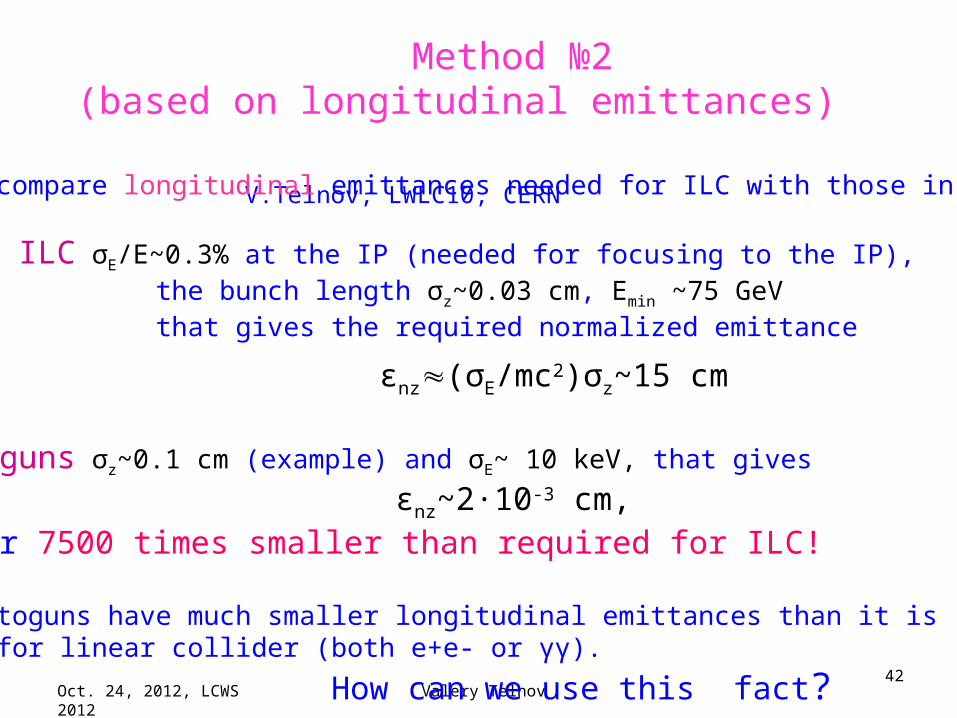
Method №2(based on longitudinal emittances)
V.Telnov, LWLC10, CERN
Let us compare longitudinal emittances needed for ILC with those in RF guns.
At the ILC σE/E~0.3% at the IP (needed for focusing to the IP), the bunch length σz~0.03 cm, Emin ~75 GeV that gives the required normalized emittance
εnz(σE/mc2)σz~15 cm
In RF guns σz~0.1 cm (example) and σE~ 10 keV, that gives
εnz~2·10-3 cm, or 7500 times smaller than required for ILC!
So, photoguns have much smaller longitudinal emittances than it is needed for linear collider (both e+e- or γγ).
How can we use this fact?
Oct. 24, 2012, LCWS 2012 Valery Telnov43
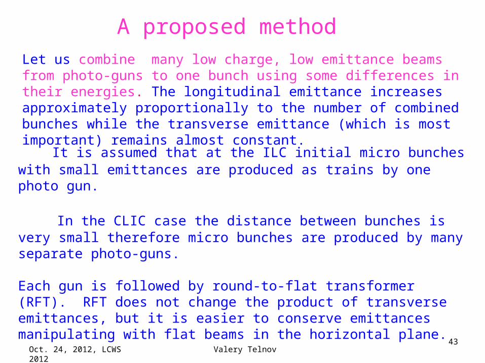
Let us combine many low charge, low emittance beams from photo-guns to one bunch using some differences in their energies. The longitudinal emittance increases approximately proportionally to the number of combined bunches while the transverse emittance (which is most important) remains almost constant.
A proposed method
It is assumed that at the ILC initial micro bunches with small emittances are produced as trains by one photo gun.
In the CLIC case the distance between bunches is very small therefore micro bunches are produced by many separate photo-guns.
Each gun is followed by round-to-flat transformer (RFT). RFT does not change the product of transverse emittances, but it is easier to conserve emittances manipulating with flat beams in the horizontal plane.
Below the scheme for the ILC case is considered.
Oct. 24, 2012, LCWS 2012 Valery Telnov44
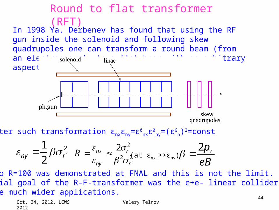
In 1998 Ya. Derbenev has found that using the RF gun inside the solenoid and following skew quadrupoles one can transform a round beam (from an electron gun) to a flat beam with an arbitrary aspect ratio.
Round to flat transformer (RFT)
After such transformation εnxεny=ε0nxε0
ny=(εGn)2=const
2
2
1rny
22
22
r
r
ny
nxR
eB
pz2(at εnx.>>εny)
The ratio R=100 was demonstrated at FNAL and this is not the limit.The initial goal of the R-F-transformer was the e+e- linear collider, but now there are much wider applications.
Oct. 24, 2012, LCWS 2012 Valery Telnov45
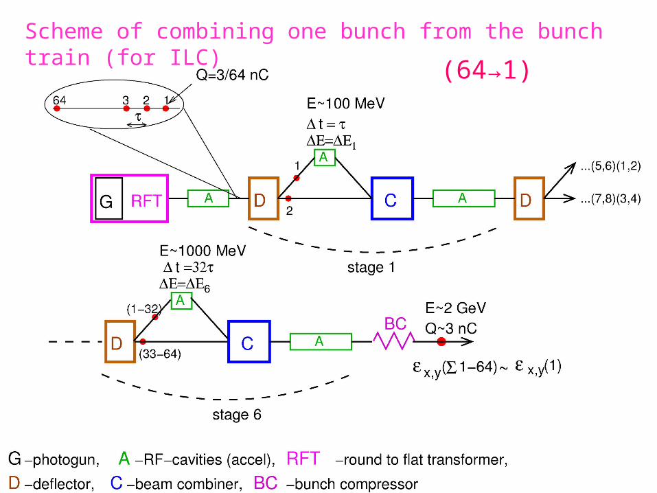
Scheme of combining one bunch from the bunch train (for ILC)
(64→1)

Oct. 24, 2012, LCWS 2012 Valery Telnov46
Oct. 24, 2012, LCWS 2012 Valery Telnov47
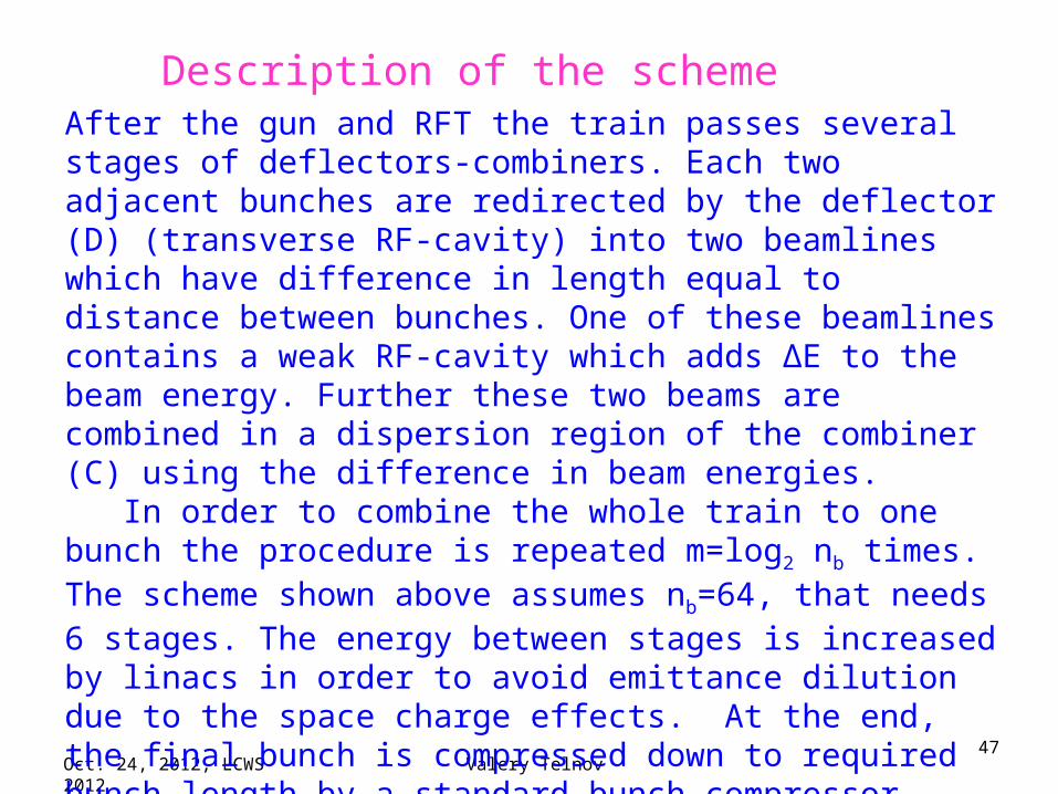
After the gun and RFT the train passes several stages of deflectors-combiners. Each two adjacent bunches are redirected by the deflector (D) (transverse RF-cavity) into two beamlines which have difference in length equal to distance between bunches. One of these beamlines contains a weak RF-cavity which adds ΔE to the beam energy. Further these two beams are combined in a dispersion region of the combiner (C) using the difference in beam energies. In order to combine the whole train to one bunch the procedure is repeated m=log2 nb times. The scheme shown above assumes nb=64, that needs 6 stages. The energy between stages is increased by linacs in order to avoid emittance dilution due to the space charge effects. At the end, the final bunch is compressed down to required bunch length by a standard bunch compressor. For more details see the talk at LWLC10.
Description of the scheme
Oct. 24, 2012, LCWS 2012 Valery Telnov48
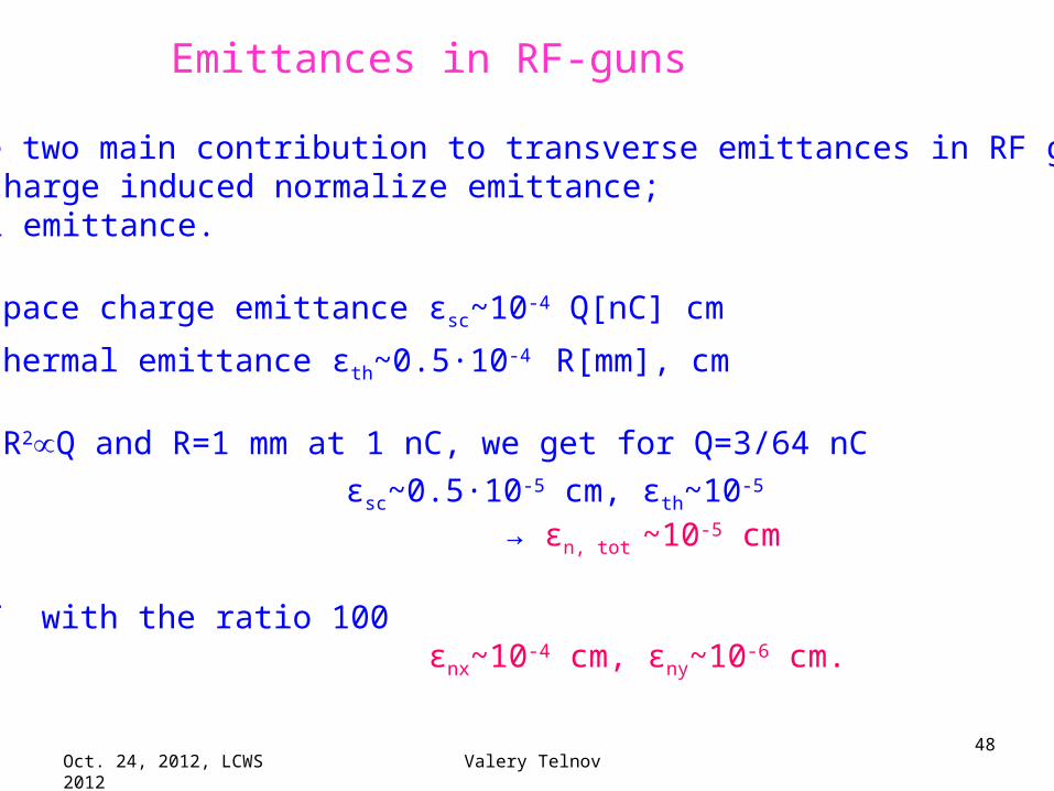
Emittances in RF-guns
There are two main contribution to transverse emittances in RF guns:1. Space charge induced normalize emittance;2. Thermal emittance.
The space charge emittance εsc~10-4 Q[nC] cm
The thermal emittance εth~0.5·10-4 R[mm], cm Assuming R2Q and R=1 mm at 1 nC, we get for Q=3/64 nC
εsc~0.5·10-5 cm, εth~10-5
→ εn, tot ~10-5 cm
After RFT with the ratio 100 εnx~10-4 cm, εny~10-6 cm.
Oct. 24, 2012, LCWS 2012 Valery Telnov49
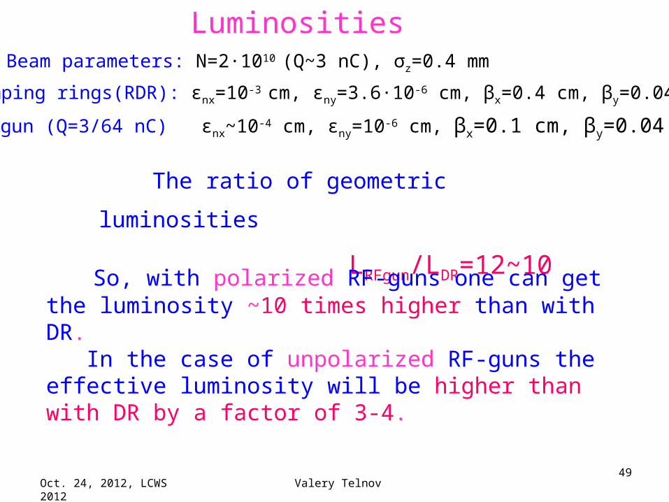
Beam parameters: N=2·1010 (Q~3 nC), σz=0.4 mm
Damping rings(RDR): εnx=10-3 cm, εny=3.6·10-6 cm, βx=0.4 cm, βy=0.04 cm,
RF-gun (Q=3/64 nC) εnx~10-4 cm, εny=10-6 cm, βx=0.1 cm, βy=0.04 cm,
The ratio of geometric luminosities
LRFgun/LDR=12~10
Luminosities
So, with polarized RF-guns one can get the luminosity ~10 times higher than with DR. In the case of unpolarized RF-guns the effective luminosity will be higher than with DR by a factor of 3-4.
Oct. 24, 2012, LCWS 2012 Valery Telnov50
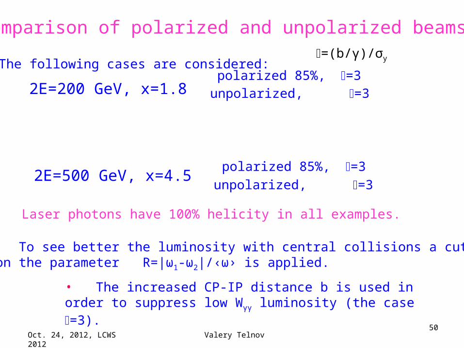
Comparison of polarized and unpolarized beams
The following cases are considered:
2E=200 GeV, x=1.8 polarized 85%, =3unpolarized, =3
2E=500 GeV, x=4.5 polarized 85%, =3
unpolarized, =3
=(b/γ)/σy
• To see better the luminosity with central collisions a cut on the parameter R=|ω1-ω2|/‹ω› is applied.
• The increased CP-IP distance b is used in order to suppress low Wγγ luminosity (the case =3).
Laser photons have 100% helicity in all examples.
Oct. 24, 2012, LCWS 2012 Valery Telnov51
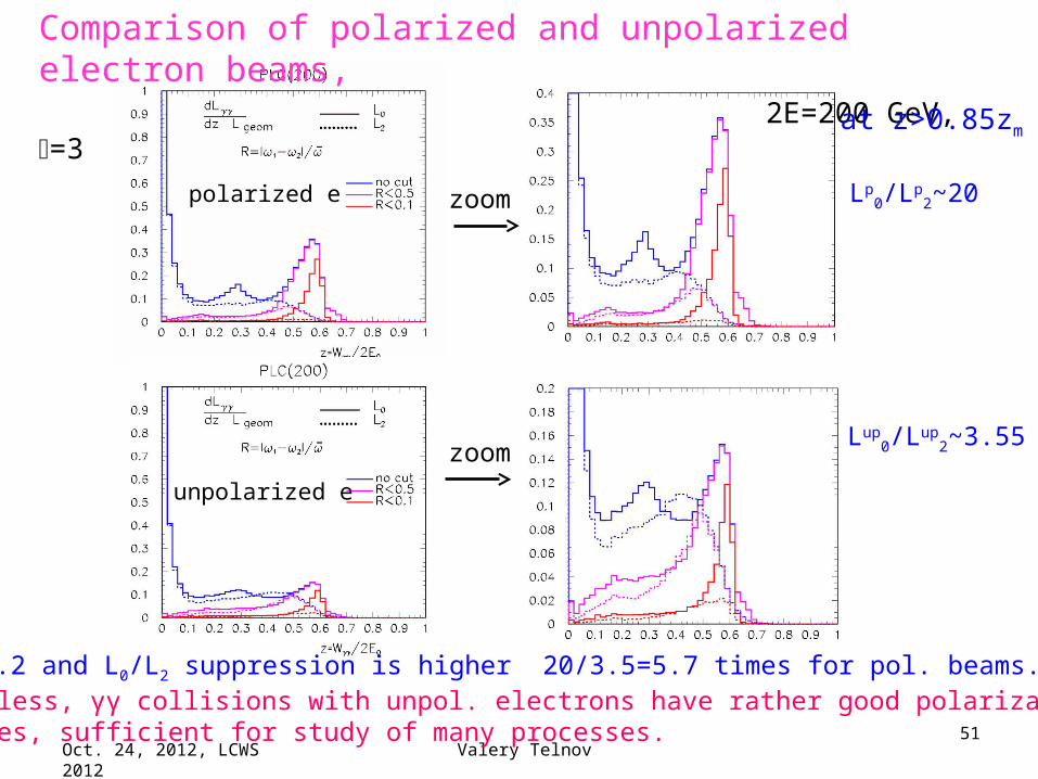
Comparison of polarized and unpolarized electron beams, 2E=200 GeV, =3
zoom
zoompolarized e
unpolarized e
at z>0.85zm
Lp0/Lp
2~20
Lup0/Lup
2~3.55
Lp0/Lup
0=2.2 and L0/L2 suppression is higher 20/3.5=5.7 times for pol. beams.Nevertheless, γγ collisions with unpol. electrons have rather good polarization properties, sufficient for study of many processes.
Oct. 24, 2012, LCWS 2012 Valery Telnov52
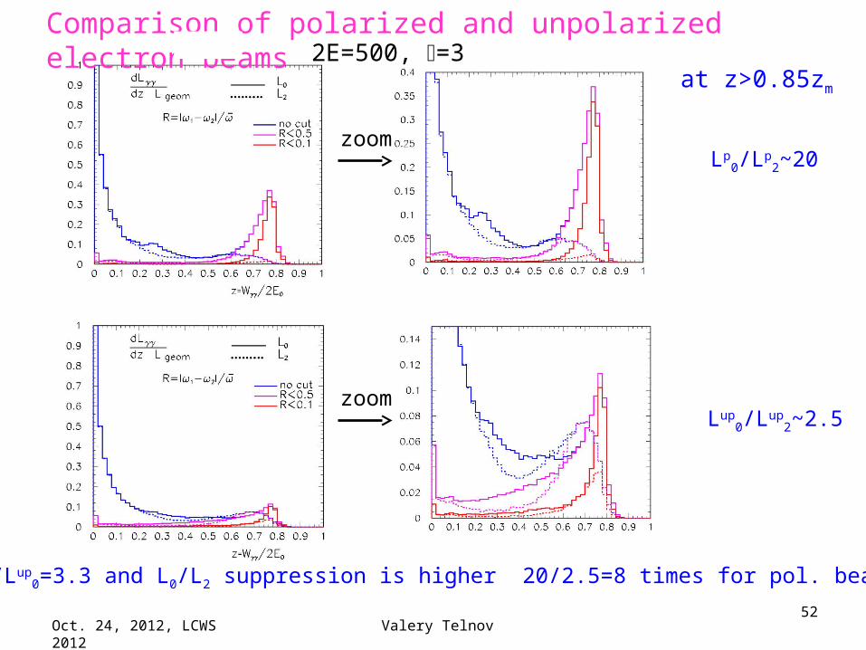
Comparison of polarized and unpolarized electron beams 2E=500, =3
zoom
zoom
at z>0.85zm
Lp0/Lp
2~20
Lup0/Lup
2~2.5
Lp0/Lup
0=3.3 and L0/L2 suppression is higher 20/2.5=8 times for pol. beams.

Oct. 24, 2012, LCWS 2012 Valery Telnov53
Summary on low emittances with guns
Polarized RF-gunsHaving polarized RF guns with emittances similar to existing unpolarizedguns we could obtain the γγ luminosity ~10 times higher than that
with ILCDRs (all polarization characteristics are similar). Unpolarized RF-gunsAlready with existing RF guns we can dream on the γγ luminosity higherthan with DR by a factor of 10/Fpol.ench.., where Fp.e.~2.2-3.3 for
2E=200-
500 GeV. The γγ luminosity will be about ~3-4 times higher than with DR,but L0/L2 in the high energy peak will be only 3.5-2.5 instead of 20 forpolarized beams, which is acceptable (the case of H(120) should bechecked).
Possible technical problems in suggested technique1. Dilution of the emittance due to wakefields in combiner sections.2. All parameters of beamlines should be continuously adjusted in order to
combine all 64 bunches to the same phase space (except energy).
The above ideas should be proved by realistic consideration-optimization.
Oct. 24, 2012, LCWS 2012 Valery Telnov54
Conclusion• Photon colliders have sense as a very cost effective addition for
e+e- colliders: as the LC second stage or as the second IP (preferable).
• PLC at ILC is conceptually clear, the next step is the design and construction of the laser system prototype.
• PLC at CLIC is more difficult due to much shorter trains. The solution is visible, need a detailed study.
• PLC SAPPHIRE proposal is based on two mistakes, one of them can be corrected by increasing PLC radius, the second can be corrected only by adding damping rings. In any case, the PLC for Higgs without e+e- has not sufficient physics case.
• PLC without damping rings is possible, could have even higher (or much higher) luminosity, needs further study. That could open the way to γγ factories, to precision measurement of the Higgs self coupling etc (if there is any new physics in the sub-TeV region).