User’s Manual for the NETGEAR Super AG Wireless USB 2.0 Adapter
108
202-10065-01 202-10065-01 November 2004 NETGEAR, Inc. 4500 Great America Parkway Santa Clara, CA 95054 USA User’s Manual for the NETGEAR Super AG Wireless USB 2.0 Adapter WG111U ΤΜ
Transcript of User’s Manual for the NETGEAR Super AG Wireless USB 2.0 Adapter

202-100
User’s Manual for the NETGEAR Super AG Wireless USB 2.0 Adapter WG111U
ΤΜ
65-01
202-10065-01 November 2004
NETGEAR, Inc.4500 Great America Parkway Santa Clara, CA 95054 USA
Technical Support
Please refer to the support information card that shipped with your product. By registering your product at http://ww.netgear.com/register, we can provide you with faster expert technical support and timely notices of product and software upgrades.
NETGEAR, INC. Support Information
Phone: 1-888-NETGEAR, for US & Canada only. For other countries, see your Support information card.
E-mail: [email protected]
Web site: http://www.netgear.com
Statement of Conditions
In the interest of improving internal design, operational function, and/or reliability, NETGEAR reserves the right to make changes to the products described in this document without notice.NETGEAR does not assume any liability that may occur due to the use or application of the product(s) or circuit layout(s) described herein.
©2004 NETGEAR, Inc. NETGEAR, the NETGEAR logo, The Gear Guy and Everybody's Connecting are trademarks or registered trademarks of NETGEAR, Inc. in the United States and/or other countries. Microsoft and Windows are registered trademarks of Microsoft Corporation in the United States and/or other countries. Other brand and product names are trademarks or registered trademarks of their respective holders. Information is subject to change without notice. All rights reserved.
November 2004
Certificate of the Manufacturer/Importer
It is hereby certified that the Model WG111U Wireless USB 2.0 Adapter has been suppressed in accordance with the conditions set out in the BMPT- AmtsblVfg 243/1991 and Vfg 46/1992. The operation of some equipment (for example, test transmitters) in accordance with the regulations may, however, be subject to certain restrictions. Please refer to the notes in the operating instructions. Federal Office for Telecommunications Approvals has been notified of the placing of this equipment on the market and has been granted the right to test the series for compliance with the regulations.
FCC Information to User
This product does not contain any user serviceable components and is to be used with approved antennas only. Any product changes or modifications will invalidate all applicable regulatory certifications and approvals.
ii
202-10065-01

FCC Guidelines for Human Exposure
This equipment complies with FCC radiation exposure limits set forth for an uncontrolled environment. This equipment should be installed and operated with minimum distance of 20 cm between the radiator and your body. This transmitter must not be co-located or operating in conjunction with any other antenna or transmitter.
Declaration Of Conformity
We NETGEAR, Inc., 4500 Great America Parkway, Santa Clara, CA 95054, declare under our sole responsibility that the model WG111U Wireless USB 2.0 Adapter complies with Part 15 of FCC Rules. Operation is subject to the following two conditions:• This device may not cause harmful interference, and• This device must accept any interference received, including interference that may cause undesired operation.
Regulatory Compliance Information
This section includes user requirements for operating this product in accordance with National laws for usage of radio spectrum and operation of radio devices. Failure of the end-user to comply with the applicable requirements may result in unlawful operation and adverse action against the end-user by the applicable National regulatory authority.
NOTE: This product's firmware limits operation to only the channels allowed in a particular Region or Country. Therefore, all options described in this user's guide may not be available in your version of the product.
FCC Requirements for Operation in the United States
Radio Frequency Interference Warnings & InstructionsThis equipment has been tested and found to comply with the limits for a Class B digital device, pursuant to Part 15 of the FCC Rules. These limits are designed to provide reasonable protection against harmful interference in a residential installation. This equipment uses and can radiate radio frequency energy and, if not installed and used in accordance with the instructions, may cause harmful interference to radio communications. However, there is no guarantee that interference will not occur in a particular installation. If this equipment does cause harmful interference to radio or television reception, which can be determined by turning the equipment off and on, the user is encouraged to try to correct the interference by one or more of the following methods:• Reorient or relocate the receiving antenna• Increase the separation between the equipment and the receiver• Connect the equipment into an electrical outlet on a circuit different from that which the radio receiver is connected• Consult the dealer or an experienced radio/TV technician for help.
Modifications made to the product, unless expressly approved by NETGEAR, Inc., could void the user's right to operate the equipment.
FOR HOME OR OFFICE USE
Tested to Complywith FCC Standards
NETGEAR Super AG Wireless USB 2.0 Adapter WG111U
PY3WG111U
202-10065-01
iii
Export Restrictions
This product or software contains encryption code which may not be exported or transferred from the US or Canada without an approved US Department of Commerce export license.
Europe - EU Declaration of Conformity
This product is certified for Switzerland and all EU countries. Marking by the above symbol indicates compliance with the Essential Requirements of the R&TTE Directive of the European Union (1999/5/EC). This equipment meets the following conformance standards: EN300 328, EN301 489-17, EN60950
Requirements For Operation in the European Community
Countries of Operation and Conditions of Use in the European Community
The user should run the client utility program provided with this product to check the current channel of operation and confirm that the device is operating in conformance with the spectrum usage rules for European Community countries as described in this section.This device is intended to be operated in all countries of the European Community.
Operation Using 2.4 GHz Channels in France
The following radio channel usage limitations apply in France. The radio spectrum regulator in France, Autorité de regulation des telecommunications (ART), enforces the following rules with respect to use of 2.4GHz spectrum in various locations in France. Please check ART's web site for latest requirements for use of the 2.4GHz band in France: http://www.art-telecom.fr/eng/index.htm. When operating in the following metropolitan regions (départements) in France, this device may be operated under the following conditions:Indoors using any channel in the 2.4-2.4835 GHz band (Channels 1-13)Outdoors using channels in the 2.4-2.454 GHz band (Channels 1-7)When operating outside of the following regions (départements) in France (see table below), this product must be operated under the following conditions:• Indoors using channels in the 2.4465-2.4835 GHz band (Channels 10-13).• Outdoor operation not permitted.Please refer to the ART web site for further details.
This device is a 2.4/5.0 GHz dual-band low power RF device intended for home and office use in EU and EFTA member states. In some EU / EFTA member states some restrictions may apply. Please contact local spectrum management authorities for further details before putting this device into operation.
202-10065-01
iv

Metropolitan Regions with Eased Restrictions in 2.4GHz Band
Countries of Operation & Conditions of Use in the European Community
Note: The user should use the configuration utility provided with this product to check the current channel of operation and confirm that the device is operating in conformance with the spectrum usage rules for European Community countries. If operation is occurring outside of the allowable channels as indicated in this guide, then the user must cease operating the product.This device is intended to be operated in all countries of the European Community. Requirements for indoor vs. outdoor operation, license requirements and allowed channels of operation apply as described in this document.• This device is restricted to indoor use when operated in the European Community using the 5.15-5.35GHz band:
Channels 36, 40, 44, 48, 52, 56, 60, 64. See table below for allowed 5GHz channels by country.• This device may be operated indoors or outdoors in all countries of the European Community using the 2.4GHz
band: Channels 1 - 13, except where noted below. • In Italy the end-user must apply for a license from the national spectrum authority to operate this device outdoors. • Belgium requires notifying spectrum agency if deploying >300 meter wireless links in outdoor public areas using
2.4GHz band.• In France outdoor operation is only permitted using the 2.4 - 2.454 GHz band: Channels 1 - 7.• The 5GHz Turbo mode feature is not allowed for operation in any European Community country.• This device must not be operated in ad-hoc mode using channels in the 5GHz bands in the European Community.
Ad-hoc mode is direct communication between two client devices without an Access Point.
202-10065-01
v
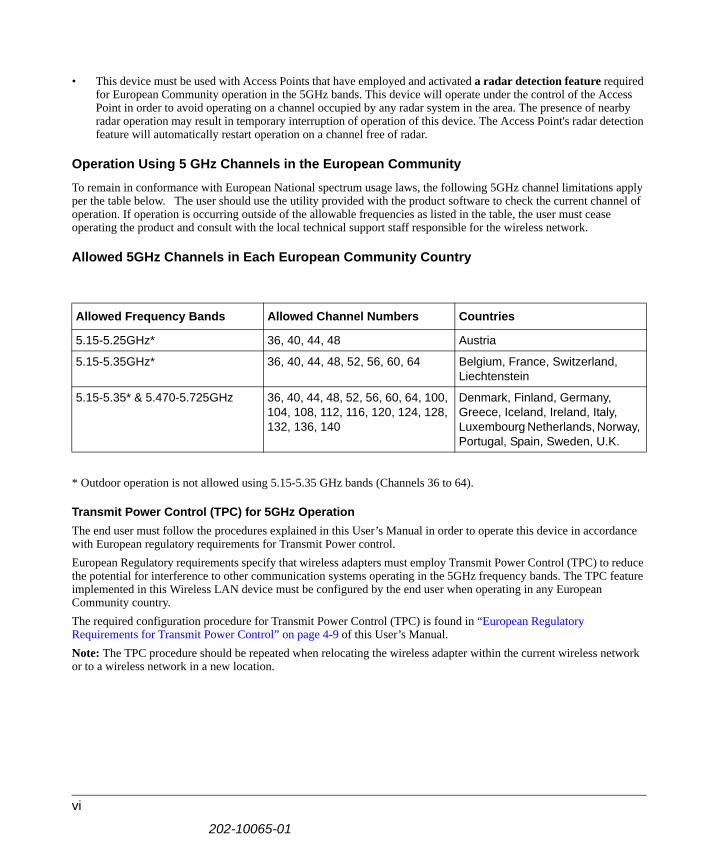
• This device must be used with Access Points that have employed and activated a radar detection feature required for European Community operation in the 5GHz bands. This device will operate under the control of the Access Point in order to avoid operating on a channel occupied by any radar system in the area. The presence of nearby radar operation may result in temporary interruption of operation of this device. The Access Point's radar detection feature will automatically restart operation on a channel free of radar.
Operation Using 5 GHz Channels in the European Community
To remain in conformance with European National spectrum usage laws, the following 5GHz channel limitations apply per the table below. The user should use the utility provided with the product software to check the current channel of operation. If operation is occurring outside of the allowable frequencies as listed in the table, the user must cease operating the product and consult with the local technical support staff responsible for the wireless network.
Allowed 5GHz Channels in Each European Community Country
* Outdoor operation is not allowed using 5.15-5.35 GHz bands (Channels 36 to 64).
Transmit Power Control (TPC) for 5GHz OperationThe end user must follow the procedures explained in this User’s Manual in order to operate this device in accordance with European regulatory requirements for Transmit Power control.European Regulatory requirements specify that wireless adapters must employ Transmit Power Control (TPC) to reduce the potential for interference to other communication systems operating in the 5GHz frequency bands. The TPC feature implemented in this Wireless LAN device must be configured by the end user when operating in any European Community country. The required configuration procedure for Transmit Power Control (TPC) is found in “European Regulatory Requirements for Transmit Power Control” on page 4-9 of this User’s Manual.Note: The TPC procedure should be repeated when relocating the wireless adapter within the current wireless network or to a wireless network in a new location.
Allowed Frequency Bands Allowed Channel Numbers Countries
5.15-5.25GHz* 36, 40, 44, 48 Austria
5.15-5.35GHz* 36, 40, 44, 48, 52, 56, 60, 64 Belgium, France, Switzerland, Liechtenstein
5.15-5.35* & 5.470-5.725GHz 36, 40, 44, 48, 52, 56, 60, 64, 100, 104, 108, 112, 116, 120, 124, 128, 132, 136, 140
Denmark, Finland, Germany, Greece, Iceland, Ireland, Italy, Luxembourg Netherlands, Norway, Portugal, Spain, Sweden, U.K.
202-10065-01
vi

Declaration of Conformity in Languages of the European Community English Hereby, NETGEAR Inc. declares that this Radio LAN device is in compliance with the essential
requirements and other relevant provisions of Directive 1999/5/EC.
Finnish Valmistaja NETGEAR Inc. vakuuttaa täten että Radio LAN device tyyppinen laite on direktiivin 1999/5/EY oleellisten vaatimusten ja sitä koskevien direktiivin muiden ehtojen mukainen.
Dutch Hierbij verklaart NETGEAR Inc. dat het toestel Radio LAN device in overeenstemming is met de essentiële eisen en de andere relevante bepalingen van richtlijn 1999/5/EG
Bij deze NETGEAR Inc. dat deze Radio LAN device voldoet aan de essentiële eisen en aan de overige relevante bepalingen van Richtlijn 1999/5/EC.
French Par la présente NETGEAR Inc. déclare que l'appareil Radio LAN device est conforme aux exigences essentielles et aux autres dispositions pertinentes de la directive 1999/5/CE
Swedish Härmed intygar NETGEAR Inc. att denna Radio LAN device står I överensstämmelse med de väsentliga egenskapskrav och övriga relevanta bestämmelser som framgår av direktiv 1999/5/EG.
Danish Undertegnede NETGEAR Inc. erklærer herved, at følgende udstyr Radio LAN device overholder de væsentlige krav og øvrige relevante krav i direktiv 1999/5/EF
Hiermit erklärt NETGEAR Inc. dass sich dieser/diese/dieses Radio LAN device in Übereinstimmung mit den grundlegenden Anforderungen und den anderen relevanten Vorschriften der Richtlinie 1999/5/EG befindet". (BMWi)
German
Hiermit erklärt NETGEAR Inc. die Übereinstimmung des Gerätes Radio LAN device mit den grundlegenden Anforderungen und den anderen relevanten Festlegungen der Richtlinie 1999/5/EG. (Wien)
Greek NETGEAR Inc. Radio LAN device 1999/5/
Italian Con la presente NETGEAR Inc. dichiara che questo Radio LAN device è conforme ai requisiti essenziali ed alle altre disposizioni pertinenti stabilite dalla direttiva 1999/5/CE.
Spanish Por medio de la presente NETGEAR Inc. declara que el Radio LAN device cumple con los requisitos esenciales y cualesquiera otras disposiciones aplicables o exigibles de la Directiva 1999/5/CE
Portuguese NETGEAR Inc. declara que este Radio LAN device está conforme com os requisitos essenciais e oudisposições da Directiva 1999/5/CE.
202-10065-01
vii

Canadian Department of Communications Radio Interference Regulations
This digital apparatus (WG111U Wireless USB 2.0 Adapter) does not exceed the Class B limits for radio-noise emissions from digital apparatus as set out in the Radio Interference Regulations of the Canadian Department of Communications.Canada ID: 4054A-WG111U
202-10065-01
viii

Contents
Chapter 1 About This Manual
Audience, Scope, Conventions ......................................................................................1-1How to Use this Manual ..................................................................................................1-2How to Print this Manual .................................................................................................1-3
Chapter 2 Introduction
About the WG111U .........................................................................................................2-1Key Features ..................................................................................................................2-2
802.11a and 802.11b/g Wireless Networking ...........................................................2-2Comparing the 802.11a, 802.11b, and 802.11g Modes ..................................................2-3What’s in the Box? ..........................................................................................................2-4A Road Map for ‘How to Get There From Here’ .............................................................2-4
Chapter 3 Basic Setup
What You Need Before You Begin ..................................................................................3-1Verifying System Requirements ...............................................................................3-1Observing Location and Range Guidelines ..............................................................3-2Determining Placement of the USB Adapter ............................................................3-2
Two Basic Operating Modes ...........................................................................................3-3WG111U Default Wireless Configuration Settings ..........................................................3-4Basic Installation Instructions .........................................................................................3-4
For Windows XP Users Installing a WG111U ...........................................................3-5For Windows 2000, ME, and 98SE Users Installing a WG111U ..............................3-9
WG111U Wireless Connection Indicators .....................................................................3-12Interpreting the LED on the WG111U .....................................................................3-13Interpreting System Tray Icon Colors .....................................................................3-14
Contents ix
202-10065-01

Chapter 4 Configuration
Understanding the Configuration Options ......................................................................4-1Using Configuration Profiles ...........................................................................................4-1
Connecting to an Access Point in Infrastructure Mode ............................................4-2How to Configure an Infrastructure Mode Profile .....................................................4-2
Connecting to Another PC in Ad-hoc Mode ....................................................................4-4How to Configure an Ad-hoc Mode Profile ...............................................................4-4
What’s on the Statistics Page? .......................................................................................4-7Understanding the Advanced Settings Page ..................................................................4-8
European Regulatory Requirements for Transmit Power Control ............................4-9Chapter 5 Wireless Security Configuration
Understanding the Security Options ...............................................................................5-1Using WEP Security .......................................................................................................5-2
Basic Requirements for WEP ...................................................................................5-2WEP Security Settings Worksheet ...........................................................................5-3How to Configure WEP Encryption Security ............................................................5-4
Using WPA-PSK Advanced Security ..............................................................................5-5Basic Requirements for WPA-PSK ..........................................................................5-5WPA-PSK Security Settings Worksheet ...................................................................5-6How to Configure WPA-PSK Advanced Security .....................................................5-6
Chapter 6 Troubleshooting
Basic Tips .......................................................................................................................6-1Frequently Asked Questions ..........................................................................................6-2
General Questions ...................................................................................................6-2Why do I see no more than 54 Mbps on the Configuration Utility status line? ..6-2The WG111U Smart Configuration Utility keeps asking me to save my settings 6-2Ad Hoc mode is not working correctly ...............................................................6-2How to know if the WG111U card has received a valid IP address ...................6-3How to use XP’s own Wireless configuration utility ...........................................6-3I cannot connect to the AP that I want from the Networks browser list .............6-3New Hardware Wizard appears after installation has completed ......................6-3How to get a PDF copy of the Manual ...............................................................6-3
202-10065-01
x Contents

Appendix A Technical SpecificationsAppendix B Wireless Networking Basics
Wireless Networking Overview ...................................................................................... B-1Infrastructure Mode ................................................................................................. B-1Ad Hoc Mode (Peer-to-Peer Workgroup) ................................................................ B-2Network Name: Extended Service Set Identification (ESSID) ................................ B-2Wireless Channels .................................................................................................. B-2
WEP Wireless Security .................................................................................................. B-4WEP Authentication ................................................................................................ B-4WEP Open System Authentication ......................................................................... B-5WEP Shared Key Authentication ............................................................................ B-6
Key Size and Configuration .............................................................................. B-7How to Use WEP Parameters ................................................................................. B-8
WPA Wireless Security .................................................................................................. B-8How Does WPA Compare to WEP? ........................................................................ B-9How Does WPA Compare to IEEE 802.11i? ........................................................ B-10What are the Key Features of WPA Security? ...................................................... B-10
WPA Authentication: Enterprise-level User Authentication via 802.1x/EAP and RADIUS .................................................. B-12WPA Data Encryption Key Management ........................................................ B-14
Is WPA Perfect? .................................................................................................... B-16Product Support for WPA ...................................................................................... B-16
Supporting a Mixture of WPA and WEP Wireless Clients ............................... B-16Changes to Wireless Access Points ............................................................... B-16Changes to Wireless Network Adapters ......................................................... B-17Changes to Wireless Client Programs ............................................................ B-18
Appendix C Preparing Your Network to Work with a Router
What You Need To Use a Router with a Broadband Modem ......................................... C-1Cabling and Computer Hardware ............................................................................ C-1Computer Network Configuration Requirements .................................................... C-1Internet Configuration Requirements ...................................................................... C-2Where Do I Get the Internet Configuration Parameters? ........................................ C-2Record Your Internet Connection Information ......................................................... C-3
Contents xi
202-10065-01
Preparing Your Computers for TCP/IP Networking ....................................................... C-4Configuring Windows 95, 98, and Me for TCP/IP Networking ....................................... C-5
Installing or Verifying Windows Networking Components ....................................... C-5Installing a New Adapter ................................................................................... C-5Installing TCP/IP ............................................................................................... C-6Installing the Client for Microsoft Networks ....................................................... C-6
Enabling DHCP to Automatically Configure TCP/IP Settings in Windows 95B, 98, and Me .............................................................................................................. C-6Selecting the Windows’ Internet Access Method .................................................... C-8Verifying TCP/IP Properties .................................................................................... C-8
Configuring Windows NT4, 2000 or XP for IP Networking ............................................ C-9Installing or Verifying Windows Networking Components ....................................... C-9Configuring DHCP of TCP/IP in Windows XP, 2000, or NT4 ................................ C-10DHCP Configuration of TCP/IP in Windows XP ................................................... C-10DHCP Configuration of TCP/IP in Windows 2000 ................................................ C-12DHCP Configuration of TCP/IP in Windows NT4 .................................................. C-14Verifying TCP/IP Properties for Windows XP, 2000, and NT4 .............................. C-15
Configuring the Macintosh for TCP/IP Networking ...................................................... C-16MacOS 8.6 or 9.x .................................................................................................. C-16MacOS X ............................................................................................................... C-16Verifying TCP/IP Properties for Macintosh Computers ......................................... C-17
Verifying the Readiness of Your Internet Account ....................................................... C-17Are Login Protocols Used? ................................................................................... C-18What Is Your Configuration Information? .............................................................. C-18Obtaining ISP Configuration Information for Windows Computers ....................... C-19Obtaining ISP Configuration Information for Macintosh Computers ..................... C-20
Restarting the Network ................................................................................................ C-20 Glossary Index
202-10065-01
xii Contents

User’s Manual for the NETGEAR Super AG Wireless USB 2.0 Adapter WG111U
Chapter 1About This Manual
This chapter introduces the conventions and features of this document.
Audience, Scope, Conventions
This manual assumes that the reader has basic to intermediate computer and Internet skills. However, tutorial information is provided in the Appendices, on the NETGEAR Super AG Wireless USB 2.0 Adapter WG111U Resource CD, and on the NETGEAR Web site.This manual uses the following typographical conventions:
This manual uses the following formats to highlight special messages:
This manual is written according to these specifications:
Table 1. Typographical conventions
italics Emphasis.
bold times roman User input.
SMALL CAPS DOS file and directory names.
Note: This format is used to highlight information of importance or special interest.
Table 1-1. Manual Specifications
Product Version NETGEAR Super AG Wireless USB 2.0 Adapter WG111U
Manual Part Number 202-10065-01
Manual Publication Date November 2004
Note: Product updates are available on the NETGEAR Web site at www.netgear.com/support/main.asp.
About This Manual 1-1
202-10065-01

User’s Manual for the NETGEAR Super AG Wireless USB 2.0 Adapter WG111U
How to Use this ManualThe HTML version of this manual includes these features.
Figure 1-1: HTML version of this manual
1. Left pane. Use the left pane to view the Contents, Index, and Search tabs. To view the HTML version of the manual, you must have a version 4 or later browser with JavaScript enabled.
2. Toolbar buttons. Use the toolbar buttons across the top to navigate, print pages, and more.
The Show in Contents button locates the current topic in the Contents tab.
Previous/Next buttons display the previous or next topic.
The PDF button links to a PDF version of the full manual.
The Print button prints the current topic. Using this button when a step-by-step procedure is displayed will send the entire procedure to your printer--you do not have to worry about specifying the correct range of pages.
3. Right pane. Use the right pane to view the contents of the manual. Also, each page of the manual includes a link at the top right which links to a PDF file containing just the currently selected chapter of the manual.
1 23
1-2 About This Manual
202-10065-01

User’s Manual for the NETGEAR Super AG Wireless USB 2.0 Adapter WG111U
How to Print this ManualTo print this manual you can choose one of the following several options, according to your needs.• Printing a “How To” Sequence of Steps in the HTML View. Use the Print button on the
upper right of the toolbar to print the currently displayed topic. Using this button when a step-by-step procedure is displayed will send the entire procedure to your printer--you do not have to worry about specifying the correct range of pages.
• Printing a Chapter. Use the link at the top right of any page.
– Click “PDF of This Chapter” link at the top right of any page in the chapter you want to print. A new browser window opens showing the PDF version of the chapter you were viewing.
– Click the print icon in the upper left of the window. – Tip: If your printer supports printing two pages on a single sheet of paper, you can save
paper and printer ink by selecting this feature.
• Printing the Full Manual. Use the PDF button in the toolbar at the top right of the browser window.
– Click PDF button. A new browser window opens showing the PDF version of the chapter you were viewing.
– Click the print icon in the upper left of the window. – Tip: If your printer supports printing two pages on a single sheet of paper, you can save
paper and printer ink by selecting this feature.
About This Manual 1-3
202-10065-01

User’s Manual for the NETGEAR Super AG Wireless USB 2.0 Adapter WG111U
1-4 About This Manual
202-10065-01

User’s Manual for the NETGEAR Super AG Wireless USB 2.0 Adapter WG111U
Chapter 2Introduction
This chapter introduces the features, package contents, and appearance of the NETGEAR Super AG Wireless USB 2.0 Adapter WG111U.
About the WG111U
The NETGEAR Super AG Wireless USB 2.0 Adapter WG111U gives you ultimate mobility in your office or while you are traveling. It frees you from traditional Ethernet wiring and helps you create a wireless network for sharing your broadband Internet access among multiple PCs in and around your home. The WG111U is designed for PC computers running Microsoft® Windows®. It is a USB 2.0 device and is backwards compatible with USB 1.1 ports.
Its auto-sensing capability allows high packet transfer at up to 108 Mbps for maximum throughput or dynamic range shifting to lower speeds due to distance or operating limitations in an environment with a lot of electromagnetic interference.
The WG111U provides reliable, standards-based 802.11a/b/g wireless connectivity that is protected with the strongest industry-standard WPA and WEP security. In addition, it offers the fast 54 Mbps speeds of the 802.11a and 802.11g standards. It works with Windows 2000, Windows XP, Windows ME, and Windows 98SE operating systems.
When used with a router that supports the NETGEAR Super AG technology such as the Super AG Wireless Firewall Router WGU624, the WG111U can provide:
• 802.11a standards-based wireless networking at up to 108 Mbps
• 802.11g standards-based wireless networking at up to 108 Mbps
Note: The WG111U Wireless USB 2.0 Adapter can be operated in either 802.11a mode or 802.11 g mode, but not both modes at the same time. See “802.11a and 802.11b/g Wireless Networking” on page 2-2 and “Comparing the 802.11a, 802.11b, and 802.11g Modes” on page 2-3 for more information.
Introduction 2-1
202-10065-01

User’s Manual for the NETGEAR Super AG Wireless USB 2.0 Adapter WG111U
Key Features
The WG111U Wireless USB 2.0 Adapter provides the following features:
• Reliable IEEE 802.11a and 802.11b/g standards-based wireless networking.
• Supports roaming between access points when configured in Infrastructure mode.• Fast 108 Mbps speed (restrictions apply, some countries may not allow 802.11a 108 Mbps
operation) for ultra high speed data transfer. Wireless nodes negotiate to operate in the optimal data transfer rate. In a noisy environment or when the distance between the wireless nodes is far, the wireless nodes automatically fall back to operate at lower transfer rates.
• High level of data encryption using the strong WPA-PSK standard or the older 128-bit Shared Key WEP data encryption method. A lower level of data encryption or no data encryption is available to simplify your network setup or to improve data transfer rate.
• 802.11g wireless networking, with the ability to operate in 802.11g-only, 802.11-turbo-g-only, or 802.11b+g modes.
• 802.11a wireless networking
• Channel bonding combines the bandwidth of two radio channels into one communications link (54 Mbps +54 Mbps =108 Mbps) between the router and wireless station
802.11a and 802.11b/g Wireless NetworkingThe WG111U Wireless USB 2.0 Adapter provides 802.11a-, b-, and g-compliant wireless communications, providing continuous, high-speed up to 108 Mbps access to your wireless network. The WG111U provides:• 802.11a standards-based wireless networking at up to 54 Mbps. When Super A Mode is
enabled on the access point or router, channel bonding takes two of the usable channels in the 5.0GHz 802.11a spectrum and uses them to double the speed.
• 802.11b standards-based wireless networking at up to 11 Mbps.• 802.11g standards-based wireless networking at up to 54 Mbps. When Super G Mode is
enabled on the access point or router, channel bonding takes two of the three usable channels in the 2.4GHz 802.11b/g spectrum and uses them to double the speed.
• WPA-PSK pre-shared key authentication without the overhead of RADIUS servers but with all of the strong security of WPA.
• 64-bit and 128-bit WEP encryption security.• WEP keys can be generated manually or by Passphrase.
2-2 Introduction
202-10065-01

User’s Manual for the NETGEAR Super AG Wireless USB 2.0 Adapter WG111U
Comparing the 802.11a, 802.11b, and 802.11g Modes
The NETGEAR Super AG Wireless USB 2.0 Adapter WG111U offers a variety of wireless modes. The table below compares some of the features of each mode.
Note: The access point or router that you are connecting to using the WG111U must have the NETGEAR Super A or Super G mode enabled in order to achieve the higher speeds listed in the table above.
Table 2-1. Comparison of Wireless Modes
Features 802.11b 802.11a Super A 802.11g Super G
Performance 11 Mbps 54 Mbps 108 Mbps 54 Mbps 108 Mbps
Range In practice, about 100 feet indoors. Up to 1500 feet in the open.
Less than “b” More than “a” Two times “b” Four times “b”
Compatibility 802.11b only Only with normal 802.11a
802.11a 802.11g and 802.11b (Can use a “g” router with a “b” adapter.)
802.11g and802.11b
Channel Any Any Any Any 6
Frequency 2.4 GHz 5 GHz 5 GHz 2.4 GHz 2.4 GHz
Introduction 2-3
202-10065-01
User’s Manual for the NETGEAR Super AG Wireless USB 2.0 Adapter WG111U
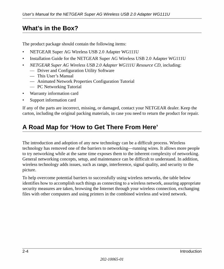
What’s in the Box?
The product package should contain the following items:
• NETGEAR Super AG Wireless USB 2.0 Adapter WG111U• Installation Guide for the NETGEAR Super AG Wireless USB 2.0 Adapter WG111U• NETGEAR Super AG Wireless USB 2.0 Adapter WG111U Resource CD, including:
— Driver and Configuration Utility Software— This User’s Manual— Animated Network Properties Configuration Tutorial— PC Networking Tutorial
• Warranty information card• Support information card
If any of the parts are incorrect, missing, or damaged, contact your NETGEAR dealer. Keep the carton, including the original packing materials, in case you need to return the product for repair.
A Road Map for ‘How to Get There From Here’
The introduction and adoption of any new technology can be a difficult process. Wireless technology has removed one of the barriers to networking—running wires. It allows more people to try networking while at the same time exposes them to the inherent complexity of networking. General networking concepts, setup, and maintenance can be difficult to understand. In addition, wireless technology adds issues, such as range, interference, signal quality, and security to the picture.
To help overcome potential barriers to successfully using wireless networks, the table below identifies how to accomplish such things as connecting to a wireless network, assuring appropriate security measures are taken, browsing the Internet through your wireless connection, exchanging files with other computers and using printers in the combined wireless and wired network.
2-4 Introduction
202-10065-01
User’s Manual for the NETGEAR Super AG Wireless USB 2.0 Adapter WG111U
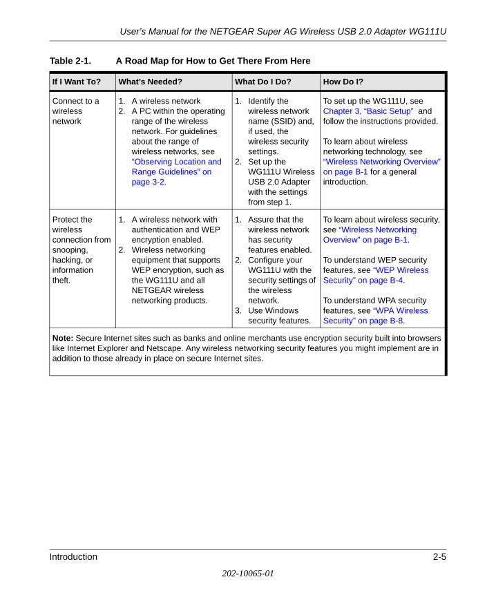
Table 2-1. A Road Map for How to Get There From Here
If I Want To? What’s Needed? What Do I Do? How Do I?
Connect to a wireless network
1. A wireless network2. A PC within the operating
range of the wireless network. For guidelines about the range of wireless networks, see “Observing Location and Range Guidelines” on page 3-2.
1. Identify the wireless network name (SSID) and, if used, the wireless security settings.
2. Set up the WG111U Wireless USB 2.0 Adapter with the settings from step 1.
To set up the WG111U, see Chapter 3, “Basic Setup” and follow the instructions provided.
To learn about wireless networking technology, see “Wireless Networking Overview” on page B-1 for a general introduction.
Protect the wireless connection from snooping, hacking, or information theft.
1. A wireless network with authentication and WEP encryption enabled.
2. Wireless networking equipment that supports WEP encryption, such as the WG111U and all NETGEAR wireless networking products.
1. Assure that the wireless network has security features enabled.
2. Configure your WG111U with the security settings of the wireless network.
3. Use Windows security features.
To learn about wireless security, see “Wireless Networking Overview” on page B-1.
To understand WEP security features, see “WEP Wireless Security” on page B-4.
To understand WPA security features, see “WPA Wireless Security” on page B-8.
Note: Secure Internet sites such as banks and online merchants use encryption security built into browsers like Internet Explorer and Netscape. Any wireless networking security features you might implement are in addition to those already in place on secure Internet sites.
Introduction 2-5
202-10065-01

User’s Manual for the NETGEAR Super AG Wireless USB 2.0 Adapter WG111U
Connect to the Internet over the wireless network.
1. An active Internet connection like those from cable or DSL service providers.
2. A wireless network connected to the cable or DSL Internet service through a cable/DSL router as illustrated in “Connecting to an Access Point in Infrastructure Mode” on page 4-2.
3. TCP/IP Internet networking software installed and configured on your PC according to the requirements of the Internet service provider.
4. A browser like Internet Explorer or Netscape Navigator.
1. Activate your wireless link and verify your network connection.
2. Open an Internet browser such as Internet Explorer or Netscape Navigator.
To configure your WG111U in Infrastructure Mode, see “Basic Installation Instructions” on page 3-4, and locate the section for your version of Windows.
For assistance with configuring the TCP/IP Internet software on a PC, see “Preparing Your Computers for TCP/IP Networking” on page C-4 or refer to the PC Networking Tutorial on the NETGEAR Super AG Wireless USB 2.0 Adapter WG111U Resource CD and the Help information provided in the Windows system you are using. .
Table 2-1. A Road Map for How to Get There From Here
If I Want To? What’s Needed? What Do I Do? How Do I?
2-6 Introduction
202-10065-01

User’s Manual for the NETGEAR Super AG Wireless USB 2.0 Adapter WG111U
Exchange files between a wirelessly connected PC and other computers in a combined wireless and wired network.
1. The PC you are using to connect to the wireless network needs to be configured with the Windows Client and File and Print Sharing.
2. The PC you are using to connect to the wireless network needs to be configured with the same Windows Workgroup or Domain settings as the other Windows computers in the combined wireless and wired network.
3. Any Windows networking security access rights such as login user name/ password that have been assigned in the Windows network or for sharing particular files must be provided when Windows prompts for such information.
4. If so-called Windows ‘peer’ Workgroup networking is being used, the drive, file system directory, or file need to be enabled for sharing.
1. Use the Windows Network Neighborhood feature to browse for computers in the combined wireless and wired network.
2. Browse the hard drive of the target computer in the network in order to locate the directory or files you want to work with.
3. Use the Windows Explorer copy and paste functions to exchange files between the computers.
For assistance with Windows networking software, see “Preparing Your Computers for TCP/IP Networking” on page C-4 for configuration scenarios or refer to the Help system included with your version of Windows.Windows Domain settings are usually managed by corporate computer support groups.Windows Workgroup settings are commonly managed by individuals who want to set up small networks in their homes, or small offices.For assistance with setting up Windows networking, refer to the PC Networking Tutorial on the NETGEAR Super AG Wireless USB 2.0 Adapter WG111U Resource CD and the Help information provided in the Windows system you are using.
Table 2-1. A Road Map for How to Get There From Here
If I Want To? What’s Needed? What Do I Do? How Do I?
Introduction 2-7
202-10065-01

User’s Manual for the NETGEAR Super AG Wireless USB 2.0 Adapter WG111U
Use printers in a combined wireless and wired network.
1. The PC you are using to connect to the wireless network needs to be configured with the Windows Client and File and Print Sharing.
2. The PC you are using to connect to the wireless network needs to be configured with the same Windows Workgroup or Domain settings as the other Windows computers in the combined wireless and wired network.
3. Any Windows networking security access rights such as login user name/ password that have been assigned in the Windows network must be provided when Windows prompts for such information.
4. If so-called Windows ‘peer’ networking is being used, the printer needs to be enabled for sharing.
1. Use the Windows Printers and Fax features to locate available printers in the combined wireless and wired network.
2. Use the Windows Add a Printer wizard to add access to a network printer from the PC you are using to wirelessly connect to the network.
3. From the File menu of an application such as Microsoft Word, use the Print Setup feature to direct your print output to the printer in the network.
Windows Domain settings are usually managed by corporate computer support groups.
Windows Workgroup settings are commonly managed by individuals who want to set up small networks in their homes, or small offices.
For assistance with setting up Windows networking, refer to the PC Networking Tutorial on the NETGEAR Super AG Wireless USB 2.0 Adapter WG111U Resource CD and the Help information provided in the Windows system you are using.
For assistance with setting up printers in Windows, refer to the Help and Support information that comes with the version of the Windows operating systems you are using.
Table 2-1. A Road Map for How to Get There From Here
If I Want To? What’s Needed? What Do I Do? How Do I?
2-8 Introduction
202-10065-01

Chapter 3 Basic Setup
This chapter describes how to install your NETGEAR Super AG Wireless USB 2.0 Adapter WG111U and set up basic wireless connectivity on your Wireless Local Area Network (WLAN). Advanced wireless network configuration is covered in Chapter 4, “Configuration” in this manual.
What You Need Before You Begin
You need to verify your computer meets the minimum system requirements and identify the wireless network configuration settings of the WLAN where you will connect before you can configure your wireless USB adapter and connect.
Verifying System RequirementsBefore installing the NETGEAR Super AG Wireless USB 2.0 Adapter WG111U, please make sure that these minimum requirements have been met:• You must have a PC with a Pentium® 300 MHz or higher compatible processor with an
available USB 2.0 or 1.1 port.
Note: If you do not have a USB 2.0 port on your PC, the throughput of the WG111U will be limited to the 12 Mbps of the USB 1.1 standard.
• A CD drive.• 5 MB of free hard disk space.
Note: Indoors, computers can easily connect to 802.11 wireless networks at distances of several hundred feet. Because walls do not always block wireless signals, others outside your immediate area could access your network. It is important to take appropriate steps to secure your network from unauthorized access. The NETGEAR Super AG Wireless USB 2.0 Adapter WG111U provides highly effective security features which are covered in “Understanding the Security Options” on page 5-1 in this manual. Deploy the security features appropriate to your needs.
Basic Setup 3-1
202-10065-01
User’s Manual for the NETGEAR Super AG Wireless USB 2.0 Adapter WG111U
• Windows XP Home, Windows XP Professional, Windows 2000, Windows ME, or Windows 98SE. Some versions of Windows may ask for the original Windows operating system installation files to complete the installation of the WG111U driver software.
Note: Some Windows XP systems may experience high CPU usage when using the WG111U. If this occurs, you should install Windows XP Service Pack 2 (SP2) or install the KB822603 Hot fix, which fixes the USB 2.0 Host controller driver issue.
http://www.microsoft.com/downloads/details.aspx?displaylang=en&FamilyID=733dd867-56a0-4956-b7fe-e85b688b7f86
Observing Location and Range GuidelinesComputers can connect over wireless networks indoors at a range which varies significantly based on the physical location of the computer with the NETGEAR Super AG Wireless USB 2.0 Adapter WG111U. For best results, avoid potential sources of interference, such as:
• Large metal surfaces• Microwaves• 2.4 GHz Cordless phones
In general, wireless devices can communicate through walls. However, if the walls are constructed with concrete, or have metal, or metal mesh, the effective range will decrease if such materials are between the devices.
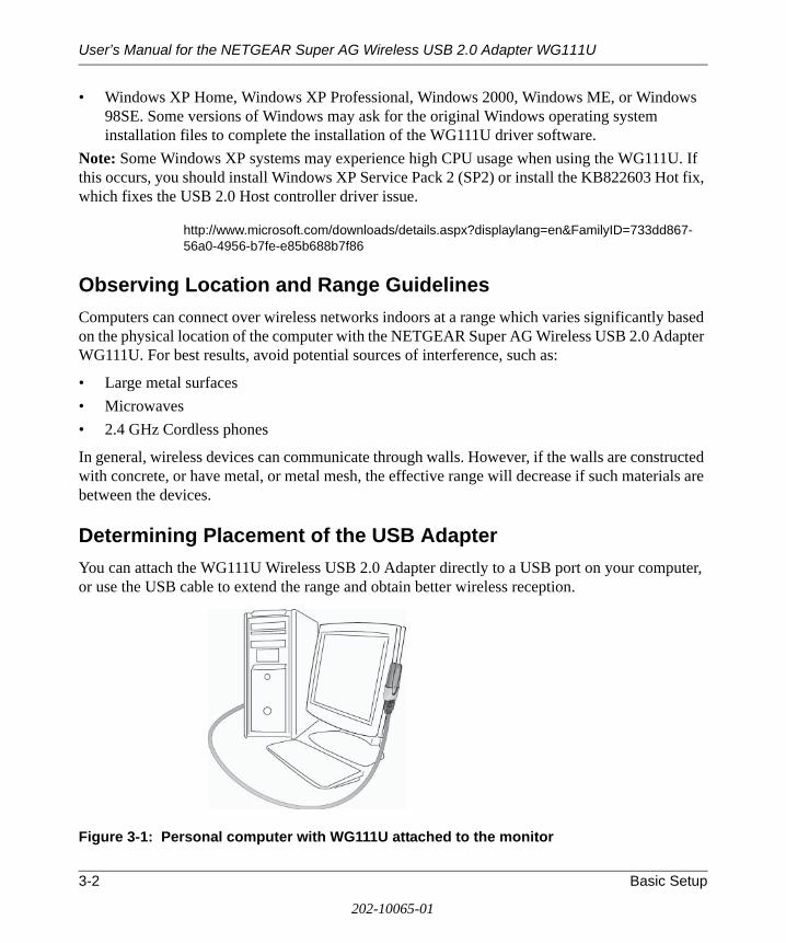
Determining Placement of the USB AdapterYou can attach the WG111U Wireless USB 2.0 Adapter directly to a USB port on your computer, or use the USB cable to extend the range and obtain better wireless reception.
Figure 3-1: Personal computer with WG111U attached to the monitor
3-2 Basic Setup
202-10065-01

User’s Manual for the NETGEAR Super AG Wireless USB 2.0 Adapter WG111U
Follow these instructions to use the USB cable, plastic cradle, and fasteners provided in the package for better USB Adapter placement on a notebook computer:
1. The WG111U Wireless USB 2.0 Adapter comes with three black fasteners. Locate the one that has a prickly side and attach it to the plastic cradle on the middle of the outside rear.
Figure 3-2: Attach fastener to back of plastic cradle
2. Insert the WG111U Wireless USB 2.0 Adapter in the plastic cradle.
3. Place one of the other black fasteners on the back of your notebook monitor near the top for better reception.
Note: If you are using the USB Adapter with a desktop PC, you can place the last fastener on the side of your desktop PC monitor nearest your wireless access point.
4. Join the black fasteners to attach the USB Adapter in the plastic cradle to the notebook or desktop monitor.
See the installation instructions for your operating system before attaching the USB cable to the USB Adapter and your computer.
Two Basic Operating Modes
The WG111U Wireless USB 2.0 Adapter can operate in the following two modes:
• Infrastructure Mode: An 802.11 networking framework in which devices and computers communicate with each other by first going through an access point (AP). For example, this mode is used when computers in a house connect to an Access Point that is attached to a router that lets multiple computers share a single cable or DSL broadband Internet connection.
• Ad-Hoc Mode: An 802.11 networking framework in which devices or computers communicate directly with each other, without the use of an AP. For example, Ad-Hoc Mode is used when two Windows computers are configured with file and print sharing enabled and you want to exchange files directly between them.
Basic Setup 3-3
202-10065-01

User’s Manual for the NETGEAR Super AG Wireless USB 2.0 Adapter WG111U
Both of these configuration options are available with the WG111U Wireless USB 2.0 Adapter. Infrastructure configuration procedures for basic network connectivity are covered below. Advanced infrastructure configuration procedures and ad-hoc configuration are covered in Chapter 4, “Configuration” of this manual.
WG111U Default Wireless Configuration Settings
If this is a new wireless network installation, use the factory default settings to set up the network and verify wireless connectivity. If this is an addition to an existing wireless network, you will need to identify the wireless configuration and security parameters already defined.
Your NETGEAR Super AG Wireless USB 2.0 Adapter WG111U factory default basic settings are:
• Network Name Service Set Identification (SSID): NETGEAR_11g
Note: In order for the WG111U Wireless USB 2.0 Adapter to communicate with a wireless access point or wireless adapter, all devices must be configured with the same wireless network name (SSID).
• Network Mode (Infrastructure or Ad-hoc): Infrastructure
• Data security WPA-PSK: Enabled, Passphrase: NETGEAR-ULTRA-G
The section below provides instructions for setting up the NETGEAR Super AG Wireless USB 2.0 Adapter WG111U for basic wireless connectivity to an access point. The procedures below provide step-by-step installation instructions for Windows PCs.
Basic Installation Instructions
Use the procedure below that corresponds to the version of Windows you are using:
• “For Windows XP Users Installing a WG111U” on page 3-5
• “For Windows 2000, ME, and 98SE Users Installing a WG111U” on page 3-9
3-4 Basic Setup
202-10065-01

User’s Manual for the NETGEAR Super AG Wireless USB 2.0 Adapter WG111U
For Windows XP Users Installing a WG111U
Install the WG111U driver and configuration utility software.
a. Power on your PC, let the operating system boot up completely, and log in as needed.
b. Insert the Resource CD for the WG111U into your CD drive. The CD main page shown at the right will load.
c. Click Install Driver and Utility.
Follow the InstallShield Wizard steps.
You will be prompted to choose the country you are located in. Select your location from the list.
d. Click Finish when done, and if prompted restart your computer.
WG111U Resource CD
Note: If this screen fails to load automatically, browse to the CD and double-click on autorun.exe.
InstallShield Wizard
Note: If a Windows XP Certification warning appears, click Continue Anyway to proceed.
Basic Setup 3-5
202-10065-01

User’s Manual for the NETGEAR Super AG Wireless USB 2.0 Adapter WG111U
Install the NETGEAR Super AG Wireless USB 2.0 Adapter WG111U.
a. Locate an available USB port on your PC. Connect the USB cable to the WG111U and insert the other end of the cable into the USB slot on your PC.
b. After a short delay, the Found New Hardware Wizard displays. The first time that you install the WG111U on a computer, the wizard will install the bootloader device. Follow the installation prompts.
Note: Click Continue Anyway if you are prompted with a Windows XP Logo testing message.
c. After the bootloader device is installed, the Found New Hardware Wizard displays again and installs the WG111U. Follow the installation prompts.
d. Next you will be prompted to enable the NETGEAR Smart Wireless Settings Utility configuration utility.
Click Yes to accept this option.
If you choose No, you must read the Windows XP documentation for an explanation of how to use the Windows XP wireless network configuration utility
e. Click Finish when done, and if prompted restart your computer. You will see the WG111U system tray icon on the lower right portion of the Windows task bar.
Add New Hardware Wizard
Note: If the USB port in your computer is not a USB v2.0 type port but rather a USB v1.1 type port, you will see a “HI_SPEED USB Device Plugged into non-HI-SPEED USB Hub” message. The WG111U will work but the USB v1.1 port maximum speed is 12 Mbps whereas the maximum speed of a USB v2.0 port is 480 Mbps. So, when the WG111U is connected to a USB v1.1 port, the communications speed will be limited to the maximum of the USB v1.1 port.
Note: Click Continue Anyway if you are prompted with a Windows XP Logo testing message.
Enable NETGEAR Utility Configuration
WG111U System Tray Icon
3-6 Basic Setup
202-10065-01
User’s Manual for the NETGEAR Super AG Wireless USB 2.0 Adapter WG111U
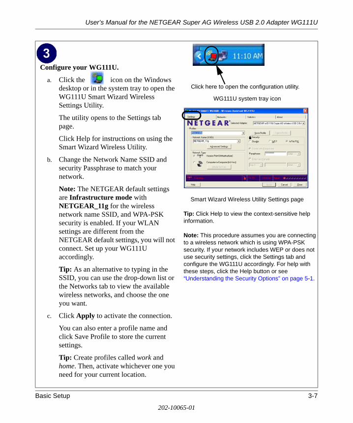
Configure your WG111U.
a. Click the icon on the Windows desktop or in the system tray to open the WG111U Smart Wizard Wireless Settings Utility.
The utility opens to the Settings tab page.
Click Help for instructions on using the Smart Wizard Wireless Utility.
b. Change the Network Name SSID and security Passphrase to match your network.
Note: The NETGEAR default settings are Infrastructure mode with NETGEAR_11g for the wireless network name SSID, and WPA-PSK security is enabled. If your WLAN settings are different from the NETGEAR default settings, you will not connect. Set up your WG111U accordingly.
Tip: As an alternative to typing in the SSID, you can use the drop-down list or the Networks tab to view the available wireless networks, and choose the one you want.
c. Click Apply to activate the connection.
You can also enter a profile name and click Save Profile to store the current settings.
Tip: Create profiles called work and home. Then, activate whichever one you need for your current location.
WG111U system tray icon
Smart Wizard Wireless Utility Settings page
Tip: Click Help to view the context-sensitive help information.
Note: This procedure assumes you are connecting to a wireless network which is using WPA-PSK security. If your network includes WEP or does not use security settings, click the Settings tab and configure the WG111U accordingly. For help with these steps, click the Help button or see “Understanding the Security Options” on page 5-1.
Click here to open the configuration utility.
Basic Setup 3-7
202-10065-01
User’s Manual for the NETGEAR Super AG Wireless USB 2.0 Adapter WG111U
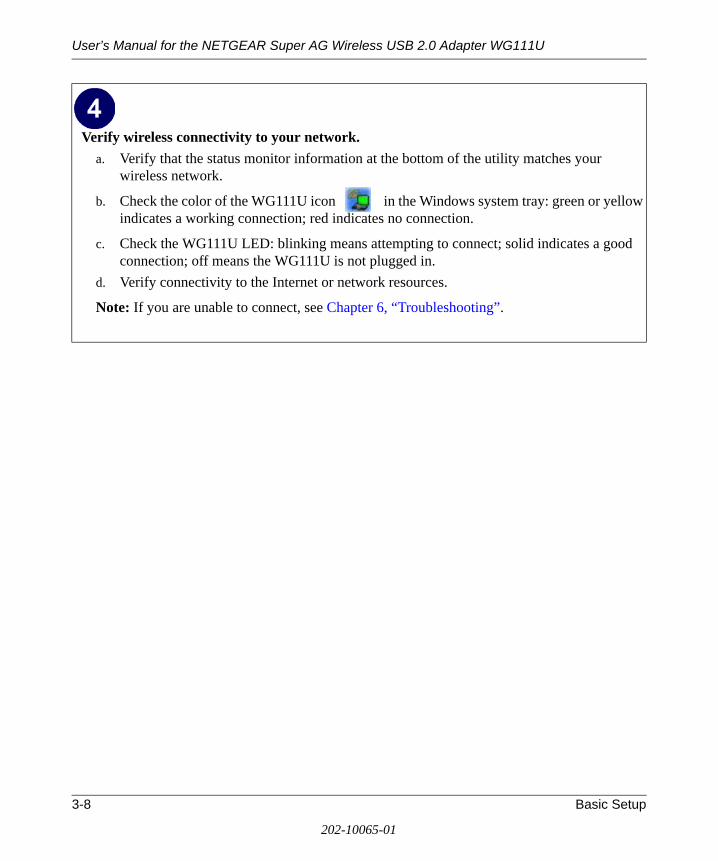
Verify wireless connectivity to your network.a. Verify that the status monitor information at the bottom of the utility matches your
wireless network.
b. Check the color of the WG111U icon in the Windows system tray: green or yellow indicates a working connection; red indicates no connection.
c. Check the WG111U LED: blinking means attempting to connect; solid indicates a good connection; off means the WG111U is not plugged in.
d. Verify connectivity to the Internet or network resources.
Note: If you are unable to connect, see Chapter 6, “Troubleshooting”.
3-8 Basic Setup
202-10065-01

User’s Manual for the NETGEAR Super AG Wireless USB 2.0 Adapter WG111U
For Windows 2000, ME, and 98SE Users Installing a WG111U
Install the WG111U driver and configuration utility software.
Note: Windows 2000 may require you to be logged on with administrator rights.
a. Power on your PC, let the operating system boot up completely, and log in as needed.
b. Insert the Resource CD for the WG111U into your CD drive. The CD main page shown at the right will load.
c. Click Install Driver and Utility.
Follow the InstallShield Wizard steps.
You will be prompted to choose the country you are located in. Select your location from the list.
d. Click Finish when done, and if prompted restart your computer.
WG111U Resource CD
Note: If this screen fails to load automatically, browse to the CD and double-click on autorun.exe.
InstallShield Wizard
Note: If a Windows 2000 Digital Signature warning appears, click Yes to proceed.
Basic Setup 3-9
202-10065-01

User’s Manual for the NETGEAR Super AG Wireless USB 2.0 Adapter WG111U
Install the NETGEAR Super AG Wireless USB 2.0 Adapter WG111U.
a. Locate an available USB port on your PC. Connect the USB cable to the WG111U and insert the other end of the cable into the USB slot on your PC.
b. After a short delay, the Found New Hardware Wizard displays. The first time that you install the WG111U on a computer, the wizard will install the bootloader device. Follow the installation prompts.
Note: Click Yes if you are prompted with a Digital Signature Not Found message.
c. After the bootloader device is installed, the Found New Hardware Wizard will display again and install the WG111U. Follow the installation prompts.
Note: Click Yes if you are prompted with a Digital Signature Not Found message.
d. Click Finish when done, and if prompted restart your computer.
You will see the WG111U system tray icon on the lower right portion of the Windows task bar.
Found New Hardware Wizard
Note: If your computer does not have a USB v2.0 port but rather a USB v1.1 type port, the WG111U will be limited to the maximum speed of the USB v1.1 port. USB v1.1 port maximum speed is 12 Mbps whereas the maximum speed of a USB v2.0 port is 480 Mbps.
WG111U System Tray Icon
3-10 Basic Setup
202-10065-01

User’s Manual for the NETGEAR Super AG Wireless USB 2.0 Adapter WG111U
Configure your WG111U.
a. Click on the WG111U icon on the Windows desktop or in the system tray to open the WG111U configuration utility.
The utility opens to the Settings tab page.
Click Help for instructions on using the Smart Wizard Wireless Utility.
b. Change the Network Name SSID and security Passphrase to match your network.
Note: The NETGEAR default settings are Infrastructure mode with NETGEAR_11g for the wireless network name SSID, and WPA-PSK security enabled. If your WLAN settings are different from the NETGEAR default settings, you will not connect. Set up your WG111U accordingly.
Tip: As an alternative to typing in the SSID, you can use the drop-down list or the Networks tab to choose from the available wireless networks.
c. Click Apply to activate the connection.
d. You can also enter a profile name and click Save Profile to store the current settings.
Tip: If you use your desktop PC to connect to a wireless network at work and at home, create profiles called work and home. Then, activate whichever one you need for wherever you are located.
WG111U system tray icon
WG111U Configuration Utility
Tip: Click Help to view the context-sensitive help information.
Note: This procedure assumes you are connecting to a wireless network which is using WPA-PSK security. If your network includes WEP or does not use security settings, click the Settings tab and configure the WG111U accordingly. For help with these steps, click the Help button or see “Understanding the Security Options” on page 5-1.
Click here to open the configuration utility.
Basic Setup 3-11
202-10065-01

User’s Manual for the NETGEAR Super AG Wireless USB 2.0 Adapter WG111U
WG111U Wireless Connection Indicators
The NETGEAR Super AG Wireless USB 2.0 Adapter WG111U provides the following indicators, which give you feedback on the status of your wireless connection:
• The status LED on the NETGEAR Super AG Wireless USB 2.0 Adapter WG111U indicates the condition of wireless link.
• The color of the SysTray icon is on the System Tray portion of the taskbar in the Microsoft Windows desktop indicates the status of the connection.
Verify wireless connectivity to your network.
a. Verify that the status monitor information at the bottom of the utility matches your wireless network.
b. Check the color of the WG111U icon in the Windows system tray: green or yellow indicates a working connection; red indicates no connection.
c. Check the WG111U LED: blinking means attempting to connect; solid indicates a good connection; off means the WG111U is not plugged in.
d. Verify connectivity to the Internet or network resources.
Note: If you are unable to connect, see Chapter 6, “Troubleshooting”.
3-12 Basic Setup
202-10065-01

User’s Manual for the NETGEAR Super AG Wireless USB 2.0 Adapter WG111U
Interpreting the LED on the WG111U
The status LED is described in this table.
Table 3-1: LED Descriptions
LED Meaning
OFF • The WG111U in not plugged in to the PC.• Power save mode (default from power up or reset).
Blink Looking for network association.
On Associated or joined with network.
Status LED
Basic Setup 3-13
202-10065-01

User’s Manual for the NETGEAR Super AG Wireless USB 2.0 Adapter WG111U
Interpreting System Tray Icon ColorsThe System Tray (SysTray) resides on one end of the taskbar in the Microsoft Windows desktop.
Color Condition DescriptionRed The WG111U has no
connection to any wireless node.
The WG111U is not able to link to any other wireless node or the link is lost. Check your configuration or try moving to a location where the wireless signal quality is better.
Yellow The WG111U has a connection with another wireless node.
The wireless link is weak. You may need to move to a better spot, such as closer to the wireless access point. Also, look for possible interference such as a 2.4 GHz cordless phone or large metal surface.
Green The WG111U has a connection with another wireless node.
The WG111U has established good communication with an access point and the signal quality is strong.
3-14 Basic Setup
202-10065-01

Chapter 4 Configuration
This chapter describes how to configure your NETGEAR Super AG Wireless USB 2.0 Adapter WG111U for wireless connectivity on your Wireless Local Area Network (WLAN) and use the data security encryption features.
Understanding the Configuration Options
The WG111U configuration utility provides a complete and easy to use set of tools to:
• Configure wireless settings.
• Monitor wireless network connections.
• Save your settings in configuration profiles.
The section below introduces these capabilities of the configuration utility.
Using Configuration Profiles
The WG111U configuration utility uses profiles to store all the configuration settings for a particular wireless network. You can store multiple profiles and recall the one which matches the network you want to join.
Note: The instructions in this section refer to the NETGEAR WG111U configuration utility. For Windows XP users to use the NETGEAR configuration utility, the Windows XP configuration utility must be deselected. If you did not enable the NETGEAR utility when you installed the WG111U Wireless USB 2.0 Adapter, open the network connections from the system tray icon, click the Properties button, click the Wireless Networks tab and then clear the “Use Windows to configure my wireless network settings” check box.
Configuration 4-1
202-10065-01

User’s Manual for the NETGEAR Super AG Wireless USB 2.0 Adapter WG111U
For example, if you use your notebook PC to connect to a wireless network in an office and a wireless network in your home, you can create a profile for each wireless network. Then, you can easily load the profile that has all the configuration settings you need to join the network you are using at the time.
There are two types of wireless network connections you can configure:
• Infrastructure Mode — uses the 802.11 infrastructure mode.
• Ad-hoc Mode — uses the 802.11 ad-hoc mode.
For more information on 802.11 wireless network modes, see “Wireless Networking Overview” on page B-1 of this manual.
Connecting to an Access Point in Infrastructure ModeThis section provides instructions for configuring the NETGEAR Super AG Wireless USB 2.0 Adapter WG111U to connect to a wireless access point.
How to Configure an Infrastructure Mode ProfileFollow the instructions below to configure an infrastructure mode profile for connecting to an access point.1. Run the WG111U Smart Wireless Wizard.
a. Make sure the WG111U software is installed and the WG111U is connected to your PC.
b. Open the configuration utility by clicking on the WG111U icon in the Windows system tray. The Settings page appears, as shown below.
4-2 Configuration
202-10065-01
User’s Manual for the NETGEAR Super AG Wireless USB 2.0 Adapter WG111U
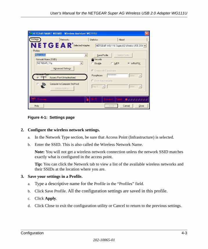
Figure 4-1: Settings page
2. Configure the wireless network settings.
a. In the Network Type section, be sure that Access Point (Infrastructure) is selected.
b. Enter the SSID. This is also called the Wireless Network Name.
Note: You will not get a wireless network connection unless the network SSID matches exactly what is configured in the access point.
Tip: You can click the Network tab to view a list of the available wireless networks and their SSIDs at the location where you are.
3. Save your settings in a Profile.
a. Type a descriptive name for the Profile in the “Profiles” field.
b. Click Save Profile. All the configuration settings are saved in this profile.c. Click Apply.
d. Click Close to exit the configuration utility or Cancel to return to the previous settings.
Configuration 4-3
202-10065-01

User’s Manual for the NETGEAR Super AG Wireless USB 2.0 Adapter WG111U
4. Verify wireless connectivity to your network.
Verify connectivity by using a browser such as Netscape or Internet Explorer to connect to the Internet, or check for file and printer access on your network.
You can check the status bar in the configuration utility for the current connection status.
Note: If you cannot connect, see Chapter 6, “Troubleshooting”. Also, for problems with accessing network resources, the Windows Client and File and Print Sharing software might not be installed and configured properly on your computers. Please refer to “Preparing Your Computers for TCP/IP Networking” on page C-4.
Connecting to Another PC in Ad-hoc Mode
The peer-to-peer setting of the WG111U uses Ad-Hoc mode. Ad-Hoc mode is an 802.11 networking framework in which devices or computers communicate directly with each other, without the use of an access point. For example, this mode is used when two Windows computers are configured with file and print sharing enabled and you want to exchange files directly between them.
How to Configure an Ad-hoc Mode ProfileNote: Ad-hoc mode will not work using DHCP settings. Ad-hoc mode requires static IP addresses (such as 192.168.0.1). For instructions on setting up static IP addresses on a Windows PC, refer to the PC Networking Tutorial included on the NETGEAR Super AG Wireless USB 2.0 Adapter WG111U Resource CD.
Follow the instructions below to configure an Ad-hoc mode profile.
1. Configure the PC network settings.
a. Configure each PC with a static IP address or with the IPX protocol.
Note: For instructions on configuring static IP addresses, refer to the networking tutorial on your NETGEAR Super AG Wireless USB 2.0 Adapter WG111U Resource CD.
b. Restart the PCs.
2. Run the WG111U Smart Wireless Wizard.
a. Make sure the WG111U software is installed and the WG111U is connected to your PC.
b. Open the configuration utility by clicking on the WG111U icon on the Windows desktop or in the system tray. The Settings page opens.
4-4 Configuration
202-10065-01

User’s Manual for the NETGEAR Super AG Wireless USB 2.0 Adapter WG111U
Figure 4-2: Settings page
c. Select Computer-to-Computer (Ad-Hoc) for the Network Type. Enter the SSID for the Ad-Hoc network.
d. Click Initiate Ad-Hoc. The Ad-Hoc Setting dialog box appears.
Figure 4-3: Ad-Hoc Setting dialog box
— In the Start Ad-Hoc field, choose the wireless standard (802.11a, 802.11b, or 802.11g) for your Ad-Hoc computer-to-computer network.
— In the Channel field, Automatic should work. If you notice interference problems with another nearby wireless device, select a channel that is not being used by any other wireless networks near your wireless adapter. Use the Networks page to identify the channels in use in your area.
Configuration 4-5
202-10065-01
User’s Manual for the NETGEAR Super AG Wireless USB 2.0 Adapter WG111U
Note: The channel number differs depending on the country. The connection speed automatically defaults to the highest speed.
e. Click OK. The WG111U will scan the area to determine which channel to use.
f. Click Apply.
3. Save your settings in a Profile.
a. Type a descriptive name in the “Profiles” field.
b. Click Save Profile. All the configuration settings are saved in this profile.
c. Click Apply.
d. Click Close to exit the configuration utility.
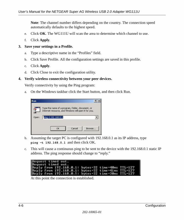
4. Verify wireless connectivity between your peer devices.
Verify connectivity by using the Ping program:
a. On the Windows taskbar click the Start button, and then click Run.
b. Assuming the target PC is configured with 192.168.0.1 as its IP address, type ping -t 192.168.0.1 and then click OK.
c. This will cause a continuous ping to be sent to the device with the 192.168.0.1 static IP address. The ping response should change to “reply.”
At this point the connection is established.
4-6 Configuration
202-10065-01

User’s Manual for the NETGEAR Super AG Wireless USB 2.0 Adapter WG111U
Note: If you cannot connect, see the Chapter 6, “Troubleshooting”. Also, for problems with accessing network resources, the Windows Client and File and Print Sharing software might not be installed and configured properly on your computers. Please refer to “Preparing Your Computers for TCP/IP Networking” on page C-4.
What’s on the Statistics Page?
The Statistics page provides real time and historical trend information on the data traffic and performance of your wireless adapter. The Statistics page is displayed below:
Figure 4-4: Statistics page
• Transmit/Receive Performance (%): A real-time graph identifying the total, receive, and transmit utilization as a percentage the total possible.
• Total/Receive/Transmit Graph: Identifies the trend of transmit/receive data communications over time.
• Transmit Statistics: Identifies transmit megabits per second (Mbps), transmit packets per second (Tx Packets/s), total transmitted packets, and transmit errors.
• Receive Statistics: Identifies receive megabits per second (Mbps), receive packets per second (Rx Packets/s), total received packets, and received errors.
Configuration 4-7
202-10065-01
User’s Manual for the NETGEAR Super AG Wireless USB 2.0 Adapter WG111U
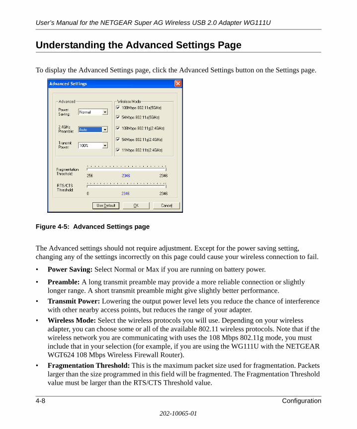
Understanding the Advanced Settings Page
To display the Advanced Settings page, click the Advanced Settings button on the Settings page.
Figure 4-5: Advanced Settings page
The Advanced settings should not require adjustment. Except for the power saving setting, changing any of the settings incorrectly on this page could cause your wireless connection to fail.
• Power Saving: Select Normal or Max if you are running on battery power.
• Preamble: A long transmit preamble may provide a more reliable connection or slightly longer range. A short transmit preamble might give slightly better performance.
• Transmit Power: Lowering the output power level lets you reduce the chance of interference with other nearby access points, but reduces the range of your adapter.
• Wireless Mode: Select the wireless protocols you will use. Depending on your wireless adapter, you can choose some or all of the available 802.11 wireless protocols. Note that if the wireless network you are communicating with uses the 108 Mbps 802.11g mode, you must include that in your selection (for example, if you are using the WG111U with the NETGEAR WGT624 108 Mbps Wireless Firewall Router).
• Fragmentation Threshold: This is the maximum packet size used for fragmentation. Packets larger than the size programmed in this field will be fragmented. The Fragmentation Threshold value must be larger than the RTS/CTS Threshold value.
4-8 Configuration
202-10065-01
User’s Manual for the NETGEAR Super AG Wireless USB 2.0 Adapter WG111U
• RTS/CTS Threshold: RTS is request to send and CTS is clear to send; their purpose is to avoid collisions. RTS/CTS will be enabled if the data frame size is larger than the threshold value set here. The maximum frame size is 2346 octets, so if the threshold is 2346, RTS/CTS will be disabled.
Note: This setting is reserved for wireless testing and advanced configuration only. Do not change this setting unless you are sure you need to. The primary reason for implementing RTS/CTS is to minimize collisions between hidden stations. This occurs when users and access points are spread out and a high number of retransmissions occur on the wireless LAN.
European Regulatory Requirements for Transmit Power Control
Follow the instructions below only if you are operating in Europe and want to use the Advanced 802.11a 5 GHz settings of the WG111U.
Note: If you are not operating in Europe or do not want to use the Advanced 802.11 a settings, continue on to Chapter 5, “Wireless Security Configuration”.
TPC Configuration Procedure
The end user is obligated to follow the procedure below in order to operate this device in accordance with European regulatory requirements for Transmit Power control. The TPC feature implemented in this Wireless LAN device must be configured by the end user when operating in any European Community country.
The Wireless LAN Adapter includes a transmit power adjustment found in the Advanced Settings section under the Settings page of the Client Utility. The Transmit Power Level pull-down list includes the following settings: 100%, 50%, 25%, 12.5%, Lowest. The default setting is 100%, which represents no reduction in power. The following procedure verifies whether a reduction to 50% or 25% should be set:
1. Check the current link rate:
a. When connected to your Wireless Infrastructure (home, corporate or public Wireless network), use the NETGEAR WG111U Smart Wizard Wireless Assistant to check that a connection is established.
b. Check current transmit & receive link rates by viewing the status line at the bottom of the Smart Wizard Wireless Assistant screen. The highest possible link rate is 54Mbps. Note the current value.
2. Check whether the maximum link rate is currently achieved. If the current link rate found in step 1 is...
Configuration 4-9
202-10065-01

User’s Manual for the NETGEAR Super AG Wireless USB 2.0 Adapter WG111U
— lower than the maximum possible link rate value of 54Mbps, then no further action is required.
OR
— equal to the maximum possible link rate of 54Mbps, then a reduction in the wireless adapter's transmit power may be possible. Proceed to the next step.
3. Reduce power to 50% and recheck the link rate.
a. Select the Advanced Settings button on the Settings page.
b. Under the Transmit Power pull-down list, choose the 50% setting and click OK to save this value. The network connection will be temporarily disconnected and then re-established.
c. Check the current link rate using the Client Utility as explained in step 1. If the link rate value using the 50% setting is now...
— lower than the maximum possible value of 54 Mbps, then the 50% power reduction is not necessary. Change the Transmit Power Level setting back to 100%. No further action is required.
— OR
— equal to the maximum possible link rate value of 54 Mbps, then the 50% reduction has no adverse affect on operation and further reduction may be needed. Proceed to the next step.
4. Reduce the power to 25% and recheck the link rate.
a. Repeat step 3 using a Transmit Power Level of 25%.
b. Check if link rate is decreased from the maximum possible value. If the link rate value using the 25% setting is now...
— lower than the maximum possible value of 54 Mbps, then the 25% power reduction is not necessary. Change the Transmit Power Level setting back to 50% as explained in step 3. No further action is required.
— OR
— equal to the maximum possible link rate value of 54 Mbps, then the 25% reduction has no adverse affect on operation and further reduction is not necessary. Retain the 25% setting. No further action is required.
Note: The above procedure should be repeated when relocating the wireless adapter within the current wireless network or to a wireless network in a new location.
4-10 Configuration
202-10065-01

Chapter 5 Wireless Security Configuration
This chapter describes how to configure the security features of your NETGEAR Super AG Wireless USB 2.0 Adapter WG111U.
Understanding the Security Options
For a full discussion of wireless security technologies, please see “Wireless Networking Overview” on page B-1. The WG111U configuration utility provides the following security options:
• WEPWired Equivalent Privacy is an existing, widely implemented and supported, data encryption protocol for 802.11 wireless networks. All wireless nodes on the network are configured with a static 64-bit or 128-bit Shared Key for data encryption but authentication is optional.
• WPA-PSKWPA Pre-Shared Key (WPA-PSK) performs authentication and strong data encryption that includes dynamic key generation based on a pre-shared key. WPA-PSK does not need RADIUS or certificate servers.
When you use the WG111U configuration utility to configure these security options, you can save your settings in a profile. For example, if you use WPA-PSK at work but WEP at home, you can have work and home profiles that make it easy to switch from one environment to the other. For more information on configuring profiles, see “Using Configuration Profiles” on page 4-1.
Note: The instructions in this section refer to the NETGEAR WG111U configuration utility. For Windows XP users to use the NETGEAR configuration utility, the Windows XP configuration utility must be deselected. If you did not enable the NETGEAR utility when you installed the WG111U Wireless USB 2.0 Adapter, open the network connections from the system tray icon, click the Properties button, click the Wireless Networks tab and then clear the “Use Windows to configure my wireless network settings” check box.
Wireless Security Configuration 5-1
202-10065-01
User’s Manual for the NETGEAR Super AG Wireless USB 2.0 Adapter WG111U
Using WEP Security
You can strengthen the security of your wireless connection by enabling Wired Equivalent Privacy (WEP) encryption of the wireless data communications. For more information on 802.11 wireless security, see “Wireless Networking Overview” on page B-1.
In addition to the WG111U wireless security features, configure appropriate LAN network security features such as requiring a user name and password to access shared resources in your network.
Basic Requirements for WEPWEP requires these elements:
1. A wireless adapter with WEP enabled.
2. A wireless access point or another PC with WEP enabled.
Fill in the worksheet and use the procedures below to configure the WEP encryption settings of your WG111U.
5-2 Wireless Security Configuration
202-10065-01

User’s Manual for the NETGEAR Super AG Wireless USB 2.0 Adapter WG111U
WEP Security Settings WorksheetPrint this form, fill in the configuration parameters and put it in a safe place for possible future reference. For an existing wireless network, the person who set up the network will be able to provide this information.
• Wireless Network Name (SSID)
The Service Set Identification (SSID) identifies the wireless local area network. For the access point and wireless nodes to communicate with each other, all must be configured with the same SSID.
Note: Some wireless access points will not broadcast their SSID as a security feature. In such a case, you will need to get the SSID from the wireless network administrator.
Wireless network name (SSID): ______________________________
• WEP Security Encryption Key
The default WEP encryption key number is 1, and the default key size is 64 bits.
Note: The key number as well as the key value used by all wireless nodes must be the same. If yours is different, you will not be able to connect.
WEP Encryption Key Size, circle one: 64 or 128 bit
WEP Encryption Passphrase (case sensitive), if used: ____________________________
A Passphrase is used to automatically generate the WEP hexadecimal numbers for the key. If the wireless network Access Point uses a Passphrase, you can also use that here. Otherwise, you will have to manually enter the hexadecimal numbers.
Note: Not all wireless networks support the Passphrase method of key generation. In such settings, instead of Passphrase, use the Enter Key Manually option.
WEP Hexadecimal Numbers (not case sensitive): ______________________________
— 64-bit WEP: enter 10 hexadecimal digits (any combination of 0-9, a-f, or A-F).
— 128-bit WEP: enter 26 hexadecimal digits (any combination of 0-9, a-f, or A-F).
Use the procedures below to configure WEP security settings in the WG111U.
Wireless Security Configuration 5-3
202-10065-01

User’s Manual for the NETGEAR Super AG Wireless USB 2.0 Adapter WG111U
How to Configure WEP Encryption SecurityFollow the steps below to configure WEP Encryption Security.
1. Run the WG111U Smart Wireless Wizard.
a. Make sure the WG111U software is installed and the WG111U is fully inserted in the USB port of your PC.
b. Open the configuration utility by clicking on the WG111U icon on the Windows desktop or in the system tray. The Settings page opens.
2. Configure the Network Name (SSID) settings.
Enter the SSID. This is also called the Wireless Network Name.
Tip: Click the Networks tab to view a list of the available wireless networks and their SSIDs.
3. Configure the WEP settings.
a. Select the WEP radio button.
Figure 5-1: WEP settings screen
5-4 Wireless Security Configuration
202-10065-01
User’s Manual for the NETGEAR Super AG Wireless USB 2.0 Adapter WG111U
b. Select how you will enter the Key and the key size. The choices are:
• Create Key with Passphrase. The characters are case sensitive. • Enter Key Manually
Select the encryption strength choices are:
• 64-bit WEP data encryption • 128-bit WEP data encryption
Note: Larger encryption keys require more processing and may slow the communications response times, and consume more notebook PC battery power.
c. Select the Key number: The Key setting must match what is set in wireless network.
d. Click Apply for the changes to take effect. In the status area at the bottom of the screen, you will notice the security lock icon change from open and red to closed and yellow.
4. Save your settings in a Profile.
a. Type a descriptive name in the Profiles field.
b. Click Save Profile. All the configuration settings are saved in this profile.
c. Click Apply and click Close to exit the configuration utility.
Using WPA-PSK Advanced Security
You can have very strong security on your wireless connection by enabling WPA-PSK. For more information on wireless security, see “Wireless Networking Overview” on page B-1.
Basic Requirements for WPA-PSKWPA-PSK requires these elements:
1. A WPA-PSK enabled wireless adapter with WPA client software such as the WG111U.2. A WPA-PSK enabled wireless access point or router with built-in WPA enabled access point.
Fill in the worksheet and use the procedure below to configure WPA-PSK settings.
Wireless Security Configuration 5-5
202-10065-01

User’s Manual for the NETGEAR Super AG Wireless USB 2.0 Adapter WG111U
WPA-PSK Security Settings WorksheetPrint this form, fill in the configuration parameters and put it in a safe place for possible future reference. For an existing wireless network, the person who set up the network will be able to provide this information.
• Wireless Network Name (SSID)
The Service Set Identification (SSID) identifies the wireless local area network.
Note: Some wireless access points will not broadcast their SSID as a security feature. In such a case, you will need to get the SSID from the wireless network administrator.
Wireless network name (SSID): ______________________________
• Passphrase (Pre-Shared Key): ________________________________________
How to Configure WPA-PSK Advanced SecurityFollow the steps below to configure WPA-PSK Advanced Security.
1. Run the WG111U Smart Wireless Wizard.
a. Make sure the WG111U software is installed and the WG111U is fully inserted in the USB port of your PC.
b. Open the configuration utility by clicking on the WG111U icon on the Windows desktop or in the system tray. The Settings page opens.
2. Configure the Network Name (SSID) settings.
Enter the SSID. This is also called the Wireless Network Name.
Tip: Click the Networks tab to view a list of the available wireless networks and their SSIDs.
5-6 Wireless Security Configuration
202-10065-01

User’s Manual for the NETGEAR Super AG Wireless USB 2.0 Adapter WG111U
3. Configure the WPA-PSK settings.
a. Under Security, select the WPA-PSK radio button.
Figure 5-2: WPA-PSK settings screen
b. Enter the Passphrase (Pre-Shared Key).
c. Click Apply for the changes to take effect. In the status area at the bottom of the screen, you will notice the security lock icon change from open and red to closed and yellow.
4. Save your settings in a Profile.
a. Type a descriptive name in the Profiles field.
b. Click Save Profile. All the configuration settings are saved in this profile.
c. Click Apply and click Close to exit the configuration utility.
Wireless Security Configuration 5-7
202-10065-01

User’s Manual for the NETGEAR Super AG Wireless USB 2.0 Adapter WG111U
5-8 Wireless Security Configuration
202-10065-01

Chapter 6 Troubleshooting
This chapter provides information about troubleshooting your NETGEAR Super AG Wireless USB 2.0 Adapter WG111U. After each problem description, instructions are given to help you diagnose and solve the problem.
Also, for problems with accessing network resources, the Windows software might not be installed and configured properly on your computers. Please refer to Appendix C, “Preparing Your Network to Work with a Router”.
Basic Tips
If you have problems connecting to your wireless network, try the tips below.
Symptom Cause SolutionThe LED is not lit. The WG111U is not
connected to the USB port properly or the WG111U software is not loaded.
Remove and reinsert the WG111U.Check the Windows device manager to see if the WG111U is recognized and enabled. Reload the WG111U software, if necessary.Try to install the WG111U in a different USB slot on your system if one is available.
The wireless LED blinks and cannot connect to an access point.
The WG111U is attempting to connect to an access point, but cannot connect.
The access point may not be powered on. Or, the access point and the WG111U are not configured with the same wireless parameters. Check the SSID and WEP settings.
I can connect to an access point, but I cannot connect to other computers on the network or the Internet.
This could be a physical layer problem or a network configuration problem.
Check to make sure that the access point is physically connected to the Ethernet network.Make sure that the IP addresses and the Windows networking parameters are all configured correctly.Restart the cable or DSL modem, router, access point, and notebook PC.Refer to “A Road Map for ‘How to Get There From Here’” on page 2-4 for additional suggestions.
Troubleshooting 6-1
202-10065-01

User’s Manual for the NETGEAR Super AG Wireless USB 2.0 Adapter WG111U
Frequently Asked Questions
Use the information below to solve common problems you may encounter. Also, please refer to the knowledge base on the NETGEAR web site at http://ww.netgear.com/support/main.asp.
General Questions
Why do I see no more than 54 Mbps on the Configuration Utility status line?The WG111U can operate at 108 Mbps. You are probably connecting to a standard 802.11g network. If you use the NETGEAR WGT624 108 Mbps Wireless Firewall Router or WG634U 108 Mbps Wireless Media Router, you will see network speeds up to 108 Mbps.
If you are connecting to an 802.11b network, the maximum 802.11b speed is 11 Mbps.
If your computer does not have a USB v2.0 port but rather a USB v1.1 type port, the WG111U will be limited to the maximum speed of the USB v1.1 port. USB v1.1 port maximum speed is 12 Mbps whereas the maximum speed of a USB v2.0 port is 480 Mbps. PC computers can be upgraded with optional add-on USB v2.0 adapters that provide one or more USB v2.0 ports.
If you are already using a USB 2.0 controller, make sure that you are using the correct driver for USB 2.0.For Windows XP, you need to upgrade your system to Service Pack 1 in order to utilize the USB 2.0 port. For Windows 2000, you need to upgrade your system to Service Pack 4 in order to utilize the USB 2.0 port.
The WG111U Smart Configuration Utility keeps asking me to save my settingsThis is because you have made changes to the settings and the utility is offering you the chance to save the changes. If you want to avoid these Profile setting prompts, simply click Apply before you close the utility program.
Ad Hoc mode is not working correctlyYou need to click the Initiate Ad Hoc button on the Settings screen before you click Apply. Here is how you start an Ad Hoc network:
1. Fill in the Network Name (SSID).
2. Select the Computer-to-Computer (Ad Hoc) Network Type.
3. Click Initiate Ad Hoc.
4. Accept the default settings or make your changes and click OK.
6-2 Troubleshooting
202-10065-01

User’s Manual for the NETGEAR Super AG Wireless USB 2.0 Adapter WG111U
5. Click Apply.
Note: Be sure all computers in your Ad Hoc network are configured with static IP addresses in the same subnet.
How to know if the WG111U card has received a valid IP addressThe easiest way is find out if the WG111U card has received a valid IP address from the Wireless Router/AP is to open up the WG111U utility program and check the IP address in the About page.
How to use XP’s own Wireless configuration utilityThe NETGEAR WG111U software is designed so that the user will be asked to choose one of the utility programs during initial software installation. Be sure the WG111U is connected to the PC and follow these instructions to change your selection.
1. Go to Control Panel and select Network Connections.
2. Right click on the connection and select Properties.
3. Click the Wireless Networks tab.
4. Select or clear the WG111U “Use Windows to configure my wireless network settings” check box.
I cannot connect to the AP that I want from the Networks browser listThe access point is available and there is good signal strength. There are a few possibilities:
• If the access point (AP) is WPA-PSK protected, you will need to have the correct WPA-PSK Passphrase. Otherwise, the WG111U will still be connected to the previous access point and you will not be able to change to the WPA-PSK access point.
• If the access point is WEP protected (either 64 or 128 bit encryption), you will be prompted to enter the WEP encryption security information.
New Hardware Wizard appears after installation has completedThis happens if the USB device is connected to a different port than the one used during installation. Return the USB device to the original USB port.
How to get a PDF copy of the ManualIn the Manual HTML page, there is a PDF button image at the top right hand corner of the web page. Click the PDF icon to bring up a PDF file of the entire manual. You can also Print, Email, or Bookmark pages using the corresponding icons next to the PDF icon.
Troubleshooting 6-3
202-10065-01

User’s Manual for the NETGEAR Super AG Wireless USB 2.0 Adapter WG111U
6-4 Troubleshooting
202-10065-01

Appendix A Technical Specifications
This appendix provides technical specifications for the NETGEAR Super AG Wireless USB 2.0 Adapter WG111U.
Antennae 1 Integrated internal antenna
Standards 802.11a, 802.11b, 802.11g
Radio Data Rate Auto Rate Sensing
•802.11a 6, 9, 12, 18, 24, 36, 48, 54, and 108 Mbps
•802.11b 1, 2, 5.5, 6, 11 Mbps
•802.11g 6, 9, 12, 18, 24, 36, 48, 54, and 108 Mbps
Frequency 2.4-2.5GHz and 5 GHz (DSS, CCK, and OFDM Modulation)
Power 5V Bus powered
Emissions FCC, CE
Bus interface USB 5V
Provided drivers Microsoft Windows XP, 2000, ME, 98SE
Operating Environment Operating temperature: 0 to 45 degree C
Encryption 64-bit and 128-bit WEP data encryption; WPA-PSK
Warranty Limited 1-year warranty
Technical Specifications A-1
202-10065-01

User’s Manual for the NETGEAR Super AG Wireless USB 2.0 Adapter WG111U
A-2 Technical Specifications
202-10065-01

Appendix BWireless Networking Basics
Wireless Networking Overview
The WG111U Wireless USB 2.0 Adapter conforms to the Institute of Electrical and Electronics Engineers (IEEE) 802.11g standard for wireless LANs (WLANs). On an 802.11 wireless link, data is encoded using direct-sequence spread-spectrum (DSSS) technology and is transmitted in the unlicensed radio spectrum at 2.5GHz. The maximum data rate for the 802.11g wireless link is 54 Mbps, but it will automatically back down from 54 Mbps when the radio signal is weak or when interference is detected.
The 802.11 standard is also called Wireless Ethernet or Wi-Fi by the Wireless Ethernet Compatibility Alliance (WECA, see http://www.wi-fi.net), an industry standard group promoting interoperability among 802.11 devices. The 802.11 standard offers two methods for configuring a wireless network—ad hoc and infrastructure.
Infrastructure Mode
With a wireless access point, you can operate the wireless LAN in the infrastructure mode. This mode provides wireless connectivity to multiple wireless network devices within a fixed range or area of coverage, interacting with wireless nodes via an antenna.
In the infrastructure mode, the wireless access point converts airwave data into wired Ethernet data, acting as a bridge between the wired LAN and wireless clients. Connecting multiple access points via a wired Ethernet backbone can further extend the wireless network coverage. As a mobile computing device moves out of the range of one access point, it moves into the range of another. As a result, wireless clients can freely roam from one access point domain to another and still maintain seamless network connection.
Wireless Networking Basics B-1
202-10065-01

User’s Manual for the NETGEAR Super AG Wireless USB 2.0 Adapter WG111U
Ad Hoc Mode (Peer-to-Peer Workgroup)
In an ad hoc network, computers are brought together as needed; thus, there is no structure or fixed points to the network—each node can generally communicate with any other node. There is no access point involved in this configuration. This mode enables you to quickly set up a small wireless workgroup and allows workgroup members to exchange data or share printers as supported by Microsoft networking in the various Windows operating systems. Some vendors also refer to ad hoc networking as peer-to-peer group networking.
In this configuration, network packets are directly sent and received by the intended transmitting and receiving stations. As long as the stations are within range of one another, this is the easiest and least expensive way to set up a wireless network.
Network Name: Extended Service Set Identification (ESSID)
The Extended Service Set Identification (ESSID) is one of two types of Service Set Identification (SSID). In an ad hoc wireless network with no access points, the Basic Service Set Identification (BSSID) is used. In an infrastructure wireless network that includes an access point, the ESSID is used, but may still be referred to as SSID.
An SSID is a thirty-two character (maximum) alphanumeric key identifying the name of the wireless local area network. Some vendors refer to the SSID as network name. For the wireless devices in a network to communicate with each other, all devices must be configured with the same SSID.
Wireless Channels
IEEE 802.11g/b wireless nodes communicate with each other using radio frequency signals in the ISM (Industrial, Scientific, and Medical) band between 2.4 GHz and 2.5 GHz. Neighboring channels are 5 MHz apart. However, due to spread spectrum effect of the signals, a node sending signals using a particular channel will utilize frequency spectrum 12.5 MHz above and below the center channel frequency. As a result, two separate wireless networks using neighboring channels (for example, channel 1 and channel 2) in the same general vicinity will interfere with each other. Applying two channels that allow the maximum channel separation will decrease the amount of channel cross-talk, and provide a noticeable performance increase over networks with minimal channel separation.
B-2 Wireless Networking Basics
202-10065-01

User’s Manual for the NETGEAR Super AG Wireless USB 2.0 Adapter WG111U
The radio frequency channels used are listed in Table B-1:
Note: The available channels supported by the wireless products in various countries are different.
The preferred channel separation between the channels in neighboring wireless networks is 25 MHz (5 channels). This means that you can apply up to three different channels within your wireless network. There are only 11 usable wireless channels in the United States. It is recommended that you start using channel 1 and grow to use channel 6, and 11 when necessary, as these three channels do not overlap.
Table B-1. 802.11g Radio Frequency Channels
Channel Center Frequency Frequency Spread
1 2412 MHz 2399.5 MHz - 2424.5 MHz
2 2417 MHz 2404.5 MHz - 2429.5 MHz
3 2422 MHz 2409.5 MHz - 2434.5 MHz
4 2427 MHz 2414.5 MHz - 2439.5 MHz
5 2432 MHz 2419.5 MHz - 2444.5 MHz
6 2437 MHz 2424.5 MHz - 2449.5 MHz
7 2442 MHz 2429.5 MHz - 2454.5 MHz
8 2447 MHz 2434.5 MHz - 2459.5 MHz
9 2452 MHz 2439.5 MHz - 2464.5 MHz
10 2457 MHz 2444.5 MHz - 2469.5 MHz
11 2462 MHz 2449.5 MHz - 2474.5 MHz
12 2467 MHz 2454.5 MHz - 2479.5 MHz
13 2472 MHz 2459.5 MHz - 2484.5 MHz
Wireless Networking Basics B-3
202-10065-01
User’s Manual for the NETGEAR Super AG Wireless USB 2.0 Adapter WG111U
WEP Wireless Security
The absence of a physical connection between nodes makes the wireless links vulnerable to eavesdropping and information theft. To provide a certain level of security, the IEEE 802.11 standard has defined two types of authentication methods, Open System and Shared Key. With Open System authentication, a wireless computer can join any network and receive any messages that are not encrypted. With Shared Key authentication, only those computers that possess the correct authentication key can join the network. By default, IEEE 802.11 wireless devices operate in an Open System network. Recently, Wi-Fi, the Wireless Ethernet Compatibility Alliance (http://www.wi-fi.net) developed the Wi-Fi Protected Access (WPA), a new strongly enhanced Wi-Fi security. WPA will soon be incorporated into the IEEE 802.11 standard. WEP and WPA are discussed below.
WEP Authentication
The 802.11 standard defines several services that govern how two 802.11 devices communicate. The following events must occur before an 802.11 Station can communicate with an Ethernet network through an access point such as the one built in to the WG111U:
1. Turn on the wireless station.
2. The station listens for messages from any access points that are in range.
3. The station finds a message from an access point that has a matching SSID.
4. The station sends an authentication request to the access point.
5. The access point authenticates the station.
6. The station sends an association request to the access point.
7. The access point associates with the station.
8. The station can now communicate with the Ethernet network through the access point.
An access point must authenticate a station before the station can associate with the access point or communicate with the network. The IEEE 802.11 standard defines two types of WEP authentication: Open System and Shared Key.
• Open System Authentication allows any device to join the network, assuming that the device SSID matches the access point SSID. Alternatively, the device can use the “ANY” SSID option to associate with any available access point within range, regardless of its SSID.
B-4 Wireless Networking Basics
202-10065-01
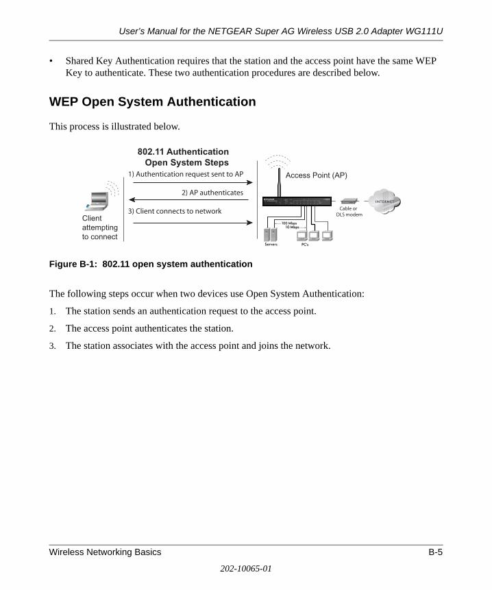
User’s Manual for the NETGEAR Super AG Wireless USB 2.0 Adapter WG111U
• Shared Key Authentication requires that the station and the access point have the same WEP Key to authenticate. These two authentication procedures are described below.
WEP Open System Authentication
This process is illustrated below.
Figure B-1: 802.11 open system authentication
The following steps occur when two devices use Open System Authentication:
1. The station sends an authentication request to the access point.
2. The access point authenticates the station.
3. The station associates with the access point and joins the network.
IN TER N ET LO CA L
ACT1 2 3 4 5 6 7 8
LNK
LNK/ACT
100Cable/DSL ProSafeWirelessVPN Security Firewall
MODEL FVM318
PWR TEST
W LA N
Enable
Access Point (AP)1) Authentication request sent to AP
2) AP authenticates
3) Client connects to network
802.11 AuthenticationOpen System Steps
Cable orDLS modem
Clientattemptingto connect
Wireless Networking Basics B-5
202-10065-01

User’s Manual for the NETGEAR Super AG Wireless USB 2.0 Adapter WG111U
WEP Shared Key Authentication
This process is illustrated below.
Figure B-2: 802.11 shared key authentication
The following steps occur when two devices use Shared Key Authentication:
1. The station sends an authentication request to the access point.
2. The access point sends challenge text to the station.
3. The station uses its configured 64-bit or 128-bit default key to encrypt the challenge text, and sends the encrypted text to the access point.
4. The access point decrypts the encrypted text using its configured WEP key that corresponds to the station’s default key. The access point compares the decrypted text with the original challenge text. If the decrypted text matches the original challenge text, then the access point and the station share the same WEP key and the access point authenticates the station.
5. The station connects to the network.
If the decrypted text does not match the original challenge text (i.e., the access point and station do not share the same WEP key), then the access point will refuse to authenticate the station and the station will be unable to communicate with either the 802.11 network or Ethernet network.
IN TER N ET LO CA L
ACT1 2 3 4 5 6 7 8
LNK
LNK/ACT
100Cable/DSL ProSafeWirelessVPN Security Firewall
MODEL FVM318
PWR TEST
W LA N
Enable
Access Point (AP)1) Authenticationrequest sent to AP
2) AP sends challenge text
3) Client encryptschallenge text andsends it back to AP
4) AP decrypts, and if correct,authenticates client
5) Client connects to network
802.11 AuthenticationShared Key Steps
Cable orDLS modem
Clientattemptingto connect
B-6 Wireless Networking Basics
202-10065-01

User’s Manual for the NETGEAR Super AG Wireless USB 2.0 Adapter WG111U
Key Size and Configuration
The IEEE 802.11 standard supports two types of WEP encryption: 40-bit and 128-bit.
The 64-bit WEP data encryption method, allows for a five-character (40-bit) input. Additionally, 24 factory-set bits are added to the forty-bit input to generate a 64-bit encryption key. (The 24 factory-set bits are not user-configurable). This encryption key will be used to encrypt/decrypt all data transmitted via the wireless interface. Some vendors refer to the 64-bit WEP data encryption as 40-bit WEP data encryption since the user-configurable portion of the encryption key is 40 bits wide.
The 128-bit WEP data encryption method consists of 104 user-configurable bits. Similar to the 40-bit WEP data encryption method, the remaining 24 bits are factory set and not user configurable. Some vendors allow passphrases to be entered instead of the cryptic hexadecimal characters to ease encryption key entry.
The 128-bit encryption is stronger than 40-bit encryption, but 128-bit encryption may not be available outside of the United States due to U.S. export regulations.
When configured for 40-bit encryption, 802.11 products typically support up to four WEP keys. Each 40-bit WEP Key is expressed as five sets of two hexadecimal digits (0-9 and A-F). For example, “12 34 56 78 90” is a 40-bit WEP key.
When configured for 128-bit encryption, 802.11g products typically support four WEP keys but some manufacturers support only one 128-bit key. The 128-bit WEP Key is expressed as 13 sets of two hexadecimal digits (0-9 and A-F). For example, “12 34 56 78 90 AB CD EF 12 34 56 78 90” is a 128-bit WEP key.
Typically, 802.11 access points can store up to four 128-bit WEP Keys but some 802.11 client adapters can only store one. Therefore, make sure that your 802.11 access and client adapters configurations match.
Whatever keys you enter for an access point, you must also enter the same keys for the client adapter in the same order. In other words, WEP key 1 on the AP must match WEP key 1 on the client adapter, WEP key 2 on the AP must match WEP key 2 on the client adapter, etc.
Note: The access point and the client adapters can have different default WEP keys as long as the keys are in the same order. In other words, the AP can use WEP key 2 as its default key to transmit while a client adapter can use WEP key 3 as its default key to transmit. The two devices will communicate as long as the access point’s WEP key 2 is the same as the client’s WEP key 2 and the AP’s WEP key 3 is the same as the client’s WEP key 3.
Wireless Networking Basics B-7
202-10065-01

User’s Manual for the NETGEAR Super AG Wireless USB 2.0 Adapter WG111U
How to Use WEP Parameters
Wired Equivalent Privacy (WEP) data encryption is used when the wireless devices are configured to operate in Shared Key authentication mode. There are two shared key methods implemented in most commercially available products, 64-bit and 128-bit WEP data encryption.
Before enabling WEP on an 802.11 network, you must first consider what type of encryption you require and the key size you want to use. Typically, there are three WEP Encryption options available for 802.11 products:
1. Do Not Use WEP: The 802.11 network does not encrypt data. For authentication purposes, the network uses Open System Authentication.
2. Use WEP for Encryption: A transmitting 802.11 device encrypts the data portion of every packet it sends using a configured WEP Key. The receiving 802.11g device decrypts the data using the same WEP Key. For authentication purposes, the 802.11g network uses Open System Authentication.
3. Use WEP for Authentication and Encryption: A transmitting 802.11 device encrypts the data portion of every packet it sends using a configured WEP Key. The receiving 802.11 device decrypts the data using the same WEP Key. For authentication purposes, the 802.11 network uses Shared Key Authentication.
Note: Some 802.11 access points also support Use WEP for Authentication Only (Shared Key Authentication without data encryption). However, the WG111U does not offer this option.
WPA Wireless Security
Wi-Fi Protected Access (WPA) is a specification of standards-based, interoperable security enhancements that increase the level of data protection and access control for existing and future wireless LAN systems.
The IEEE introduced the WEP as an optional security measure to secure 802.11g (Wi-Fi) WLANs, but inherent weaknesses in the standard soon became obvious. In response to this situation, the Wi-Fi Alliance announced a new security architecture in October 2002 that remedies the short comings of WEP. This standard, formerly known as Safe Secure Network (SSN), is designed to work with existing 802.11 products and offers forward compatibility with 802.11i, the new wireless security architecture being defined in the IEEE.
WPA offers the following benefits:
B-8 Wireless Networking Basics
202-10065-01

User’s Manual for the NETGEAR Super AG Wireless USB 2.0 Adapter WG111U
• Enhanced data privacy• Robust key management• Data origin authentication• Data integrity protection
Starting in August of 2003, all new Wi-Fi certified products had to support WPA and all existing Wi-Fi certified products had one year to comply with the new standard or lose their Wi-Fi certification. NETGEAR has implemented WPA on client and access point products. As of August 2004, all Wi-Fi certified products must support WPA.
How Does WPA Compare to WEP?
WEP is a data encryption method and is not intended as a user authentication mechanism. WPA user authentication is implemented using 802.1x and the Extensible Authentication Protocol (EAP). Support for 802.1x authentication is required in WPA. In the 802.11 standard, 802.1x authentication was optional. For details on EAP specifically, refer to IETF's RFC 2284.
With 802.11 WEP, all access points and client wireless adapters on a particular wireless LAN must use the same encryption key. A major problem with the 802.11 standard is that the keys are cumbersome to change. If you don't update the WEP keys often, an unauthorized person with a sniffing tool can monitor your network for less than a day and decode the encrypted messages. Products based on the 802.11 standard alone offer system administrators no effective method to update the keys.
For 802.11, WEP encryption is optional. For WPA, encryption using Temporal Key Integrity Protocol (TKIP) is required. TKIP replaces WEP with a new encryption algorithm that is stronger than the WEP algorithm, but that uses the calculation facilities present on existing wireless devices to perform encryption operations. TKIP provides important data encryption enhancements including a per-packet key mixing function, a message integrity check (MIC) named Michael, an extended initialization vector (IV) with sequencing rules, and a re-keying mechanism. Through these enhancements, TKIP addresses all of known WEP vulnerabilities.
Wireless Networking Basics B-9
202-10065-01

User’s Manual for the NETGEAR Super AG Wireless USB 2.0 Adapter WG111U
How Does WPA Compare to IEEE 802.11i?
WPA is forward compatible with the IEEE 802.11i security specification currently under development. WPA is a subset of the current 802.11i draft and uses certain pieces of the 802.11i draft that were ready to bring to market in 2003, such as 802.1x and TKIP. The main pieces of the 802.11i draft that are not included in WPA are secure IBSS (Ad-Hoc mode), secure fast handoff (for specialized 802.11 VoIP phones), as well as enhanced encryption protocols such as AES-CCMP. These features are either not yet ready for market or will require hardware upgrades to implement.
What are the Key Features of WPA Security?
The following security features are included in the WPA standard:
• WPA Authentication• WPA Encryption Key Management
– Temporal Key Integrity Protocol (TKIP)
– Michael message integrity code (MIC)
– AES Support
• Support for a Mixture of WPA and WEP Wireless Clients
These features are discussed below.
WPA addresses most of the known WEP vulnerabilities and is primarily intended for wireless infrastructure networks as found in the enterprise. This infrastructure includes stations, access points, and authentication servers (typically RADIUS servers). The RADIUS server holds (or has access to) user credentials (e.g., user names and passwords) and authenticates wireless users before they gain access to the network.
The strength WPA comes from an integrated sequence of operations that encompass 802.1X/EAP authentication and sophisticated key management and encryption techniques. Its major operations include:
• Network security capability determination. This occurs at the 802.11 level and is communicated through WPA information elements in Beacon, Probe Response, and (Re) Association Requests. Information in these elements includes the authentication method (802.1X or Pre-shared key) and the preferred cipher suite (WEP, TKIP, or AES).
B-10 Wireless Networking Basics
202-10065-01
User’s Manual for the NETGEAR Super AG Wireless USB 2.0 Adapter WG111U
The primary information conveyed in the Beacon frames is the authentication method and the cipher suite. Possible authentication methods include 802.1X and Pre-shared key. Pre-shared key is an authentication method that uses a statically configured passphrase on both the stations and the access point. This removes the need for an authentication server, which in many home and small office environments will not be available nor desirable. Possible cipher suites include: WEP, TKIP, and AES (Advanced Encryption Standard). We’ll talk more TKIP and AES when addressing data privacy below.
• Authentication. EAP over 802.1X is used for authentication. Mutual authentication is gained by choosing an EAP type supporting this feature and is required by WPA. The 802.1X port access control prevents full access to the network until authentication completes. The 802.1X EAPOL-Key packets are used by WPA to distribute per-session keys to those stations successfully authenticated.
The supplicant in the station uses the authentication and cipher suite information contained in the information elements to decide which authentication method and cipher suite to use. For example, if the access point is using the Pre-shared key method then the supplicant need not authenticate using full-blown 802.1X. Rather, the supplicant must simply prove to the access point that it is in possession of the pre-shared key. If the supplicant detects that the service set does not contain a WPA information element then it knows it must use pre-WPA 802.1X authentication and key management in order to access the network.
• Key management. WPA features a robust key generation/management system that integrates the authentication and data privacy functions. Keys are generated after successful authentication and through a subsequent four-way handshake between the station and access point (AP).
• Data Privacy (Encryption). Temporal Key Integrity Protocol (TKIP) is used to wrap WEP in sophisticated cryptographic and security techniques to overcome most of its weaknesses.
• Data integrity. TKIP includes a message integrity code (MIC) at the end of each plain text message to ensure messages are not being spoofed.
Wireless Networking Basics B-11
202-10065-01
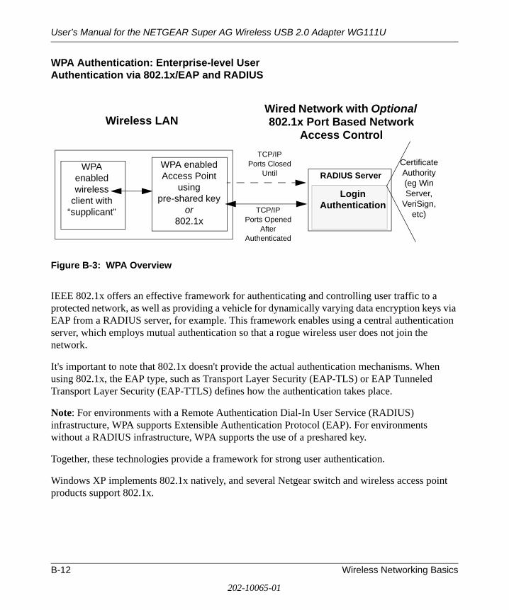
User’s Manual for the NETGEAR Super AG Wireless USB 2.0 Adapter WG111U
WPA Authentication: Enterprise-level User Authentication via 802.1x/EAP and RADIUS
Figure B-3: WPA Overview
IEEE 802.1x offers an effective framework for authenticating and controlling user traffic to a protected network, as well as providing a vehicle for dynamically varying data encryption keys via EAP from a RADIUS server, for example. This framework enables using a central authentication server, which employs mutual authentication so that a rogue wireless user does not join the network.
It's important to note that 802.1x doesn't provide the actual authentication mechanisms. When using 802.1x, the EAP type, such as Transport Layer Security (EAP-TLS) or EAP Tunneled Transport Layer Security (EAP-TTLS) defines how the authentication takes place.
Note: For environments with a Remote Authentication Dial-In User Service (RADIUS) infrastructure, WPA supports Extensible Authentication Protocol (EAP). For environments without a RADIUS infrastructure, WPA supports the use of a preshared key.
Together, these technologies provide a framework for strong user authentication.
Windows XP implements 802.1x natively, and several Netgear switch and wireless access point products support 802.1x.
WPA enabled wireless
client with “supplicant”
Certificate Authority (eg Win Server,
VeriSign, etc)
TCP/IPPorts Closed
Until RADIUS Server
Wired Network with Optional 802.1x Port Based Network
Access Control
WPA enabledAccess Point
usingpre-shared key
or 802.1x
TCP/IPPorts Opened
After Authenticated
Wireless LAN
LoginAuthentication
B-12 Wireless Networking Basics
202-10065-01

User’s Manual for the NETGEAR Super AG Wireless USB 2.0 Adapter WG111U
Figure B-4: 802.1x Authentication Sequence
The access point (AP) sends Beacon Frames with WPA information elements to the stations in the service set. Information elements include the required authentication method (802.1x or Pre-shared key) and the preferred cipher suite (WEP, TKIP, or AES). Probe Responses (AP to station) and Association Requests (station to AP) also contain WPA information elements.
1. Initial 802.1x communications begin with an unauthenticated supplicant (i.e., client device) attempting to connect with an authenticator (i.e., 802.11 access point). The client sends an EAP-start message. This begins a series of message exchanges to authenticate the client.
2. The access point replies with an EAP-request identity message.
12
3
4
56
7
Client with a WPA- enabled wireless adapter and supplicant (Win XP, Funk, Meetinghouse, etc.)
For example, a WPA-enabled AP
For example, a RADIUS server
Wireless Networking Basics B-13
202-10065-01

User’s Manual for the NETGEAR Super AG Wireless USB 2.0 Adapter WG111U
3. The client sends an EAP-response packet containing the identity to the authentication server. The access point responds by enabling a port for passing only EAP packets from the client to an authentication server located on the wired side of the access point. The access point blocks all other traffic, such as HTTP, DHCP, and POP3 packets, until the access point can verify the client's identity using an authentication server (e.g., RADIUS).
4. The authentication server uses a specific authentication algorithm to verify the client's identity. This could be through the use of digital certificates or some other EAP authentication type.
5. The authentication server will either send an accept or reject message to the access point.
6. The access point sends an EAP-success packet (or reject packet) to the client.
7. If the authentication server accepts the client, then the access point will transition the client's port to an authorized state and forward additional traffic.
The important part to know at this point is that the software supporting the specific EAP type resides on the authentication server and within the operating system or application “supplicant” software on the client devices. The access point acts as a “pass through” for 802.1x messages, which means that you can specify any EAP type without needing to upgrade an 802.1x-compliant access point. As a result, you can update the EAP authentication type to such devices as token cards (Smart Cards), Kerberos, one-time passwords, certificates, and public key authentication or as newer types become available and your requirements for security change.
WPA Data Encryption Key Management
With 802.1x, the rekeying of unicast encryption keys is optional. Additionally, 802.11 and 802.1x provide no mechanism to change the global encryption key used for multicast and broadcast traffic. With WPA, rekeying of both unicast and global encryption keys is required.
For the unicast encryption key, the Temporal Key Integrity Protocol (TKIP) changes the key for every frame, and the change is synchronized between the wireless client and the wireless access point (AP). For the global encryption key, WPA includes a facility (the Information Element) for the wireless AP to advertise the changed key to the connected wireless clients.
If configured to implement dynamic key exchange, the 802.1x authentication server can return session keys to the access point along with the accept message. The access point uses the session keys to build, sign and encrypt an EAP key message that is sent to the client immediately after sending the success message. The client can then use contents of the key message to define applicable encryption keys. In typical 802.1x implementations, the client can automatically change encryption keys as often as necessary to minimize the possibility of eavesdroppers having enough time to crack the key in current use.
B-14 Wireless Networking Basics
202-10065-01
User’s Manual for the NETGEAR Super AG Wireless USB 2.0 Adapter WG111U
Temporal Key Integrity Protocol (TKIP)
WPA uses TKIP to provide important data encryption enhancements including a per-packet key mixing function, a message integrity check (MIC) named Michael, an extended initialization vector (IV) with sequencing rules, and a re-keying mechanism. TKIP also provides for the following:
• The verification of the security configuration after the encryption keys are determined. • The synchronized changing of the unicast encryption key for each frame. • The determination of a unique starting unicast encryption key for each preshared key
authentication.
Michael
With 802.11 and WEP, data integrity is provided by a 32-bit integrity check value (ICV) that is appended to the 802.11 payload and encrypted with WEP. Although the ICV is encrypted, you can use cryptanalysis to change bits in the encrypted payload and update the encrypted ICV without being detected by the receiver.
With WPA, a method known as Michael specifies a new algorithm that calculates an 8-byte message integrity code (MIC) using the calculation facilities available on existing wireless devices. The MIC is placed between the data portion of the IEEE 802.11 frame and the 4-byte ICV. The MIC field is encrypted together with the frame data and the ICV.
Michael also provides replay protection. A new frame counter in the IEEE 802.11 frame is used to prevent replay attacks.
AES Support
One of the encryption methods supported by WPA beside TKIP is the advanced encryption standard (AES), although AES support will not be required initially for Wi-Fi certification. This is viewed as the optimal choice for security conscience organizations, but the problem with AES is that it requires a fundamental redesign of the NIC’s hardware in both the station and the access point. TKIP was a pragmatic compromise that allows organizations to deploy better security while AES capable equipment is being designed, manufactured, and incrementally deployed.
Wireless Networking Basics B-15
202-10065-01

User’s Manual for the NETGEAR Super AG Wireless USB 2.0 Adapter WG111U
Is WPA Perfect?
WPA is not without its vulnerabilities. Specifically, it is susceptible to denial of service (DoS) attacks. If the access point receives two data packets that fail the Message Integrity Code (MIC) check within 60 seconds of each other then the network is under an active attack, and as a result, the access point employs counter measures, which includes disassociating each station using the access point. This prevents an attacker from gleaning information about the encryption key and alerts administrators, but it also causes users to lose network connectivity for 60 seconds. More than anything else, this may just prove that no single security tactic is completely invulnerable. WPA is a definite step forward in WLAN security over WEP and has to be thought of as a single part of an end-to-end network security strategy.
Product Support for WPA
Starting in August, 2003, NETGEAR, Inc. wireless Wi-Fi certified products will support the WPA standard. NETGEAR, Inc. wireless products that had their Wi-Fi certification approved before August, 2003 will have one year to add WPA so as to maintain their Wi-Fi certification.
WPA requires software changes to the following:
• Wireless access points • Wireless network adapters • Wireless client programs
Supporting a Mixture of WPA and WEP Wireless Clients
To support the gradual transition of WEP-based wireless networks to WPA, a wireless AP can support both WEP and WPA clients at the same time. During the association, the wireless AP determines which clients use WEP and which clients use WPA. The disadvantage to supporting a mixture of WEP and WPA clients is that the global encryption key is not dynamic. This is because WEP-based clients cannot support it. All other benefits to the WPA clients, such as integrity, are maintained.
However, a mixed mode supporting WPA and non-WPA clients would offer network security that is no better than that obtained with a non-WPA network, and thus this mode of operation is discouraged.
Changes to Wireless Access Points
Wireless access points must have their firmware updated to support the following:
B-16 Wireless Networking Basics
202-10065-01
User’s Manual for the NETGEAR Super AG Wireless USB 2.0 Adapter WG111U
• The new WPA information element To advertise their support of WPA, wireless APs send the beacon frame with a new 802.11 WPA information element that contains the wireless AP's security configuration (encryption algorithms and wireless security configuration information).
• The WPA two-phase authentication Open system, then 802.1x (EAP with RADIUS or preshared key).
• TKIP • Michael • AES (optional)
To upgrade your wireless access points to support WPA, obtain a WPA firmware update from your wireless AP vendor and upload it to your wireless AP.
Changes to Wireless Network Adapters
Wireless network adapters must have their firmware updated to support the following:
• The new WPA information element Wireless clients must be able to process the WPA information element and respond with a specific security configuration.
• The WPA two-phase authentication Open system, then 802.1x (EAP or preshared key).
• TKIP • Michael • AES (optional)
To upgrade your wireless network adapters to support WPA, obtain a WPA update from your wireless network adapter vendor and update the wireless network adapter driver.
For Windows wireless clients, you must obtain an updated network adapter driver that supports WPA. For wireless network adapter drivers that are compatible with Windows XP (Service Pack 1) and Windows Server 2003, the updated network adapter driver must be able to pass the adapter's WPA capabilities and security configuration to the Wireless Zero Configuration service.
Microsoft has worked with many wireless vendors to embed the WPA firmware update in the wireless adapter driver. So, to update you Windows wireless client, all you have to do is obtain the new WPA-compatible driver and install the driver. The firmware is automatically updated when the wireless network adapter driver is loaded in Windows.
Wireless Networking Basics B-17
202-10065-01

User’s Manual for the NETGEAR Super AG Wireless USB 2.0 Adapter WG111U
Changes to Wireless Client Programs
Wireless client programs must be updated to permit the configuration of WPA authentication (and preshared key) and the new WPA encryption algorithms (TKIP and the optional AES component).
To obtain the Microsoft WPA client program, visit the Microsoft Web site.
B-18 Wireless Networking Basics
202-10065-01

Appendix CPreparing Your Network to Work with a Router
This appendix describes how to prepare your network to connect to the Internet through a router and how to verify the readiness of your broadband Internet service from an Internet service provider (ISP).
What You Need To Use a Router with a Broadband Modem
You need to prepare these three things before you begin:
Cabling and Computer HardwareTo use the router on your network, each computer must have an 802.11g or 802.11b wireless adapter or an installed Ethernet Network Interface Card (NIC) and an Ethernet cable. If the computer will connect to your network using an Ethernet NIC at 100 Mbps, you must use a Category 5 (Cat 5) cable such as the one provided with your router. The cable or DSL broadband modem must provide a standard 10 Mbps (10BASE-T) or 100 Mbps (100BASE-Tx) Ethernet interface.
Computer Network Configuration RequirementsThe router includes a built-in Web Configuration Manager. To access the configuration menus on the router, your must use a Java-enabled Web browser program that supports HTTP uploads such as Microsoft Internet Explorer or Netscape Navigator. Use Internet Explorer or Netscape Navigator 4.0 or above.
Note: If your computer was configured during the installation of a broadband modem, or using instructions provided by your ISP, you may need to copy the ISP configuration information for use in the configuration of your router. Write down this information before reconfiguring your computers. Refer to “Obtaining ISP Configuration Information for Windows Computers” on page Appendix C-19 or “Obtaining ISP Configuration Information for Macintosh Computers” on page Appendix C-20 for further information.
Preparing Your Network to Work with a Router Appendix C-1
202-10065-01
User’s Manual for the NETGEAR Super AG Wireless USB 2.0 Adapter WG111U
For the initial setup of your router, you will need to connect a computer to the router. This computer has to be set to automatically get its TCP/IP configuration from the router via DHCP.
Note: For help with DHCP configuration, please use the Windows TCP/IP Configuration Tutorials on the Resource CD.
Internet Configuration RequirementsDepending on how your Internet service set up your account, you may need one or more of these configuration parameters to connect your router to the Internet:
• Host and Domain Names• ISP Login Name and Password• ISP Domain Name Server (DNS) Addresses• Fixed IP Address, which is also known as the Static IP Address
Where Do I Get the Internet Configuration Parameters?There are several ways you can gather the required Internet connection information:
• Your Internet service provides all the information needed to connect to the Internet. If you cannot locate this information, you can ask your Internet service provider to provide it or you can try one of the options below.
• If you have a computer already connected to the Internet, you can gather the configuration information from that computer.
— For Windows 95/98/ME, open the Network control panel, select the TCP/IP entry for the Ethernet adapter, and click Properties. Record all the settings for each tab page.
— For Windows 2000/XP, open the Local Area Network Connection, select the TCP/IP entry for the Ethernet adapter, and click Properties. Record all the settings for each tab page.
— For Macintosh computers, record the settings in the TCP/IP or Network control panel.
• You may also refer to the Resource CD or the NETGEAR Router ISP Guide, which provides Internet connection information for many ISPs.
Once you locate your Internet configuration parameters, you may want to record them on the page below.
Appendix C-2 Preparing Your Network to Work with a Router
202-10065-01

User’s Manual for the NETGEAR Super AG Wireless USB 2.0 Adapter WG111U
Record Your Internet Connection InformationPrint this page. Fill in the configuration parameters from your Internet Service Provider (ISP).
ISP Login Name: The login name and password are case sensitive and must be entered exactly as given by your ISP. Some ISPs use your full e-mail address as the login name. The Service Name is not required by all ISPs. If you connect using a login name and password, enter the following:
Login Name: ______________________________
Password: ____________________________
Service Name: _____________________________
Fixed or Static IP Address: If you have a static IP address, record the following information. For example, 169.254.141.148 could be a valid IP address.
Fixed or Static Internet IP Address: ______ ______ ______ ______
Gateway IP Address: ______ ______ ______ ______
Subnet Mask: ______ ______ ______ ______
ISP DNS Server Addresses: If you were given DNS server addresses, fill in the following:
Primary DNS Server IP Address: ______ ______ ______ ______
Secondary DNS Server IP Address: ______ ______ ______ ______
Host and Domain Names: Some ISPs use a specific host or domain name like CCA7324-A or home. If you have not been given host or domain names, you can use the following examples as a guide:
• If your main e-mail account with your ISP is [email protected], then use aaa as your host name. Your ISP might call this your account, user, host, or system name.
• If your ISP’s mail server is mail.xxx.yyy.com, then use xxx.yyy.com as the domain name.
ISP Host Name: _________________________ ISP Domain Name: _______________________
For Wireless Access: See the configuration worksheet in the Resource Manual for your NETGEAR wireless equipment.
Preparing Your Network to Work with a Router Appendix C-3
202-10065-01

User’s Manual for the NETGEAR Super AG Wireless USB 2.0 Adapter WG111U
Preparing Your Computers for TCP/IP Networking
Computers access the Internet using a protocol called TCP/IP (Transmission Control Protocol/Internet Protocol). Each computer on your network must have TCP/IP installed and selected as its networking protocol. If a Network Interface Card (NIC) is already installed in your computer, then TCP/IP is probably already installed as well.
Most operating systems include the software components you need for networking with TCP/IP:
• Windows® 95 or later includes the software components for establishing a TCP/IP network.
• Windows 3.1 does not include a TCP/IP component. You need to purchase a third-party TCP/IP application package such as NetManage Chameleon.
• Macintosh Operating System 7 or later includes the software components for establishing a TCP/IP network.
• All versions of UNIX or Linux include TCP/IP components. Follow the instructions provided with your operating system or networking software to install TCP/IP on your computer.
In your IP network, each computer and the router must be assigned unique IP addresses. Each computer must also have certain other IP configuration information such as a subnet mask (netmask), a domain name server (DNS) address, and a default gateway address. In most cases, you should install TCP/IP so that the computer obtains its specific network configuration information automatically from a DHCP server during bootup.
The router is shipped preconfigured as a DHCP server. The router assigns the following TCP/IP configuration information automatically when the computers are rebooted.
These addresses are part of the IETF-designated private address range for use in private networks.
TCP/IP Configuration Current NETGEAR Standard Previous NETGEAR Standard
Computer or workstation IP Address
192.168.1.2 through 192.168.1.254
192.168.0.2 through 192.168.0.254
Subnet mask 255.255.255.0 255.255.255.0
Gateway address for router 192.168.1.1 default address 192.168.0.1 default address
Appendix C-4 Preparing Your Network to Work with a Router
202-10065-01

User’s Manual for the NETGEAR Super AG Wireless USB 2.0 Adapter WG111U
Configuring Windows 95, 98, and Me for TCP/IP Networking
As part of the computer preparation process, you need to manually install and configure TCP/IP on each networked computer. Before starting, locate your Windows CD; you may need to insert it during the TCP/IP installation process.
Installing or Verifying Windows Networking ComponentsTo install or verify the necessary components for IP networking:
1. On the Windows taskbar, click the Start button, point to Settings, and then click Control Panel.
2. Double-click the Network icon.
The Network window opens and displays a list of installed components.
3. Make sure that the following components are installed:
• Client for Microsoft Networks• Ethernet Adapter• TCP/IP
4. The Primary Network Logon should be set to Client for Microsoft Networks.
5. If any of these items needs to be installed, follow the steps below.
Note: It is not necessary to remove any other network components shown in the Network window in order to install the adapter, TCP/IP, or the Client for Microsoft Networks.
Installing a New AdapterIf you need to install a new adapter, follow these steps:
a. Click the Add button.
b. Select Adapter, and then click Add.
c. Select the manufacturer and model of your Ethernet adapter, and then click OK.
Preparing Your Network to Work with a Router Appendix C-5
202-10065-01

User’s Manual for the NETGEAR Super AG Wireless USB 2.0 Adapter WG111U
Installing TCP/IPIf you need TCP/IP:
a. Click the Add button.
b. Select Protocol, and then click Add.
c. Select Microsoft.
d. Select TCP/IP, and then click OK.
Installing the Client for Microsoft NetworksIf you need the Client for Microsoft Networks:
a. Click the Add button.
b. Select Client, and then click Add.
c. Select Microsoft.
d. Select Client for Microsoft Networks, and then click OK.
6. Restart your computer for the changes to take effect.
Enabling DHCP to Automatically Configure TCP/IP Settings in Windows 95B, 98, and Me After the TCP/IP protocol components are installed, each computer must be assigned specific information about itself and resources that are available on its network. The simplest way to configure this information is to allow the computer to obtain the information from a DHCP server in the network.
There are many similarities in the procedures for different Windows systems when using DHCP to configure TCP/IP. The following steps walk you through the configuration process for each of these versions of Windows.
Appendix C-6 Preparing Your Network to Work with a Router
202-10065-01

User’s Manual for the NETGEAR Super AG Wireless USB 2.0 Adapter WG111U
1. Open the Network Panel
• If the Network Neighborhood icon is on the Windows desktop, position your mouse pointer over it and right-click your mouse button.
• If the icon is not on the desktop:
— On the Windows taskbar, click the Start button, point to Settings, and then click Control Panel.
— Locate the Network Neighborhood icon and click on it.
The Network panel opens as shown to the right.
2. Verify the Configuration Settings
a. On the Configuration tab, make sure that the following components are installed:
• Client for Microsoft Networks• Ethernet Adapter• TCP/IP
b. The Primary Network Logon should be set to Windows Logon.
Preparing Your Network to Work with a Router Appendix C-7
202-10065-01

User’s Manual for the NETGEAR Super AG Wireless USB 2.0 Adapter WG111U
3. Verify the Properties IP Address Setting
a. Click the Properties button.
The TCP/IP Properties window displays as shown to the right. By default, the IP Address tab is open.
b. Verify that “Obtain an IP address automatically” is selected.
If it is not selected, click the radio button to the left of it to select it. This setting is required to enable the DHCP server to automatically assign an IP address.
c. Click OK to continue.
d. Restart the computer.
e. Repeat these steps for each computer with this version of Windows on your network.
Selecting the Windows’ Internet Access Method1. On the Windows taskbar, click the Start button, point to Settings, and then click Control Panel.
2. Double-click the Internet Options icon.
3. Select “I want to set up my Internet connection manually” or “I want to connect through a Local Area Network” and click Next.
4. Clear all the check boxes in the LAN Internet Configuration screen and click Next.
5. Proceed to the end of the Wizard.
Verifying TCP/IP PropertiesAfter your computer is configured and has rebooted, you can check the TCP/IP configuration using the utility winipcfg.exe:
1. On the Windows taskbar, click the Start button, and then click Run.
2. Type winipcfg, and then click OK.
The IP Configuration window opens and lists (among other things), your IP address, subnet mask, and default gateway.
Appendix C-8 Preparing Your Network to Work with a Router
202-10065-01

User’s Manual for the NETGEAR Super AG Wireless USB 2.0 Adapter WG111U
3. From the drop-down box, select your Ethernet adapter.
The window is updated to show your settings. They should match the values below if you are using the default TCP/IP settings that NETGEAR recommends for connecting through a router or gateway:
Configuring Windows NT4, 2000 or XP for IP Networking
As part of the computer preparation process, you may need to install and configure TCP/IP on each networked computer. Before starting, locate your Windows CD; you may need to insert it during the TCP/IP installation process.
Installing or Verifying Windows Networking ComponentsTo install or verify the necessary components for IP networking:
1. On the Windows taskbar, click the Start button, then click Control Panel.
2. Double-click the Network Connections icon.
3. If an Ethernet adapter is present in your computer, you should see an entry for Local Area Connection. Double-click that entry.
4. Select Properties.
5. Verify that Client for Microsoft Networks and Internet Protocol (TCP/IP) are present. If not, select Install and add them.
6. Select “Internet Protocol (TCP/IP)”, click Properties, and verify that “Obtain an IP address automatically” is selected.
7. Click OK and close all Network and Dialup Connections windows.
8. Then, restart your computer.
TCP/IP Configuration Current NETGEAR Standard Previous NETGEAR Standard
Computer or workstation IP Address
192.168.1.2 through 192.168.1.254
192.168.0.2 through 192.168.0.254
Subnet mask 255.255.255.0 255.255.255.0
Gateway address for router 192.168.1.1 default address 192.168.0.1 default address
Preparing Your Network to Work with a Router Appendix C-9
202-10065-01

User’s Manual for the NETGEAR Super AG Wireless USB 2.0 Adapter WG111U
Configuring DHCP of TCP/IP in Windows XP, 2000, or NT4There are many similarities in the procedures for different Windows systems when using DHCP to configure TCP/IP. The following steps walk you through the configuration process for each of these versions of Windows.
DHCP Configuration of TCP/IP in Windows XP 1. Open the Network Connection Window.
a. Select Control Panel from the Windows XP Start Menu.
b. Select the Network Connections icon on the Control Panel.
The Network Connection window displays as shown here. The Connections List is located to the right of that window.
2. Go to the Network Connection Status window.
Note: Administrator logon access rights are needed to use this window.
Double-click the Connection you will use.
The Local Area Network Connection Status window opens, as shown here. This box displays the connection status, duration, speed, and activity statistics.
Appendix C-10 Preparing Your Network to Work with a Router
202-10065-01

User’s Manual for the NETGEAR Super AG Wireless USB 2.0 Adapter WG111U
3. Go to Properties.
a. Click the Properties button to view details about the connection.
The TCP/IP details are shown on the Support tab page.
b. Select “Internet Protocol”, and click Properties to view the configuration information.
4. Set DHCP for TCP/IP.
a. Verify that the following two radio buttons are selected:
• Obtain an IP address automatically
• Obtain DNS server address automatically
b. Click the OK button.
This completes the DHCP configuration of TCP/IP in Windows XP for this computer.
c. Repeat these steps for each computer with this version of Windows on your network.
Preparing Your Network to Work with a Router Appendix C-11
202-10065-01
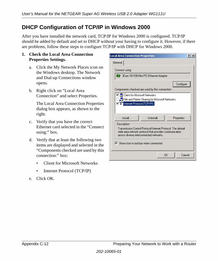
User’s Manual for the NETGEAR Super AG Wireless USB 2.0 Adapter WG111U
DHCP Configuration of TCP/IP in Windows 2000 After you have installed the network card, TCP/IP for Windows 2000 is configured. TCP/IP should be added by default and set to DHCP without your having to configure it. However, if there are problems, follow these steps to configure TCP/IP with DHCP for Windows 2000.
1. Check the Local Area Connection Properties Settings.
a. Click the My Network Places icon on the Windows desktop. The Network and Dial-up Connections window opens.
b. Right click on “Local Area Connection” and select Properties.
The Local Area Connection Properties dialog box appears, as shown to the right.
c. Verify that you have the correct Ethernet card selected in the “Connect using:” box.
d. Verify that at least the following two items are displayed and selected in the “Components checked are used by this connection:” box:
• Client for Microsoft Networks
• Internet Protocol (TCP/IP)
e. Click OK.
Appendix C-12 Preparing Your Network to Work with a Router
202-10065-01

User’s Manual for the NETGEAR Super AG Wireless USB 2.0 Adapter WG111U
2. Check the Internet Protocol Properties.
a. With “Internet Protocol (TCP/IP)” selected, click Properties to open the Internet Protocol (TCP/IP) Properties dialog box.
b. Verify that the following items are selected:
• Obtain an IP address automatically
• Obtain DNS server address automatically
c. Click OK to return to Local Area Connection Properties.
3. Complete the configuration.
a. Click OK again to complete the configuration process for Windows 2000.
b. Restart the computer.
c. Repeat these steps for each computer with this version of Windows on your network.
Preparing Your Network to Work with a Router Appendix C-13
202-10065-01

User’s Manual for the NETGEAR Super AG Wireless USB 2.0 Adapter WG111U
DHCP Configuration of TCP/IP in Windows NT4Once you have installed the network card, you need to configure the TCP/IP environment for Windows NT 4.0. Follow this procedure to configure TCP/IP with DHCP in Windows NT 4.0.
1. Open the Network panel.
a. Choose Settings from the Start Menu.
b. Select Control Panel to display Control Panel window.
c. Double-click the Network icon to display the Network panel, as shown to the right.
2. Go to TCP/IP Properties.
a. Select the Protocols tab.
b. Select “TCP/IP Protocol” in the Network Protocols box, and click the Properties button.
Appendix C-14 Preparing Your Network to Work with a Router
202-10065-01
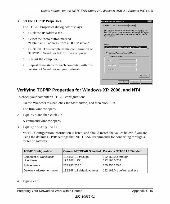
User’s Manual for the NETGEAR Super AG Wireless USB 2.0 Adapter WG111U
3. Set the TCP/IP Properties.
The TCP/IP Properties dialog box displays.
a. Click the IP Address tab.
b. Select the radio button marked “Obtain an IP address from a DHCP server”.
c. Click OK. This completes the configuration of TCP/IP in Windows NT for this computer.
d. Restart the computer.
e. Repeat these steps for each computer with this version of Windows on your network.
Verifying TCP/IP Properties for Windows XP, 2000, and NT4To check your computer’s TCP/IP configuration:
1. On the Windows taskbar, click the Start button, and then click Run.
The Run window opens.
2. Type cmd and then click OK.
A command window opens.
3. Type ipconfig /all
Your IP Configuration information is listed, and should match the values below if you are using the default TCP/IP settings that NETGEAR recommends for connecting through a router or gateway.
4. Type exit
TCP/IP Configuration Current NETGEAR Standard Previous NETGEAR Standard
Computer or workstation IP Address
192.168.1.2 through 192.168.1.254
192.168.0.2 through 192.168.0.254
Subnet mask 255.255.255.0 255.255.255.0
Gateway address for router 192.168.1.1 default address 192.168.0.1 default address
Preparing Your Network to Work with a Router Appendix C-15
202-10065-01
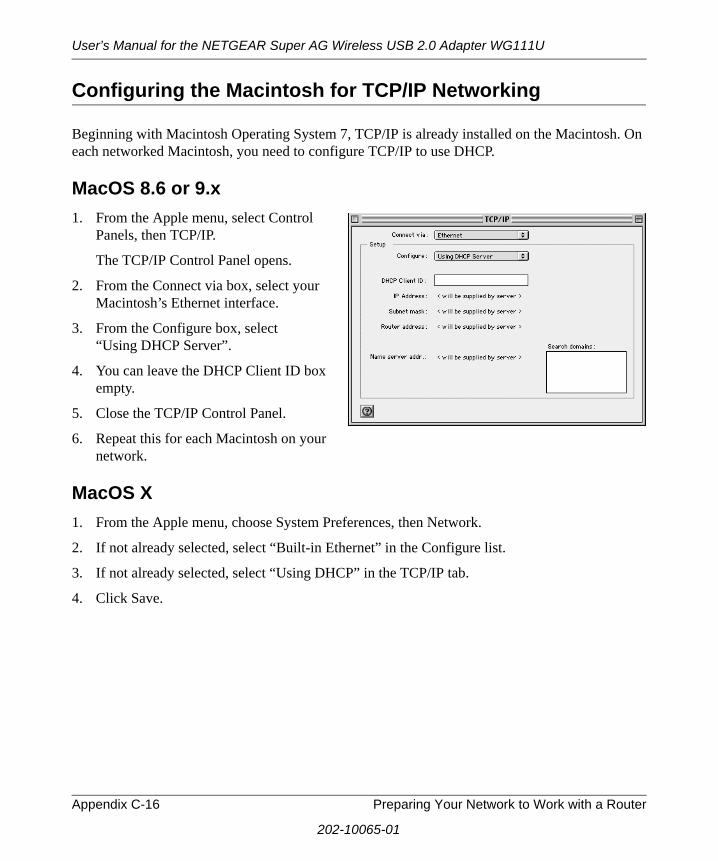
User’s Manual for the NETGEAR Super AG Wireless USB 2.0 Adapter WG111U
Configuring the Macintosh for TCP/IP Networking
Beginning with Macintosh Operating System 7, TCP/IP is already installed on the Macintosh. On each networked Macintosh, you need to configure TCP/IP to use DHCP.
MacOS 8.6 or 9.x1. From the Apple menu, select Control
Panels, then TCP/IP.
The TCP/IP Control Panel opens.
2. From the Connect via box, select your Macintosh’s Ethernet interface.
3. From the Configure box, select “Using DHCP Server”.
4. You can leave the DHCP Client ID box empty.
5. Close the TCP/IP Control Panel.
6. Repeat this for each Macintosh on your network.
MacOS X1. From the Apple menu, choose System Preferences, then Network.
2. If not already selected, select “Built-in Ethernet” in the Configure list.
3. If not already selected, select “Using DHCP” in the TCP/IP tab.
4. Click Save.
Appendix C-16 Preparing Your Network to Work with a Router
202-10065-01
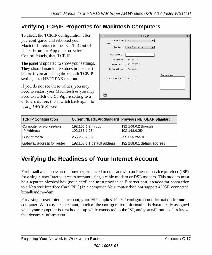
User’s Manual for the NETGEAR Super AG Wireless USB 2.0 Adapter WG111U
Verifying TCP/IP Properties for Macintosh ComputersTo check the TCP/IP configuration after you configured and rebooted your Macintosh, return to the TCP/IP Control Panel. From the Apple menu, select Control Panels, then TCP/IP.
The panel is updated to show your settings. They should match the values in the chart below if you are using the default TCP/IP settings that NETGEAR recommends.
If you do not see these values, you may need to restart your Macintosh or you may need to switch the Configure setting to a different option, then switch back again to Using DHCP Server.
Verifying the Readiness of Your Internet Account
For broadband access to the Internet, you need to contract with an Internet service provider (ISP) for a single-user Internet access account using a cable modem or DSL modem. This modem must be a separate physical box (not a card) and must provide an Ethernet port intended for connection to a Network Interface Card (NIC) in a computer. Your router does not support a USB-connected broadband modem.
For a single-user Internet account, your ISP supplies TCP/IP configuration information for one computer. With a typical account, much of the configuration information is dynamically assigned when your computer is first booted up while connected to the ISP, and you will not need to know that dynamic information.
TCP/IP Configuration Current NETGEAR Standard Previous NETGEAR Standard
Computer or workstation IP Address
192.168.1.2 through 192.168.1.254
192.168.0.2 through 192.168.0.254
Subnet mask 255.255.255.0 255.255.255.0
Gateway address for router 192.168.1.1 default address 192.168.0.1 default address
Preparing Your Network to Work with a Router Appendix C-17
202-10065-01

User’s Manual for the NETGEAR Super AG Wireless USB 2.0 Adapter WG111U
In order to share the Internet connection among several computers, your router takes the place of the single computer, and you need to configure it with the TCP/IP information that the single computer would normally use. When the router’s Internet port is connected to the broadband modem, the router appears to be a single computer to the ISP. The router then allows the computers on the local network to masquerade as the single computer to access the Internet through the broadband modem. The method used by the router to accomplish this is called Network Address Translation (NAT) or IP masquerading.
Are Login Protocols Used?Some ISPs require a special login protocol, in which you must enter a login name and password in order to access the Internet. If you normally log in to your Internet account by running a program such as WinPOET or EnterNet, then your account uses Point-to-Point Protocol over Ethernet (PPPoE).
When you configure your router, you need to enter your login name and password in the router’s configuration menus. After your network and router are configured, the router will perform the login task when needed, and you will no longer need to run the login program from your computer. It is not necessary to uninstall the login program.
What Is Your Configuration Information?More and more, ISPs are dynamically assigning configuration information. However, if your ISP does not dynamically assign configuration information but instead used fixed configurations, your ISP should have given you the following basic information for your account:
• An IP address and subnet mask
• A gateway IP address, which is the address of the ISP’s router
• One or more domain name server (DNS) IP addresses
• Host name and domain suffix
For example, your account’s full server names may look like this:
mail.xxx.yyy.com
In this example, the domain suffix is xxx.yyy.com.
If any of these items are dynamically supplied by the ISP, your router automatically acquires them.
Appendix C-18 Preparing Your Network to Work with a Router
202-10065-01

User’s Manual for the NETGEAR Super AG Wireless USB 2.0 Adapter WG111U
If an ISP technician configured your computer during the installation of the broadband modem, or if you configured it using instructions provided by your ISP, you need to copy the configuration information from your computer’s Network TCP/IP Properties window or Macintosh TCP/IP Control Panel before reconfiguring your computer for use with the router. These procedures are described next.
Obtaining ISP Configuration Information for Windows ComputersYou may need configuration information from your computer in order to configure the router. You only need to collect this information if you have a static IP address (your ISP does not dynamically supply the account information).
To get the information you need to configure the router for Internet access follow the steps below. The selections vary somewhat according to which version of Windows you are running.
1. On the Windows taskbar, click the Start button, point to Settings, and then click Control Panel.
2. Double-click the Network icon.
The Network window opens and displays a list of installed components.
3. Select TCP/IP, and then click Properties.
The TCP/IP Properties dialog box opens.
4. Select the IP Address tab.
If an IP address and subnet mask are shown, write down the information. If an address is present, your account uses a fixed (static) IP address. If no address is present, your account uses a dynamically-assigned IP address. Click Obtain an IP address automatically.
5. Select the Gateway tab.
If an IP address appears under Installed Gateways, write down the address. This is the ISP’s gateway address. Select the address and then click Remove to remove the gateway address.
6. Select the DNS Configuration tab.
If any DNS server addresses are shown, write down the addresses. If any information appears in the Host or Domain information box, write it down. Click Disable DNS.
7. Click OK to save your changes and close the TCP/IP Properties dialog box.
You are returned to the Network window.
8. Click OK.
9. Reboot your computer at the prompt. You may also be prompted to insert your Windows CD.
Preparing Your Network to Work with a Router Appendix C-19
202-10065-01
User’s Manual for the NETGEAR Super AG Wireless USB 2.0 Adapter WG111U
Obtaining ISP Configuration Information for Macintosh ComputersYou may need configuration information from your computer in order to configure the router. You only need to collect this information if you have a static IP address (your ISP does not dynamically supply the account information).
To get the information you need to configure the router for Internet access:
1. From the Apple menu, select Control Panels, then TCP/IP.
The TCP/IP Control Panel opens, and displays a list of configuration settings. If the “Configure” setting is Using DHCP Server, your account uses a dynamically-assigned IP address. In this case, close the Control Panel and skip the rest of this section.
2. If an IP address and subnet mask are shown, write down the information.
3. If an IP address appears under Router address, write down the address. This is the ISP’s gateway address.
4. If any Name Server addresses are shown, write down the addresses. These are your ISP’s DNS addresses.
5. If any information appears in the Search domains information box, write it down.
6. Change the Configure setting to Using DHCP Server.
7. Close the TCP/IP Control Panel.
Restarting the Network
Once you have set up your computers to work with the router, you must reset the network for the devices to be able to communicate correctly. Restart any computer that is connected to the router.
After you configure all of your computers for TCP/IP networking, restart them, and connect them to the local network of your router. Then you are ready to access and configure the router.
Appendix C-20 Preparing Your Network to Work with a Router
202-10065-01

Glossary
Use the list below to find definitions for technical terms used in this manual.
10BASE-T IEEE 802.3 specification for 10 Mbps Ethernet over twisted pair wiring.
100BASE-Tx IEEE 802.3 specification for 100 Mbps Ethernet over twisted pair wiring.
802.11bIEEE specification for wireless networking at 11 Mbps using direct-sequence spread-spectrum (DSSS) technology and operating in the unlicensed radio spectrum at 2.5GHz.
802.11gAn IEEE specification for wireless networking at 54 Mbps using direct-sequence spread-spectrum (DSSS) technology and operating in the unlicensed radio spectrum at 2.5GHz. 802.11g is backwards compatible with 802.11b.
ADSLShort for asymmetric digital subscriber line, a technology that allows data to be sent over existing copper telephone lines at data rates of from 1.5 to 9 Mbps when receiving data (known as the downstream rate) and from 16 to 640 Kbps when sending data (known as the upstream rate). ADSL requires a special ADSL modem. ADSL is growing in popularity as more areas around the world gain access.
DHCPAn Ethernet protocol specifying how a centralized DHCP server can assign network configuration information to multiple DHCP clients. The assigned information includes IP addresses, DNS addresses, and gateway (router) addresses.
DNSShort for Domain Name System (or Service), an Internet service that translates domain names into IP addresses. Because domain names are alphabetic, they're easier to remember. The Internet however, is really based on IP addresses. Every time you use a domain name, therefore, a DNS service must translate the name into the corresponding IP address. For example, the domain name www.example.com might translate to 198.105.232.4. The DNS system is, in fact, its own network. If one DNS server doesn't know how to translate a particular domain name, it asks another one, and so on, until the correct IP address is returned.
Glossary Glossary-1
202-10065-01

User’s Manual for the NETGEAR Super AG Wireless USB 2.0 Adapter WG111U
Domain NameA descriptive name for an address or group of addresses on the Internet. Domain names are of the form of a registered entity name plus one of a number of predefined top level suffixes such as .com, .edu, .uk, etc. For example, in the address mail.NETGEAR.com, mail is a server name and NETGEAR.com is the domain.
DSLShort for digital subscriber line, but is commonly used in reference to the asymmetric version of this technology (ADSL) that allows data to be sent over existing copper telephone lines at data rates of from 1.5 to 9 Mbps when receiving data (known as the downstream rate) and from 16 to 640 Kbps when sending data (known as the upstream rate). ADSL requires a special ADSL modem. ADSL is growing in popularity as more areas around the world gain access.
Dynamic Host Configuration ProtocolDHCP. An Ethernet protocol specifying how a centralized DHCP server can assign network configuration information to multiple DHCP clients. The assigned information includes IP addresses, DNS addresses, and gateway (router) addresses.
ESSIDThe Extended Service Set Identification (ESSID) is a thirty-two character (maximum) alphanumeric key identifying the wireless local area network.
GatewayA local device, usually a router, that connects hosts on a local network to other networks.
IETFInternet Engineering Task Force. Working groups of the IETF propose standard protocols and procedures for the Internet, which are published as RFCs (Request for Comment) at www.ietf.org.An open international community of network designers, operators, vendors, and researchers concerned with the evolution of the Internet architecture and the smooth operation of the Internet.
IPInternet Protocol is the main internetworking protocol used in the Internet. Used in conjunction with the Transfer Control Protocol (TCP) to form TCP/IP.
IP AddressA four-byte number uniquely defining each host on the Internet, usually written in dotted-decimal notation with periods separating the bytes (for example, 134.177.244.57). Ranges of addresses are assigned by Internic, an organization formed for this purpose.
IPXShort for Internetwork Packet Exchange, a networking protocol used by the Novell NetWare operating systems.
Glossary-2 Glossary
202-10065-01
User’s Manual for the NETGEAR Super AG Wireless USB 2.0 Adapter WG111U
Like UDP/IP, IPX is a datagram protocol used for connectionless communications. Higher-level protocols, such as SPX and NCP, are used for additional error recovery services.
ISPInternet service provider.
Internet ProtocolThe main internetworking protocol used in the Internet. Used in conjunction with the Transfer Control Protocol (TCP) to form TCP/IP.
LANA communications network serving users within a limited area, such as one floor of a building.
local area networkLAN. A communications network serving users within a limited area, such as one floor of a building. A LAN typically connects multiple personal computers and shared network devices such as storage and printers. Although many technologies exist to implement a LAN, Ethernet is the most common for connecting personal computers.
MAC addressThe Media Access Control address is a unique 48-bit hardware address assigned to every network interface card. Usually written in the form 01:23:45:67:89:ab.
MbpsMegabits per second.
NetBIOSThe Network Basic Input Output System is an application programming interface (API) for sharing services and information on local-area networks (LANs). Provides for communication between stations of a network where each station is given a name. These names are alphanumeric names, up to 16 characters in length.
Network Address TranslationNAT. A technique by which several hosts share a single IP address for access to the Internet.
NICNetwork Interface Card. An adapter in a computer which provides connectivity to a network.
packetA block of information sent over a network. A packet typically contains a source and destination network address, some protocol and length information, a block of data, and a checksum.
Glossary Glossary-3
202-10065-01

User’s Manual for the NETGEAR Super AG Wireless USB 2.0 Adapter WG111U
routerA device that forwards data between networks. An IP router forwards data based on IP source and destination addresses.
Routing Information ProtocolRIP. A protocol in which routers periodically exchange information with one another so that they can determine minimum distance paths between sources and destinations.
SSIDA Service Set Identification is a thirty-two character (maximum) alphanumeric key identifying a wireless local area network. For the wireless devices in a network to communicate with each other, all devices must be configured with the same SSID. This is typically the configuration parameter for a wireless adapter. It corresponds to the ESSID in the wireless Access Point and to the wireless network name. See also Wireless Network Name and ESSID.
Subnet MaskA mask used to determine what subnet an IP address belongs to. Subnetting enables a network administrator to further divide an IP address into two or more subnets.
TCP/IPThe main internetworking protocols used in the Internet. The Internet Protocol (IP) used in conjunction with the Transfer Control Protocol (TCP) form TCP/IP.
WANA long distance link used to extend or connect remotely located local area networks. The Internet is a large WAN.
WEB Proxy ServerA Web proxy server is a specialized HTTP server that allows clients access to the Internet from behind a firewall. The proxy server listens for requests from clients within the firewall and forwards these requests to remote Internet servers outside the firewall. The proxy server reads responses from the external servers and then sends them to internal client clients.
WEPWired Equivalent Privacy is a data encryption protocol for 802.11b wireless networks. All wireless nodes and access points on the network are configured with a 64-bit or 128-bit Shared Key for data encryption.
wide area networkWAN. A long distance link used to extend or connect remotely located local area networks. The Internet is a large WAN.
Glossary-4 Glossary
202-10065-01
User’s Manual for the NETGEAR Super AG Wireless USB 2.0 Adapter WG111U
Wi-FiA trade name for the 802.11b wireless networking standard, given by the Wireless Ethernet Compatibility Alliance (WECA, see http://www.wi-fi.net), an industry standards group promoting interoperability among 802.11b devices.
Windows Internet Naming ServiceWINS. Windows Internet Naming Service is a server process for resolving Windows-based computer names to IP addresses. If a remote network contains a WINS server, your Windows PCs can gather information from that WINS server about its local hosts. This allows your PCs to browse that remote network using the Windows Network Neighborhood feature.
WINSWINS. Windows Internet Naming Service is a server process for resolving Windows-based computer names to IP addresses.
Wireless Network Name (SSID)Wireless Network Name (SSID) is the name assigned to a wireless network. This is the same as the SSID or ESSID configuration parameter.
Glossary Glossary-5
202-10065-01

User’s Manual for the NETGEAR Super AG Wireless USB 2.0 Adapter WG111U
Glossary-6 Glossary
202-10065-01

Index
Numerics802.11b B-1
AAd-Hoc Mode 3-3ad-hoc mode B-2
BBSSID B-2
CCat5 cable C-1Comparison of 802.11a, 802.11b, and 802.11g
Wireless Modes 2-3
DDHCP Client ID C-16DNS server C-19, C-20domain C-19
EEnterNet C-18ESSID B-2
Ffasteners 3-3features 2-2
Ggateway address C-19, C-20
IInfrastructure Mode 3-3infrastructure mode B-2Internet account
address information C-18
establishing C-17IP addresses C-19, C-20IP networking
for Macintosh C-16for Windows C-5, C-9
LLEDs
description 3-13
MMacintosh C-19
configuring for IP networking C-16DHCP Client ID C-16Obtaining ISP Configuration Information C-20
masquerading C-18
NNAT C-18Network Address Translation C-18
OOpen System authentication B-4Operating Modes 3-3
PPassphrase 2-2PC, using to configure C-20Placement of the USB Adapter 3-2plastic cradle 3-3PPP over Ethernet C-18PPPoE C-18
RRange Guidelines 3-2Road Map 2-4RTS Threshold 5-4, 5-5, 5-7
Index Index-1

SShared Key authentication B-4SSID 2-5, 3-4, B-2subnet mask C-19, C-20System Requirements 3-1
TTCP/IP
configuring C-1TCP/IP properties
verifying for Macintosh C-17verifying for Windows C-8, C-15
troubleshooting 6-1
UUSB C-17
WWEP 2-5, 5-2, B-8Wi-Fi B-1, B-4Windows, configuring for IP routing C-5, C-9winipcfg utility C-8WinPOET C-18Wired Equivalent Privacy. See WEPWireless Access C-3Wireless Ethernet B-1wireless network name 2-5
Index-2 Index

![Journal of Molecular and Cellular Cardiology€¦ · Cardif, and VISA) adapter protein and promote MAVS oligomerization [42,44,78,101,102]. MAVS localizes primarily to the outer mitochon-drial](https://static.fdocument.org/doc/165x107/5ff8125ed446ec04280eefb4/journal-of-molecular-and-cellular-cardiology-cardif-and-visa-adapter-protein-and.jpg)


![USB Wireless LAN Adapter · UWA-BR100 [CE] 4-170-221-21(1) UWA-BR100 [CE] 4-170-221-21(1) Using the USB Wireless LAN Adapter Connect the USB Wireless LAN Adapter to the USB port of](https://static.fdocument.org/doc/165x107/5c4b27de93f3c350ba7b7311/usb-wireless-lan-uwa-br100-ce-4-170-221-211-uwa-br100-ce-4-170-221-211.jpg)


![USB Wireless LAN Adapter - Sony UK · UWA-BR100 [CE] 4-170-221-29(1) UWA-BR100 [CE] 4-170-221-29(1) Using the USB Wireless LAN Adapter Connect the USB Wireless LAN Adapter to the](https://static.fdocument.org/doc/165x107/5c4b27dd93f3c350ba7b72d0/usb-wireless-lan-adapter-sony-uk-uwa-br100-ce-4-170-221-291-uwa-br100.jpg)


![USB Wireless LAN Adapter - Sony · UWA-BR100 [CE] 4-170-221-29(1) UWA-BR100 [CE] 4-170-221-29(1) Using the USB Wireless LAN Adapter Connect the USB Wireless LAN Adapter to …](https://static.fdocument.org/doc/165x107/5b3bc88c7f8b9a4b0a8f4303/usb-wireless-lan-adapter-sony-uwa-br100-ce-4-170-221-291-uwa-br100-ce.jpg)