US 20150063072Α1 (ΐ9) United States (ΐ Patent Application ...
23
US 20150063072Α1 (ΐ9) United States (ΐ2) Patent Application Publication (ΐο) Pub. No.: US 2015/0063072 Al Deng et al. (43) Pub. Date: Mar. 5,2015 (54) INJECTABLE ACOUSTIC TRANSMISSION DEVICES AND PROCESS FOR MAKING AND USING SAME (71) Applicants:Z. Daniel Deng, Richland, WA (US); Mitchell J. Myjak, Richland, WA (US); Thomas J. Carlson, Holmes Beach, FL (US); Jie Xiao, Richland, WA (US); Huidong Li, Richland, WA (US); Samuel S. Cartmell, Richland, WA (US); Jun Lu, Richland, WA (US); Honghao Chen, Ningbo (CN); Μ. Bradford Eppard, Vancouver, WA (US); Mark Ε. Gross, Pasco, WA (US) (72) Inventors: Ζ. Daniel Deng, Richland, WA (US); Mitchell J. Myjak, Richland, WA (US); Thomas J. Carlson, Holmes Beach, FL (US); Jie Xiao, Richland, WA (US); Huidong Li, Richland, WA (US); Samuel S. Cartmell, Richland, WA (US); Jun Lu, Richland, WA (US); Honghao Chen, Ningbo (CN); Μ. Bradford Eppard, Vancouver, WA (US); Mark Ε. Gross, Pasco, WA (US) (73) Assignees: ARMY CORPS OF ENGINEERS, Alexandria, VA (US); BATTELLE MEMORIAL INSTITUTE, Richland, WA (US) (21) Αρρ1.Νο.: 14/014,035 (22) Filed: Aug. 29, 2013 Publication Classification (51) Int.Cl. Η04Β11/00 (2006.01) (52) U.S. Cl. CPC ........................................Η04Β 11/00 (2013.01) USPC ............................................................. 367/134 (57) ABSTRACT Inj ectable acoustic tags and a process ofmaking are described for tracking host animals in up to three dimensions. The injectable acoustic tags reduce adverse biological effects and have a reduced cost of manufacture compared with conven tional surgically implanted tags. The injectable tags are pow ered by a single power source with a lifetime of greater than 30 days. The injectable tags have an enhanced acoustic signal transmission range that enhances detection probability for tracking of host animals. 2 14 US 20150063072A1
Transcript of US 20150063072Α1 (ΐ9) United States (ΐ Patent Application ...
US 20150063072Α1
(ΐ9) United States(ΐ2) Patent Application Publication (ΐο) Pub No US 20150063072 Al
Deng et al (43) Pub Date Mar 52015
(54) INJECTABLE ACOUSTIC TRANSMISSION DEVICES AND PROCESS FOR MAKING AND USING SAME
(71) ApplicantsZ Daniel Deng Richland WA (US)Mitchell J Myjak Richland WA (US) Thomas J Carlson Holmes Beach FL (US) Jie Xiao Richland WA (US) Huidong Li Richland WA (US)Samuel S Cartmell Richland WA (US) Jun Lu Richland WA (US) Honghao Chen Ningbo (CN) Μ Bradford Eppard Vancouver WA (US) Mark Ε Gross Pasco WA (US)
(72) Inventors Ζ Daniel Deng Richland WA (US)Mitchell J Myjak Richland WA (US) Thomas J Carlson Holmes Beach FL (US) Jie Xiao Richland WA (US) Huidong Li Richland WA (US)Samuel S Cartmell Richland WA (US) Jun Lu Richland WA (US) Honghao Chen Ningbo (CN) Μ Bradford Eppard Vancouver WA (US) Mark Ε Gross Pasco WA (US)
(73) Assignees ARMY CORPS OF ENGINEERS Alexandria VA (US) BATTELLE MEMORIAL INSTITUTE Richland WA (US)
(21) Αρρ1Νο 14014035
(22) Filed Aug 29 2013
Publication Classification
(51) IntClΗ04Β1100 (200601)
(52) US ClCPC Η04Β 1100 (201301)USPC 367134
(57) ABSTRACTInj ectable acoustic tags and a process of making are described for tracking host animals in up to three dimensions The injectable acoustic tags reduce adverse biological effects and have a reduced cost of manufacture compared with convenshytional surgically implanted tags The injectable tags are powshyered by a single power source with a lifetime of greater than 30 days The injectable tags have an enhanced acoustic signal transmission range that enhances detection probability for tracking of host animals
214
US 20150063072A1
Patent Application Publication Mar 5 2015 Sheet 1 of 10 US 20150063072 Α1
100 10
100
FIG 1C
Patent Application Publication Mar 5 2015 Sheet 2 of 10 US 20150063072 Α1
8
Offset
FIG 2Α
FIG 2Β
FIG 2C
Patent Application Publication Mar 5 2015 Sheet 3 of 10 US 20150063072 Α1
FIG 3Α
Patent Application Publication Mar 5 2015 Sheet 4 of 10 US 20150063072 Α1
2
FIG
3Β
Patent Application Publication Mar 5 2015 Sheet 5 of 10 US 20150063072 Α1
FIG 5
Patent Application Publication Mar 5 2015 Sheet 6 of 10 US 20150063072 Α1
Time (ms)
FIG 6Α
υ rmdashτ -γmdash7mdashπ0 100 200 300 400 500 600
Time (ms)
FIG 6Β
Cur
rent
(mA
)C
urre
nt (m
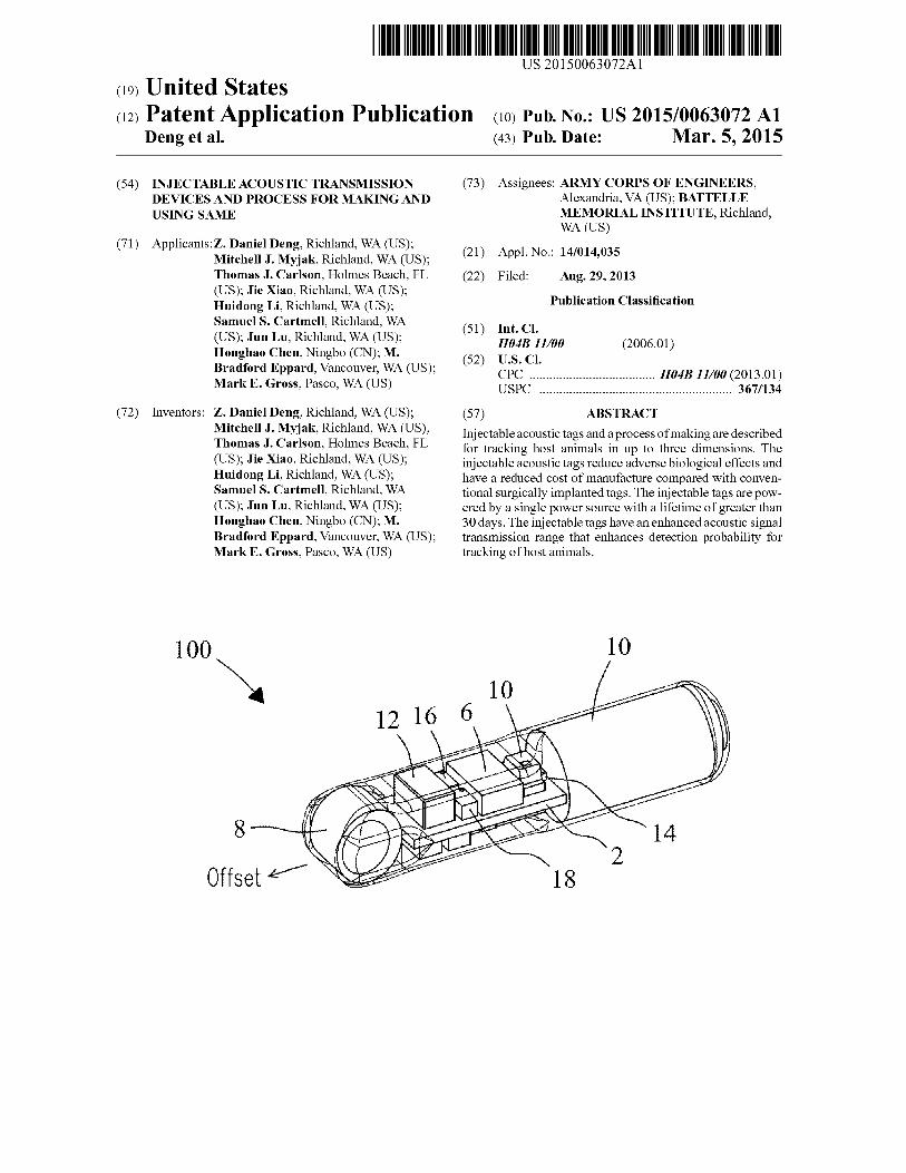
A)
Patent Application Publication Mar 5 2015 Sheet 7 of 10 US 20150063072 Α1
005
0
^ -005o_οldquo -01
CD cn
I -015gt
-02
-02500 02 04 06 08 10
Pulse Time (s)
f(
------ SR416------ ΜΒ306
τ---------------1---------------1-------------- r
FIG 7
Patent Application Publication Mar 5 2015 Sheet 8 of 10 US 20150063072 Α1
Offset Tube SI (dB) mdashmdash Regular Tube SL (dB)
FIG 8
Patent Application Publication Mar 5 2015 Sheet 9 of 10 US 20150063072 Α1
wreflector
FIG 9
Patent Application Publication Mar 5 2015 Sheet 10 of 10 US 20150063072 Α1
FIG 10
US 20150063072 Α11
Mar 5 2015
INJECTABLE ACOUSTIC TRANSMISSION DEVICES AND PROCESS FOR MAKING AND
USING SAME
STATEMENT REGARDING RIGHTS TO INVENTION MADE UNDER
FEDERALLY-SPONSORED RESEARCH AND DEVELOPMENT
[0001] This invention was made with Government support under Contract DE-AC05-76RL01830 awarded by the US Department of Energy The Government has certain rights in the invention
FIELD OF THE INVENTION
[0002] The present invention relates generally to acoustic tracking devices and systems More particularly the present invention relates to injectable acoustic transmission devices for detection and remote tracking of host animals in up to three dimensions in real-time or as a function of time
BACKGROUND OF THE INVENTION
[0003] Acoustic telemetry involves acoustic devices (acoustic tags) commonly used to monitor the behavior of eg marine and freshwater fish Acoustic tags transmit a sound signal or acoustic ldquopingrdquo that sends identification information and location information about a tagged animal to a receiver The receiver converts sound signals into digital data Post processing software processes the digital data and provides positions of the tag in up to three dimensions (3D) when at least four receivers detect the same sound signal By determining the soundrsquos time of arrival at the hydrophone receiver the position of the tagged animal can be determined allowing tracking of the host animal Then by tying the acoustic signature received from the transmitter to the proshygrammed signal code a specific animal may be identified An array of receivers allows the movement of particular animals to be tracked[0004] Acoustic telemetry has been identified as a technolshyogy for observation of behavior and assessment of survival for juvenile Chinook salmon passing through the Federal Columbia River Power System Considerable effort has been expended to understand the biological effects of implantation of acoustic tags in yearling and sub-yearling Chinook salmon Much additional effort has gone into development of autonoshymous and cabled receiving systems that can be deployed at dams and elsewhere in rivers Receiving systems detect sigshynals emitted by the acoustic tags process the resulting detecshytion data to track the fish and provide data necessary to estimate survival through dams and other routes of passage Together the acoustic tags and receiving systems in the Columbia River system make up the Juvenile Salmon Acousshytic Telemetry System (JSATS) Although acoustic tags presshyently used for JSATS meet current tag burden guidelines for most yearling Chinook salmon the tags are too large for smaller juvenile Chinook salmon particularly those found in the lower Columbia River and estuary that enter the river downstream of Bonneville Dam Bioeffects studies also indishycate that juvenile Chinook salmon less than 95 mm in length (approximately 9 g weight) implanted with current acoustic tags have reduced survival and growth rates Accordingly new tag designs are needed that reduce the overall size weight and volume enhance the range and lifetime reduce
adverse effects associated with implantation and broaden the range of potential applications The present invention addresses these needs
SUMMARY OF THE INVENTION
[0005] The present invention includes new injectable acoustic (sound-emitting) transmission devices (injectable acoustic tags) and a process of making Injectable acoustic tags of the present invention provide identification and remote tracking of host animals including fish eg in marine or freshwater environments in up to three dimensions (3D) (ie Χ-Υ-Ζ coordinates) in real-time or as a function of time Injectable acoustic tags may be used in applications such as eg fish survival studies monitoring fish migrationpassage trajectories tracking fish behavior in two dimensions (2D) or three dimensions (3D) measuring bypass effectiveness at dams and other passages observing predatorprey dynamics helping public utility agencies private firms and state and federal agencies meet fisheries regulations and other applishycations Compared to surgically implanted (ie non-inject- able) tags injectable tags of the present invention reduce bio-handling and enhance survivability of marine animals being tracked Injectable acoustic tags of the present invenshytion transmit location identification and sensor information in an encoded acoustic signal that propagates from the tag to an external receiver The encoded acoustic signal takes the form of one or more tag codes each tag code typically but not exclusively being transmitted at regular intervals Both the tagged animal and external receiver are typically located underwater but are not limited[0006] The injectable acoustic tags incorporate new advanced features compared to conventional acoustic tags One advanced feature of the injectable acoustic tags is the ability to transmit more than one tag code This feature increases the number of unique tag identifications (IDs) that may be transmitted in the acoustic signal while maintaining full backward compatibility with existing receiver equipshyment[0007] In some applications the injectable acoustic tag may alternate transmission between two tag codes In some applications tag codes may be identical[0008] Another advanced feature of the injectable acoustic tags is that each tag code is fully configurable including eg the bit length of the code (ie code length) and the number of acoustic pulses per bit for maximum application flexibility For example in some applications a shorter tag code may be used for acoustic transmissions close to the water surface to decrease undesirable multipath effects In other applications a longer tag code may be used to permit a greater number of unique tag identifications[0009] Yet another advanced feature of the injectable acoustic tags is the ability to embed temperature or other sensor data into at least one of the tag codes and to append the correct error checking bits to the tag code based on the encoded sensor data values For example in some applicashytions temperature data collected from a temperature sensor in the injectable acoustic tag may be transmitted as part of the tag code[0010] Sensors in the injectable acoustic tag may include accelerometers rotational velocity sensors magnetometers pressure sensors temperature sensors and combinations of these various sensors[0011] Yet another advanced feature of the injectable acoustic tags is the ability to configure both the acoustic
US 20150063072 Α12
Mar 5 2015
source level and acoustic transmission frequency This feashyture allows the battery life to be optimized for the application Each injectable tag maintains the acoustic source level at approximately the same level as the battery discharges which helps ensure consistency between data collected at different times[0012] Yet another advanced feature of the injectable acoustic tags is the ability to wait for a configurable amount of time before starting normal acoustic transmissions This waitshying period can be up to 30 days or more This feature is useful for tagging marine animals prior to their migration time The injectable tags can also be placed in a state that consumes minimal power so that the tags can be stored for a year or more before use[0013] The injectable acoustic tags have a reduced size weight and volume that exceeds source level outputs and lifetimes compared with conventional acoustic tags The reduced size weight and volume of the new tags permit study of animal species with sizes that are too small for current JSATS tags which broadens the range of applications The injectable acoustic tags are also less expensive to produce and use They also provide data and information suitable for development of animal-friendly hydro systems on an internashytional scale[0014] Components of the injectable acoustic tags may be encapsulated within a capsular containment structure (capshysule) made of a thermosetting polymer (eg an epoxide thershymosetting polymer) of various defined shapes that allows the tags to be injectable Internal volumes are less than about 115 mm3 In some applications injectable acoustic tags may include a length of about 15 mm and a diameter of about 34 mm[0015] In some applications injectable acoustic tags may have a dry weight of about 220 mg or less In some applicashytions injectable acoustic tags may contain a rigid printed circuit board with various electronics components attached [0016] Injectable acoustic tags of the present invention may be powered by a single custom power source or battery that delivers a source voltage output of from about 18 V to about 30 V The battery may provide a lifetime of greater than 35 days of full-time activity at a transmission pulse rate of 5 seconds and may provide a lifetime of at least 23 days of full-time activity at a transmission rate of 3 seconds The power source may have a mass of about 75 mg or less The power source may provide an energy density of at least about 230 Whkg[0017] The power source (battery) may include a plurality of laminates configured to supply an output voltage of at least about 25 volts Each laminate may include an anode and a cathode positioned between polymer separators that electrishycally isolates the cathode from the anode in the laminate The separator may include a micro-porous polypropylene The cathode may be include or be constructed of eg carbon fluoride and a conducting carbon within a binder affixed at a selected thickness to a current collector The binder may include eg polytetrafluoroethylene (PTFE) In some applishycations the cathode may include 85 wt carbon fluoride 10 wt carbon and 5 wt polytetrafluoroethylene (PTFE) binder The current collector may include a metal mesh of aluminum or an aluminum-containing alloy The anode may include lithium metal of a selected thickness and a selected weight The cathodeanode laminates may be enclosed within a container constructed of a high mechanical strength chemishycally resistant polymer of a selected thickness The power
source may be filled with an electrolyte The electrolyte may include a selected concentration of lithium hexafluorophos- phate (LiPF6) disbursed in a selected volume ratio of ethylene carbonate (EC) and dimethyl carbonate (DMC) that minishymizes voltage drops within the power source during operashytion[0018] Injectable acoustic tags may include one or more piezoelectric transducers The number of transducers is not limited Each piezoelectric transducer may vibrate at a selected resonant frequency which transmits an acoustic sigshynal containing encoded data from the piezoelectric transducer to a receiver[0019] Injectable acoustic tags may include a controller that couples to the power source and controls various circuits and functions within the acoustic tag In some applications the controller may be a microcontroller that contains a proshycessor core memory internal oscillators timers and proshygrammable input and output peripherals which executes embedded firmware (source code) that defines its operation [0020] Injectable acoustic tags may include a resonator crystal or other type of oscillator component to provide an external clock signal to the microcontroller The microconshytroller may use an external clock signal to help control the circuits on the tag that generate the acoustic signal The microcontroller may also use an external clock signal to help calibrate its internal oscillators and timers In some applicashytions the tag uses a ceramic resonator with a resonant freshyquency of about 10 MHz with about 05 precision[0021] Injectable acoustic tags may include an infrared (IR) sensor that couples to the controller and provides an optical link to a host computer located external to the acoustic tag The infrared sensor may receive programming and configushyration information from the host computer that configures the controller for operation of the tag (eg start transmission set the transmission frequency to 3 seconds and additional operations)[0022] Injectable acoustic tags may include a boost conshyverter circuit that couples to the controller and the power source The boost converter circuit may enhance the voltages from the power source (battery) and provides those voltages to the drive circuit that drives the piezoelectric transducer The boost converter circuit may enhance the voltage from the power source that is provided to the at least one piezoelectric transducer by up to about 6 volts[0023] Injectable acoustic tags may include a drive circuit that couples to the controller and to either the boost converter circuit or the power source The drive circuit may deliver a drive voltage to the piezoelectric transducers to generate vibration in one or more vibrational modes This process in turn generates the acoustic signal that is transmitted from the injectable acoustic tags[0024] The acoustic signal transmitted from the injectable acoustic tags may contain binary (or derivative) data encoded with phase-shift keying (PSK) The binary data may contain header bits (eg a Barker code) a tag identification (ID) code data collected from one or more sensors (eg temperashyture from a temperature sensor) error checking bits (eg a cyclic redundancy check) or combinations of any or all of the above The binary data within a single acoustic signal comshyprises one tag code The injectable acoustic tag may store one or more distinct tag codes[0025] The present invention also includes a method for transmission of identification and location information about a host animal in real-time or as a function of time The method
US 20150063072 Α13
Mar 5 2015
may include injecting an injectable acoustic transmission device of a selected size and shape at a selected location in the body of the host animal Location and identification data about the host animal may be transmitted from the injectable acoustic tag located within the body of the host animal to a receiver located external to the host animal as an acoustic signal encoded with one or more tag codes of a selected code length[0026] The acoustic signal when received from the injectshyable acoustic transmission device may be decoded to identify and track the host animal in up to three dimensions in realshytime or as a function of time The method may include proshygramming the injectable acoustic tag for operation via an optical link device in the tag The programming may include configuring the injectable acoustic tag to automatically adjust the output voltage of the power source to retain a full power level as the power source discharges as a function of time [0027] Injectable acoustic tags may be injected into the body of the host animal eg along the linea alba[0028] The receiver may be an acoustic hydrophone The acoustic signal from the piezoelectric transducer may be transmitted at a source level that is programmable which results in a selectable detection range The piezoelectric transducer may be of a spherical shell geometry or tube geomshyetry The outer wall and inner wall of the piezoelectric transshyducer may be coated with an electrode that permits the piezoshyelectric transducer to be coupled to the circuit board[0029] In some applications an acoustic reflector may be coupled to the piezoelectric transducer eg behind the piezoshyelectric transducer The reflection of acoustic waves enhances the acoustic signal transmitted from the piezoelectric transshyducer The acoustic reflector may be placed in direct contact with each individual piezoelectric transducer The acoustic reflector may reflect acoustic waves emitted from the back of the piezoelectric transducer which would otherwise propashygate towards or interfere with electronic components the battery or other components of the acoustic tag to achieve desired beam patterns[0030] In some applications the acoustic reflector may be fashioned of a porous material that is filled with a gas such as air[0031] In some applications the piezoelectric transducer may be an off-centered piezoelectric ceramic tube transducer or a spherical shell transducer in which the outer circumfershyence and inner circumference of the transducers are not conshycentric The inner circumference may be offset towards the desired direction of transmission to maximize the acoustic energy emitted in that direction[0032] In some applications the piezoelectric transducer may be polarized (activated) along the wall thickness direcshytion to produce a selected vibration at a selected resonance frequency For example when actuated by an AC voltage the piezoelectric transducer may vibrate in the radial direction that resembles a breathing motion ie the so-called ldquobreathshyingrdquo vibrational mode Yet vibrational modes are not limited Length mode and thickness mode may also be used either alone or in combination with ldquobreathing moderdquo[0033] In some applications the vibrational mode may be selected to be about 10 kHz to 50 kHz higher than the freshyquency of the drive signal that drives the transducer Higher resonance frequencies can compensate for downshifts in the transducer frequency caused by the coating surrounding the transducers
[0034] Injectable acoustic tags may be programmed to transmit one or more encoded identification (ID) codes Each tag code may include a code length of up to 64 binary bits The controller may coordinate the timing and transmission of each of the tag IDs alternating transmission of eg a first tag ID and a second tag ID In some applications only a single tag code ID may be desired Format of the tag codes is selectable In some applications one of the tag IDs may be configured to transmit data from various sensors incorporated into the injectable tag[0035] The coding may include configuring the number of cycles required per bit of data transmitted from the injectable acoustic transmission device The coding may include proshygramming the injectable acoustic transmission device to transmit the one or more identification codes within the acoustic signal transmitted from the injectable acoustic transshymission device[0036] The foregoing summary is neither intended to define the invention which is measured by the claims nor to be limiting as to the scope of the invention in any way
BRIEF DESCRIPTION OF THE DRAWINGS
[0037] FIGS la-lc show different views of an embodiment of the present invention[0038] FIGS 2a-2c show different views of an offset piezoshyelectric transducer of the present invention[0039] FIG 3a is a block diagram showing electrical comshyponents of an embodiment of the present invention[0040] FIG 3b is a circuit diagram of one embodiment of the present invention[0041] FIG 4 is a cross-sectional view of a power source of the present invention[0042] FIG 5 compares resistances for a power source of the present invention against a conventional power source at temperatures ranging from -5deg C to 25deg C[0043] FIGS 6a-6b compare the transmitter pulse current for the power source of the present invention against a conshyventional power source at 25deg C and 0deg C respectively [0044] FIG 7 compares the voltage drop for the power source of the present invention against a conventional power source during a pulse transmission at 0deg C[0045] FIG 8 compares beam patterns for an offset (ηοη- concentric) piezoelectric transducer of the present invention against a conventional (concentric) piezoelectric transducer [0046] FIG 9 compares beam patterns of injectable tags of the present invention that include various spacing widths positioned behind the piezoelectric transducers[0047] FIG 10 shows a top and a bottom portion of an injection mold for encapsulation of injectable tags of the present invention
DETAILED DESCRIPTION
[0048] New injectable acoustic transmission devices (inshyjectable acoustic tags) and a process of making are detailed that provide identification and remote tracking of marine or freshwater animals including fish in water environments in up to three dimensions (3D) (ie Χ-Υ-Ζ coordinates) in realshytime or as a function of time Features of the injectable acousshytic tags can be tailored for various unique applications and projects Studies may be conducted in lakes rivers tributarshyies estuaries and at sea The following description includes a best mode of the present invention While the present invenshytion is susceptible of various modifications and alternative
US 20150063072 Α14
Mar 5 2015
constructions it should be understood that there is no intenshytion to limit the present invention to specific forms disclosed herein but on the contrary the present invention is to cover all modifications alternative constructions and equivalents falling within the scope of the present invention as defined in the claims Therefore the present description should be seen as illustrative and not limiting Additional features of the present invention are detailed by Deng et al in a document entitled ldquoJSATS Injectable Acoustic Transmitter Reference Design Documentationrdquo prepared by the Pacific Northwest National Laboratory (Document No PNNL-22372) for the US Army Corps of Engineers Portland District March 2013 which reference is incorporated herein in its entirety [0049] FIG la illustrates a top view of an injectable acousshytic (sound-emitting) transmitter device (tag) 100 in assembled form showing exemplary components While varishyous components are described herein components and conshyfiguration are exemplary and not limited For example in various embodiments injectable acoustic tags of the present invention may include various form factors and shapes that allow the tags to be injectable and tailored for selected applishycations ldquoForm factorrdquo refers to the physical arrangement configuration and dimensions of components in the injectshyable acoustic tags including but not limited to eg circuit boards piezoelectric transducers controllers acoustic reflecshytors inductors capacitors diodes and capsules In some embodiments injectable tag 100 may have a generally elonshygated or cylindrical shape that permits the tag to be injectable into the host animal but shapes are not intended to be limited Components of tag 100 may be encapsulated within a coating that defines a capsule 4 Capsule 4 may be composed of a thermosetting polymer such as an epoxy (eg EPO-TEKreg 301 epoxy Epoxy Technology Inc Billerica Mass USA) or a resin (eg Electrical Resin 53Μ Company St Paul Minn USA) Capsule 4 may include an exemplary length of about 15 mm but length is not limited Diameter of capsule 4 at the widest point along the length may be about 34 mm Final weight may be at or below about 228 mg[0050] In various embodiments selected components of tag 100 may be mounted onto a circuit board 2 constructed of suitable or selected circuit board materials available commershycially (eg Sierra Circuits Inc Sunnyvale Calif USA) Circuit board 2 materials may include but are not limited to eg a rigid material such as FR4 board with a thickness of about 0008 or flexible materials such as flex board with a thickness of about 0003 In various embodiments circuit boards 2 of tag 100 may be configured with both a top side and a bottom side each side of circuit board 2 configured with selected electrical circuits andor device components Circuit board 2 may include exemplary spacing widths and copper line widths for electrical circuits of about 0003 but are not limited As will be appreciated by those of ordinary skill in the art circuit configurations and associated designs and tag components may be altered without departing from the spirit and scope of the present invention Thus no limitations are intended[0051] Injectable tag 100 may include a controller 6 that controls operation of components and circuits of the tag A piezoelectric transducer 8 may be positioned at a forward end of the tag so that the acoustic signal may be transmitted from the tag without encountering interference from tag composhynents such as an inductor 12 or other components of the tag In the figure piezoelectric transducer 8 is shown electrically coupled to circuit board 2 but does not need to reside on
circuit board 2 A power source 10 may be coupled to circuit board 2 to power components of the injectable tag In some embodiments power source 10 may be positioned at an end opposite to piezoelectric transducer 8 to minimize any potenshytial blockage of the acoustic signal caused by the physical size of the power source 10 Flowever location is not limited A capacitor 14 (eg a 1 pF capacitor) may act as a decoupling capacitor for the power source to help smooth any electrical noise A first MOSFET transistor 16 may form part of a boost converter circuit described further herein A second MOSshyFET transistor 18 and an inductor 12 (eg a 100 μΕ1 inductor) may form a drive circuit described further herein A phoshytotransistor 20 sensitive to infrared radiation may provide an optical link to an external programmer module (FIG 3b) for receipt of commands that configure microcontroller 6 for operation[0052] FIG lb illustrates a bottom view of injectable acoustic transmission tag 100 showing exemplary composhynents on a bottom side of circuit board 2 A capacitor 22 (eg a 22 pF capacitor) an inductor 26 (eg a 47 μ1Τ inductor) and a diode 30 (eg a Schottky diode) together form part of a boost converter circuit described further herein A resonator 24 (eg a 10 MFlz ceramic resonator) may couple to the microcontroller (FIG la) to produce a clock signal for conshytrolling the operation of that microcontroller A resistor 28 (eg a 1 ΜΩ resistor) may couple to the resonator to help stabilize the clock signal[0053] FIG lc shows an injectable acoustic transmission tag 200 of a ldquobaseball batrdquo capsule design In the instant embodiment components of the tag are encapsulated in a capsule 4 that has an appearance of a baseball bat with a narrowed front end (the ldquohandlerdquo of the ldquobatrdquo) and a power source 10 positioned at a back end of the capsule (the ldquohitting endrdquo of the ldquobatrdquo) The narrowed front end reduces the weight and volume of injectable acoustic transmission tag 200 Capshysule 4 may have an exemplary length of about 15 mm but is not limited Diameter of tag 200 at the widest point along the length of the capsule (ie at the location of the power source 10) is about 34 mm Average weight may be between about 216 mg and about 218 mg when EPO-TEK 301 epoxy or 3Μ Electrical Resin 5 is used as the coating material[0054] FIG 2a shows a top view of a piezoelectric tube transducer 8 of an offset inner circumference (IC) design Piezoelectric transducer 8 converts electrical energy from the power source (FIGS la-lc) into ultrasonic energy (ie an acoustic signal) that is transmitted to a receiver (not shown) Piezoelectric transducers 8 may be constructed of any suitshyable piezoelectric ceramic material including eg lead zir- conate titanate (ΡΖΤ) lead magnesium niobate-lead titanate (ΡΜΝ-ΡΤ) or lead-free ceramic materials such as sodium potassium niobate (ΚΝΝ) and bismuth sodium titanate (ΝΒΤ) IC-offset piezoelectric transducer 8 may include an inner wall 32 and an exterior (outer) wall 34 that are not concentric The circumference of inner wall 32 may be offset from the center position of exterior wall 34 When assembled into the injectable tag the IC-offset piezoelectric transducer 8 may be oriented with the thinnest portion of the transducer wall facing the front of the tag The offset maximizes energy delivered from the piezoelectric transducer in the direction of the offset Dimensions of piezoelectric transducer 8 may be tailored to provide a selected operation frequency Frequenshycies are not limited In some embodiments the resonance frequency is selected to be about 4167 kHz In the instant embodiments IC-offset piezoelectric transducer 8 may
US 20150063072 Α15
Mar 5 2015
include an exterior (outer) wall 34 with an OD of about 24 mm to about 26 mm an inner wall 32 with an ID of about 17 mm to about 19 mm and a thickness in the offset direction of about 015 mm Dimensions of piezoelectric transducer 8 may include a tolerance at least about plusmn005 mm In some embodiments piezoelectric transducer 8 may have a resoshynance frequency about 10 kHz to 50 kHz higher than the frequency of the drive signal that drives piezoelectric transshyducer 8 The higher frequency compensates for frequency downshifts that may be caused by the epoxy or resin coating on the piezoelectric transducer
[0055] FIG 2b is a schematic showing the acoustic transshymission device 100 in assembled form configured with an inner circumference (IC)-offset piezoelectric transducer 8 positioned at a front end of the device a power source (batshytery) 10 at a back end of the device and a circuit board 2 in the middle section IC-offset piezoelectric transducer 8 may include an inner wall 32 with an inner circumference (IC) and an exterior (outer) wall 34 that are offset in the forward transmission direction The offset may enhance the source level of the acoustic signal when the piezoelectric transducer is polarized (activated) along the thickness direction Piezoshyelectric transducer 8 may include a closed-cell foam 9 comshyposed of eg EPDM rubber ora like elastomer positioned so as to be bounded by inner wall 32 of piezoelectric transducer 8 that enhances acoustic properties of piezoelectric transshyducer 8 Dimensions of IC-offset piezoelectric transducer 8 are selected that maximize the transmission range of the acoustic signal IC-offset piezoelectric transducer 8 is prefshyerably oriented so that the direction of the IC-offset is directly pointed towards a receiver (hydrophone) (not shown) that detects the acoustic signal emitted by the piezoelectric transshyducer 8 but is not limited
[0056] FIG 2c shows a schematic of an injectable acoustic transmission device 200 of a baseball bat design In the figure piezoelectric transducer 8 may include an inner wall 32 and an exterior (outer) wall 34 that are concentric or that are offset as detailed previously herein Injectable tag 200 may also include an acoustic reflector 36 attached behind piezoelectric transducer 8 in front of power source (battery) 10 and circuit board 2 Acoustic reflector 36 reflects acoustic signals emitted from piezoelectric transducer 8 and enhances transmission in the forward direction from the acoustic (tag) 200 as detailed further herein In some embodiments acoustic reflector 36 may include or be composed of an ultra-low density material such as EPDM closed-cell (-03 mm thick) foam which may be attached to the back surface of piezoelectric transducer 8 in front of circuit board 2 The foam introduces an interface with a laige acoustic impedance mismatch greater than about 20x10s kg(m2-s) that redirects acoustic energy towards the front end of injectable tag 200 In addition acoustic reflector 36 enhances the source level of the acoustic energy output from piezoelectric transducer 8 along the forward 180 degree wavefront by at least a factor of about 05 dB to about 1 dB on average but acoustic eneigy values are not intended to be limited In various embodiments acoustic reflector 36 may include various selected thicknesses In some embodiments width of acoustic reflector 36 may be below about 15 mm to avoid blocking acoustic signals emitted from the two (ie left and right) sides of piezoelectric transducer 8 Thickness of acoustic reflector 36 depends in part on the size of the pores within the closed-cell foam Thickness is preferably 2 to 3 times the size of pores within the reflector material to ensure
acoustic waves encounter EPDMair interfaces within the reflector foam at least once in order to maximize effectiveness of the reflector[0057] Piezoelectric transducer 8 may include a closed-cell foam 9 composed of eg EPDM rubber or a like elastomer positioned so as to be bounded by inner wall 32 of piezoelecshytric transducer 8 that enhances acoustic properties of piezoshyelectric transducer 8 In some embodiments piezoelectric transducer 8 may include end caps 38 of a selected thickness (eg -02 mm) positioned at respective flat ends of transshyducer 8 End caps 38 may include or be composed of a selected metal such as copper (Cu) metal End caps 38 may be bonded to piezoelectric transducer 8 using eg a non-con- ductive epoxy End caps 38 can serve to enhance the source level of the acoustic signal emitted from flat ends of transshyducer 8[0058] FIG 3α is a block diagram showing various composhynents of injectable acoustic tags of the present invention Tags may include a controller component 6 (eg a 6-pin microshycontroller) The term ldquomicrocontrollerrdquo does not imply or limit selected dimensions for this component A ceramic resoshynator 24 may be coupled to microcontroller 6 and used to generate a clock signal for coordinating operation of various circuits An infrared sensor 20 may provide an optical link that receives and delivers configuration commands from an external infrared programmer module (FIG 3b) to controller 6 Configuration commands may specify various parameters for the operation of the microcontroller including but not limited to eg tag codes period between transmissions and other operation parameters A boost converter circuit 40 enhances voltages from power source 10 and delivers the enhanced voltages to a drive circuit 42 Drive circuit 42 drives piezoelectric transducer 8 to transmit an encoded acoustic signal at a specified frequency as detailed further herein [0059] FIG 3b shows an exemplary block diagram illusshytrating circuits and associated device components for injectshyable acoustic tags of the present invention Components described hereafter provide reduced physical dimensions and weights to the tag and allow circuits to operate at comparashytively high efficiencies given their smaller sizes However components are not intended to be limited All components as will be selected by those of ordinary skill in the art in view of the description are within the scope of the present invention No limitations are intended[0060] Injectable acoustic transmission devices (tags) of the present invention may include a controller (Ul) 6 (eg a model PIC16F1823TCL 8-bit 8Κ flash programmable microcontroller in a chip-scale package Microchip Techshynologies Chandler Ariz USA) with a low current draw (eg 20 ηΑ in sleep mode or 300 ηΑ in sleep mode with the watchdog timer active) Controller 6 is a programmable comshyponent that controls operation of circuits and electrical comshyponents within injectable acoustic tag 100 Controller 6 may operate from input voltages between about 18 V and about 36 V Selected voltages are compatible with a power source (battery) 10 Controller 6 may include modules or composhynents such as eg an internal oscillator sleep mode inter- rupt-on-change capability a fixed voltage reference a temshyperature sensor timers pulse width modulators and a Universal Asynchronous ReceiverTransmitter (UART) Controller 6 generates control signals for both a boost conshyverter circuit 40 and a drive circuit 42[0061] Power source (battery) 10 may be connected to tershyminals (J4) 46 and (J5) 48 on either each side of circuit board
US 20150063072 Α16
Mar 5 2015
2 during assembly Piezoelectric transducer 8 may be conshynected to terminals (J3) 50 and (Jl) 52 on opposite sides of circuit board 2 at an end opposite power source 10 A bypass (or decoupling) capacitor (C2) 14 (eg a model AMK063ABJ105MP-F 1-pF 4V X5R 20 0201 tantalum capacitor Taiyo Yuden Co Ltd Schaumburg 111 USA) may be used to help filter any electronics noise on power source 10 and reduces maximum peak currents drawn from power source 10 when controller 6 or boost converter circuit 40 draws current
[0062] A resonator (Yl) 24 (eg a modelCSTCE10M0G52-R0 100 MHz SMD ceramic resonator Murata Manufacturing Co Ltd Nagaokakyo Kyoto Prefecshyture Japan) may be coupled on the input side of controller 6 to generate a precise clock signal with a selected precision (eg plusmn05 precision) Controller 6 may use the clock signal to generate control signals for boost converter circuit 40 and drive circuit 42 Due to the 10 MHz rating of resonator (Yl) 24 control signals for drive circuit 42 permit the circuit to generate an acoustic signal at desired modulation frequenshycies eg 4167 kHz Control signals generated by controller 6 can be synchronized to 4167 kHz when controller 6 uses the clock signal as its input timing source The clock signal controls and modulates the (modulation) frequency of piezoshyelectric transducer 8 A resistor (Rl) 28 (eg a model CRCW02011M00FKED 10 ΜΩ V20 W 5 0201 SMD resistor Vishay Intertechnology Inc Malvern Pa USA) may be placed in parallel with resonator 24 to reduce startup time and improve stability of the generated clock signal
[0063] A unidirectional infrared sensor or phototransistor (Ql) 20 (eg model ΡΤ19-21Β Flat Black Mini (3-mm) SMD Phototransistor Everlight Electronics Co Ltd Taipei Taishywan) may couple to controller 6 using an input pin such as a UART pin (not shown) configured with ldquointerrupt-on- changerdquo capability that produces an interrupt upon a positive andor negative change in logic level Pin selections are not limited
[0064] Phototransistor 20 is sensitive to infrared light and provides an optical link that may be used to interface the inj ectable tags to an external infrared Integrated Circuit Serial Programmer (ICSP) module (Programmer) 56 (eg a MPLABICD 3 programmer Microchip Technologies Chanshydler Ariz USA) Programmer module 56 may load configushyration and programming information including firmware code into controller 6 Programmer 56 may connect to an RS-232 serial port (not shown) of a host computer (not shown) The external infrared programmer module may include an infrared LED (not shown) that indicates when the programmer is ldquoonrdquo or ldquooffrsquo For example the LED is ldquoonrdquo when the transmit line is logic 0 (positive voltage) and ldquooffrsquo when the transmit line is logic 1 (negative voltage) Writing bytes to the serial port of the host computer transmits those bytes across the infrared link 20 (ie from the infrared LED to phototransistor 20) into the tag controller 6 The infrared link 20 provides no direct feedback to the host computer
[0065] Phototransistor 20 when activated by infrared light receives configuration commands through the optical link and transfers the commands to controller 6 Delivery of conshyfiguration commands into controller 6 configures various parameters of the tag including eg tag codes transmission period and other parameters for operation prior to or followshying injection of the tag into the host animal The infrared link
is reliable simple requires a minimum number of composhynents and avoids false triggering problems after injection of the tag into the host animal[0066] Data transmission protocol over infrared link 20 may consist of a 2-second serial break followed by a stream of bytes The serial break turns on the infrared LED on infrared programmer module 56 for an extended period of time so that microcontroller 6 may sense the infrared light and prepare to configure parameters The stream of bytes may consist of an initial check byte a byte that indicates the total number of data bytes in the transmission and the selected data bytes Data bytes may specify values for the internal microcontroller parameters in a predefined order The host computer may run an exemplary MATLAB (MathWorks Inc Natick Mass USA) software program that delivers configuration informashytion through a serial port into the infrared programmer While MATLAB is described other computer programming lanshyguages may be used No limitations are intended[0067] In some embodiments phototransistor 20 provides atransferrateofabout300baud However parameter transfer rates are not intended to be limited Phototransistor 20 genshyerally operates as a simple pull-down transistor triggered by infrared light Controller 6 may activate a weak internal pull- up resistor to generate a logic high input on the input pin (eg a UART pin) when phototransistor 20 is not activated Conshytroller 6 may disable phototransistor 20 to save power by driving the input pin to ground[0068] Boost converter circuit 40 enhances voltages output from power source (battery) 10 into higher voltages Drive circuit 42 may use these higher voltages to drive piezoelectric transducer 8 Boost converter circuit 40 may include an inductor (LI) 12 (eg a model GLFR1608T470M-LR 47 μΗ 35 mA 20 0603 inductor TDK Corp New York ΝΥ USA) that stores magnetic energy as an electronic current a MOSFET transistor (Q2) 16 (eg a model PMZ390UN N-channel type 30V 178 A SOT-883 MOSFET Fairchild Semiconductor San Jose Calif USA) that switches on and off repeatedly a diode (Dl) 30 (eg a model SDM02U30LP3 30V diode Diodes Incorporated Plano Tex USA) that conducts current primarily in one direction toward the output and a capacitor (Cl) 22 (eg a model 298D226X0010Μ2Τ 22-pF 10V 20 0603 tantalum capacitor Vishay Sprague Malvern Pa USA) that stores an elevated voltage MOSFET transistor (Q2) 16 is coupled to the output of controller 6[0069] When transistor (Q2) 16 is switched ldquoonrdquo by conshytroller 6 current begins to increase in inductor (L2) 26 When transistor (Q2) 16 is switched back ldquooffrsquo by microcontroller 6 current from inductor (LI) 12 is delivered through diode (Dl) 30 into capacitor (Cl) 22 which charges capacitor (Cl) 22 Controller 6 may switch transistor (Q2) 16 ldquoonrdquo and ldquooffrsquo a selected number of times to charge capacitor (Cl) 22 to a desired value Capacitor (C1) 22 may have a minimum rating of about 10 V and a capacitance of at least about 22 pF to minimize voltage drops while drive circuit 42 is drawing current Boost converter circuit 40 delivers a suitable drive voltage (HVDD) 58 as an input to drive circuit 42[0070] A drive circuit 42 may be coupled on the output side of microcontroller 6 to facilitate transmission of the acoustic signal from piezoelectric transducer 8 Drive circuit 42 may define the signaling levels and signaling approach of the injectable tag Drive circuit 42 may include an inductor (L2) 26 (eg a model BRL2012T101M 100 μΗ 85 mA 20 SMD Inductor Taiyo Yuden Co Ltd Schaumburg 111 USA) that
US 20150063072 Α17
Mar 5 2015
stores magnetic energy as an electronic current and a MOS- FET transistor (Q3) 18 (eg a model PMZ390UN N-channel type 30V 178 A SOT-883 MOSFET Fairchild Semiconducshytor San Jose Calif USA) that switches on and off Transistor (Q3) 18 maybe coupled to an output pin of controller 6 Drive circuit 42 may attach to terminals (J1) 50 and (J3) 52 of circuit board 2 Voltage at connector 52 is tied to elevated voltage (HVDD) 58[0071] When transistor (Q3) 18 is switched ldquoonrdquo by microshycontroller 6 current begins to increase in inductor (L2) 26 Voltage at connector 52 may be set to ground When transistor (Q3) 18 is then switched ldquooffrsquo by microcontroller 6 inductor (L2) 26 and piezoelectric transducer 8 conceptually form a resonant LC circuit Voltage at connector 52 of piezoelectric transducer 8 may oscillate at a frequency determined by the inductance of inductor (L2) 26 and the characteristic capacishytance of piezoelectric transducer 8 Oscillation frequency may be greater than the desired modulation frequency of the acoustic signal Voltage on connector 52 may increase above drive voltage (F1VDD) 58 and then return to near ground Transistor (Q3) 18 may be switched back ldquoonrdquo by microconshytroller 6 to prevent further oscillations from taking place in piezoelectric transducer 8 Voltage differences across piezoshyelectric transducer 8 connected between terminal 50 and tershyminal 52 may thus range between negative and positive valshyues[0072] Controller 6 may switch transistor (Q3) 18 ldquoonrdquo and ldquooffrsquo in a particular pattern so that drive circuit 42 can apply the desired electrical signals to the piezoelectric transducer and generate the correct acoustic waveform To transmit a series of acoustic pulses representing one bit of the tag code microcontroller 6 may apply a square wave to transistor (Q3) 18 with the desired modulation frequency (eg 4167 kFlz) The duty cycle of the square wave is typically 33 so that transistor (Q3) 18 is switched ldquoonrdquo for one-third of each modulation period and inductor (L2) 26 and piezoelectric transducer 8 are allowed to oscillate for two-thirds of each modulation period When transitioning from a logic ldquo0rdquo bit to a logic ldquo1rdquo bit or vice versa microcontroller 6 may delay a next pulse by a time period that is one-half of a modulation period This procedure produces an acoustic signal from piezoelectric transducer 8 that includes encoded binary data implemented eg by way of phase-shift keying (PSK) [0073] In various embodiments separate MOSFET transisshytors (Q2) 16 and (Q3) 18 may be used rather than a single dual-channel MOSFET transistor to facilitate layout and design on circuit board 2 but is not intended to limited thereto Further components on circuit board 2 described herein may be placed in close proximity to minimize length of the tags For example resonator 24 and inductor (L2) 26 may be in contact after board assembly without problems since resonator 24 has a perimeter surrounded by a nonconductive material[0074] FIG 4 shows a cross-sectional view of the custom power source (battery) 10 (termed ΜΒ306 hereafter) that supplies power to acoustic transmitter (tag) (FIGS la-lc) and electrical components of the present invention Battery 10 may include a cathode 62 that includes a composite of carbon monofluoride as an active cathode material mixed with a conductive carbon in a binder such as polytetrafluoroethylene (PTFE) to form a free-standing electrode In an exemplary embodiment composite cathode 62 may include 85 wt active cathode material 10 wt conductive carbon (eg SUPER-Preg conductive carbon Timcal Ltd Bodio Switzershy
land) and 5 wt PTFE The composite cathode material when dried may be introduced (eg pressed) onto a current collector support 64 constructed of aluminum (or other metal) mesh to form the composite cathode electrode 62 Current collector 64 provides electron transfer between respective cathode 62 and anode 72 electrodes in battery 10 A metal lead 66 [eg positive (+) lead] constructed eg of enameled copper wire (eg 013 mm OD)] which may be soldered to current collector 64 Composite cathode 62 (with or without a copper wire lead 66) may be divided into sections with selected dimensions Individual cathode sections 62 may be introduced between two layers of a separator 70 material composed eg of a micro-porous polypropylene (eg Sepashyrator 2500 Celgard LLC Charlotte NC USA) that electrishycally isolates cathode 62 from anode 72 in individual cathode anode laminates (couples) 74 Anode 72 may include or be composed of lithium metal [FMC lithium Charlotte NC USA] with selected thicknesses In some embodiments thickness of the anode 72 may be about 015 mm but is not limited An anode lead 68 (eg 013 mm OD) may be constructed of eg copper and coupled to anode 72 by directly pressing lead 68 onto the lithium metal[0075] Multiple individual electrochemical cathodeanode couples (laminates) 74 each comprising a cathode 62 and an anode 72 may be bundled together and introduced into a container 76 In various embodiments laminates 74 may include a thickness between about 021 mm and about 024 mm but dimensions are not intended to be limited Container 76 may be of a generally cylindrical shape and constructed of a high strength material such as a fluoropolymer eg ethylshyene tetrafluorethylene (ETFE) sold commercially under the tradename TEFZELreg (DuPont Wilmington Del USA) or aluminum The polymer includes a high melting temperature a high flow rate and excellent chemical and electrical resisshytance properties With laminates 74 introduced into container 76 container 76 may be filled with an electrolyte 78 (up to 35 mg on average) to minimize time delays characteristic of conventional CF electrochemical cells In various embodishyments electrolyte 78 may include or be composed of eg 1Μ lithium hexafluorophosphate (LiPF6) that is disbursed in a 11 volume ratio [ECDMC] of ethylene carbonate (EC) in dimethyl carbonate (DMC) Container 76 may then be capped with a polymer lid 80 after inserting wire leads 66 and 68 through holes (not shown) introduced in lid 80 Battery 10 when assembled may be sealed eg with an epoxy or other thermosetting polymer TABLE 1 shows physical properties of the battery of the present invention compared against conshyventional (SR416) silver oxide (Qty=2 stacked) batteries
TABLE 1
lists typical physical properties of the ΜΒ306 battery compared with conventional silver oxide batteries
BatteryDiameter Length Volume
PackageContainer
Weight(mg)
WallThickness
TotalWeight
(mg)ΜΒ306 30 60 42 17 015 75SR416 48 32 58 na na 260(Qty 2)
[0076] As shown in the table battery 10 may have an outer diameter of 30 mm and a length of 60 mm (tolerance plusmn02 mm) Thickness of the wall of battery 10 capsule wall and lid
US 20150063072 Α18
Mar 5 2015
is about 015 mm but is not limited The battery has a low mass [approximately 0075 g (plusmn002 g)] and a low volume [approximately 0042 cm3] Current weight of the battery represents -71 reduction in the weight burden for tagged animals compared with prior art designs TABLE 2 compares performance properties of the ΜΒ306 battery against comshymercial silver oxide batteries
TABLE 2
lists typical operating and performance parameters of the ΜΒ306 battery
Impedance((a) 1 kHz) Total
Open Circuit Voltage (OCV) ocv
ccv(43 kQ
lead)
Capacity(Cut-off15V) Enersv Density
(Volts) (Ω) (Ω) (mAh) Whkg WhL
285-325 le200 6-10 ~73 231 408
[0077] Battery 10 may include a discharge rate of about 86 mAg (1 mAcm2) at 23deg C Cut-off voltage may be about 15 V Battery 10 may also deliver a gravimetric energy density of 231 Whkg (volume energy density of 408 WhL) an enhancement of greater than 133 over conventional SR416 batteries In operation battery 10 may also deliver a stable output voltage of at least 285 volts and stable pulse current over a wide temperature range from 0deg C to 25deg C This output voltage is nearly 1 V higher than commercial 416 batteries which removes the need to stack batteries as in prior JSATS transmitters or the need for extra electronics to achieve a 3 V output Battery 10 may also have an intrinsically lower impedance compared with SR416 cells used in prior art JSATS transmitters FIG 5 compares the impedance of the battery of the present invention against conventional SR416 cells Data show the performance of the battery of the present invention is superior to SR416 cells over a wide temperature range from-5deg C to 25deg C and beyond Additional aspects of the power source are detailed by Chen et al in a publication entitled ldquoMicro-Battery Development for Juvenile Salmon Acoustic Telemetry System Applicationsrdquo which reference is incorporated herein in its entirety[0078] Battery 10 may provide a long service lifetime and steady voltage performance forthe active transmission device compared to conventional transmitters known in the art that employ dual SR416 cells Lifetimes of the power source 10 are selectable based on the selection of pulse rate (current) intervals (PRIs) Pulse currents are not limited In some embodiments for example the battery may be configured to deliver a pulse current (PRI) every 3 seconds providing an active lifetime rating of at least 20 days In some embodishyments the battery may be configured to deliver a pulse current (PRI) every 5 seconds providing an active lifetime rating of
at least 30 days Longer lifetimes may be selected 7 seconds 40 days and 10 seconds 60 days No limitations are intended [0079] FIG 6a compares pulse currents (mA) generated by the ΜΒ306 battery of the injectable tags at 25deg C and 0deg C FIG 6b compares pulse currents generated by conventional silver oxide batteries at 25deg C and 0deg C Results show amplishytudes of pulse currents of the ΜΒ306 battery are both greater and delivered more rapidly than those obtained with silver oxide cells[0080] FIG 7 compares cell voltages for the ΜΒ306 batshytery upon a pulse transmission at 0deg C against conventional SR416 silver oxide cells Data show that voltage drops forthe SR 416 cells are about a factor of two greater at low temperashytures compared with the ΜΒ306 battery When in an inactishyvated state the injectable acoustic tag of the present invention maintains a battery capacity of greater than 85 for 12 months after assembly when stored at room temperature (23deg C)
Controller Firmware[0081] Source code loaded into the controller (FIG 3a) memory may be used to control the functionality and operashytion of the injectable acoustic tag Source code may be proshygrammed (eg using the MPLAB integrated development environment or like software tools) on a host computer in assembly language (eg PIC assembly language) or a higher level language (eg C programming language) The software tools on the host computer create the firmware eg in binary or derivative code (eg hexadecimal or hex) that can be programmed into the controller on the circuit board (FIG 1) Source code may be divided into various exemplary modules including but not limited to main specifies configuration bits declares variables and executes initial instructions after the controller is reset initialize clears all working variables calibrate calibrates timers (eg the watchdog timer) used to set the transmission frequency waiting periodically checks the infrared sensor until the tag is configured storage keeps the infrared sensor active until the tag is configured hibershynate waits for a specified amount of time (eg 30 days) before starting acoustic transmission running waits for a specified period (eg 3 seconds) between acoustic transmisshysions transmit activates the boost converter circuit (FIG 3a) and the drive circuit (FIG 3a) to generate the desired acoustic signal on the piezoelectric transducer (FIG 1) program reads configuration data from the infrared link and sets the operating mode and other parameters debug contains code for development purposes and tables contains lookup tables for performing arithmetic operations required to compute temperatures or other sensor data Controller firmware may contain one or more parameters that control the functionality and operation of the tag These parameters may be initialized to default values when the microcontroller powers up for the first time and later configured to new values via the infrared link TABLE 3 lists exemplary parameters that may be stored in the controller memory to control operation of the injectable acoustic transmission devices (tags)
TABLE 3
lists exemplary parameters in controller memory with associated memory requirements for operation of injectable acoustic transmission devices (tags)
NAME BYTES DESCRIPTION
NextState 1 Specifies the operating mode of the controller The state containsa series of bits whose functions are explained in the source code Common values are as follows04 hex place controller in waiting mode 08 hex place controller in storage mode
US 20150063072 Α19
Mar 5 2015
TABLE 3-continued
lists exemplary parameters in controller memory with associated memory requirements for operation of injectable acoustic transmission devices (tags)
NAME BYTES DESCRIPTION
Runlnterval 2
11 hex calibrate then hibernate then transmit21 hex calibrate then transmitPulse rate interval in units of 65536 ms The least significant byte
HibeTotal 2
is first For short pulse rate intervals the value may be decreased to compensate for delays in the controllerHibernate duration in units of 19089 hr The least significant byte
ChrgTable 6is firstA table of charge durations vs battery voltage in units of 2048 ps
Cal Interval 2
A first value specifies charge duration of the boost converter for a lowest range of battery voltages A second value may specify charge duration for a second lowest range of battery voltages etc Higher values result in a higher source level but also increase energy consumption The relationship may be characterized empiricallyNumber of transmissions between calibrations Controller may
XmitCycles 1
calibrate timers to ensure that pulse rate interval remains accurate The same parameter value may be used in hibernate mode to specify number of 256-second intervals between calibrations The least significant byte may be firstCycles per bit minus two The value should be 8 for backward
Xmitlnsert 1compatibilityIndex to insert temperature and CRC (check code) in tag code Β
XmitState 1
or ldquo0rdquo if no insertion is performed Temperature may use 5 bits and CRC may use 8 bitsParameter may be ldquo0rdquo when changing XmitCode values
XmitCode 64 Table of transmit codes Each value specifies one bit of tag code
CRC Table 32
A and one bit of tag code Β as listed below where bit 0 is theleast significant bitbit 0 transmit bit for code Abit 1 contains 1 at the last bit position for code Abit 4 transmit bit for code Βbit 5 contains 1 at the last bit position for code ΒTable of CRC codes that correspond to various temperatures
Sensor Data
[0082] Controller (FIG 3a) may contain an internal temshyperature sensor The controller may embed a 5-bit temperashyture value (or other sensor value of possibly different length) within one or more tag codes that are transmitted by the piezoelectric transducer to the receiver Due to the manner in which the controller compensates for variations in the battery voltage the temperature sensor output may output a numeric value from 0 to 31 that varies with temperature but is not an actual temperature in degrees Celsius Calibration for each tag may be performed off-board to determine the relationship between numeric values and actual temperatures eg by recording numeric values at several different temperatures Controller source code may perform the required on-board arithmetic to remove effects of the battery voltage on the temperature data This procedure may be run eg from the running module described previously herein To enhance pershyformance the source code may implement several arithmetic operations as table lookups but is not limited thereto No limitations are intended
Transmission Detection Range
[0083] Acoustic signals transmitted by tags of the present invention may include a detection range of up to about 1 km (3280 ft) in fresh water Flowever no limitations are intended For example in locations with a relatively large amount of background noise such as immediately downshystream of a dam spillway signals may be transmitted about 100 meters In other locations with a relatively small amount
of background noise such as the middle of a lake signals may be transmitted up to about 500 meters Flowever distances are not intended to be limited Tag signals can be encoded for maximum strength to improve range and resolution
Beam Transmission Patterns
[0084] FIG 8 compares beam patterns for an IC-offset (non-concentric) piezoelectric tube transducer (eg a model610FlD ΡΖΤ tube transducer TRS Technologies Inc State College Pa USA) used in concert with the present invention against a conventional (concentric) piezoelectric transducer In the test configuration the inner circumference of the IC-offset piezoelectric tube transducer was offset from the tube center by 015 mm Results show acoustic energy (source level output) delivered to the front 180deg (ie from 0deg to 90deg and from 270deg to 0deg) of the injectable tag is enhanced Acoustic eneigy (source level output) delivered from the front of the piezoelectric tube transducer provides a beam pattern that is preferably omnidirectional at least over the front 180deg of the wavefront Acoustic energy delivered to the rear 180deg (ie from 90deg to 270deg) is reduced The IC-offset can be tailored to enhance the acoustic signal emitted towards the front of the tag up to the mechanical limits of the piezoelectric material[0085] Beam pattern may also be affected by the shape of the epoxy coating on the piezoelectric transducer dimensions of electronic components positioned behind the piezoelectric transducer and the gap or spacing behind or between the piezoelectric transducer and other electronic components
US 20150063072 Α110
Mar 5 2015
Tests show that electronic components positioned behind the piezoelectric transducer with a height dimension greater than 1 mm can generate a beam pattern with acoustic outputs that are lower on two or more sides of the tag Thus to achieve an omnidirectional beam pattern the epoxy coating on the tube piezoelectric transducer should be thin (lt02 mm) The coatshying should also conform to the outer surface of piezoelectric transducer to minimize irregularities in the coating which can cause fluctuations in the source level leading to non-uniform beam patterns Wavefront effects stemming from interactions between emitted and reflected acoustic waves can be minishymized by inserting a reflector behind the piezoelectric transshyducer as described herein[0086] FIG 9 shows exemplary beam patterns for injectshyable acoustic tags of the present invention A separation gap 54 positioned directly behind the piezoelectric transducer and a (eg 16 mm tall) inductor (FIG la) may include various selected width or spacing dimensions (eg 023 mm and 057 mm) In some embodiments the tag may be equipped with an acoustic reflector 36 composed of eg EPDM closed-cell foam which may be placed within gap 54 to improve the beam pattern of the tag In exemplary embodiments tags equipped with an acoustic reflector 36 placed within the gap 54 show a beam pattern with a 180deg wavefront (ie from 0deg to 90deg and from 270deg to) 0deg that becomes more uniform as the gap spacing between the piezoelectric transducer and inductor 12 (or another component) increases Results may be attributed to reflection of acoustic waves by the acoustic reflector from adjacent electronic components back towards the piezoelecshytric transducer The reflector also dampens acoustic waves within gap 54 Tests show acoustic energy emitted from the back of the piezoelectric transducer (ie facing the circuit board) is less likely to be detected because of the location of hydrophones relative to the piezoelectric transducer Redirecshytion of acoustic energy by the acoustic reflector to the front end of the piezoelectric transducer enhances the detection probability
Encapsulation of Tag Components
[0087] FIG 10 shows an exemplary metal tag mold 90 for encapsulation of assembled tags Tag mold 90 may include a top portion 82 and a bottom portion 84 constructed eg of aluminum metal with cavities 86 in respective half portions that are mirror images of the other into which assembled tags may be positioned In the exemplary embodiment mold 90 may include an at least one inlet 88 and two outlets 92 Epoxy resin may be flowed through mold 90 using a process such as a vacuum forming process or an injection forming process A releasing agent (eg DC20 Dow Corning Midland Mich USA) at a dilute concentration of about 1 part of DC20 in 5 parts Xylene) may be applied to the surface of the cavities 86 of tag mold 90 to allow easy release of encapsulated tags after the epoxy has cured[0088] In some embodiments a vacuum forming process may be used Vacuum may be pulled from the outlets 92 of mold 90 to create a pressure differential that allows the epoxy to flow Flow of epoxy flow is ldquoguidedrdquo by the vacuum through all the cavities 86 Mold 90 is sealed to prevent air pockets from being introduced into the coating surrounding components of the tag Mold 90 may be configured such that epoxy flows into each cavity 86 from the piezoelectric transshyducer (FIG la) end of the tag and flows out of the mold 90 at the battery end (FIG la) of the tag to allow the piezoelectric transducer and the electronics to be fully covered Flow
around the micro-battery (the largest component) can be greatest resistance to the flow of epoxy and hence the largest pressure drop An O-ring (ID=146 mm) may be employed in the mold to provide sealing Epoxy entry ducts 94 for indishyvidual cavities 86 may be placed on either of two flat opening ends of the piezoelectric tube transducer (not directly on the curved surface of the piezoelectric transducer) to prevent introducing uneven surfaces in the piezoelectric transducer coating of the finished tag that can lower the source level of the acoustic signal[0089] In some applications injection forming may be used Epoxy may be mechanically pushed through the mold 90 with eg a syringe pump (not shown) Epoxy may be introduced through the inlet 88 through all cavities 86 of the mold 90 and out of the mold 90 through outlets 92 after passing through the cavities 86 on each either side of the mold 90 Air may be pushed out of the mold 90 by flowing epoxy which also prevents air from being introduced back into mold 90 Flow may be guided by the mold design For purposes of uniformity each cavity 86 of the mold 90 is preferably filled with either tag components to be encapsulated or a filler such as modeling clay for empty cavities Filling empty cavities prevents epoxy resin from flowing preferentially into the empty cavities and promoting formation of air pockets in tags positioned in other cavities[0090] Optimal rates for infusion of epoxy resin depends in part on the type of epoxy employed Resins suitable for use include thermosetting epoxies such as eg ΕΡΟ-ΤΕΚ 301 or Electrical Resin 5 Both epoxies can be used to encapsulate the tag with a selection of a suitable injection rate A minishymum injection rate of about 10 mLmin provides a flow that effectively encapsulates the tag components Setting mold 90 in a vertical position can also assist with removal of air pockshyets inside the mold
Coding and Activation
[0091] Injectable tags may be programmed with one or more tag codes of a selectable code length Each tag code may be configured with a same or a different tag identification (ID) code Each ID code may include an (n)-bit tag ID length In exemplary embodiments described herein each of the one or more tag codes has a length of 31 binary bits and is comprised of a 7-bit (ie length) ldquoBarkerrdquo code a 16-bit tag ID code and an 8-bit cyclic redundancy check (CRC) The CRC is an error-detection code transmitted as a portion of the tag code commonly used to detect changes to raw data Transmitted data may be appended with a short CRC (ie data verificashytion) value of a fixed (eg a 3-bit up to 8-bit) length When data is retrieved the CRC calculation may be repeated to ensure data is not corrupted[0092] Format of the one or more tag codes is configurable The configurable format allows each tag to have various and different user-defined encoding configurations suitable for various applications For example number and length of the tag codes are configurable In various embodiments injectshyable acoustic tags of the present invention may each include one or more tag codes each with a selectable code length of up to 64 bits In some embodiments the controller may alternate between the two tag codes a first code in a first cycle and a second code in a second cycle each with their respective ID codes Alternating between two tag codes increases the numshyber of possible unique binary tag identifications (IDs) while maintaining backward compatibility with existing receiver equipment If each tag code contains a 16-bit tag ID code two
US 20150063072 Α111
Mar 5 2015
tag codes provide a total of 216 times 216 or over 4 billion unique IDs Tags of the present invention may also transmit similar or the same codes in every cycle so as to be backward compatible with existing JSATS tags For example in applishycations where a single tag ID code is desired both may be coded to the same value Other numbers of tag codes may be employed without limitation[0093] Tags may be configured and activated with all required operating parameters by connecting the infra-red programmer (FIG 3b) to the serial port on a computer (not shown) positioning an IR LED on the IR programmer within a distance of 1 cm from the tag phototransistor (FIG 3b) and powering the IR programmer The programming script on the host computer may be run which sends commands serially to the IR programmer through the serial port to the controller which configures the tag Programming times are about 10 seconds or less on average The LED on the IR programmer may turn ldquooffrsquo when the configuration is complete Tags may be placed in storage mode and stored in a dark box until being readied for injection When used the tag may be reconfigured to place the microcontroller in transmit or hibernate mode [0094] Tag codes of the present invention can also transmit data from various sensors included in the tag In various embodiments eg the microcontroller or the tag may contain an internal temperature sensor or other sensors In some embodiments the microcontroller may contain an internal temperature sensor In some embodiments partial codes can be used to embed temperature andor other sensor measureshyments into the transmission codes For example when a temshyperature sensor is used temperature data may be collected in the host animal and encoded as a partial component (eg as a 5-bit temperature value) which may be incorporated as a component of a full (eg second) tag code which may then be encoded and transmitted from the tag in the acoustic signal to the receiver As an example when encoding a temperature measurement a first primary code may include eg a 7-bit barker code a 16-bit ID code (with a unique ID) and an 8-bit CRC The primary code may be followed by a secondary code containing a partial ID code with the temperature data eg a 7-bit Barker code an 11-bit secondary tag ID a 5-bit temshyperature code and an 8-bit CRC[0095] In some embodiments the temperature sensor may provide an analog output [eg a numeric value from 0 to 31 (not the actual temperature in deg C) that increases with temshyperature] that depends on the battery voltage In such applishycations the microcontroller may measure both the temperashyture value and the battery voltage simultaneously and then perform on-board arithmetic to compensate for any offsets between measured and actual temperature values and the battery voltage Because CRCs can change as a result of updated temperature bits the microcontroller may be configshyured to specify 32 CRC codes each 8 bits long for use with the temperature feature The tag can transmit the appropriate CRC code at the end of the transmission of the ID code
Injection Procedure
[0096] Injection of injectable acoustic tags minimizes time required to tag individual host animals and minimizes negashytive biological effects resulting from surgical implantation in the host animal While an 8-gauge syringe needle is prefershyably employed the invention is not intended to be limited thereto Plunger of the syringe needle may be spring loaded so that air liquids are not required to perform injections Air is sufficient to inject the injectable tag into the host animal
Preferred locations for injection of the injectable tag minishymize damage to the host animal In fish for example injecshytions may be made at a point where the tip of the pectoral fin lies against the body eg about 2 mm to 3 mm dorsal of the linea alba a fibrous connective tissue that runs down the midline of the abdomen that does not contain primary nerves or blood vessels However injection sites are not limited
Tracking
[0097] Inj ectable acoustic tags of the present invention may be used to remotely track host animals in one two andor three dimensions Tracking as described eg by Deng et al (Sensors 2011 11 5661-5676) may be employed which reference is incorporated herein in its entirety[0098] While the invention has been described in connecshytion with what is presently considered to be the most practical and preferred embodiments it will be apparent to those of ordinary skill in the art that the invention is not to be limited to the disclosed embodiments It will be readily apparent to those of ordinary skill in the art that many changes modifishycations and equivalent arrangements can be made without departing from the invention in its broader aspects the scope being accorded the broadest interpretation relative to the appended claims so as to encompass all equivalent structures and products The appended claims are therefore intended to cover all such changes and modifications as fall within the scope of the invention
1 An injectable acoustic transmission device comprisingan injectable containment vessel that defines an internal
volume below about 115 mm3 for containing composhynents in a configuration and dimensions that allows the injectable acoustic transmission device to be injectable
a power source configured to power operation of the injectshyable acoustic transmission device over a duration of greater than about 30 days of full-time activity at a selected transmission rate
a controller configured to supply one or more tag codes each tag code having a selectable code length up to 64-bits and including an identification (ID) code of a selectable bit length therein and
at least one piezoelectric transducer disposed at an end of the containment vessel configured to transmit an acousshytic signal containing the one or more tag codes and their respective identification codes encoded therein for the acoustic signal at a receiver disposed external to the injectable acoustic transmission device
2 The device of claim 1 wherein at least one of the one or more tag codes includes numeric data collected from one or more sensors within the device
3 The device of claim 2 wherein the numeric data is temperature data collected from a temperature sensor
4 The device of claim 1 wherein at least one of the at least one piezoelectric transducers includes an inner wall and an outer wall each with a surface electrode the inner wall is offset towards the forward transmission direction by a disshytance selected to enhance the acoustic signal in the transmisshysion direction
5 The device of claim 1 wherein at least one of the at least one piezoelectric transducers includes an inner circumfershyence with a center that is offset relative to the center of the outer circumference towards a direction in which a receiving hydrophone is located
6 The device of claim 1 further including an acoustic reflector positioned behind the at least one piezoelectric
US 20150063072 Α112
Mar 5 2015
transducer configured to enhance the acoustic signal by at least about 05 dB when released in a direction forward of the at least one piezoelectric transducer compared with the device absent the acoustic reflector
7 The device of claim 6 wherein the acoustic reflector comprises a closed-cell foam of a selected width that enhances the acoustic signal emitted from the at least one piezoelectric transducer in a forward direction
8 The device of claim 7 wherein the acoustic reflector includes a width dimension not greater than about of the outer circumference of the at least one piezoelectric transshyducer
9 The device of claim 6 wherein the acoustic reflector yields a substantially uniform beam pattern comprising 180deg of the transmission wavefront delivered from the at least one transducer in a forward direction
10 The device of claim 1 wherein the device with a single piezoelectric transducer includes a total weight below about 220 mg
11 The device of claim 1 wherein the injectable containshyment vessel has a length at or below about 150 mm and a diameter at or below about 34 mm
12 The device of claim 1 wherein the acoustic signal has a source level output greater than about 153 dB (re 1 pPal meter)
13 The device of claim 1 wherein the controller is conshyfigured to automatically adjust the energy drawn from the power source as the power source discharges such that the acoustic source level remains substantially constant over a majority of the operation lifetime of the device
14 The device of claim 1 wherein the controller is conshyfigured to supply two or more tag codes to the at least one piezoelectric transducer
15 The device of claim 1 wherein the controller generates the acoustic waveform using a configurable number of cycles for each bit of the one or more tag codes
16 The device of claim 1 wherein the device includes an infrared component that optically links the controller to a host computer the infrared component receives coding and proshygramming instructions that configure the controller for operashytion when the injectable acoustic transmission device is injected into the host animal
17 The device of claim 1 wherein the device includes an active lifetime of at least about 35 days at a pulse rate interval (PRI) of 5 seconds
18 The device of claim 1 wherein the at least one piezoshyelectric transducer includes a ldquobreathing moderdquo resonance frequency of 4167 kHz
19 The device of claim 18 wherein the resonance freshyquency is from about 10 kHz to about 50 kHz higher than the drive signal frequency that compensates for the downshift in the resonance frequency caused by coating layers on the surface of the at least one piezoelectric transducer when the acoustic signal is emitted therefrom
20 The device of claim 1 wherein the at least one piezoshyelectric transducer includes end caps composed of a selected metal disposed at respective ends of the at least one piezoshyelectric transducer configured to enhance the acoustic signal emitted from the ends thereof
21 The device of claim 1 wherein the power source (batshytery) includes a plurality of laminates configured to supply an output voltage of at least about 25 volts each laminate
includes an anode with a cathode disposed between a polymer separator that electrically isolates the cathode from the anode in the laminate and an electrolyte
22 The device of claim 21 wherein the separator comshyprises micro-porous polypropylene
23 The device of claim 21 wherein the cathode comprises carbon fluoride and a conducting carbon within a binder affixed at a selected thickness to a current collector
24 The device of claim 23 wherein the cathode includes 85 wt carbon fluoride 10 wt carbon and 5 wt poly- tetrafluoroethylene (PTFE) binder
25 The device of claim 21 wherein the current collector includes a metal mesh comprised of aluminum or an alumishynum-containing alloy
26 The device of claim 21 wherein the anode comprises lithium metal of a selected thickness and a selected weight
27 The device of claim 21 wherein the plurality of cathshyodeanode laminates are enclosed within a container comprisshying a high mechanical strength and chemically resistant polyshymer of a selected thickness
28 The device of claim 21 wherein the electrolyte comshyprises a selected concentration of lithium hexafluorophos- phate (LiPF6) disbursed in a selected volume ratio of ethylene carbonate (EC) and dimethyl carbonate (DMC) that minishymizes voltage drops within the power source during operashytion
29 A method for transmission of location and identificashytion information from a host animal in real-time or as a function of time the method comprising
injecting the injectable acoustic transmission device of claim 1 at a selected location in the body of the host animal
transmitting an acoustic signal from the injectable acoustic transmission device disposed within the body of the host animal encoded with one or more tag codes of a code length up to about 64 bits each tag code including an identification code of a selectable code length encoded with at least identification data that is transmitted to a receiver disposed external to the host animal and
decoding the acoustic signal received from the injectable acoustic transmission device to identify and track the host animal in up to three dimensions in real-time or as a function of time
30 The method of claim 29 wherein the transmitting includes alternately transmitting the one or more tag codes one after the other in succession
31 The method of claim 29 wherein the transmitting furshyther includes transmitting numeric data from one or more sensors in at least one of the one or more tag codes transmitted from the injectable acoustic transmission device
32 The method of claim 29 further including programshyming the injectable acoustic transmission device for operashytion via an optical link in the injectable acoustic transmission device
33 The method of claim 32 wherein the programming includes configuring the injectable acoustic transmission device to automatically adjust the energy drawn from the power source as the power source discharges such that the acoustic source level remains substantially constant over the majority of the operation lifetime of the device
- Bibliographic data
- Abstract
- Description
- Claims
- Drawings
-
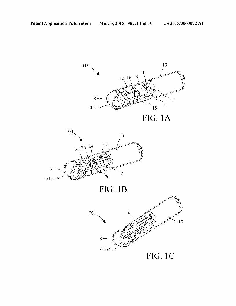
Patent Application Publication Mar 5 2015 Sheet 1 of 10 US 20150063072 Α1
100 10
100
FIG 1C
Patent Application Publication Mar 5 2015 Sheet 2 of 10 US 20150063072 Α1
8
Offset
FIG 2Α
FIG 2Β
FIG 2C
Patent Application Publication Mar 5 2015 Sheet 3 of 10 US 20150063072 Α1
FIG 3Α
Patent Application Publication Mar 5 2015 Sheet 4 of 10 US 20150063072 Α1
2
FIG
3Β
Patent Application Publication Mar 5 2015 Sheet 5 of 10 US 20150063072 Α1
FIG 5
Patent Application Publication Mar 5 2015 Sheet 6 of 10 US 20150063072 Α1
Time (ms)
FIG 6Α
υ rmdashτ -γmdash7mdashπ0 100 200 300 400 500 600
Time (ms)
FIG 6Β
Cur
rent
(mA
)C
urre
nt (m
A)
Patent Application Publication Mar 5 2015 Sheet 7 of 10 US 20150063072 Α1
005
0
^ -005o_οldquo -01
CD cn
I -015gt
-02
-02500 02 04 06 08 10
Pulse Time (s)
f(
------ SR416------ ΜΒ306
τ---------------1---------------1-------------- r
FIG 7
Patent Application Publication Mar 5 2015 Sheet 8 of 10 US 20150063072 Α1
Offset Tube SI (dB) mdashmdash Regular Tube SL (dB)
FIG 8
Patent Application Publication Mar 5 2015 Sheet 9 of 10 US 20150063072 Α1
wreflector
FIG 9
Patent Application Publication Mar 5 2015 Sheet 10 of 10 US 20150063072 Α1
FIG 10
US 20150063072 Α11
Mar 5 2015
INJECTABLE ACOUSTIC TRANSMISSION DEVICES AND PROCESS FOR MAKING AND
USING SAME
STATEMENT REGARDING RIGHTS TO INVENTION MADE UNDER
FEDERALLY-SPONSORED RESEARCH AND DEVELOPMENT
[0001] This invention was made with Government support under Contract DE-AC05-76RL01830 awarded by the US Department of Energy The Government has certain rights in the invention
FIELD OF THE INVENTION
[0002] The present invention relates generally to acoustic tracking devices and systems More particularly the present invention relates to injectable acoustic transmission devices for detection and remote tracking of host animals in up to three dimensions in real-time or as a function of time
BACKGROUND OF THE INVENTION
[0003] Acoustic telemetry involves acoustic devices (acoustic tags) commonly used to monitor the behavior of eg marine and freshwater fish Acoustic tags transmit a sound signal or acoustic ldquopingrdquo that sends identification information and location information about a tagged animal to a receiver The receiver converts sound signals into digital data Post processing software processes the digital data and provides positions of the tag in up to three dimensions (3D) when at least four receivers detect the same sound signal By determining the soundrsquos time of arrival at the hydrophone receiver the position of the tagged animal can be determined allowing tracking of the host animal Then by tying the acoustic signature received from the transmitter to the proshygrammed signal code a specific animal may be identified An array of receivers allows the movement of particular animals to be tracked[0004] Acoustic telemetry has been identified as a technolshyogy for observation of behavior and assessment of survival for juvenile Chinook salmon passing through the Federal Columbia River Power System Considerable effort has been expended to understand the biological effects of implantation of acoustic tags in yearling and sub-yearling Chinook salmon Much additional effort has gone into development of autonoshymous and cabled receiving systems that can be deployed at dams and elsewhere in rivers Receiving systems detect sigshynals emitted by the acoustic tags process the resulting detecshytion data to track the fish and provide data necessary to estimate survival through dams and other routes of passage Together the acoustic tags and receiving systems in the Columbia River system make up the Juvenile Salmon Acousshytic Telemetry System (JSATS) Although acoustic tags presshyently used for JSATS meet current tag burden guidelines for most yearling Chinook salmon the tags are too large for smaller juvenile Chinook salmon particularly those found in the lower Columbia River and estuary that enter the river downstream of Bonneville Dam Bioeffects studies also indishycate that juvenile Chinook salmon less than 95 mm in length (approximately 9 g weight) implanted with current acoustic tags have reduced survival and growth rates Accordingly new tag designs are needed that reduce the overall size weight and volume enhance the range and lifetime reduce
adverse effects associated with implantation and broaden the range of potential applications The present invention addresses these needs
SUMMARY OF THE INVENTION
[0005] The present invention includes new injectable acoustic (sound-emitting) transmission devices (injectable acoustic tags) and a process of making Injectable acoustic tags of the present invention provide identification and remote tracking of host animals including fish eg in marine or freshwater environments in up to three dimensions (3D) (ie Χ-Υ-Ζ coordinates) in real-time or as a function of time Injectable acoustic tags may be used in applications such as eg fish survival studies monitoring fish migrationpassage trajectories tracking fish behavior in two dimensions (2D) or three dimensions (3D) measuring bypass effectiveness at dams and other passages observing predatorprey dynamics helping public utility agencies private firms and state and federal agencies meet fisheries regulations and other applishycations Compared to surgically implanted (ie non-inject- able) tags injectable tags of the present invention reduce bio-handling and enhance survivability of marine animals being tracked Injectable acoustic tags of the present invenshytion transmit location identification and sensor information in an encoded acoustic signal that propagates from the tag to an external receiver The encoded acoustic signal takes the form of one or more tag codes each tag code typically but not exclusively being transmitted at regular intervals Both the tagged animal and external receiver are typically located underwater but are not limited[0006] The injectable acoustic tags incorporate new advanced features compared to conventional acoustic tags One advanced feature of the injectable acoustic tags is the ability to transmit more than one tag code This feature increases the number of unique tag identifications (IDs) that may be transmitted in the acoustic signal while maintaining full backward compatibility with existing receiver equipshyment[0007] In some applications the injectable acoustic tag may alternate transmission between two tag codes In some applications tag codes may be identical[0008] Another advanced feature of the injectable acoustic tags is that each tag code is fully configurable including eg the bit length of the code (ie code length) and the number of acoustic pulses per bit for maximum application flexibility For example in some applications a shorter tag code may be used for acoustic transmissions close to the water surface to decrease undesirable multipath effects In other applications a longer tag code may be used to permit a greater number of unique tag identifications[0009] Yet another advanced feature of the injectable acoustic tags is the ability to embed temperature or other sensor data into at least one of the tag codes and to append the correct error checking bits to the tag code based on the encoded sensor data values For example in some applicashytions temperature data collected from a temperature sensor in the injectable acoustic tag may be transmitted as part of the tag code[0010] Sensors in the injectable acoustic tag may include accelerometers rotational velocity sensors magnetometers pressure sensors temperature sensors and combinations of these various sensors[0011] Yet another advanced feature of the injectable acoustic tags is the ability to configure both the acoustic
US 20150063072 Α12
Mar 5 2015
source level and acoustic transmission frequency This feashyture allows the battery life to be optimized for the application Each injectable tag maintains the acoustic source level at approximately the same level as the battery discharges which helps ensure consistency between data collected at different times[0012] Yet another advanced feature of the injectable acoustic tags is the ability to wait for a configurable amount of time before starting normal acoustic transmissions This waitshying period can be up to 30 days or more This feature is useful for tagging marine animals prior to their migration time The injectable tags can also be placed in a state that consumes minimal power so that the tags can be stored for a year or more before use[0013] The injectable acoustic tags have a reduced size weight and volume that exceeds source level outputs and lifetimes compared with conventional acoustic tags The reduced size weight and volume of the new tags permit study of animal species with sizes that are too small for current JSATS tags which broadens the range of applications The injectable acoustic tags are also less expensive to produce and use They also provide data and information suitable for development of animal-friendly hydro systems on an internashytional scale[0014] Components of the injectable acoustic tags may be encapsulated within a capsular containment structure (capshysule) made of a thermosetting polymer (eg an epoxide thershymosetting polymer) of various defined shapes that allows the tags to be injectable Internal volumes are less than about 115 mm3 In some applications injectable acoustic tags may include a length of about 15 mm and a diameter of about 34 mm[0015] In some applications injectable acoustic tags may have a dry weight of about 220 mg or less In some applicashytions injectable acoustic tags may contain a rigid printed circuit board with various electronics components attached [0016] Injectable acoustic tags of the present invention may be powered by a single custom power source or battery that delivers a source voltage output of from about 18 V to about 30 V The battery may provide a lifetime of greater than 35 days of full-time activity at a transmission pulse rate of 5 seconds and may provide a lifetime of at least 23 days of full-time activity at a transmission rate of 3 seconds The power source may have a mass of about 75 mg or less The power source may provide an energy density of at least about 230 Whkg[0017] The power source (battery) may include a plurality of laminates configured to supply an output voltage of at least about 25 volts Each laminate may include an anode and a cathode positioned between polymer separators that electrishycally isolates the cathode from the anode in the laminate The separator may include a micro-porous polypropylene The cathode may be include or be constructed of eg carbon fluoride and a conducting carbon within a binder affixed at a selected thickness to a current collector The binder may include eg polytetrafluoroethylene (PTFE) In some applishycations the cathode may include 85 wt carbon fluoride 10 wt carbon and 5 wt polytetrafluoroethylene (PTFE) binder The current collector may include a metal mesh of aluminum or an aluminum-containing alloy The anode may include lithium metal of a selected thickness and a selected weight The cathodeanode laminates may be enclosed within a container constructed of a high mechanical strength chemishycally resistant polymer of a selected thickness The power
source may be filled with an electrolyte The electrolyte may include a selected concentration of lithium hexafluorophos- phate (LiPF6) disbursed in a selected volume ratio of ethylene carbonate (EC) and dimethyl carbonate (DMC) that minishymizes voltage drops within the power source during operashytion[0018] Injectable acoustic tags may include one or more piezoelectric transducers The number of transducers is not limited Each piezoelectric transducer may vibrate at a selected resonant frequency which transmits an acoustic sigshynal containing encoded data from the piezoelectric transducer to a receiver[0019] Injectable acoustic tags may include a controller that couples to the power source and controls various circuits and functions within the acoustic tag In some applications the controller may be a microcontroller that contains a proshycessor core memory internal oscillators timers and proshygrammable input and output peripherals which executes embedded firmware (source code) that defines its operation [0020] Injectable acoustic tags may include a resonator crystal or other type of oscillator component to provide an external clock signal to the microcontroller The microconshytroller may use an external clock signal to help control the circuits on the tag that generate the acoustic signal The microcontroller may also use an external clock signal to help calibrate its internal oscillators and timers In some applicashytions the tag uses a ceramic resonator with a resonant freshyquency of about 10 MHz with about 05 precision[0021] Injectable acoustic tags may include an infrared (IR) sensor that couples to the controller and provides an optical link to a host computer located external to the acoustic tag The infrared sensor may receive programming and configushyration information from the host computer that configures the controller for operation of the tag (eg start transmission set the transmission frequency to 3 seconds and additional operations)[0022] Injectable acoustic tags may include a boost conshyverter circuit that couples to the controller and the power source The boost converter circuit may enhance the voltages from the power source (battery) and provides those voltages to the drive circuit that drives the piezoelectric transducer The boost converter circuit may enhance the voltage from the power source that is provided to the at least one piezoelectric transducer by up to about 6 volts[0023] Injectable acoustic tags may include a drive circuit that couples to the controller and to either the boost converter circuit or the power source The drive circuit may deliver a drive voltage to the piezoelectric transducers to generate vibration in one or more vibrational modes This process in turn generates the acoustic signal that is transmitted from the injectable acoustic tags[0024] The acoustic signal transmitted from the injectable acoustic tags may contain binary (or derivative) data encoded with phase-shift keying (PSK) The binary data may contain header bits (eg a Barker code) a tag identification (ID) code data collected from one or more sensors (eg temperashyture from a temperature sensor) error checking bits (eg a cyclic redundancy check) or combinations of any or all of the above The binary data within a single acoustic signal comshyprises one tag code The injectable acoustic tag may store one or more distinct tag codes[0025] The present invention also includes a method for transmission of identification and location information about a host animal in real-time or as a function of time The method
US 20150063072 Α13
Mar 5 2015
may include injecting an injectable acoustic transmission device of a selected size and shape at a selected location in the body of the host animal Location and identification data about the host animal may be transmitted from the injectable acoustic tag located within the body of the host animal to a receiver located external to the host animal as an acoustic signal encoded with one or more tag codes of a selected code length[0026] The acoustic signal when received from the injectshyable acoustic transmission device may be decoded to identify and track the host animal in up to three dimensions in realshytime or as a function of time The method may include proshygramming the injectable acoustic tag for operation via an optical link device in the tag The programming may include configuring the injectable acoustic tag to automatically adjust the output voltage of the power source to retain a full power level as the power source discharges as a function of time [0027] Injectable acoustic tags may be injected into the body of the host animal eg along the linea alba[0028] The receiver may be an acoustic hydrophone The acoustic signal from the piezoelectric transducer may be transmitted at a source level that is programmable which results in a selectable detection range The piezoelectric transducer may be of a spherical shell geometry or tube geomshyetry The outer wall and inner wall of the piezoelectric transshyducer may be coated with an electrode that permits the piezoshyelectric transducer to be coupled to the circuit board[0029] In some applications an acoustic reflector may be coupled to the piezoelectric transducer eg behind the piezoshyelectric transducer The reflection of acoustic waves enhances the acoustic signal transmitted from the piezoelectric transshyducer The acoustic reflector may be placed in direct contact with each individual piezoelectric transducer The acoustic reflector may reflect acoustic waves emitted from the back of the piezoelectric transducer which would otherwise propashygate towards or interfere with electronic components the battery or other components of the acoustic tag to achieve desired beam patterns[0030] In some applications the acoustic reflector may be fashioned of a porous material that is filled with a gas such as air[0031] In some applications the piezoelectric transducer may be an off-centered piezoelectric ceramic tube transducer or a spherical shell transducer in which the outer circumfershyence and inner circumference of the transducers are not conshycentric The inner circumference may be offset towards the desired direction of transmission to maximize the acoustic energy emitted in that direction[0032] In some applications the piezoelectric transducer may be polarized (activated) along the wall thickness direcshytion to produce a selected vibration at a selected resonance frequency For example when actuated by an AC voltage the piezoelectric transducer may vibrate in the radial direction that resembles a breathing motion ie the so-called ldquobreathshyingrdquo vibrational mode Yet vibrational modes are not limited Length mode and thickness mode may also be used either alone or in combination with ldquobreathing moderdquo[0033] In some applications the vibrational mode may be selected to be about 10 kHz to 50 kHz higher than the freshyquency of the drive signal that drives the transducer Higher resonance frequencies can compensate for downshifts in the transducer frequency caused by the coating surrounding the transducers
[0034] Injectable acoustic tags may be programmed to transmit one or more encoded identification (ID) codes Each tag code may include a code length of up to 64 binary bits The controller may coordinate the timing and transmission of each of the tag IDs alternating transmission of eg a first tag ID and a second tag ID In some applications only a single tag code ID may be desired Format of the tag codes is selectable In some applications one of the tag IDs may be configured to transmit data from various sensors incorporated into the injectable tag[0035] The coding may include configuring the number of cycles required per bit of data transmitted from the injectable acoustic transmission device The coding may include proshygramming the injectable acoustic transmission device to transmit the one or more identification codes within the acoustic signal transmitted from the injectable acoustic transshymission device[0036] The foregoing summary is neither intended to define the invention which is measured by the claims nor to be limiting as to the scope of the invention in any way
BRIEF DESCRIPTION OF THE DRAWINGS
[0037] FIGS la-lc show different views of an embodiment of the present invention[0038] FIGS 2a-2c show different views of an offset piezoshyelectric transducer of the present invention[0039] FIG 3a is a block diagram showing electrical comshyponents of an embodiment of the present invention[0040] FIG 3b is a circuit diagram of one embodiment of the present invention[0041] FIG 4 is a cross-sectional view of a power source of the present invention[0042] FIG 5 compares resistances for a power source of the present invention against a conventional power source at temperatures ranging from -5deg C to 25deg C[0043] FIGS 6a-6b compare the transmitter pulse current for the power source of the present invention against a conshyventional power source at 25deg C and 0deg C respectively [0044] FIG 7 compares the voltage drop for the power source of the present invention against a conventional power source during a pulse transmission at 0deg C[0045] FIG 8 compares beam patterns for an offset (ηοη- concentric) piezoelectric transducer of the present invention against a conventional (concentric) piezoelectric transducer [0046] FIG 9 compares beam patterns of injectable tags of the present invention that include various spacing widths positioned behind the piezoelectric transducers[0047] FIG 10 shows a top and a bottom portion of an injection mold for encapsulation of injectable tags of the present invention
DETAILED DESCRIPTION
[0048] New injectable acoustic transmission devices (inshyjectable acoustic tags) and a process of making are detailed that provide identification and remote tracking of marine or freshwater animals including fish in water environments in up to three dimensions (3D) (ie Χ-Υ-Ζ coordinates) in realshytime or as a function of time Features of the injectable acousshytic tags can be tailored for various unique applications and projects Studies may be conducted in lakes rivers tributarshyies estuaries and at sea The following description includes a best mode of the present invention While the present invenshytion is susceptible of various modifications and alternative
US 20150063072 Α14
Mar 5 2015
constructions it should be understood that there is no intenshytion to limit the present invention to specific forms disclosed herein but on the contrary the present invention is to cover all modifications alternative constructions and equivalents falling within the scope of the present invention as defined in the claims Therefore the present description should be seen as illustrative and not limiting Additional features of the present invention are detailed by Deng et al in a document entitled ldquoJSATS Injectable Acoustic Transmitter Reference Design Documentationrdquo prepared by the Pacific Northwest National Laboratory (Document No PNNL-22372) for the US Army Corps of Engineers Portland District March 2013 which reference is incorporated herein in its entirety [0049] FIG la illustrates a top view of an injectable acousshytic (sound-emitting) transmitter device (tag) 100 in assembled form showing exemplary components While varishyous components are described herein components and conshyfiguration are exemplary and not limited For example in various embodiments injectable acoustic tags of the present invention may include various form factors and shapes that allow the tags to be injectable and tailored for selected applishycations ldquoForm factorrdquo refers to the physical arrangement configuration and dimensions of components in the injectshyable acoustic tags including but not limited to eg circuit boards piezoelectric transducers controllers acoustic reflecshytors inductors capacitors diodes and capsules In some embodiments injectable tag 100 may have a generally elonshygated or cylindrical shape that permits the tag to be injectable into the host animal but shapes are not intended to be limited Components of tag 100 may be encapsulated within a coating that defines a capsule 4 Capsule 4 may be composed of a thermosetting polymer such as an epoxy (eg EPO-TEKreg 301 epoxy Epoxy Technology Inc Billerica Mass USA) or a resin (eg Electrical Resin 53Μ Company St Paul Minn USA) Capsule 4 may include an exemplary length of about 15 mm but length is not limited Diameter of capsule 4 at the widest point along the length may be about 34 mm Final weight may be at or below about 228 mg[0050] In various embodiments selected components of tag 100 may be mounted onto a circuit board 2 constructed of suitable or selected circuit board materials available commershycially (eg Sierra Circuits Inc Sunnyvale Calif USA) Circuit board 2 materials may include but are not limited to eg a rigid material such as FR4 board with a thickness of about 0008 or flexible materials such as flex board with a thickness of about 0003 In various embodiments circuit boards 2 of tag 100 may be configured with both a top side and a bottom side each side of circuit board 2 configured with selected electrical circuits andor device components Circuit board 2 may include exemplary spacing widths and copper line widths for electrical circuits of about 0003 but are not limited As will be appreciated by those of ordinary skill in the art circuit configurations and associated designs and tag components may be altered without departing from the spirit and scope of the present invention Thus no limitations are intended[0051] Injectable tag 100 may include a controller 6 that controls operation of components and circuits of the tag A piezoelectric transducer 8 may be positioned at a forward end of the tag so that the acoustic signal may be transmitted from the tag without encountering interference from tag composhynents such as an inductor 12 or other components of the tag In the figure piezoelectric transducer 8 is shown electrically coupled to circuit board 2 but does not need to reside on
circuit board 2 A power source 10 may be coupled to circuit board 2 to power components of the injectable tag In some embodiments power source 10 may be positioned at an end opposite to piezoelectric transducer 8 to minimize any potenshytial blockage of the acoustic signal caused by the physical size of the power source 10 Flowever location is not limited A capacitor 14 (eg a 1 pF capacitor) may act as a decoupling capacitor for the power source to help smooth any electrical noise A first MOSFET transistor 16 may form part of a boost converter circuit described further herein A second MOSshyFET transistor 18 and an inductor 12 (eg a 100 μΕ1 inductor) may form a drive circuit described further herein A phoshytotransistor 20 sensitive to infrared radiation may provide an optical link to an external programmer module (FIG 3b) for receipt of commands that configure microcontroller 6 for operation[0052] FIG lb illustrates a bottom view of injectable acoustic transmission tag 100 showing exemplary composhynents on a bottom side of circuit board 2 A capacitor 22 (eg a 22 pF capacitor) an inductor 26 (eg a 47 μ1Τ inductor) and a diode 30 (eg a Schottky diode) together form part of a boost converter circuit described further herein A resonator 24 (eg a 10 MFlz ceramic resonator) may couple to the microcontroller (FIG la) to produce a clock signal for conshytrolling the operation of that microcontroller A resistor 28 (eg a 1 ΜΩ resistor) may couple to the resonator to help stabilize the clock signal[0053] FIG lc shows an injectable acoustic transmission tag 200 of a ldquobaseball batrdquo capsule design In the instant embodiment components of the tag are encapsulated in a capsule 4 that has an appearance of a baseball bat with a narrowed front end (the ldquohandlerdquo of the ldquobatrdquo) and a power source 10 positioned at a back end of the capsule (the ldquohitting endrdquo of the ldquobatrdquo) The narrowed front end reduces the weight and volume of injectable acoustic transmission tag 200 Capshysule 4 may have an exemplary length of about 15 mm but is not limited Diameter of tag 200 at the widest point along the length of the capsule (ie at the location of the power source 10) is about 34 mm Average weight may be between about 216 mg and about 218 mg when EPO-TEK 301 epoxy or 3Μ Electrical Resin 5 is used as the coating material[0054] FIG 2a shows a top view of a piezoelectric tube transducer 8 of an offset inner circumference (IC) design Piezoelectric transducer 8 converts electrical energy from the power source (FIGS la-lc) into ultrasonic energy (ie an acoustic signal) that is transmitted to a receiver (not shown) Piezoelectric transducers 8 may be constructed of any suitshyable piezoelectric ceramic material including eg lead zir- conate titanate (ΡΖΤ) lead magnesium niobate-lead titanate (ΡΜΝ-ΡΤ) or lead-free ceramic materials such as sodium potassium niobate (ΚΝΝ) and bismuth sodium titanate (ΝΒΤ) IC-offset piezoelectric transducer 8 may include an inner wall 32 and an exterior (outer) wall 34 that are not concentric The circumference of inner wall 32 may be offset from the center position of exterior wall 34 When assembled into the injectable tag the IC-offset piezoelectric transducer 8 may be oriented with the thinnest portion of the transducer wall facing the front of the tag The offset maximizes energy delivered from the piezoelectric transducer in the direction of the offset Dimensions of piezoelectric transducer 8 may be tailored to provide a selected operation frequency Frequenshycies are not limited In some embodiments the resonance frequency is selected to be about 4167 kHz In the instant embodiments IC-offset piezoelectric transducer 8 may
US 20150063072 Α15
Mar 5 2015
include an exterior (outer) wall 34 with an OD of about 24 mm to about 26 mm an inner wall 32 with an ID of about 17 mm to about 19 mm and a thickness in the offset direction of about 015 mm Dimensions of piezoelectric transducer 8 may include a tolerance at least about plusmn005 mm In some embodiments piezoelectric transducer 8 may have a resoshynance frequency about 10 kHz to 50 kHz higher than the frequency of the drive signal that drives piezoelectric transshyducer 8 The higher frequency compensates for frequency downshifts that may be caused by the epoxy or resin coating on the piezoelectric transducer
[0055] FIG 2b is a schematic showing the acoustic transshymission device 100 in assembled form configured with an inner circumference (IC)-offset piezoelectric transducer 8 positioned at a front end of the device a power source (batshytery) 10 at a back end of the device and a circuit board 2 in the middle section IC-offset piezoelectric transducer 8 may include an inner wall 32 with an inner circumference (IC) and an exterior (outer) wall 34 that are offset in the forward transmission direction The offset may enhance the source level of the acoustic signal when the piezoelectric transducer is polarized (activated) along the thickness direction Piezoshyelectric transducer 8 may include a closed-cell foam 9 comshyposed of eg EPDM rubber ora like elastomer positioned so as to be bounded by inner wall 32 of piezoelectric transducer 8 that enhances acoustic properties of piezoelectric transshyducer 8 Dimensions of IC-offset piezoelectric transducer 8 are selected that maximize the transmission range of the acoustic signal IC-offset piezoelectric transducer 8 is prefshyerably oriented so that the direction of the IC-offset is directly pointed towards a receiver (hydrophone) (not shown) that detects the acoustic signal emitted by the piezoelectric transshyducer 8 but is not limited
[0056] FIG 2c shows a schematic of an injectable acoustic transmission device 200 of a baseball bat design In the figure piezoelectric transducer 8 may include an inner wall 32 and an exterior (outer) wall 34 that are concentric or that are offset as detailed previously herein Injectable tag 200 may also include an acoustic reflector 36 attached behind piezoelectric transducer 8 in front of power source (battery) 10 and circuit board 2 Acoustic reflector 36 reflects acoustic signals emitted from piezoelectric transducer 8 and enhances transmission in the forward direction from the acoustic (tag) 200 as detailed further herein In some embodiments acoustic reflector 36 may include or be composed of an ultra-low density material such as EPDM closed-cell (-03 mm thick) foam which may be attached to the back surface of piezoelectric transducer 8 in front of circuit board 2 The foam introduces an interface with a laige acoustic impedance mismatch greater than about 20x10s kg(m2-s) that redirects acoustic energy towards the front end of injectable tag 200 In addition acoustic reflector 36 enhances the source level of the acoustic energy output from piezoelectric transducer 8 along the forward 180 degree wavefront by at least a factor of about 05 dB to about 1 dB on average but acoustic eneigy values are not intended to be limited In various embodiments acoustic reflector 36 may include various selected thicknesses In some embodiments width of acoustic reflector 36 may be below about 15 mm to avoid blocking acoustic signals emitted from the two (ie left and right) sides of piezoelectric transducer 8 Thickness of acoustic reflector 36 depends in part on the size of the pores within the closed-cell foam Thickness is preferably 2 to 3 times the size of pores within the reflector material to ensure
acoustic waves encounter EPDMair interfaces within the reflector foam at least once in order to maximize effectiveness of the reflector[0057] Piezoelectric transducer 8 may include a closed-cell foam 9 composed of eg EPDM rubber or a like elastomer positioned so as to be bounded by inner wall 32 of piezoelecshytric transducer 8 that enhances acoustic properties of piezoshyelectric transducer 8 In some embodiments piezoelectric transducer 8 may include end caps 38 of a selected thickness (eg -02 mm) positioned at respective flat ends of transshyducer 8 End caps 38 may include or be composed of a selected metal such as copper (Cu) metal End caps 38 may be bonded to piezoelectric transducer 8 using eg a non-con- ductive epoxy End caps 38 can serve to enhance the source level of the acoustic signal emitted from flat ends of transshyducer 8[0058] FIG 3α is a block diagram showing various composhynents of injectable acoustic tags of the present invention Tags may include a controller component 6 (eg a 6-pin microshycontroller) The term ldquomicrocontrollerrdquo does not imply or limit selected dimensions for this component A ceramic resoshynator 24 may be coupled to microcontroller 6 and used to generate a clock signal for coordinating operation of various circuits An infrared sensor 20 may provide an optical link that receives and delivers configuration commands from an external infrared programmer module (FIG 3b) to controller 6 Configuration commands may specify various parameters for the operation of the microcontroller including but not limited to eg tag codes period between transmissions and other operation parameters A boost converter circuit 40 enhances voltages from power source 10 and delivers the enhanced voltages to a drive circuit 42 Drive circuit 42 drives piezoelectric transducer 8 to transmit an encoded acoustic signal at a specified frequency as detailed further herein [0059] FIG 3b shows an exemplary block diagram illusshytrating circuits and associated device components for injectshyable acoustic tags of the present invention Components described hereafter provide reduced physical dimensions and weights to the tag and allow circuits to operate at comparashytively high efficiencies given their smaller sizes However components are not intended to be limited All components as will be selected by those of ordinary skill in the art in view of the description are within the scope of the present invention No limitations are intended[0060] Injectable acoustic transmission devices (tags) of the present invention may include a controller (Ul) 6 (eg a model PIC16F1823TCL 8-bit 8Κ flash programmable microcontroller in a chip-scale package Microchip Techshynologies Chandler Ariz USA) with a low current draw (eg 20 ηΑ in sleep mode or 300 ηΑ in sleep mode with the watchdog timer active) Controller 6 is a programmable comshyponent that controls operation of circuits and electrical comshyponents within injectable acoustic tag 100 Controller 6 may operate from input voltages between about 18 V and about 36 V Selected voltages are compatible with a power source (battery) 10 Controller 6 may include modules or composhynents such as eg an internal oscillator sleep mode inter- rupt-on-change capability a fixed voltage reference a temshyperature sensor timers pulse width modulators and a Universal Asynchronous ReceiverTransmitter (UART) Controller 6 generates control signals for both a boost conshyverter circuit 40 and a drive circuit 42[0061] Power source (battery) 10 may be connected to tershyminals (J4) 46 and (J5) 48 on either each side of circuit board
US 20150063072 Α16
Mar 5 2015
2 during assembly Piezoelectric transducer 8 may be conshynected to terminals (J3) 50 and (Jl) 52 on opposite sides of circuit board 2 at an end opposite power source 10 A bypass (or decoupling) capacitor (C2) 14 (eg a model AMK063ABJ105MP-F 1-pF 4V X5R 20 0201 tantalum capacitor Taiyo Yuden Co Ltd Schaumburg 111 USA) may be used to help filter any electronics noise on power source 10 and reduces maximum peak currents drawn from power source 10 when controller 6 or boost converter circuit 40 draws current
[0062] A resonator (Yl) 24 (eg a modelCSTCE10M0G52-R0 100 MHz SMD ceramic resonator Murata Manufacturing Co Ltd Nagaokakyo Kyoto Prefecshyture Japan) may be coupled on the input side of controller 6 to generate a precise clock signal with a selected precision (eg plusmn05 precision) Controller 6 may use the clock signal to generate control signals for boost converter circuit 40 and drive circuit 42 Due to the 10 MHz rating of resonator (Yl) 24 control signals for drive circuit 42 permit the circuit to generate an acoustic signal at desired modulation frequenshycies eg 4167 kHz Control signals generated by controller 6 can be synchronized to 4167 kHz when controller 6 uses the clock signal as its input timing source The clock signal controls and modulates the (modulation) frequency of piezoshyelectric transducer 8 A resistor (Rl) 28 (eg a model CRCW02011M00FKED 10 ΜΩ V20 W 5 0201 SMD resistor Vishay Intertechnology Inc Malvern Pa USA) may be placed in parallel with resonator 24 to reduce startup time and improve stability of the generated clock signal
[0063] A unidirectional infrared sensor or phototransistor (Ql) 20 (eg model ΡΤ19-21Β Flat Black Mini (3-mm) SMD Phototransistor Everlight Electronics Co Ltd Taipei Taishywan) may couple to controller 6 using an input pin such as a UART pin (not shown) configured with ldquointerrupt-on- changerdquo capability that produces an interrupt upon a positive andor negative change in logic level Pin selections are not limited
[0064] Phototransistor 20 is sensitive to infrared light and provides an optical link that may be used to interface the inj ectable tags to an external infrared Integrated Circuit Serial Programmer (ICSP) module (Programmer) 56 (eg a MPLABICD 3 programmer Microchip Technologies Chanshydler Ariz USA) Programmer module 56 may load configushyration and programming information including firmware code into controller 6 Programmer 56 may connect to an RS-232 serial port (not shown) of a host computer (not shown) The external infrared programmer module may include an infrared LED (not shown) that indicates when the programmer is ldquoonrdquo or ldquooffrsquo For example the LED is ldquoonrdquo when the transmit line is logic 0 (positive voltage) and ldquooffrsquo when the transmit line is logic 1 (negative voltage) Writing bytes to the serial port of the host computer transmits those bytes across the infrared link 20 (ie from the infrared LED to phototransistor 20) into the tag controller 6 The infrared link 20 provides no direct feedback to the host computer
[0065] Phototransistor 20 when activated by infrared light receives configuration commands through the optical link and transfers the commands to controller 6 Delivery of conshyfiguration commands into controller 6 configures various parameters of the tag including eg tag codes transmission period and other parameters for operation prior to or followshying injection of the tag into the host animal The infrared link
is reliable simple requires a minimum number of composhynents and avoids false triggering problems after injection of the tag into the host animal[0066] Data transmission protocol over infrared link 20 may consist of a 2-second serial break followed by a stream of bytes The serial break turns on the infrared LED on infrared programmer module 56 for an extended period of time so that microcontroller 6 may sense the infrared light and prepare to configure parameters The stream of bytes may consist of an initial check byte a byte that indicates the total number of data bytes in the transmission and the selected data bytes Data bytes may specify values for the internal microcontroller parameters in a predefined order The host computer may run an exemplary MATLAB (MathWorks Inc Natick Mass USA) software program that delivers configuration informashytion through a serial port into the infrared programmer While MATLAB is described other computer programming lanshyguages may be used No limitations are intended[0067] In some embodiments phototransistor 20 provides atransferrateofabout300baud However parameter transfer rates are not intended to be limited Phototransistor 20 genshyerally operates as a simple pull-down transistor triggered by infrared light Controller 6 may activate a weak internal pull- up resistor to generate a logic high input on the input pin (eg a UART pin) when phototransistor 20 is not activated Conshytroller 6 may disable phototransistor 20 to save power by driving the input pin to ground[0068] Boost converter circuit 40 enhances voltages output from power source (battery) 10 into higher voltages Drive circuit 42 may use these higher voltages to drive piezoelectric transducer 8 Boost converter circuit 40 may include an inductor (LI) 12 (eg a model GLFR1608T470M-LR 47 μΗ 35 mA 20 0603 inductor TDK Corp New York ΝΥ USA) that stores magnetic energy as an electronic current a MOSFET transistor (Q2) 16 (eg a model PMZ390UN N-channel type 30V 178 A SOT-883 MOSFET Fairchild Semiconductor San Jose Calif USA) that switches on and off repeatedly a diode (Dl) 30 (eg a model SDM02U30LP3 30V diode Diodes Incorporated Plano Tex USA) that conducts current primarily in one direction toward the output and a capacitor (Cl) 22 (eg a model 298D226X0010Μ2Τ 22-pF 10V 20 0603 tantalum capacitor Vishay Sprague Malvern Pa USA) that stores an elevated voltage MOSFET transistor (Q2) 16 is coupled to the output of controller 6[0069] When transistor (Q2) 16 is switched ldquoonrdquo by conshytroller 6 current begins to increase in inductor (L2) 26 When transistor (Q2) 16 is switched back ldquooffrsquo by microcontroller 6 current from inductor (LI) 12 is delivered through diode (Dl) 30 into capacitor (Cl) 22 which charges capacitor (Cl) 22 Controller 6 may switch transistor (Q2) 16 ldquoonrdquo and ldquooffrsquo a selected number of times to charge capacitor (Cl) 22 to a desired value Capacitor (C1) 22 may have a minimum rating of about 10 V and a capacitance of at least about 22 pF to minimize voltage drops while drive circuit 42 is drawing current Boost converter circuit 40 delivers a suitable drive voltage (HVDD) 58 as an input to drive circuit 42[0070] A drive circuit 42 may be coupled on the output side of microcontroller 6 to facilitate transmission of the acoustic signal from piezoelectric transducer 8 Drive circuit 42 may define the signaling levels and signaling approach of the injectable tag Drive circuit 42 may include an inductor (L2) 26 (eg a model BRL2012T101M 100 μΗ 85 mA 20 SMD Inductor Taiyo Yuden Co Ltd Schaumburg 111 USA) that
US 20150063072 Α17
Mar 5 2015
stores magnetic energy as an electronic current and a MOS- FET transistor (Q3) 18 (eg a model PMZ390UN N-channel type 30V 178 A SOT-883 MOSFET Fairchild Semiconducshytor San Jose Calif USA) that switches on and off Transistor (Q3) 18 maybe coupled to an output pin of controller 6 Drive circuit 42 may attach to terminals (J1) 50 and (J3) 52 of circuit board 2 Voltage at connector 52 is tied to elevated voltage (HVDD) 58[0071] When transistor (Q3) 18 is switched ldquoonrdquo by microshycontroller 6 current begins to increase in inductor (L2) 26 Voltage at connector 52 may be set to ground When transistor (Q3) 18 is then switched ldquooffrsquo by microcontroller 6 inductor (L2) 26 and piezoelectric transducer 8 conceptually form a resonant LC circuit Voltage at connector 52 of piezoelectric transducer 8 may oscillate at a frequency determined by the inductance of inductor (L2) 26 and the characteristic capacishytance of piezoelectric transducer 8 Oscillation frequency may be greater than the desired modulation frequency of the acoustic signal Voltage on connector 52 may increase above drive voltage (F1VDD) 58 and then return to near ground Transistor (Q3) 18 may be switched back ldquoonrdquo by microconshytroller 6 to prevent further oscillations from taking place in piezoelectric transducer 8 Voltage differences across piezoshyelectric transducer 8 connected between terminal 50 and tershyminal 52 may thus range between negative and positive valshyues[0072] Controller 6 may switch transistor (Q3) 18 ldquoonrdquo and ldquooffrsquo in a particular pattern so that drive circuit 42 can apply the desired electrical signals to the piezoelectric transducer and generate the correct acoustic waveform To transmit a series of acoustic pulses representing one bit of the tag code microcontroller 6 may apply a square wave to transistor (Q3) 18 with the desired modulation frequency (eg 4167 kFlz) The duty cycle of the square wave is typically 33 so that transistor (Q3) 18 is switched ldquoonrdquo for one-third of each modulation period and inductor (L2) 26 and piezoelectric transducer 8 are allowed to oscillate for two-thirds of each modulation period When transitioning from a logic ldquo0rdquo bit to a logic ldquo1rdquo bit or vice versa microcontroller 6 may delay a next pulse by a time period that is one-half of a modulation period This procedure produces an acoustic signal from piezoelectric transducer 8 that includes encoded binary data implemented eg by way of phase-shift keying (PSK) [0073] In various embodiments separate MOSFET transisshytors (Q2) 16 and (Q3) 18 may be used rather than a single dual-channel MOSFET transistor to facilitate layout and design on circuit board 2 but is not intended to limited thereto Further components on circuit board 2 described herein may be placed in close proximity to minimize length of the tags For example resonator 24 and inductor (L2) 26 may be in contact after board assembly without problems since resonator 24 has a perimeter surrounded by a nonconductive material[0074] FIG 4 shows a cross-sectional view of the custom power source (battery) 10 (termed ΜΒ306 hereafter) that supplies power to acoustic transmitter (tag) (FIGS la-lc) and electrical components of the present invention Battery 10 may include a cathode 62 that includes a composite of carbon monofluoride as an active cathode material mixed with a conductive carbon in a binder such as polytetrafluoroethylene (PTFE) to form a free-standing electrode In an exemplary embodiment composite cathode 62 may include 85 wt active cathode material 10 wt conductive carbon (eg SUPER-Preg conductive carbon Timcal Ltd Bodio Switzershy
land) and 5 wt PTFE The composite cathode material when dried may be introduced (eg pressed) onto a current collector support 64 constructed of aluminum (or other metal) mesh to form the composite cathode electrode 62 Current collector 64 provides electron transfer between respective cathode 62 and anode 72 electrodes in battery 10 A metal lead 66 [eg positive (+) lead] constructed eg of enameled copper wire (eg 013 mm OD)] which may be soldered to current collector 64 Composite cathode 62 (with or without a copper wire lead 66) may be divided into sections with selected dimensions Individual cathode sections 62 may be introduced between two layers of a separator 70 material composed eg of a micro-porous polypropylene (eg Sepashyrator 2500 Celgard LLC Charlotte NC USA) that electrishycally isolates cathode 62 from anode 72 in individual cathode anode laminates (couples) 74 Anode 72 may include or be composed of lithium metal [FMC lithium Charlotte NC USA] with selected thicknesses In some embodiments thickness of the anode 72 may be about 015 mm but is not limited An anode lead 68 (eg 013 mm OD) may be constructed of eg copper and coupled to anode 72 by directly pressing lead 68 onto the lithium metal[0075] Multiple individual electrochemical cathodeanode couples (laminates) 74 each comprising a cathode 62 and an anode 72 may be bundled together and introduced into a container 76 In various embodiments laminates 74 may include a thickness between about 021 mm and about 024 mm but dimensions are not intended to be limited Container 76 may be of a generally cylindrical shape and constructed of a high strength material such as a fluoropolymer eg ethylshyene tetrafluorethylene (ETFE) sold commercially under the tradename TEFZELreg (DuPont Wilmington Del USA) or aluminum The polymer includes a high melting temperature a high flow rate and excellent chemical and electrical resisshytance properties With laminates 74 introduced into container 76 container 76 may be filled with an electrolyte 78 (up to 35 mg on average) to minimize time delays characteristic of conventional CF electrochemical cells In various embodishyments electrolyte 78 may include or be composed of eg 1Μ lithium hexafluorophosphate (LiPF6) that is disbursed in a 11 volume ratio [ECDMC] of ethylene carbonate (EC) in dimethyl carbonate (DMC) Container 76 may then be capped with a polymer lid 80 after inserting wire leads 66 and 68 through holes (not shown) introduced in lid 80 Battery 10 when assembled may be sealed eg with an epoxy or other thermosetting polymer TABLE 1 shows physical properties of the battery of the present invention compared against conshyventional (SR416) silver oxide (Qty=2 stacked) batteries
TABLE 1
lists typical physical properties of the ΜΒ306 battery compared with conventional silver oxide batteries
BatteryDiameter Length Volume
PackageContainer
Weight(mg)
WallThickness
TotalWeight
(mg)ΜΒ306 30 60 42 17 015 75SR416 48 32 58 na na 260(Qty 2)
[0076] As shown in the table battery 10 may have an outer diameter of 30 mm and a length of 60 mm (tolerance plusmn02 mm) Thickness of the wall of battery 10 capsule wall and lid
US 20150063072 Α18
Mar 5 2015
is about 015 mm but is not limited The battery has a low mass [approximately 0075 g (plusmn002 g)] and a low volume [approximately 0042 cm3] Current weight of the battery represents -71 reduction in the weight burden for tagged animals compared with prior art designs TABLE 2 compares performance properties of the ΜΒ306 battery against comshymercial silver oxide batteries
TABLE 2
lists typical operating and performance parameters of the ΜΒ306 battery
Impedance((a) 1 kHz) Total
Open Circuit Voltage (OCV) ocv
ccv(43 kQ
lead)
Capacity(Cut-off15V) Enersv Density
(Volts) (Ω) (Ω) (mAh) Whkg WhL
285-325 le200 6-10 ~73 231 408
[0077] Battery 10 may include a discharge rate of about 86 mAg (1 mAcm2) at 23deg C Cut-off voltage may be about 15 V Battery 10 may also deliver a gravimetric energy density of 231 Whkg (volume energy density of 408 WhL) an enhancement of greater than 133 over conventional SR416 batteries In operation battery 10 may also deliver a stable output voltage of at least 285 volts and stable pulse current over a wide temperature range from 0deg C to 25deg C This output voltage is nearly 1 V higher than commercial 416 batteries which removes the need to stack batteries as in prior JSATS transmitters or the need for extra electronics to achieve a 3 V output Battery 10 may also have an intrinsically lower impedance compared with SR416 cells used in prior art JSATS transmitters FIG 5 compares the impedance of the battery of the present invention against conventional SR416 cells Data show the performance of the battery of the present invention is superior to SR416 cells over a wide temperature range from-5deg C to 25deg C and beyond Additional aspects of the power source are detailed by Chen et al in a publication entitled ldquoMicro-Battery Development for Juvenile Salmon Acoustic Telemetry System Applicationsrdquo which reference is incorporated herein in its entirety[0078] Battery 10 may provide a long service lifetime and steady voltage performance forthe active transmission device compared to conventional transmitters known in the art that employ dual SR416 cells Lifetimes of the power source 10 are selectable based on the selection of pulse rate (current) intervals (PRIs) Pulse currents are not limited In some embodiments for example the battery may be configured to deliver a pulse current (PRI) every 3 seconds providing an active lifetime rating of at least 20 days In some embodishyments the battery may be configured to deliver a pulse current (PRI) every 5 seconds providing an active lifetime rating of
at least 30 days Longer lifetimes may be selected 7 seconds 40 days and 10 seconds 60 days No limitations are intended [0079] FIG 6a compares pulse currents (mA) generated by the ΜΒ306 battery of the injectable tags at 25deg C and 0deg C FIG 6b compares pulse currents generated by conventional silver oxide batteries at 25deg C and 0deg C Results show amplishytudes of pulse currents of the ΜΒ306 battery are both greater and delivered more rapidly than those obtained with silver oxide cells[0080] FIG 7 compares cell voltages for the ΜΒ306 batshytery upon a pulse transmission at 0deg C against conventional SR416 silver oxide cells Data show that voltage drops forthe SR 416 cells are about a factor of two greater at low temperashytures compared with the ΜΒ306 battery When in an inactishyvated state the injectable acoustic tag of the present invention maintains a battery capacity of greater than 85 for 12 months after assembly when stored at room temperature (23deg C)
Controller Firmware[0081] Source code loaded into the controller (FIG 3a) memory may be used to control the functionality and operashytion of the injectable acoustic tag Source code may be proshygrammed (eg using the MPLAB integrated development environment or like software tools) on a host computer in assembly language (eg PIC assembly language) or a higher level language (eg C programming language) The software tools on the host computer create the firmware eg in binary or derivative code (eg hexadecimal or hex) that can be programmed into the controller on the circuit board (FIG 1) Source code may be divided into various exemplary modules including but not limited to main specifies configuration bits declares variables and executes initial instructions after the controller is reset initialize clears all working variables calibrate calibrates timers (eg the watchdog timer) used to set the transmission frequency waiting periodically checks the infrared sensor until the tag is configured storage keeps the infrared sensor active until the tag is configured hibershynate waits for a specified amount of time (eg 30 days) before starting acoustic transmission running waits for a specified period (eg 3 seconds) between acoustic transmisshysions transmit activates the boost converter circuit (FIG 3a) and the drive circuit (FIG 3a) to generate the desired acoustic signal on the piezoelectric transducer (FIG 1) program reads configuration data from the infrared link and sets the operating mode and other parameters debug contains code for development purposes and tables contains lookup tables for performing arithmetic operations required to compute temperatures or other sensor data Controller firmware may contain one or more parameters that control the functionality and operation of the tag These parameters may be initialized to default values when the microcontroller powers up for the first time and later configured to new values via the infrared link TABLE 3 lists exemplary parameters that may be stored in the controller memory to control operation of the injectable acoustic transmission devices (tags)
TABLE 3
lists exemplary parameters in controller memory with associated memory requirements for operation of injectable acoustic transmission devices (tags)
NAME BYTES DESCRIPTION
NextState 1 Specifies the operating mode of the controller The state containsa series of bits whose functions are explained in the source code Common values are as follows04 hex place controller in waiting mode 08 hex place controller in storage mode
US 20150063072 Α19
Mar 5 2015
TABLE 3-continued
lists exemplary parameters in controller memory with associated memory requirements for operation of injectable acoustic transmission devices (tags)
NAME BYTES DESCRIPTION
Runlnterval 2
11 hex calibrate then hibernate then transmit21 hex calibrate then transmitPulse rate interval in units of 65536 ms The least significant byte
HibeTotal 2
is first For short pulse rate intervals the value may be decreased to compensate for delays in the controllerHibernate duration in units of 19089 hr The least significant byte
ChrgTable 6is firstA table of charge durations vs battery voltage in units of 2048 ps
Cal Interval 2
A first value specifies charge duration of the boost converter for a lowest range of battery voltages A second value may specify charge duration for a second lowest range of battery voltages etc Higher values result in a higher source level but also increase energy consumption The relationship may be characterized empiricallyNumber of transmissions between calibrations Controller may
XmitCycles 1
calibrate timers to ensure that pulse rate interval remains accurate The same parameter value may be used in hibernate mode to specify number of 256-second intervals between calibrations The least significant byte may be firstCycles per bit minus two The value should be 8 for backward
Xmitlnsert 1compatibilityIndex to insert temperature and CRC (check code) in tag code Β
XmitState 1
or ldquo0rdquo if no insertion is performed Temperature may use 5 bits and CRC may use 8 bitsParameter may be ldquo0rdquo when changing XmitCode values
XmitCode 64 Table of transmit codes Each value specifies one bit of tag code
CRC Table 32
A and one bit of tag code Β as listed below where bit 0 is theleast significant bitbit 0 transmit bit for code Abit 1 contains 1 at the last bit position for code Abit 4 transmit bit for code Βbit 5 contains 1 at the last bit position for code ΒTable of CRC codes that correspond to various temperatures
Sensor Data
[0082] Controller (FIG 3a) may contain an internal temshyperature sensor The controller may embed a 5-bit temperashyture value (or other sensor value of possibly different length) within one or more tag codes that are transmitted by the piezoelectric transducer to the receiver Due to the manner in which the controller compensates for variations in the battery voltage the temperature sensor output may output a numeric value from 0 to 31 that varies with temperature but is not an actual temperature in degrees Celsius Calibration for each tag may be performed off-board to determine the relationship between numeric values and actual temperatures eg by recording numeric values at several different temperatures Controller source code may perform the required on-board arithmetic to remove effects of the battery voltage on the temperature data This procedure may be run eg from the running module described previously herein To enhance pershyformance the source code may implement several arithmetic operations as table lookups but is not limited thereto No limitations are intended
Transmission Detection Range
[0083] Acoustic signals transmitted by tags of the present invention may include a detection range of up to about 1 km (3280 ft) in fresh water Flowever no limitations are intended For example in locations with a relatively large amount of background noise such as immediately downshystream of a dam spillway signals may be transmitted about 100 meters In other locations with a relatively small amount
of background noise such as the middle of a lake signals may be transmitted up to about 500 meters Flowever distances are not intended to be limited Tag signals can be encoded for maximum strength to improve range and resolution
Beam Transmission Patterns
[0084] FIG 8 compares beam patterns for an IC-offset (non-concentric) piezoelectric tube transducer (eg a model610FlD ΡΖΤ tube transducer TRS Technologies Inc State College Pa USA) used in concert with the present invention against a conventional (concentric) piezoelectric transducer In the test configuration the inner circumference of the IC-offset piezoelectric tube transducer was offset from the tube center by 015 mm Results show acoustic energy (source level output) delivered to the front 180deg (ie from 0deg to 90deg and from 270deg to 0deg) of the injectable tag is enhanced Acoustic eneigy (source level output) delivered from the front of the piezoelectric tube transducer provides a beam pattern that is preferably omnidirectional at least over the front 180deg of the wavefront Acoustic energy delivered to the rear 180deg (ie from 90deg to 270deg) is reduced The IC-offset can be tailored to enhance the acoustic signal emitted towards the front of the tag up to the mechanical limits of the piezoelectric material[0085] Beam pattern may also be affected by the shape of the epoxy coating on the piezoelectric transducer dimensions of electronic components positioned behind the piezoelectric transducer and the gap or spacing behind or between the piezoelectric transducer and other electronic components
US 20150063072 Α110
Mar 5 2015
Tests show that electronic components positioned behind the piezoelectric transducer with a height dimension greater than 1 mm can generate a beam pattern with acoustic outputs that are lower on two or more sides of the tag Thus to achieve an omnidirectional beam pattern the epoxy coating on the tube piezoelectric transducer should be thin (lt02 mm) The coatshying should also conform to the outer surface of piezoelectric transducer to minimize irregularities in the coating which can cause fluctuations in the source level leading to non-uniform beam patterns Wavefront effects stemming from interactions between emitted and reflected acoustic waves can be minishymized by inserting a reflector behind the piezoelectric transshyducer as described herein[0086] FIG 9 shows exemplary beam patterns for injectshyable acoustic tags of the present invention A separation gap 54 positioned directly behind the piezoelectric transducer and a (eg 16 mm tall) inductor (FIG la) may include various selected width or spacing dimensions (eg 023 mm and 057 mm) In some embodiments the tag may be equipped with an acoustic reflector 36 composed of eg EPDM closed-cell foam which may be placed within gap 54 to improve the beam pattern of the tag In exemplary embodiments tags equipped with an acoustic reflector 36 placed within the gap 54 show a beam pattern with a 180deg wavefront (ie from 0deg to 90deg and from 270deg to) 0deg that becomes more uniform as the gap spacing between the piezoelectric transducer and inductor 12 (or another component) increases Results may be attributed to reflection of acoustic waves by the acoustic reflector from adjacent electronic components back towards the piezoelecshytric transducer The reflector also dampens acoustic waves within gap 54 Tests show acoustic energy emitted from the back of the piezoelectric transducer (ie facing the circuit board) is less likely to be detected because of the location of hydrophones relative to the piezoelectric transducer Redirecshytion of acoustic energy by the acoustic reflector to the front end of the piezoelectric transducer enhances the detection probability
Encapsulation of Tag Components
[0087] FIG 10 shows an exemplary metal tag mold 90 for encapsulation of assembled tags Tag mold 90 may include a top portion 82 and a bottom portion 84 constructed eg of aluminum metal with cavities 86 in respective half portions that are mirror images of the other into which assembled tags may be positioned In the exemplary embodiment mold 90 may include an at least one inlet 88 and two outlets 92 Epoxy resin may be flowed through mold 90 using a process such as a vacuum forming process or an injection forming process A releasing agent (eg DC20 Dow Corning Midland Mich USA) at a dilute concentration of about 1 part of DC20 in 5 parts Xylene) may be applied to the surface of the cavities 86 of tag mold 90 to allow easy release of encapsulated tags after the epoxy has cured[0088] In some embodiments a vacuum forming process may be used Vacuum may be pulled from the outlets 92 of mold 90 to create a pressure differential that allows the epoxy to flow Flow of epoxy flow is ldquoguidedrdquo by the vacuum through all the cavities 86 Mold 90 is sealed to prevent air pockets from being introduced into the coating surrounding components of the tag Mold 90 may be configured such that epoxy flows into each cavity 86 from the piezoelectric transshyducer (FIG la) end of the tag and flows out of the mold 90 at the battery end (FIG la) of the tag to allow the piezoelectric transducer and the electronics to be fully covered Flow
around the micro-battery (the largest component) can be greatest resistance to the flow of epoxy and hence the largest pressure drop An O-ring (ID=146 mm) may be employed in the mold to provide sealing Epoxy entry ducts 94 for indishyvidual cavities 86 may be placed on either of two flat opening ends of the piezoelectric tube transducer (not directly on the curved surface of the piezoelectric transducer) to prevent introducing uneven surfaces in the piezoelectric transducer coating of the finished tag that can lower the source level of the acoustic signal[0089] In some applications injection forming may be used Epoxy may be mechanically pushed through the mold 90 with eg a syringe pump (not shown) Epoxy may be introduced through the inlet 88 through all cavities 86 of the mold 90 and out of the mold 90 through outlets 92 after passing through the cavities 86 on each either side of the mold 90 Air may be pushed out of the mold 90 by flowing epoxy which also prevents air from being introduced back into mold 90 Flow may be guided by the mold design For purposes of uniformity each cavity 86 of the mold 90 is preferably filled with either tag components to be encapsulated or a filler such as modeling clay for empty cavities Filling empty cavities prevents epoxy resin from flowing preferentially into the empty cavities and promoting formation of air pockets in tags positioned in other cavities[0090] Optimal rates for infusion of epoxy resin depends in part on the type of epoxy employed Resins suitable for use include thermosetting epoxies such as eg ΕΡΟ-ΤΕΚ 301 or Electrical Resin 5 Both epoxies can be used to encapsulate the tag with a selection of a suitable injection rate A minishymum injection rate of about 10 mLmin provides a flow that effectively encapsulates the tag components Setting mold 90 in a vertical position can also assist with removal of air pockshyets inside the mold
Coding and Activation
[0091] Injectable tags may be programmed with one or more tag codes of a selectable code length Each tag code may be configured with a same or a different tag identification (ID) code Each ID code may include an (n)-bit tag ID length In exemplary embodiments described herein each of the one or more tag codes has a length of 31 binary bits and is comprised of a 7-bit (ie length) ldquoBarkerrdquo code a 16-bit tag ID code and an 8-bit cyclic redundancy check (CRC) The CRC is an error-detection code transmitted as a portion of the tag code commonly used to detect changes to raw data Transmitted data may be appended with a short CRC (ie data verificashytion) value of a fixed (eg a 3-bit up to 8-bit) length When data is retrieved the CRC calculation may be repeated to ensure data is not corrupted[0092] Format of the one or more tag codes is configurable The configurable format allows each tag to have various and different user-defined encoding configurations suitable for various applications For example number and length of the tag codes are configurable In various embodiments injectshyable acoustic tags of the present invention may each include one or more tag codes each with a selectable code length of up to 64 bits In some embodiments the controller may alternate between the two tag codes a first code in a first cycle and a second code in a second cycle each with their respective ID codes Alternating between two tag codes increases the numshyber of possible unique binary tag identifications (IDs) while maintaining backward compatibility with existing receiver equipment If each tag code contains a 16-bit tag ID code two
US 20150063072 Α111
Mar 5 2015
tag codes provide a total of 216 times 216 or over 4 billion unique IDs Tags of the present invention may also transmit similar or the same codes in every cycle so as to be backward compatible with existing JSATS tags For example in applishycations where a single tag ID code is desired both may be coded to the same value Other numbers of tag codes may be employed without limitation[0093] Tags may be configured and activated with all required operating parameters by connecting the infra-red programmer (FIG 3b) to the serial port on a computer (not shown) positioning an IR LED on the IR programmer within a distance of 1 cm from the tag phototransistor (FIG 3b) and powering the IR programmer The programming script on the host computer may be run which sends commands serially to the IR programmer through the serial port to the controller which configures the tag Programming times are about 10 seconds or less on average The LED on the IR programmer may turn ldquooffrsquo when the configuration is complete Tags may be placed in storage mode and stored in a dark box until being readied for injection When used the tag may be reconfigured to place the microcontroller in transmit or hibernate mode [0094] Tag codes of the present invention can also transmit data from various sensors included in the tag In various embodiments eg the microcontroller or the tag may contain an internal temperature sensor or other sensors In some embodiments the microcontroller may contain an internal temperature sensor In some embodiments partial codes can be used to embed temperature andor other sensor measureshyments into the transmission codes For example when a temshyperature sensor is used temperature data may be collected in the host animal and encoded as a partial component (eg as a 5-bit temperature value) which may be incorporated as a component of a full (eg second) tag code which may then be encoded and transmitted from the tag in the acoustic signal to the receiver As an example when encoding a temperature measurement a first primary code may include eg a 7-bit barker code a 16-bit ID code (with a unique ID) and an 8-bit CRC The primary code may be followed by a secondary code containing a partial ID code with the temperature data eg a 7-bit Barker code an 11-bit secondary tag ID a 5-bit temshyperature code and an 8-bit CRC[0095] In some embodiments the temperature sensor may provide an analog output [eg a numeric value from 0 to 31 (not the actual temperature in deg C) that increases with temshyperature] that depends on the battery voltage In such applishycations the microcontroller may measure both the temperashyture value and the battery voltage simultaneously and then perform on-board arithmetic to compensate for any offsets between measured and actual temperature values and the battery voltage Because CRCs can change as a result of updated temperature bits the microcontroller may be configshyured to specify 32 CRC codes each 8 bits long for use with the temperature feature The tag can transmit the appropriate CRC code at the end of the transmission of the ID code
Injection Procedure
[0096] Injection of injectable acoustic tags minimizes time required to tag individual host animals and minimizes negashytive biological effects resulting from surgical implantation in the host animal While an 8-gauge syringe needle is prefershyably employed the invention is not intended to be limited thereto Plunger of the syringe needle may be spring loaded so that air liquids are not required to perform injections Air is sufficient to inject the injectable tag into the host animal
Preferred locations for injection of the injectable tag minishymize damage to the host animal In fish for example injecshytions may be made at a point where the tip of the pectoral fin lies against the body eg about 2 mm to 3 mm dorsal of the linea alba a fibrous connective tissue that runs down the midline of the abdomen that does not contain primary nerves or blood vessels However injection sites are not limited
Tracking
[0097] Inj ectable acoustic tags of the present invention may be used to remotely track host animals in one two andor three dimensions Tracking as described eg by Deng et al (Sensors 2011 11 5661-5676) may be employed which reference is incorporated herein in its entirety[0098] While the invention has been described in connecshytion with what is presently considered to be the most practical and preferred embodiments it will be apparent to those of ordinary skill in the art that the invention is not to be limited to the disclosed embodiments It will be readily apparent to those of ordinary skill in the art that many changes modifishycations and equivalent arrangements can be made without departing from the invention in its broader aspects the scope being accorded the broadest interpretation relative to the appended claims so as to encompass all equivalent structures and products The appended claims are therefore intended to cover all such changes and modifications as fall within the scope of the invention
1 An injectable acoustic transmission device comprisingan injectable containment vessel that defines an internal
volume below about 115 mm3 for containing composhynents in a configuration and dimensions that allows the injectable acoustic transmission device to be injectable
a power source configured to power operation of the injectshyable acoustic transmission device over a duration of greater than about 30 days of full-time activity at a selected transmission rate
a controller configured to supply one or more tag codes each tag code having a selectable code length up to 64-bits and including an identification (ID) code of a selectable bit length therein and
at least one piezoelectric transducer disposed at an end of the containment vessel configured to transmit an acousshytic signal containing the one or more tag codes and their respective identification codes encoded therein for the acoustic signal at a receiver disposed external to the injectable acoustic transmission device
2 The device of claim 1 wherein at least one of the one or more tag codes includes numeric data collected from one or more sensors within the device
3 The device of claim 2 wherein the numeric data is temperature data collected from a temperature sensor
4 The device of claim 1 wherein at least one of the at least one piezoelectric transducers includes an inner wall and an outer wall each with a surface electrode the inner wall is offset towards the forward transmission direction by a disshytance selected to enhance the acoustic signal in the transmisshysion direction
5 The device of claim 1 wherein at least one of the at least one piezoelectric transducers includes an inner circumfershyence with a center that is offset relative to the center of the outer circumference towards a direction in which a receiving hydrophone is located
6 The device of claim 1 further including an acoustic reflector positioned behind the at least one piezoelectric
US 20150063072 Α112
Mar 5 2015
transducer configured to enhance the acoustic signal by at least about 05 dB when released in a direction forward of the at least one piezoelectric transducer compared with the device absent the acoustic reflector
7 The device of claim 6 wherein the acoustic reflector comprises a closed-cell foam of a selected width that enhances the acoustic signal emitted from the at least one piezoelectric transducer in a forward direction
8 The device of claim 7 wherein the acoustic reflector includes a width dimension not greater than about of the outer circumference of the at least one piezoelectric transshyducer
9 The device of claim 6 wherein the acoustic reflector yields a substantially uniform beam pattern comprising 180deg of the transmission wavefront delivered from the at least one transducer in a forward direction
10 The device of claim 1 wherein the device with a single piezoelectric transducer includes a total weight below about 220 mg
11 The device of claim 1 wherein the injectable containshyment vessel has a length at or below about 150 mm and a diameter at or below about 34 mm
12 The device of claim 1 wherein the acoustic signal has a source level output greater than about 153 dB (re 1 pPal meter)
13 The device of claim 1 wherein the controller is conshyfigured to automatically adjust the energy drawn from the power source as the power source discharges such that the acoustic source level remains substantially constant over a majority of the operation lifetime of the device
14 The device of claim 1 wherein the controller is conshyfigured to supply two or more tag codes to the at least one piezoelectric transducer
15 The device of claim 1 wherein the controller generates the acoustic waveform using a configurable number of cycles for each bit of the one or more tag codes
16 The device of claim 1 wherein the device includes an infrared component that optically links the controller to a host computer the infrared component receives coding and proshygramming instructions that configure the controller for operashytion when the injectable acoustic transmission device is injected into the host animal
17 The device of claim 1 wherein the device includes an active lifetime of at least about 35 days at a pulse rate interval (PRI) of 5 seconds
18 The device of claim 1 wherein the at least one piezoshyelectric transducer includes a ldquobreathing moderdquo resonance frequency of 4167 kHz
19 The device of claim 18 wherein the resonance freshyquency is from about 10 kHz to about 50 kHz higher than the drive signal frequency that compensates for the downshift in the resonance frequency caused by coating layers on the surface of the at least one piezoelectric transducer when the acoustic signal is emitted therefrom
20 The device of claim 1 wherein the at least one piezoshyelectric transducer includes end caps composed of a selected metal disposed at respective ends of the at least one piezoshyelectric transducer configured to enhance the acoustic signal emitted from the ends thereof
21 The device of claim 1 wherein the power source (batshytery) includes a plurality of laminates configured to supply an output voltage of at least about 25 volts each laminate
includes an anode with a cathode disposed between a polymer separator that electrically isolates the cathode from the anode in the laminate and an electrolyte
22 The device of claim 21 wherein the separator comshyprises micro-porous polypropylene
23 The device of claim 21 wherein the cathode comprises carbon fluoride and a conducting carbon within a binder affixed at a selected thickness to a current collector
24 The device of claim 23 wherein the cathode includes 85 wt carbon fluoride 10 wt carbon and 5 wt poly- tetrafluoroethylene (PTFE) binder
25 The device of claim 21 wherein the current collector includes a metal mesh comprised of aluminum or an alumishynum-containing alloy
26 The device of claim 21 wherein the anode comprises lithium metal of a selected thickness and a selected weight
27 The device of claim 21 wherein the plurality of cathshyodeanode laminates are enclosed within a container comprisshying a high mechanical strength and chemically resistant polyshymer of a selected thickness
28 The device of claim 21 wherein the electrolyte comshyprises a selected concentration of lithium hexafluorophos- phate (LiPF6) disbursed in a selected volume ratio of ethylene carbonate (EC) and dimethyl carbonate (DMC) that minishymizes voltage drops within the power source during operashytion
29 A method for transmission of location and identificashytion information from a host animal in real-time or as a function of time the method comprising
injecting the injectable acoustic transmission device of claim 1 at a selected location in the body of the host animal
transmitting an acoustic signal from the injectable acoustic transmission device disposed within the body of the host animal encoded with one or more tag codes of a code length up to about 64 bits each tag code including an identification code of a selectable code length encoded with at least identification data that is transmitted to a receiver disposed external to the host animal and
decoding the acoustic signal received from the injectable acoustic transmission device to identify and track the host animal in up to three dimensions in real-time or as a function of time
30 The method of claim 29 wherein the transmitting includes alternately transmitting the one or more tag codes one after the other in succession
31 The method of claim 29 wherein the transmitting furshyther includes transmitting numeric data from one or more sensors in at least one of the one or more tag codes transmitted from the injectable acoustic transmission device
32 The method of claim 29 further including programshyming the injectable acoustic transmission device for operashytion via an optical link in the injectable acoustic transmission device
33 The method of claim 32 wherein the programming includes configuring the injectable acoustic transmission device to automatically adjust the energy drawn from the power source as the power source discharges such that the acoustic source level remains substantially constant over the majority of the operation lifetime of the device
- Bibliographic data
- Abstract
- Description
- Claims
- Drawings
-
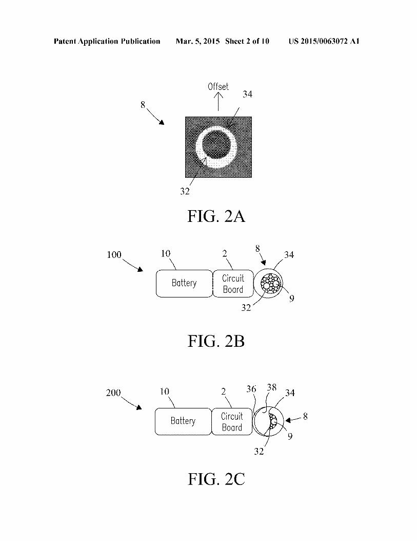
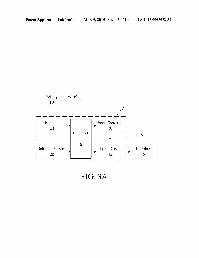
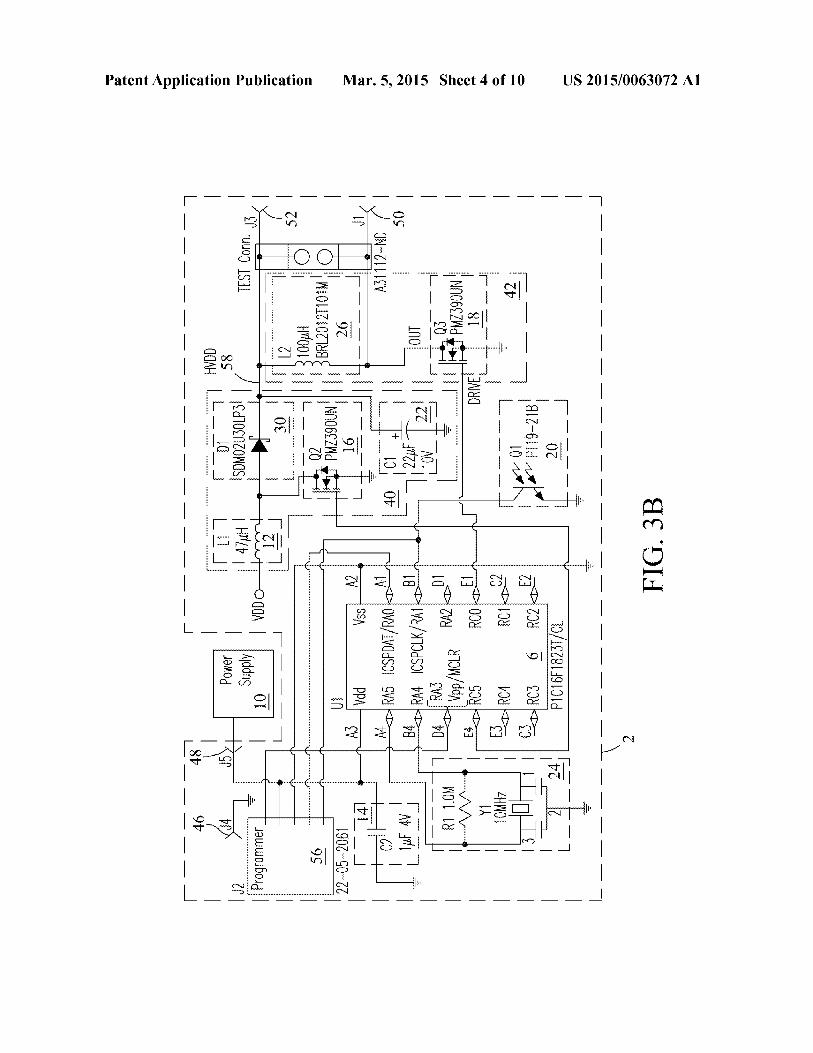
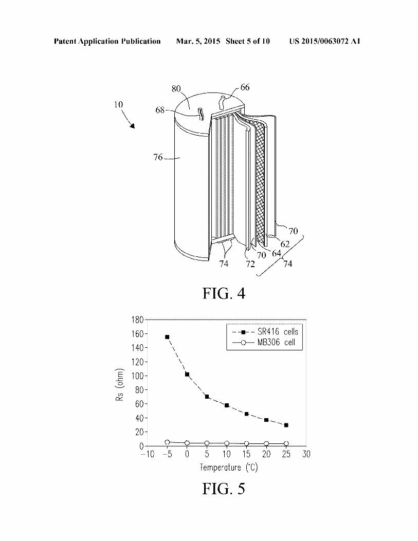
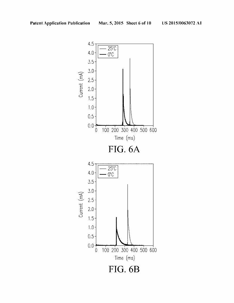
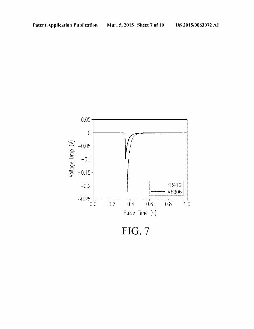
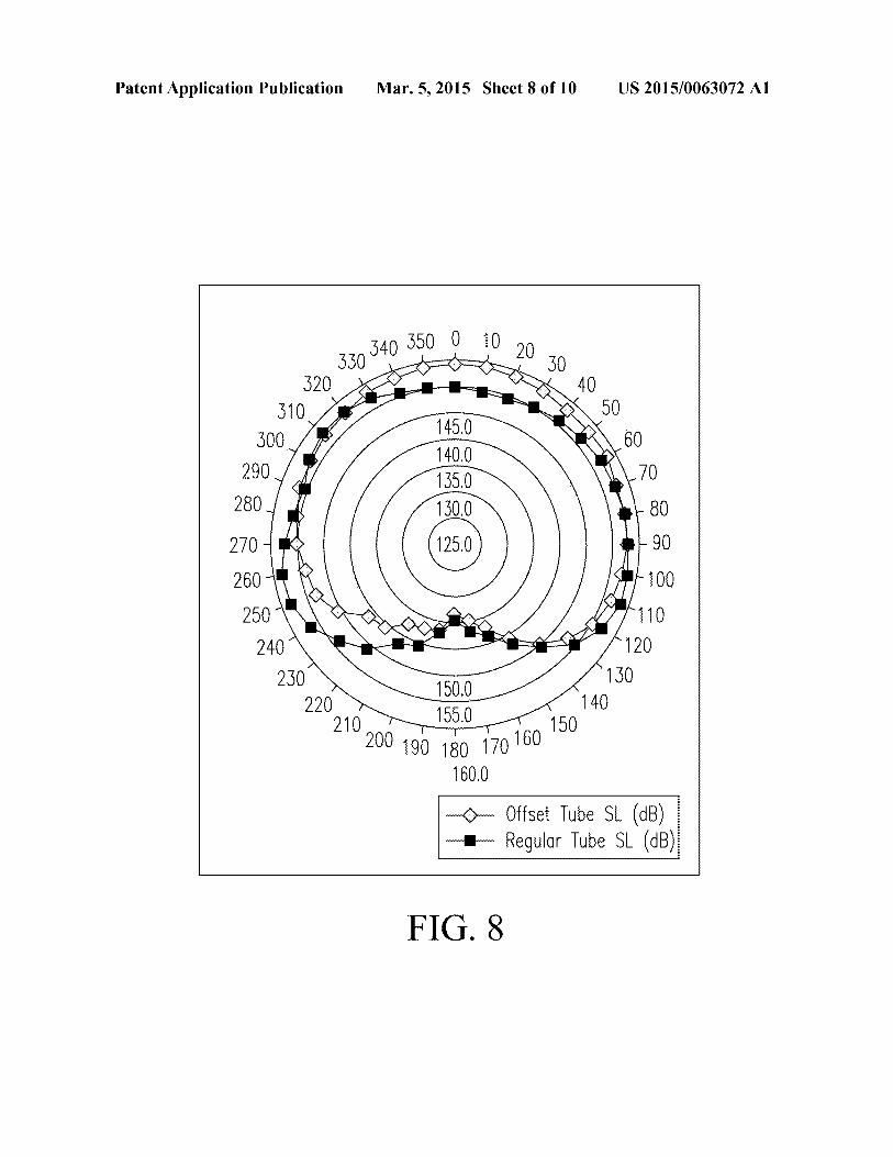
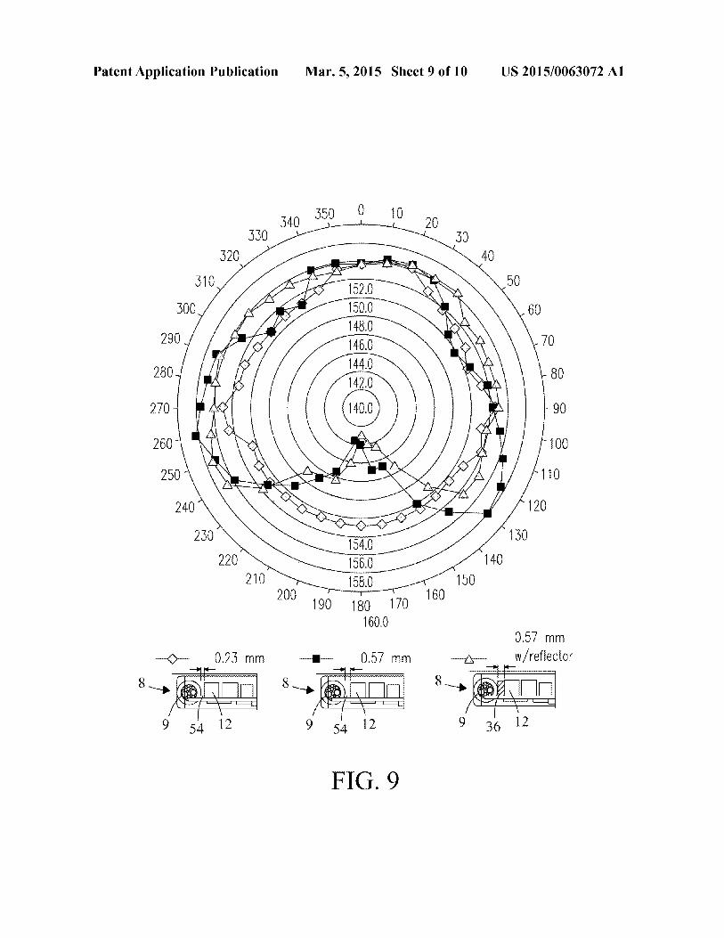
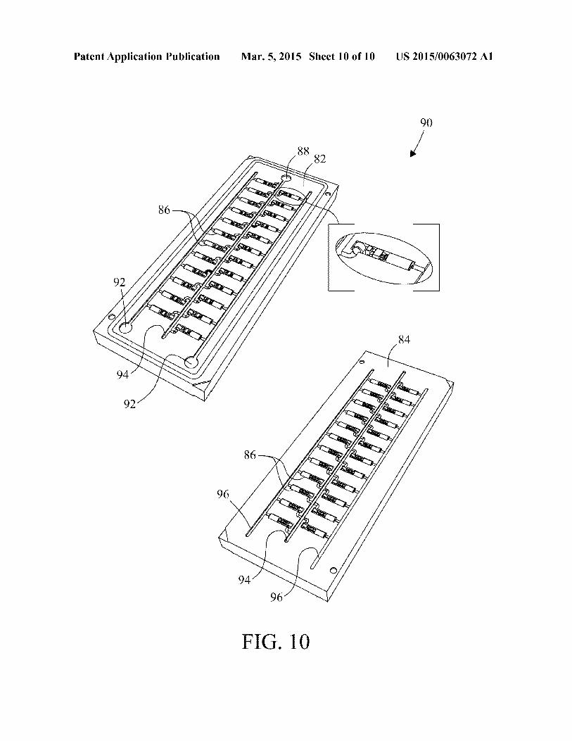
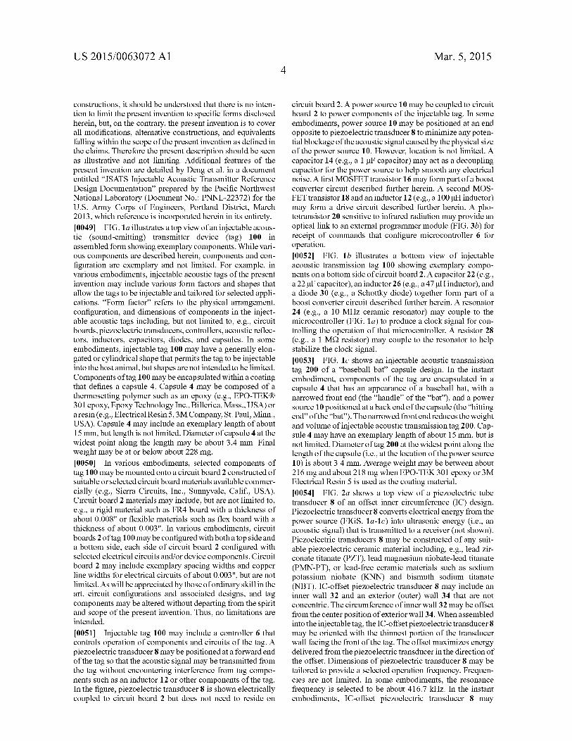
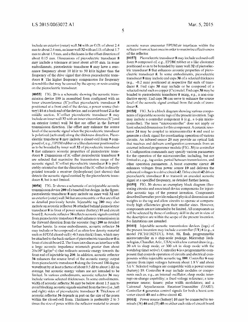
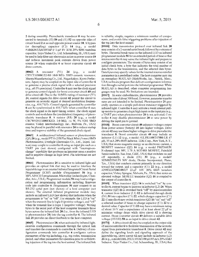
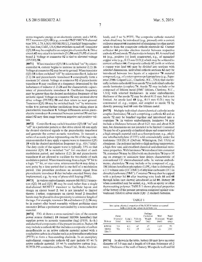
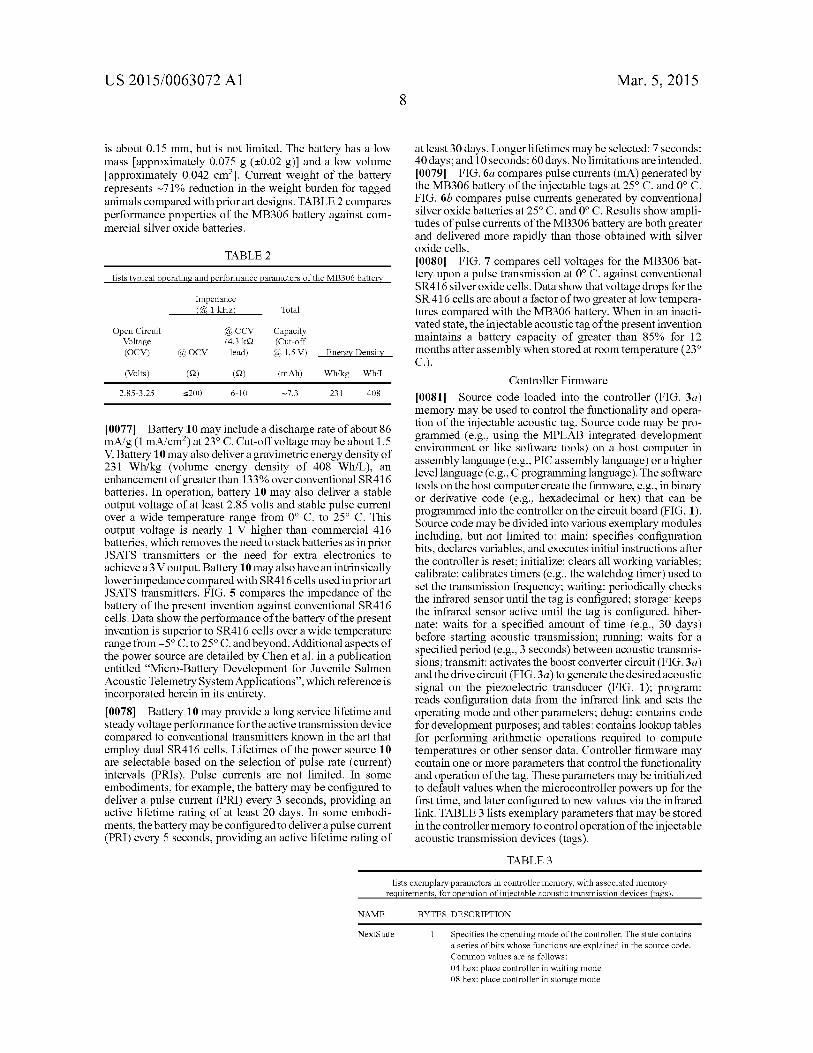
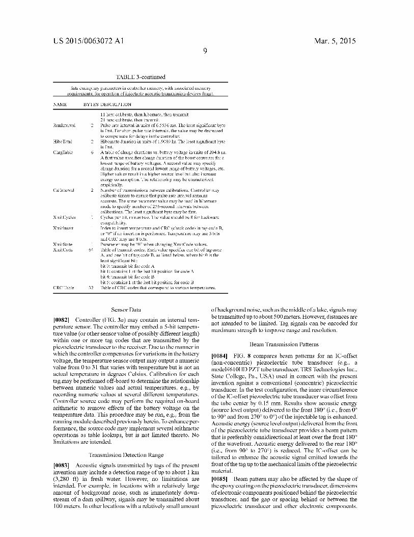
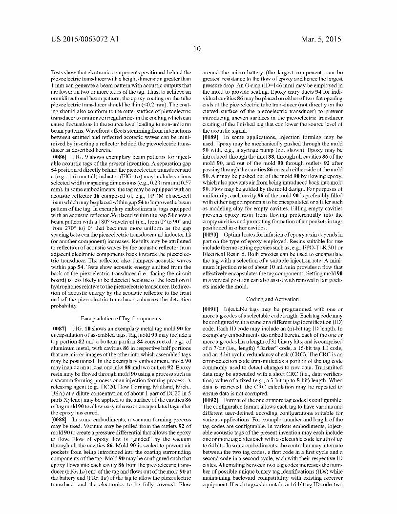
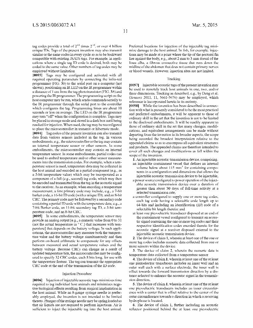