U AND H SHAPED STACKED MICROSTRIP PATCH … · c. Radiation pattern in 2D view: Radiation pattern...
5
P.Poorna priya, A.Srujana, D. Vinay Kumar, K.Rajasekhar / International Journal of Engineering Research and Applications (IJERA) ISSN: 2248-9622 www.ijera.com Vol. 2, Issue 3, May-Jun 2012, pp. 586-590 586 | P a g e U AND H SHAPED STACKED MICROSTRIP PATCH ANTENNA FOR C AND X BAND APPLICATIONS P.Poorna priya * , A.Srujana**, D. Vinay Kumar**, K.Rajasekhar** * Assoc.Professor ,Department of ECE, K L University, Guntur District, AP, India ** Students, Department of ECE, K L University, Guntur District, AP, Indi a ABSTRACT: The C and X band ranges of operation have wide range of applications which include satellite communications, Terrestrial communications and motion detection. In this paper we simulated and presented the results of radiation pattern, return loss, power dissipation and quality factor of stacked Microstrip patch antenna which operates in C and X bands. The results of antenna are simulated by using Concerto software. This antenna consists of a U-slot loaded patch stacked with H shaped parasitic patch which exhibits dual frequency of operation. I. INTRODUCTION Microstrip patch antennas, in spite of having advantages like light weight, low profile, compact and cost effective, they also have disadvantages of narrow bandwidth and low gain. To overcome these disadvantages we employed stacked patch due to its capability of providing dual frequency characteristics and wider bandwidth. Here we contain two patches one is a U-slot loaded rectangular patch of area 39.4 X 29.4 mm and other is a parasitic H- shaped patch of area 26 X 18 mm. A combination of these two resulted in a dual frequency of operation with a low return loss , thus antenna will be having maximum power transmission. Generally for good antenna performance a thick dielectric substrate having a low dielectric constant is preferred. The substrate we selected here is RT DUROID as this provides better efficiency, larger bandwidth and better radiation. Of all the types of RT DUROID we selected RT DUROID 5880 of dielectric constant 2.2 in order to obtain better return loss. Hence for lower patch we use RT DUROID substrate of dielectric constant 2.2 and for stacked patch the substrate is air, dielectric constant is 1. Thus by employing stacked patches, substrates with low dielectric constant, proper feed location we are able to obtain dual frequency of operation with minimum return loss. The software Concerto is a state of the art system for high frequency field simulation. The main components of this are modeller, quick wave simulator, quickwave2D, CLASP, SOPRANO/EV and post processor. Concerto provides a complete tool chain for RF and microwave electromagnetic design for use on 32 or 64 bit windows platform. Concerto Modeller is used to generate data and models for electromagnetic simulation. The Quick wave simulator uses a finite difference time domain (FDTD) method with conforming elements ideally suited to the analysis of microwave devices. Quick wave 2D also uses FDTD to simulate asymmetric geometrics such as circular waveguides, horn antennas and coaxial connector. CLASP uses the method of moments (MOM) to calculate antenna radiation patterns. The post processor displays and performs further calculation results of CLASP analysis. II. DESIGN SPECIFICATION FOR PROPOSED ANTENNA: The geometry of proposed antenna is illustrated in fig (1) . It consists of a lower U-slot loaded patch fabricated on a 39.4 X 29.4 mm2 RT-Duroid substrate with a dielectric constant of €r=2.2 and a substrate thickness of t=6mm. The upper one is a H shaped stacked patch fabricated on a 26 X 18 mm2 AIR substrate with a dielectric constant of €r=1 and a substrate thickness of t=5.5mm.
Transcript of U AND H SHAPED STACKED MICROSTRIP PATCH … · c. Radiation pattern in 2D view: Radiation pattern...
P.Poorna priya, A.Srujana, D. Vinay Kumar, K.Rajasekhar / International Journal of Engineering
Research and Applications (IJERA) ISSN: 2248-9622 www.ijera.com
Vol. 2, Issue 3, May-Jun 2012, pp. 586-590
586 | P a g e
U AND H SHAPED STACKED MICROSTRIP PATCH
ANTENNA FOR C AND X BAND APPLICATIONS
P.Poorna priya*, A.Srujana**, D. Vinay Kumar**, K.Rajasekhar**
* Assoc.Professor ,Department of ECE, K L University, Guntur District, AP, India
** Students, Department of ECE, K L University, Guntur District, AP, India
ABSTRACT: The C and X band ranges of operation have wide range
of applications which include satellite communications,
Terrestrial communications and motion detection. In
this paper we simulated and presented the results of
radiation pattern, return loss, power dissipation and
quality factor of stacked Microstrip patch antenna which
operates in C and X bands. The results of antenna are
simulated by using Concerto software. This antenna
consists of a U-slot loaded patch stacked with H shaped
parasitic patch which exhibits dual frequency of
operation.
I. INTRODUCTION Microstrip patch antennas, in spite of having advantages
like light weight, low profile, compact and cost
effective, they also have disadvantages of narrow
bandwidth and low gain. To overcome these
disadvantages we employed stacked patch due to its
capability of providing dual frequency characteristics
and wider bandwidth.
Here we contain two patches one is a U-slot loaded
rectangular patch of area 39.4 X 29.4
mm and other is a parasitic H- shaped patch of area 26
X 18 mm. A combination of these two resulted in a dual
frequency of operation with a low return loss , thus
antenna will be
having maximum power transmission. Generally for
good antenna performance a thick dielectric substrate
having a low dielectric constant is preferred.
The substrate we selected here is RT DUROID as this
provides better efficiency,
larger bandwidth and better radiation. Of all the types of
RT DUROID we selected RT
DUROID 5880 of dielectric constant 2.2 in order to
obtain better return loss. Hence for lower patch we use
RT DUROID substrate of dielectric constant 2.2 and for
stacked patch the substrate is air, dielectric constant is 1.
Thus by employing stacked patches, substrates with
low dielectric constant, proper feed location we are able
to obtain dual frequency of operation with minimum
return loss.
The software Concerto is a state of the art system for
high frequency field simulation. The main components
of this are modeller, quick wave simulator,
quickwave2D, CLASP, SOPRANO/EV and post
processor. Concerto provides a complete tool chain for
RF and microwave electromagnetic design for use on 32
or 64 bit windows platform. Concerto Modeller is used
to generate data and models for electromagnetic
simulation. The Quick wave simulator uses a finite
difference time domain (FDTD) method with
conforming elements ideally suited to the analysis of
microwave devices. Quick wave 2D also uses FDTD to
simulate asymmetric geometrics such as circular
waveguides, horn antennas and coaxial connector.
CLASP uses the method of moments (MOM) to
calculate antenna radiation patterns. The post processor
displays and performs further calculation results of
CLASP analysis.
II. DESIGN SPECIFICATION FOR
PROPOSED ANTENNA: The geometry of proposed antenna is illustrated in fig
(1) . It consists of a lower U-slot loaded patch
fabricated on a 39.4 X 29.4 mm2 RT-Duroid substrate
with a dielectric constant of €r=2.2 and a substrate
thickness of t=6mm. The upper one is a H shaped
stacked patch fabricated on a 26 X 18 mm2
AIR substrate with a dielectric constant of €r=1 and a
substrate thickness of t=5.5mm.
P.Poorna priya, A.Srujana, D. Vinay Kumar, K.Rajasekhar / International Journal of Engineering
Research and Applications (IJERA) ISSN: 2248-9622 www.ijera.com
Vol. 2, Issue 3, May-Jun 2012, pp. 586-590
587 | P a g e
Fig 1: U and H shaped stacked microstrip
patch antenne block view
Fig 2: U and H shaped stacked microstrip
patch antenna detailed view
The antenna has following parameters U-slot length Ls
of 15mm, width Ws of 26mm and thickness s of
1.2mm. For the H-shaped patch length of cut slot d is
15mm and height Wn of 4mm. The feed location is
given by (0, -4.77). The inner radius of the coaxial feed
is 0.3mm and outer radius is 1mm.
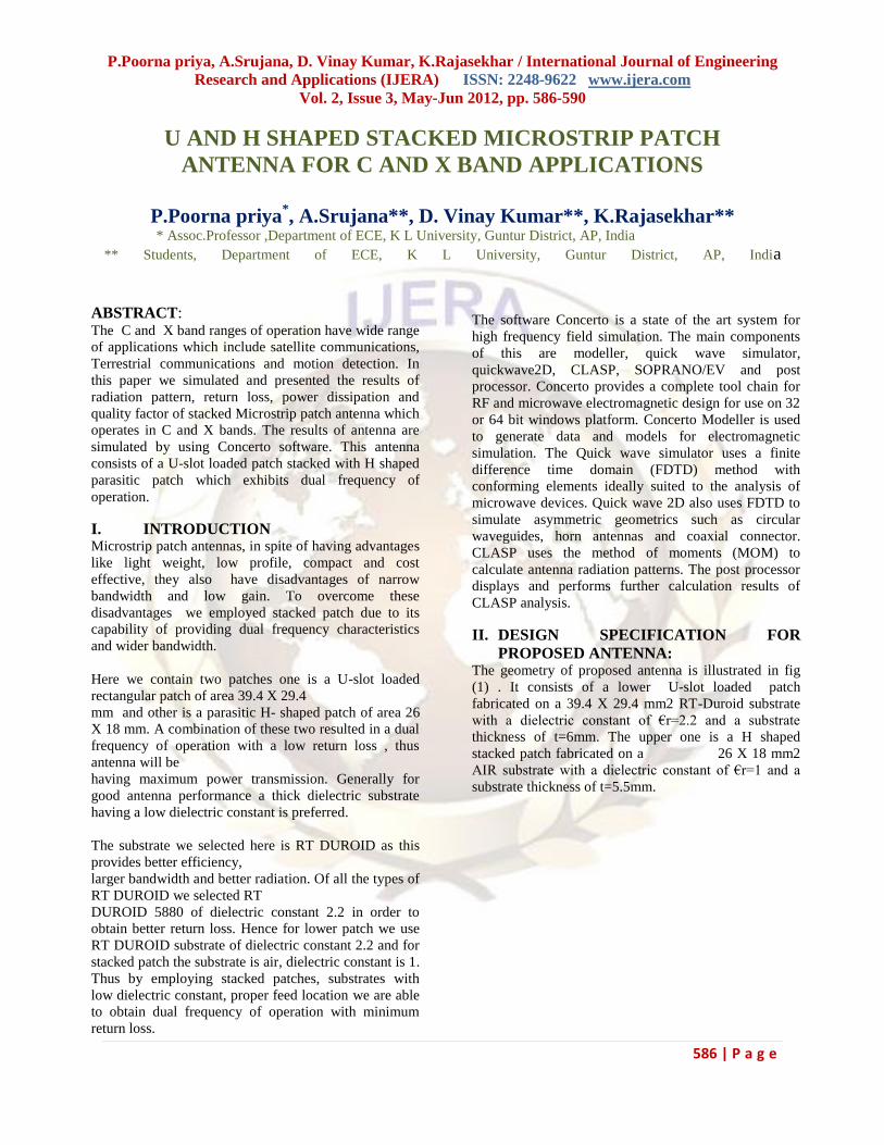
III.RESULTS AND DISCUSSIONS:
a. Return Loss :
The simulated results of return loss is shown in Fig
(3).The frequency range of this antenna is 4 GHz to
12 GHz(C and X band range).The return loss observed
for the designed model is -31.266dB at 7.66 GHz
operating frequency and -24.10542dB at 9.73 GHz
operating frequency.
Fig 3: Return loss
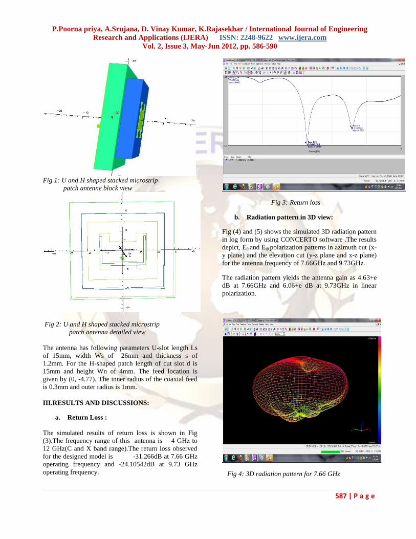
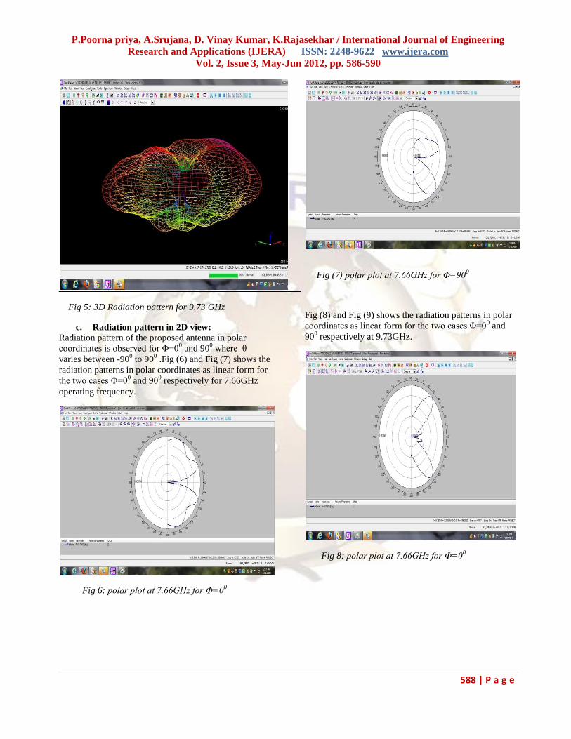
b. Radiation pattern in 3D view:
Fig (4) and (5) shows the simulated 3D radiation pattern
in log form by using CONCERTO software .The results
depict, Eθ and EΦ polarization patterns in azimuth cut (x-
y plane) and the elevation cut (y-z plane and x-z plane)
for the antenna frequency of 7.66GHz and 9.73GHz.
The radiation pattern yields the antenna gain as 4.63+e
dB at 7.66GHz and 6.06+e dB at 9.73GHz in linear
polarization.
Fig 4: 3D radiation pattern for 7.66 GHz
P.Poorna priya, A.Srujana, D. Vinay Kumar, K.Rajasekhar / International Journal of Engineering
Research and Applications (IJERA) ISSN: 2248-9622 www.ijera.com
Vol. 2, Issue 3, May-Jun 2012, pp. 586-590
588 | P a g e
Fig 5: 3D Radiation pattern for 9.73 GHz
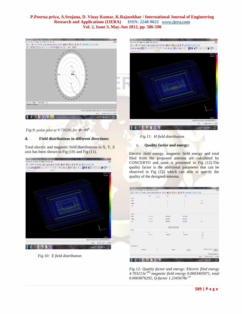
c. Radiation pattern in 2D view: Radiation pattern of the proposed antenna in polar
coordinates is observed for Φ=00 and 90
0 where θ
varies between -900 to 90
0 .Fig (6) and Fig (7) shows the
radiation patterns in polar coordinates as linear form for
the two cases Φ=00 and 90
0 respectively for 7.66GHz
operating frequency.
Fig 6: polar plot at 7.66GHz for Φ=00
Fig (7) polar plot at 7.66GHz for Φ=900
Fig (8) and Fig (9) shows the radiation patterns in polar
coordinates as linear form for the two cases Φ=00 and
900 respectively at 9.73GHz.
Fig 8: polar plot at 7.66GHz for Φ=00
P.Poorna priya, A.Srujana, D. Vinay Kumar, K.Rajasekhar / International Journal of Engineering
Research and Applications (IJERA) ISSN: 2248-9622 www.ijera.com
Vol. 2, Issue 3, May-Jun 2012, pp. 586-590
589 | P a g e
Fig 9: polar plot at 9.73GHz for Φ=900
d. Field distributions in different directions:
Total electric and magnetic field distributions in X, Y, Z
axis has been shown in Fig (10) and Fig (11).
Fig 10: E field distribution
Fig 11: H field distribution
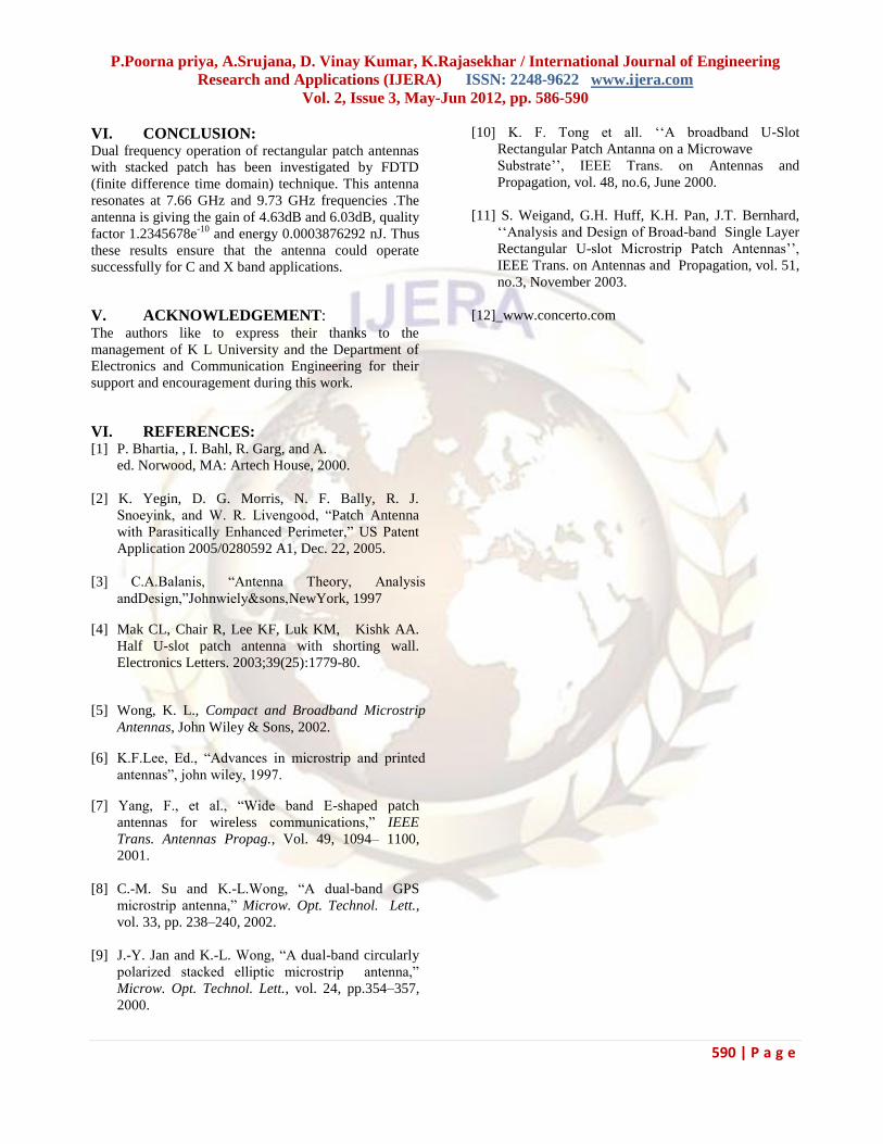
e. Quality factor and energy:
Electric field energy, magnetic field energy and total
filed from the proposed antenna are calculated by
CONCERTO and same is presented in Fig (12).The
quality factor is the additional parameter that can be
observed in Fig (12) which can able to specify the
quality of the designed antenna.
Fig 12: Quality factor and energy: Electric filed energy
4.703213e-005
magnetic field energy 0.0003405971, total
0.0003876292, Q-factor 1.2345678e-10
P.Poorna priya, A.Srujana, D. Vinay Kumar, K.Rajasekhar / International Journal of Engineering
Research and Applications (IJERA) ISSN: 2248-9622 www.ijera.com
Vol. 2, Issue 3, May-Jun 2012, pp. 586-590
590 | P a g e
VI. CONCLUSION: Dual frequency operation of rectangular patch antennas
with stacked patch has been investigated by FDTD
(finite difference time domain) technique. This antenna
resonates at 7.66 GHz and 9.73 GHz frequencies .The
antenna is giving the gain of 4.63dB and 6.03dB, quality
factor 1.2345678e-10
and energy 0.0003876292 nJ. Thus
these results ensure that the antenna could operate
successfully for C and X band applications.
V. ACKNOWLEDGEMENT: The authors like to express their thanks to the
management of K L University and the Department of
Electronics and Communication Engineering for their
support and encouragement during this work.
VI. REFERENCES: [1] P. Bhartia, , I. Bahl, R. Garg, and A.
ed. Norwood, MA: Artech House, 2000.
[2] K. Yegin, D. G. Morris, N. F. Bally, R. J.
Snoeyink, and W. R. Livengood, “Patch Antenna
with Parasitically Enhanced Perimeter,” US Patent
Application 2005/0280592 A1, Dec. 22, 2005.
[3] C.A.Balanis, “Antenna Theory, Analysis
andDesign,”Johnwiely&sons,NewYork, 1997
[4] Mak CL, Chair R, Lee KF, Luk KM, Kishk AA.
Half U-slot patch antenna with shorting wall.
Electronics Letters. 2003;39(25):1779-80.
[5] Wong, K. L., Compact and Broadband Microstrip
Antennas, John Wiley & Sons, 2002.
[6] K.F.Lee, Ed., “Advances in microstrip and printed
antennas”, john wiley, 1997.
[7] Yang, F., et al., “Wide band E-shaped patch
antennas for wireless communications,” IEEE
Trans. Antennas Propag., Vol. 49, 1094– 1100,
2001.
[8] C.-M. Su and K.-L.Wong, “A dual-band GPS
microstrip antenna,” Microw. Opt. Technol. Lett.,
vol. 33, pp. 238–240, 2002.
[9] J.-Y. Jan and K.-L. Wong, “A dual-band circularly
polarized stacked elliptic microstrip antenna,”
Microw. Opt. Technol. Lett., vol. 24, pp.354–357,
2000.
[10] K. F. Tong et all. „„A broadband U-Slot
Rectangular Patch Antanna on a Microwave
Substrate‟‟, IEEE Trans. on Antennas and
Propagation, vol. 48, no.6, June 2000.
[11] S. Weigand, G.H. Huff, K.H. Pan, J.T. Bernhard,
„„Analysis and Design of Broad-band Single Layer
Rectangular U-slot Microstrip Patch Antennas‟‟,
IEEE Trans. on Antennas and Propagation, vol. 51,
no.3, November 2003.
[12] www.concerto.com
![Antennas for Bases and Mobiles - Técnico Lisboa ... · PDF filenamely concerning the radiation pattern. ... Kathrein., 1999] Vertical plane. Mobile Comms. ... • The user influences](https://static.fdocument.org/doc/165x107/5a6fd3517f8b9aa7538b6f48/antennas-for-bases-and-mobiles-tcnico-lisboa-nbsppdf-filenamely.jpg)