Triacs BT138 series - Frank's Hospital Workshop€¦ · Philips Semiconductors Product...
6
Philips Semiconductors Product specification Triacs BT138 series GENERAL DESCRIPTION QUICK REFERENCE DATA Glass passivated triacs in a plastic SYMBOL PARAMETER MAX. MAX. MAX. UNIT envelope, intended for use in applications requiring high BT138- 500 600 800 bidirectional transient and blocking BT138- 500F 600F 800F voltage capability and high thermal BT138- 500G 600G 800G cycling performance. Typical V DRM Repetitive peak off-state 500 600 800 V applications include motor control, voltages industrial and domestic lighting, I T(RMS) RMS on-state current 12 12 12 A heating and static switching. I TSM Non-repetitive peak on-state 95 95 95 A current PINNING - TO220AB PIN CONFIGURATION SYMBOL PIN DESCRIPTION 1 main terminal 1 2 main terminal 2 3 gate tab main terminal 2 LIMITING VALUES Limiting values in accordance with the Absolute Maximum System (IEC 134). SYMBOL PARAMETER CONDITIONS MIN. MAX. UNIT -500 -600 -800 V DRM Repetitive peak off-state - 500 1 600 1 800 V voltages I T(RMS) RMS on-state current full sine wave; T mb ≤ 99 ˚C - 12 A I TSM Non-repetitive peak full sine wave; T j = 25 ˚C prior to on-state current surge t = 20 ms - 95 A t = 16.7 ms - 105 A I 2 t I 2 t for fusing t = 10 ms - 45 A 2 s dI T /dt Repetitive rate of rise of I TM = 20 A; I G = 0.2 A; on-state current after dI G /dt = 0.2 A/μs triggering T2+ G+ - 50 A/μs T2+ G- - 50 A/μs T2- G- - 50 A/μs T2- G+ - 10 A/μs I GM Peak gate current - 2 A V GM Peak gate voltage - 5 V P GM Peak gate power - 5 W P G(AV) Average gate power over any 20 ms period - 0.5 W T stg Storage temperature -40 150 ˚C T j Operating junction - 125 ˚C temperature T1 T2 G 123 tab 1 Although not recommended, off-state voltages up to 800V may be applied without damage, but the triac may switch to the on-state. The rate of rise of current should not exceed 15 A/μs. September 1997 1 Rev 1.200
Transcript of Triacs BT138 series - Frank's Hospital Workshop€¦ · Philips Semiconductors Product...

Philips Semiconductors Product specification
Triacs BT138 series
GENERAL DESCRIPTION QUICK REFERENCE DATA
Glass passivated triacs in a plastic SYMBOL PARAMETER MAX. MAX. MAX. UNITenvelope, intended for use inapplications requiring high BT138- 500 600 800bidirectional transient and blocking BT138- 500F 600F 800Fvoltage capability and high thermal BT138- 500G 600G 800Gcycling performance. Typical VDRM Repetitive peak off-state 500 600 800 Vapplications include motor control, voltagesindustrial and domestic lighting, IT(RMS) RMS on-state current 12 12 12 Aheating and static switching. ITSM Non-repetitive peak on-state 95 95 95 A
current
PINNING - TO220AB PIN CONFIGURATION SYMBOL
PIN DESCRIPTION
1 main terminal 1
2 main terminal 2
3 gate
tab main terminal 2
LIMITING VALUESLimiting values in accordance with the Absolute Maximum System (IEC 134).
SYMBOL PARAMETER CONDITIONS MIN. MAX. UNIT
-500 -600 -800VDRM Repetitive peak off-state - 5001 6001 800 V
voltages
IT(RMS) RMS on-state current full sine wave; Tmb ≤ 99 ˚C - 12 AITSM Non-repetitive peak full sine wave; Tj = 25 ˚C prior to
on-state current surget = 20 ms - 95 At = 16.7 ms - 105 A
I2t I2t for fusing t = 10 ms - 45 A2sdIT/dt Repetitive rate of rise of ITM = 20 A; IG = 0.2 A;
on-state current after dIG/dt = 0.2 A/µstriggering T2+ G+ - 50 A/µs
T2+ G- - 50 A/µsT2- G- - 50 A/µsT2- G+ - 10 A/µs
IGM Peak gate current - 2 AVGM Peak gate voltage - 5 VPGM Peak gate power - 5 WPG(AV) Average gate power over any 20 ms period - 0.5 WTstg Storage temperature -40 150 ˚CTj Operating junction - 125 ˚C
temperature
T1T2
G1 2 3
tab
1 Although not recommended, off-state voltages up to 800V may be applied without damage, but the triac mayswitch to the on-state. The rate of rise of current should not exceed 15 A/µs.
September 1997 1 Rev 1.200

Philips Semiconductors Product specification
Triacs BT138 series
THERMAL RESISTANCESSYMBOL PARAMETER CONDITIONS MIN. TYP. MAX. UNIT
Rth j-mb Thermal resistance full cycle - - 1.5 K/Wjunction to mounting base half cycle - - 2.0 K/W
Rth j-a Thermal resistance in free air - 60 - K/Wjunction to ambient
STATIC CHARACTERISTICSTj = 25 ˚C unless otherwise stated
SYMBOL PARAMETER CONDITIONS MIN. TYP. MAX. UNIT
BT138- ... ...F ...GIGT Gate trigger current VD = 12 V; IT = 0.1 A
T2+ G+ - 5 35 25 50 mAT2+ G- - 8 35 25 50 mAT2- G- - 10 35 25 50 mAT2- G+ - 22 70 70 100 mA
IL Latching current VD = 12 V; IGT = 0.1 AT2+ G+ - 7 40 40 60 mAT2+ G- - 20 60 60 90 mAT2- G- - 8 40 40 60 mAT2- G+ - 10 60 60 90 mA
IH Holding current VD = 12 V; IGT = 0.1 A - 6 30 30 60 mA
VT On-state voltage IT = 15 A - 1.4 1.65 VVGT Gate trigger voltage VD = 12 V; IT = 0.1 A - 0.7 1.5 V
VD = 400 V; IT = 0.1 A; 0.25 0.4 - VTj = 125 ˚C
ID Off-state leakage current VD = VDRM(max); - 0.1 0.5 mATj = 125 ˚C
DYNAMIC CHARACTERISTICSTj = 25 ˚C unless otherwise stated
SYMBOL PARAMETER CONDITIONS MIN. TYP. MAX. UNIT
BT138- ... ...F ...GdVD/dt Critical rate of rise of VDM = 67% VDRM(max); 100 50 200 250 - V/µs
off-state voltage Tj = 125 ˚C; exponentialwaveform; gate opencircuit
dVcom/dt Critical rate of change of VDM = 400 V; Tj = 95 ˚C; - - 10 20 - V/µscommutating voltage IT(RMS) = 12 A;
dIcom/dt = 5.4 A/ms; gateopen circuit
tgt Gate controlled turn-on ITM = 16 A; VD = VDRM(max); - - - 2 - µstime IG = 0.1 A; dIG/dt = 5 A/µs
September 1997 2 Rev 1.200

Philips Semiconductors Product specification
Triacs BT138 series
Fig.1. Maximum on-state dissipation, Ptot, versus rmson-state current, IT(RMS), where α = conduction angle.
Fig.2. Maximum permissible non-repetitive peakon-state current ITSM, versus pulse width tp, for
sinusoidal currents, tp ≤ 20ms.
Fig.3. Maximum permissible non-repetitive peakon-state current ITSM, versus number of cycles, for
sinusoidal currents, f = 50 Hz.
Fig.4. Maximum permissible rms current IT(RMS) ,versus mounting base temperature Tmb.
Fig.5. Maximum permissible repetitive rms on-statecurrent IT(RMS), versus surge duration, for sinusoidal
currents, f = 50 Hz; Tmb ≤ 99˚C.
Fig.6. Normalised gate trigger voltageVGT(Tj)/ VGT(25˚C), versus junction temperature Tj.
0 5 10 150
5
10
15
20
= 180
120
90
60
30
BT138
IT(RMS) / A
Ptot / W Tmb(max) / C
125
117.5
110
102.5
95
1
-50 0 50 100 1500
5
10
15BT138
99 C
Tmb / C
IT(RMS) / A
10us 100us 1ms 10ms 100ms10
100
1000BT138
T / s
ITSM / A
TITSM
time
I
Tj initial = 25 C max
T
dI /dt limitT
T2- G+ quadrant
0.01 0.1 1 100
5
10
15
20
25BT138
surge duration / s
IT(RMS) / A
1 10 100 10000
20
40
60
80
100BT138
Number of cycles at 50Hz
ITSM / A
TITSM
time
I
Tj initial = 25 C max
T
-50 0 50 100 1500.4
0.6
0.8
1
1.2
1.4
1.6BT136
Tj / C
VGT(Tj)VGT(25 C)
September 1997 3 Rev 1.200
Philips Semiconductors Product specification
Triacs BT138 series
Fig.7. Normalised gate trigger currentIGT(Tj)/ IGT(25˚C), versus junction temperature Tj.
Fig.8. Normalised latching current IL(Tj)/ IL(25˚C),versus junction temperature Tj.
Fig.9. Normalised holding current IH(Tj)/ IH(25˚C),versus junction temperature Tj.
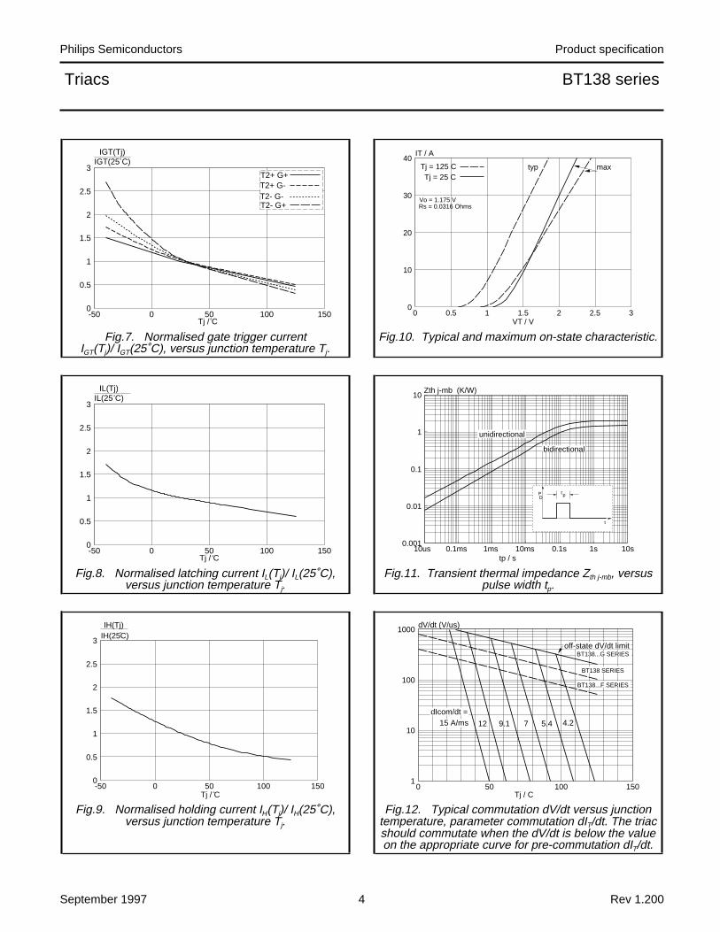
Fig.10. Typical and maximum on-state characteristic.
Fig.11. Transient thermal impedance Zth j-mb, versuspulse width tp.
Fig.12. Typical commutation dV/dt versus junctiontemperature, parameter commutation dIT/dt. The triacshould commutate when the dV/dt is below the valueon the appropriate curve for pre-commutation dIT/dt.
-50 0 50 100 1500
0.5
1
1.5
2
2.5
3BT138
Tj / C
T2+ G+T2+ G-T2- G-T2- G+
IGT(Tj)IGT(25 C)
0 0.5 1 1.5 2 2.5 30
10
20
30
40BT138
VT / V
IT / A
Tj = 125 CTj = 25 C
typ max
Vo = 1.175 VRs = 0.0316 Ohms
-50 0 50 100 1500
0.5
1
1.5
2
2.5
3TRIAC
Tj / C
IL(Tj)IL(25 C)
0.001
0.01
0.1
1
10BT138
tp / s
Zth j-mb (K/W)
10us 0.1ms 1ms 10ms 0.1s 1s 10s
tpP
t
D
bidirectional
unidirectional
-50 0 50 100 1500
0.5
1
1.5
2
2.5
3TRIAC
Tj / C
IH(Tj)IH(25C)
0 50 100 1501
10
100
1000
5.49.1
Tj / C
7
dV/dt (V/us)
4.2dIcom/dt =
15 A/ms 12
off-state dV/dt limitBT138...G SERIES
BT138 SERIES
BT138...F SERIES
September 1997 4 Rev 1.200

Philips Semiconductors Product specification
Triacs BT138 series
MECHANICAL DATA
Dimensions in mm
Net Mass: 2 g
Fig.13. TO220AB; pin 2 connected to mounting base.
Notes1. Refer to mounting instructions for TO220 envelopes.2. Epoxy meets UL94 V0 at 1/8".
10,3max
3,7
2,8
3,03,0 maxnot tinned
1,3max(2x)
1 2 3
2,40,6
4,5max
5,9min
15,8max
1,3
2,54 2,54
0,9 max (3x)
13,5min
September 1997 5 Rev 1.200

Philips Semiconductors Product specification
Triacs BT138 series
DEFINITIONS
Data sheet status
Objective specification This data sheet contains target or goal specifications for product development.
Preliminary specification This data sheet contains preliminary data; supplementary data may be published later.
Product specification This data sheet contains final product specifications.
Limiting values
Limiting values are given in accordance with the Absolute Maximum Rating System (IEC 134). Stress above oneor more of the limiting values may cause permanent damage to the device. These are stress ratings only andoperation of the device at these or at any other conditions above those given in the Characteristics sections ofthis specification is not implied. Exposure to limiting values for extended periods may affect device reliability.
Application information
Where application information is given, it is advisory and does not form part of the specification.
Philips Electronics N.V. 1997
All rights are reserved. Reproduction in whole or in part is prohibited without the prior written consent of thecopyright owner.
The information presented in this document does not form part of any quotation or contract, it is believed to beaccurate and reliable and may be changed without notice. No liability will be accepted by the publisher for anyconsequence of its use. Publication thereof does not convey nor imply any license under patent or otherindustrial or intellectual property rights.
LIFE SUPPORT APPLICATIONSThese products are not designed for use in life support appliances, devices or systems where malfunction of theseproducts can be reasonably expected to result in personal injury. Philips customers using or selling these productsfor use in such applications do so at their own risk and agree to fully indemnify Philips for any damages resultingfrom such improper use or sale.
September 1997 6 Rev 1.200