TM GAMMA BRACING TECHNOLGIES LIMITEDgammabracing.co.nz/images/downloads/GAMMA_BRACING_FRAME...s TM s...
52
γ TM GAMMA BRACING TECHNOLGIES LIMITED GAMMA γ TM NEW ZEALAND’S MOST ADVANCED BRACING SYSTEM FOR TIMBER FRAME CONSTRUCTIONS ISSUE MARCH 2019 TECHNICAL INSTALLATION MANUAL DESIGNED BY GAMMA TECHNOLOGIES LTD Copyright 2014 GBF220 GBF400 GBF600
Transcript of TM GAMMA BRACING TECHNOLGIES LIMITEDgammabracing.co.nz/images/downloads/GAMMA_BRACING_FRAME...s TM s...

γ TM
GAMMABRACING TECHNOLGIES LIMITED
GAMMAγ TM
NEW ZEALAND’S MOST ADVANCED BRACING SYSTEM FOR TIMBER FRAME CONSTRUCTIONS
ISSUE MARCH 2019
TECHNICAL INSTALLATION MANUAL
DESIGNED BY GAMMA TECHNOLOGIES LTDCopyright 2014 GBF220 GBF400 GBF600
γ TM
GAMMAγ TM
2
P R O O F1.0 General Information1. Gamma withstands multiple wind and/or earthquake
traumas and maintains its structural integrity.
2. Gamma has a high “Ductility” so it can flex without failure.
3. Gamma’s are best installed early in the construction to immediately provide bracing performance.
4. Gamma’s eliminate the majority of temporary bracing.
5. It’s fast and easy to install either onsite or in a frame & truss plant.
6. Gamma comes with pre-punched fixing & service holes.
7. Gamma’s are lightweight and of a robust construction (12.5kg).
8. Gamma’s are suitable for remedial work for buildings affected by leaky building syndrome.
9. Gamma’s can be installed in wet area’s and area’s where no linings are installed.
10. Gamma’s provide up to 150 Bu’s per metre (1 kN = 20 BU’s).
11. Gamma’s have a conditional 50 year B2 durability.
12. Gamma’s are cost competitive within the total construction costs.
13. Gamma’s are suitable for standard timber framing, either 600, or 400/450 or 220mm stud widths.
14. Effective on both Concrete and Timber bases.
15. Designed and manufactured for New Zealand environments.
16. 100% Recycable so very small environmental footprint.
17. Will provide structural bracing for the lifetime of the building.
18. It is fully compliant with New Zealand Building Codes.
19. Gamma’s may be used in combination with other bracing systems, eg. plasterboard and plywood.
1.0 General Information
γ TM
GAMMAγ TM
3
P R O O F
Contents
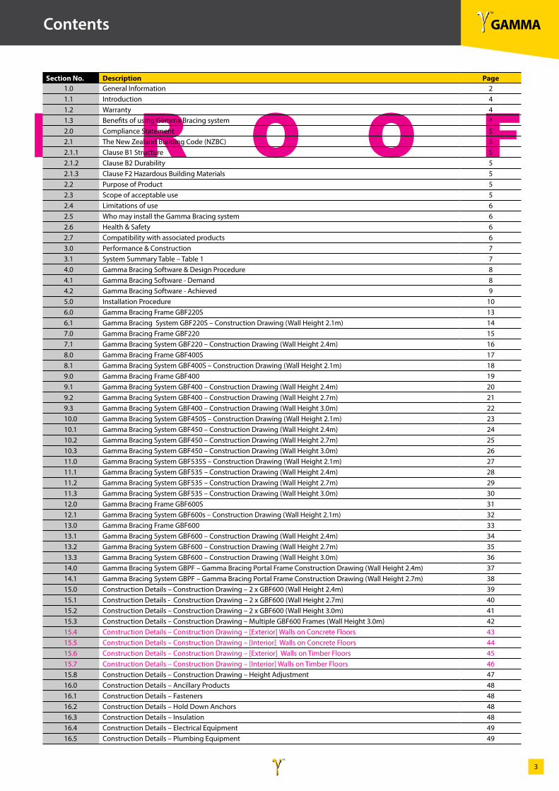
Section No. Description Page1.0 General Information 21.1 Introduction 41.2 Warranty 41.3 Benefits of using Gamma Bracing system 42.0 Compliance Statement 52.1 The New Zealand Building Code (NZBC) 52.1.1 Clause B1 Structure 52.1.2 Clause B2 Durability 52.1.3 Clause F2 Hazardous Building Materials 52.2 Purpose of Product 52.3 Scope of acceptable use 52.4 Limitations of use 62.5 Who may install the Gamma Bracing system 62.6 Health & Safety 62.7 Compatibility with associated products 63.0 Performance & Construction 73.1 System Summary Table – Table 1 74.0 Gamma Bracing Software & Design Procedure 84.1 Gamma Bracing Software - Demand 84.2 Gamma Bracing Software - Achieved 95.0 Installation Procedure 106.0 Gamma Bracing Frame GBF220S 136.1 Gamma Bracing System GBF220S – Construction Drawing (Wall Height 2.1m) 147.0 Gamma Bracing Frame GBF220 157.1 Gamma Bracing System GBF220 – Construction Drawing (Wall Height 2.4m) 168.0 Gamma Bracing Frame GBF400S 178.1 Gamma Bracing System GBF400S – Construction Drawing (Wall Height 2.1m) 189.0 Gamma Bracing Frame GBF400 199.1 Gamma Bracing System GBF400 – Construction Drawing (Wall Height 2.4m) 209.2 Gamma Bracing System GBF400 – Construction Drawing (Wall Height 2.7m) 219.3 Gamma Bracing System GBF400 – Construction Drawing (Wall Height 3.0m) 2210.0 Gamma Bracing System GBF450S – Construction Drawing (Wall Height 2.1m) 2310.1 Gamma Bracing System GBF450 – Construction Drawing (Wall Height 2.4m) 2410.2 Gamma Bracing System GBF450 – Construction Drawing (Wall Height 2.7m) 2510.3 Gamma Bracing System GBF450 – Construction Drawing (Wall Height 3.0m) 2611.0 Gamma Bracing System GBF535S – Construction Drawing (Wall Height 2.1m) 2711.1 Gamma Bracing System GBF535 – Construction Drawing (Wall Height 2.4m) 2811.2 Gamma Bracing System GBF535 – Construction Drawing (Wall Height 2.7m) 2911.3 Gamma Bracing System GBF535 – Construction Drawing (Wall Height 3.0m) 3012.0 Gamma Bracing Frame GBF600S 3112.1 Gamma Bracing System GBF600s – Construction Drawing (Wall Height 2.1m) 3213.0 Gamma Bracing Frame GBF600 3313.1 Gamma Bracing System GBF600 – Construction Drawing (Wall Height 2.4m) 3413.2 Gamma Bracing System GBF600 – Construction Drawing (Wall Height 2.7m) 3513.3 Gamma Bracing System GBF600 – Construction Drawing (Wall Height 3.0m) 3614.0 Gamma Bracing System GBPF – Gamma Bracing Portal Frame Construction Drawing (Wall Height 2.4m) 3714.1 Gamma Bracing System GBPF – Gamma Bracing Portal Frame Construction Drawing (Wall Height 2.7m) 3815.0 Construction Details – Construction Drawing – 2 x GBF600 (Wall Height 2.4m) 3915.1 Construction Details - Construction Drawing – 2 x GBF600 (Wall Height 2.7m) 4015.2 Construction Details – Construction Drawing – 2 x GBF600 (Wall Height 3.0m) 4115.3 Construction Details – Construction Drawing – Multiple GBF600 Frames (Wall Height 3.0m) 4215.4 Construction Details – Construction Drawing – [Exterior] Walls on Concrete Floors 4315.5 Construction Details – Construction Drawing – [Interior] Walls on Concrete Floors 4415.6 Construction Details – Construction Drawing – [Exterior] Walls on Timber Floors 4515.7 Construction Details – Construction Drawing – [Interior] Walls on Timber Floors 4615.8 Construction Details – Construction Drawing – Height Adjustment 4716.0 Construction Details – Ancillary Products 4816.1 Construction Details – Fasteners 4816.2 Construction Details – Hold Down Anchors 4816.3 Construction Details – Insulation 4816.4 Construction Details – Electrical Equipment 4916.5 Construction Details – Plumbing Equipment 49
γ TM
GAMMAγ TM
4
P R O O F
1.0 General Information
1.1. Introduction
Gamma Bracing system technology has been specifically designed and rigorously tested in New Zealand to provide structural bracing for both residential and light commercial buildings within the scope and limitations of NZS3604:2011.
The Gamma Bracing System has been tested in accordance with the New Zealand Building Code, verification method B1/VM p21 {2010} racking test limited states design; cited in NZS3604 Timber Framed Buildings to determine wind and earthquake ratings of bracing elements. This aligns with the new loadings standard AS/NZS 1170.
CodeMark Certification
Having met New Zealand’s stringent standards, the Gamma Bracing system is the future solution for wall bracing requirements within timber framed buildings.
1.2. Warranty
The Gamma Bracing system carries the following warranty. This warranty is given by Gamma Bracing Technology Ltd (“The Manufacturer”)
The manufacturer warrants that the products produced by the manufacturer shall be free of defects in materials and manufacture. If the products produced by the manufacturer do not meet the manufacturers standards, they will replace with the equivalent product. The manufacturer advises that only products, components and systems recommended by Gamma Bracing Technologies Ltd be used. At all times these must be used in accordance with the relevant product manufacturers usage recommendations.
If this is not done, the manufacturer will need to be satisfied that any defect in it’s product is attributable to the failure of the manufactured product to meet the manufacturers standard (and not another clause) before this warranty applies. This warranty excludes all other warranties and liability for damage or loss in connection with the defects in the manufacturers product other than those imposed by legislation.
1.3. Benefits of using Gamma Bracing System
The design of the Gamma Bracing system allows for easy installation for both new and existing buildings. No additional, specialty bracing linings are required other than to provide standard interior finishings.
Once the Gamma Bracing system has been installed, the bracing requirements of the building are completed and therefore the need for temporary timber bracing is significantly reduced; saving time and cost as well as providing a safer working environment.
Inspection by the Building Consent Authority of the bracing system can be done early in the construction programme. No further inspections of bracing elements are required, thus another saving of time and money.
Using the Gamma Bracing System removes the need for other types of bracing such as galvanised straps, which connect the stud with the bottom plate. By removing the need for these straps a flatter surface is provided for the installation of the interior lining.
Provided the timber frame moisture levels, as detailed in NZS3604:2011 and NZS3602; are followed and the Gamma Bracing system is used in a closed environment, the Gamma Bracing frames once installed do not require maintenance. Provided the requirements of NZ Steel’s GalvsteelTM (Axxis 550) Durability Statement are met, the Gamma Bracing frames are unaffected by weather conditions.
Gamma Bracing frames are provided with a warning label advising that the structural integrity of the building must be maintained at all times. This is to prevent the possible removal or modification of the Gamma Bracing system during renovation work.
Each Gamma Bracing frame provides significant bracing values for both wind and earthquake demand. Total bracing integrity can be achieved wherever Gamma Bracing frames are positioned throughout the buildings structure.
γ TM
GAMMAγ TM
5
P R O O F
2.0 Compliance Statement
2.1. The New Zealand Building Code (NZBC)The Gamma Bracing System when installed in accordance with the installation details will comply with the New Zealand Building Code requirements as detailed in this document.
2.1.1. Clause B1 Structure
B1.1 ObjectiveThe objective of this provision is to: a) Safeguard people from injury caused by structural failure. b) Safeguard people from loss of amenity caused by structural behaviour. c) Protect other property from physical damage caused by structural failure.
B1.2 Functional RequirementsBuildings and building elements and site works must withstand the combination of loads that they are likely to experience during construction or alteration and throughout their lives.
B1.3 Performance
B1.3.1 Buildings, building elements and sitework shall have a low probability of rupturing, becoming unstable, losing equilibrium, or collapsing during construction, alteration and throughout their lives.
B1.3.2 Buildings, building elements and sitework shall have a low probability of causing loss of amenity through undue deformation, vibratory response, degradation, other physical characteristics throughout their lives, or during construction of alteration when building is in use.
2.1.2. Clause B2 Durability
B2.1 ObjectiveThe objective of this provision is that the building will throughout it’s life will continue to satisfy the other objectives of the code.
B2.2 Functional RequirementBuilding materials, components and construction methods shall be sufficiently durable to ensure that the building, without reconstruction or major renovations, satisfies the other functional requirements of the code throughout the life of the building.
B2.3.1 PerformanceFrom the time a code compliance certificate is issued, building elements shall, with only normal maintenance, continue to satisfy the performance of this code for the lesser of the specified intended life of the building, if stated or:a) The life of the building, being not less than 50 years if:(i) Those building elements (including floors, walls and fixings) provide structural stability to the building, or(ii) Those building elements are difficult to replace, or(iii) Failure of those building elements to comply with the building code would go undetected during both normal use and maintenance of the building.
2.1.3. Clause F2 Hazardous Building Materials
F2.1 ObjectiveThe objective of this provision is to safeguard people from injury and illness caused by exposure to hazardous building materials.
F2.2 Functional RequirementsBuilding materials which are potentially hazardous shall be used in ways that avoid undue risk to people.
F2.3.1 PerformanceThe quantities of gas, liquid, radiation or solid particles emitted by materials used in the construction of buildings, shall not give rise to harmful concentrations at the surface of the material where the material is exposed, or in the atmosphere of any space.
2.2. Purpose of productTo provide a durable, reliable and cost effective building element for the structural and bracing performance levels as specified within this manual.
2.3 Scope of acceptable useAcceptable use as structural bracing systems for both residential and light commercial buildings and within the scope and limitations of NZS3604:2011.
If the Gamma Bracing system is to be considered for installation other than in accordance with the trademark certificate, specific engineering will be required.
The Gamma Bracing frame is located within the cavity of the wall and is not to be exposed to external weather conditions. The frame is manufactured from materials that have protective coatings to resist corrosion during the construction period.
γ TM
GAMMAγ TM
6
P R O O F
2.0 Compliance Statement
2.4. Limitations of use
For use: • In the interior cavity of internal and external walls in accordance the manufacturers installation instructions. • To be used within the scope and limitations of NZS3604:2011 • To be installed by or the installation to be supervised by a licensed building practitioner with the appropriate license class where the building work has been identified as Restricted Building Work.
2.5. Who may install the Gamma Bracing system
Installation of the Gamma Bracing system must be undertaken or the installation be installed by a Licensed Building Practitioner with the appropriate license category where the building work has been identified as Restricted Building Work.
2.6. Health & Safety
It is important to follow good site practice at all times and to ensure appropriate safety precautions are taken when installing the Gamma Bracing system and all supporting components.
2.7. Compatibility with associated products
The Gamma Bracing system and its components are compatible with most associated building products, however it is recommended that the installer refers to NZS3604:2011 Section 4 Durability to ensure compatibility with other materials.
γ TM
GAMMAγ TM
7
P R O O F
3.0 Performance and Construction
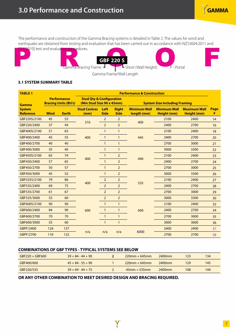
The performance and construction of the Gamma Bracing systems is detailed in Table 2. The values for wind and earthquake are obtained from testing and evaluation that has been carried out in accordance with NZS3604:2011 and P21[2010] test and evaluation procedures.
TABLE 1 Performance & Construction
Gamma System Reference
Performance Bracing Units (BU’s)
Stud Qty & Configuration (Min Stud Size 90 x 45mm) System Size Including Framing
Wind EarthStud Centres
(mm)Left Side
Right Side
Minimum Wall length (mm)
Minimum Wall Height (mm)
Maximum Wall Height (mm)
Page #
GBF220S/2100 45 53310
2 2400
2100 2400 14
GBF220/2400 37 44 2 2 2400 2700 16
GBF400S/2100 51 63
400
1 1
445
2100 2400 18
GBF400/2400 45 55 1 1 2400 2700 20
GBF400/2700 40 40 1 1 2700 3000 21
GBF400/3000 35 40
400
1 1
490
3000 3300 22
GBF450S/2100 65 74 1 2 2100 2400 23
GBF450/2400 57 65 1 2 2400 2700 24
GBF450/2700 50 57 1 2 2700 3000 25
GBF450/3000 45 52
400
1 2
535
3000 3300 26
GBF535S/2100 79 86 2 2 2100 2400 27
GBF535/2400 69 75 2 2 2400 2700 28
GBF535/2700 61 67 2 2 2700 3000 29
GBF535/3000 55 60
600
2 2
600
3000 3300 30
GBF600S/2100 90 90 1 1 2100 2400 32
GBF600/2400 84 90 1 1 2400 2700 34
GBF600/2700 70 70 1 1 2700 3000 35
GBF600/3000 55 60 1 1 3000 3600 36
GBPF/2400 124 137n/a n/a n/a 6000
2400 2400 37
GBPF/2700 110 122 2700 2700 38
GBF220 + GBF600 39 + 84 - 44 + 90 2 220mm + 645mm 2400mm 123 134
GBF400/600 45 + 84 - 55 + 90 1 220mm + 645mm 2400mm 129 145
GBF220/535 39 + 69 - 44 + 75 2 45mm + 535mm 2400mm 108 144
COMBINATIONS OF GBF TYPES - TYPICAL SYSTEMS SEE BELOW
OR ANY OTHER COMBINATION TO MEET DESIRED DESIGN AND BRACING REQUIRED.
3.1 SYSTEM SUMMARY TABLE
Short (Wall Height) P - Portal
Gamma Frame/Wall Length
Gamma Bracing Frame
GBF 220 S
γ TM
GAMMAγ TM
8
P R O O F
4.0 Gamma Bracing Software & Design Procedure
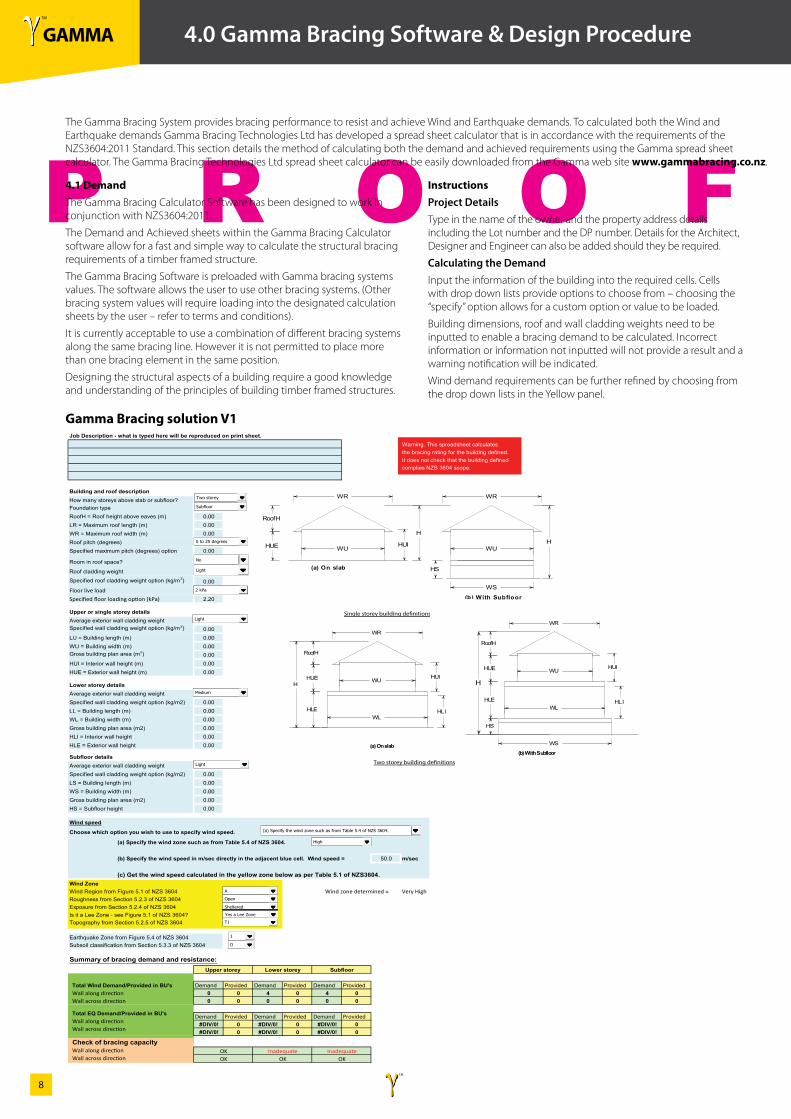
4.1 DemandThe Gamma Bracing Calculator Software has been designed to work in conjunction with NZS3604:2011.
The Demand and Achieved sheets within the Gamma Bracing Calculator software allow for a fast and simple way to calculate the structural bracing requirements of a timber framed structure.
The Gamma Bracing Software is preloaded with Gamma bracing systems values. The software allows the user to use other bracing systems. (Other bracing system values will require loading into the designated calculation sheets by the user – refer to terms and conditions).
It is currently acceptable to use a combination of different bracing systems along the same bracing line. However it is not permitted to place more than one bracing element in the same position.
Designing the structural aspects of a building require a good knowledge and understanding of the principles of building timber framed structures.
Gamma Bracing solution V1
InstructionsProject DetailsType in the name of the owner and the property address details including the Lot number and the DP number. Details for the Architect, Designer and Engineer can also be added should they be required.
Calculating the DemandInput the information of the building into the required cells. Cells with drop down lists provide options to choose from – choosing the “specify” option allows for a custom option or value to be loaded.
Building dimensions, roof and wall cladding weights need to be inputted to enable a bracing demand to be calculated. Incorrect information or information not inputted will not provide a result and a warning notification will be indicated.
Wind demand requirements can be further refined by choosing from the drop down lists in the Yellow panel.
36
11.0 Gamma Bracing Software Calculator - Demand
OVERVIEW
The Gamma Bracing Calculator Software has been designed to work in conjunction with NZS3604:2011.
The Demand and Achieved sheets within the Gamma Bracing Calculator software allow for a fast and simply way to calculate the structural bracing requirements of a timber framed structure.
The Gamma Bracing Software is preloaded with Gamma bracing systems values. The software allows the user to use other bracing systems. (Other bracing system values will require loading into the designated calculation sheets by the user – refer to terms and conditions).
It is currently acceptable to use a combination of different bracing systems along the same bracing line. However it is not permitted to place more than one bracing element in the same position.
Designing the structural aspects of a building require a good knowledge and understanding of the principles of building timber framed structures.
INSTRUCTIONS
Project Details Type in the name of the owner and the property address details including the Lot number and the DP number.
Details for the Architect, Designer and Engineer can be also be added should they be required.
Calculating the Demand Input the information of the building into the required cells. Cells with drop down lists provide options to choose from – choosing the “specify” option allows for a custom option or value to be loaded.
Building dimensions, roof and wall cladding weights need to be inputted to enable a bracing demand to be calculated. Incorrect information or information not inputted will not provide a result and a warning notification will be indicated.
Wind demand requirements can be further refined by choosing from the drop down lists in the Yellow panel.
Gamma bracing solution V1Job Description - what is typed here will be reproduced on print sheet.
Warning. This spreadsheet calculates the bracing rating for the building defined. It does not check that the building defined complies NZS 3604 scope.
Building and roof descriptionHow many storeys above slab or subfloor?Foundation typeRoofH = Roof height above eaves (m) 0.00
LR = Maximum roof length (m) 0.00WR = Maximum roof width (m) 0.00Roof pitch (degrees)
8Specified maximum pitch (degrees) option 0.00
Room in roof space?
Roof cladding weight
60Specified roof cladding weight option (kg/m2) 0.00
Floor live load
2.00Specified floor loading option (kPa) 2.20
Single storey building de�nitionsUpper or single storey detailsAverage exterior wall cladding weight
200Specified wall cladding weight option (kg/m2) 0.00LU = Building length (m) 0.00
WU = Building width (m) 0.00Gross building plan area (m2) 0.00HUI = Interior wall height (m) 0.00HUE = Exterior wall height (m) 0.00
Lower storey detailsAverage exterior wall cladding weight
200Specified wall cladding weight option (kg/m2) 0.00LL = Building length (m) 0.00
WL = Building width (m) 0.00
Gross building plan area (m2) 0.00HLI = Interior wall height 0.00HLE = Exterior wall height 0.00
Two storey building de�nitionsSubfloor detailsAverage exterior wall cladding weight
200Specified wall cladding weight option (kg/m2) 0.00LS = Building length (m) 0.00
WS = Building width (m) 0.00
Gross building plan area (m2) 0.00HS = Subfloor height 0.00 60
Wind speed
Choose which option you wish to use to specify wind speed.
(a) Specify the wind zone such as from Table 5.4 of NZS 3604.
(b) Specify the wind speed in m/sec directly in the adjacent blue cell. Wind speed = 50.0 m/sec
(c) Get the wind speed calculated in the yellow zone below as per Table 5.1 of NZS3604.Wind ZoneWind Region from Figure 5.1 of NZS 3604 Wind zone determined = Very HighRoughness from Section 5.2.3 of NZS 3604Exposure from Section 5.2.4 of NZS 3604Is it a Lee Zone - see Figure 5.1 of NZS 3604?Topography from Section 5.2.5 of NZS 3604
Earthquake Zone from Figure 5.4 of NZS 3604Subsoil classification from Section 5.3.3 of NZS 3604
Summary of bracing demand and resistance:
Total Wind Demand/Provided in BU's Demand Provided Demand Provided Demand ProvidedWall along direction 0 0 4 0 4 0Wall across direction 0 0 0 0 0 0
Total EQ Demand/Provided in BU's Demand Provided Demand Provided Demand ProvidedWall along direction #DIV/0! 0 #DIV/0! 0 #DIV/0! 0Wall across direction #DIV/0! 0 #DIV/0! 0 #DIV/0! 0
Check of bracing capacityWall along directionWall across direction
Upper storey Lower storey Subfloor
OK Inadequate InadequateOK OK OK
HUE
WR
WU
RoofH
HUI
H
WR
WU
HS
H
(a) On slab
(b) With Subfloor
WS
HUI
WL
(a) On slab
HUE
HLE
WR
WU
RoofH
H
HUIHUE
HLE
HS
H
WR
WU
WL
WS
RoofH
(b) With Subfloor
HL I
HL I
Two storey
Subfloor
0 to 25 degrees
Light
2 kPa
Light
A
Open
Sheltered
T1
Medium
Light
(a) Specify the wind zone such as from Table 5.4 of NZS 3604.
High
No
1
D
Yes a Lee Zone
The Gamma Bracing System provides bracing performance to resist and achieve Wind and Earthquake demands. To calculated both the Wind and Earthquake demands Gamma Bracing Technologies Ltd has developed a spread sheet calculator that is in accordance with the requirements of the NZS3604:2011 Standard. This section details the method of calculating both the demand and achieved requirements using the Gamma spread sheet calculator. The Gamma Bracing Technologies Ltd spread sheet calculator can be easily downloaded from the Gamma web site www.gammabracing.co.nz.
γ TM
GAMMAγ TM
9
P R O O F
4.2 Gamma Bracing Software - Achieved
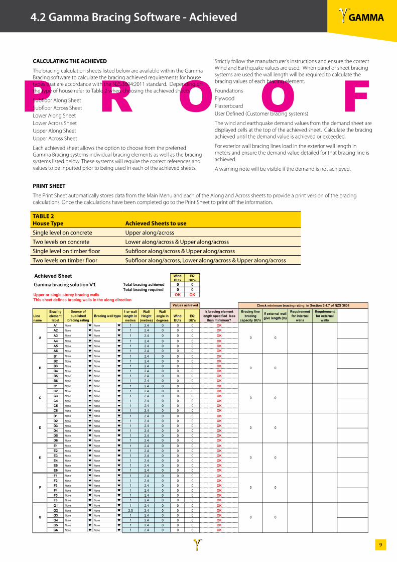
CALCULATING THE ACHIEVED
The bracing calculation sheets listed below are available within the Gamma Bracing software to calculate the bracing achieved requirements for house types that are accordance with the NZS3604:2011 standard. Depending on the type of house refer to Table 2 when choosing the achieved sheets
Subfloor Along SheetSubfloor Across SheetLower Along SheetLower Across SheetUpper Along SheetUpper Across Sheet
Each achieved sheet allows the option to choose from the preferred Gamma Bracing systems individual bracing elements as well as the bracing systems listed below. These systems will require the correct references and values to be inputted prior to being used in each of the achieved sheets.
PRINT SHEET
The Print Sheet automatically stores data from the Main Menu and each of the Along and Across sheets to provide a print version of the bracing calculations. Once the calculations have been completed go to the Print Sheet to print off the information.
Strictly follow the manufacturer’s instructions and ensure the correct Wind and Earthquake values are used. When panel or sheet bracing systems are used the wall length will be required to calculate the bracing values of each bracing element.
FoundationsPlywoodPlasterboardUser Defined (Customer bracing systems)
The wind and earthquake demand values from the demand sheet are displayed cells at the top of the achieved sheet. Calculate the bracing achieved until the demand value is achieved or exceeded.
For exterior wall bracing lines load in the exterior wall length in meters and ensure the demand value detailed for that bracing line is achieved.
A warning note will be visible if the demand is not achieved.
37
11.1 Gamma Bracing Software - Achieved
CALCULATING THE ACHIEVED
The bracing calculation sheets listed below are available within the Gamma Bracing software to calculate the bracing achieved requirements for house types that are accordance with the NZS3604:2011 standard. Depending on the type of house refer to Table 1 when choosing the achieved sheets
Subfloor Along Sheet
Subfloor Across Sheet
Lower Along Sheet
Lower Across Sheet
Upper Along Sheet
Upper Across Sheet
Each achieved sheet allows the option to choose from the preferred Gamma Bracing systems individual bracing elements as well as the bracing systems listed below. These systems will require the correct references and values to be inputted prior to being used in each of the achieved sheets.
Strictly follow the manufacturer’s instructions and ensure the correct Wind and Earthquake values are used. When panel or sheet bracing systems are used the wall length will be required to calculate the bracing values of each bracing element.
Foundations
Plywood
Plasterboard
User Defined (Custom bracing systems)
The wind and earthquake demand values from the demand sheet are displayed cells at the top of the achieved sheet. Calculated the bracing achieved until the demand value is achieved or exceeded.
For exterior wall bracing lines load in the exterior wall length in meters and ensure the demand value detailed for that bracing line is achieved.
A warning note will be visible if the demand is not achieved.
Wind BU's
EQ BU's
Total bracing achieved 0 0Total bracing required 0 0
Upper or single storey bracing walls OK OKThis sheet defines bracing walls in the along direction
Line name
Bracing element
label
Source of published
bracing ratingBracing wall type
1 or wall length in metres
Wall Height
(metres)
Wall angle in degrees
Wind BU's
EQ BU's
Is bracing element length specified less
than minimum?
Bracing line bracing
capacity BU's
If external wall give length (m)
Requirement for internal
walls
Requirement for external
wallsA1 1 2.4 0 0 0 OKA2 1 2.4 0 0 0 OKA3 1 2.4 0 0 0 OKA4 1 2.4 0 0 0 OKA5 1 2.4 0 0 0 OKA6 1 2.4 0 0 0 OKB1 1 2.4 0 0 0 OKB2 1 2.4 0 0 0 OKB3 1 2.4 0 0 0 OKB4 1 2.4 0 0 0 OKB5 1 2.4 0 0 0 OKB6 1 2.4 0 0 0 OKC1 1 2.4 0 0 0 OKC2 1 2.4 0 0 0 OKC3 1 2.4 0 0 0 OKC4 1 2.4 0 0 0 OKC5 1 2.4 0 0 0 OKC6 1 2.4 0 0 0 OKD1 1 2.4 0 0 0 OKD2 1 2.4 0 0 0 OKD3 1 2.4 0 0 0 OKD4 1 2.4 0 0 0 OKD5 1 2.4 0 0 0 OKD6 1 2.4 0 0 0 OKE1 1 2.4 0 0 0 OKE2 1 2.4 0 0 0 OKE3 1 2.4 0 0 0 OKE4 1 2.4 0 0 0 OKE5 1 2.4 0 0 0 OKE6 1 2.4 0 0 0 OKF1 1 2.4 0 0 0 OKF2 1 2.4 0 0 0 OKF3 1 2.4 0 0 0 OKF4 1 2.4 0 0 0 OKF5 1 2.4 0 0 0 OKF6 1 2.4 0 0 0 OKG1 1 2.4 0 0 0 OKG2 2.5 2.4 0 0 0 OKG3 1 2.4 0 0 0 OKG4 1 2.4 0 0 0 OKG5 1 2.4 0 0 0 OKG6 1 2.4 0 0 0 OK
Values achieved Check minimum bracing rating in Section 5.4.7 of NZS 3604
A 0 0
B 0 0
C 0 0
D 0 0
E 0 0
F 0 0
G 0 0
None None
None
None
None
None
None
None
None
None
None
None
None
None
None
None
None
None
None
None
None
None
None
None
None
None
None
None
None
None
None
None
None
None
None
None
None
None
None
None
None
None
None
None
None
None
None
None
None
None
None
None
None
None
None
None
None
None
None
None
None
None
None
None
None
None
None
None
None
None
None
None
None
None
None
None
None
None
None
None
None
None
None
None
Calculating the Achieved The bracing calculation sheets listed below are available within the Gamma Bracing software to calculate the bracing achieved requirements for house types that are accordance with the NZS3604:2011 standard. Depending on the type of house refer to Table 1 when choosing the achieved sheets Subfloor Along Sheet Subfloor Across Sheet Lower Along Sheet Lower Across Sheet Upper Along Sheet Upper Across Sheet
Each achieved sheet allows the option to choose from the preferred Gamma Bracing systems individual bracing elements as well as the bracing systems listed below. These systems will require the correct references and values to be inputted prior to being used in each of the achieved sheets.
Strictly follow the manufacturer’s instructions and ensure the correct Wind and Earthquake values are used. When panel or sheet bracing systems are used the wall length will be required to calculate the bracing values of each bracing element. Foundations Plywood Plasterboard User Defined (Custom bracing systems)
The wind and earthquake demand values from the demand sheet are displayed cells at the top of the achieved sheet. Calculated the bracing achieved until the demand value is achieved or exceeded. For exterior wall bracing lines load in the exterior wall length in meters and ensure the demand value detailed for that bracing line is achieved. A warning note will be visible if the demand is not achieved. Print Sheet The Print Sheet automatically stores data from the Main Menu and each of the Along and Across sheets to provide a print version of the bracing calculations. Once the calculations have been completed go to the Print Sheet to print off the information.
House Type Achieved Sheets to use Single level on concrete Upper along/across Two levels on concrete Lower along/across & Upper along/across Single level on timber floor Subfloor along/across & Upper along/across Two level on timber floor Subfloor along/across, Lower along/across & Upper along/across
11.1 Gamma Bracing Software - Achieved
Achieved Sheet
PRINT SHEET
The Print Sheet automatically stores data from the Main Menu and each of the Along and Across sheets to provide a print version of the bracing calculations. Once the calculations have been completed go to the Print Sheet to print off the information.
Gamma bracing solution V1
TABLE 1
TABLE 2 House Type
Achieved Sheets to use
Single level on concrete Upper along/across
Two levels on concrete Lower along/across & Upper along/across
Single level on timber floor Subfloor along/across & Upper along/across
Two levels on timber floor Subfloor along/across, Lower along/across & Upper along/across
γ TM
GAMMAγ TM
10
P R O O F
5.0 Installation Procedure
TABLE 3GAMMA INSTALLATION PROCEDURE
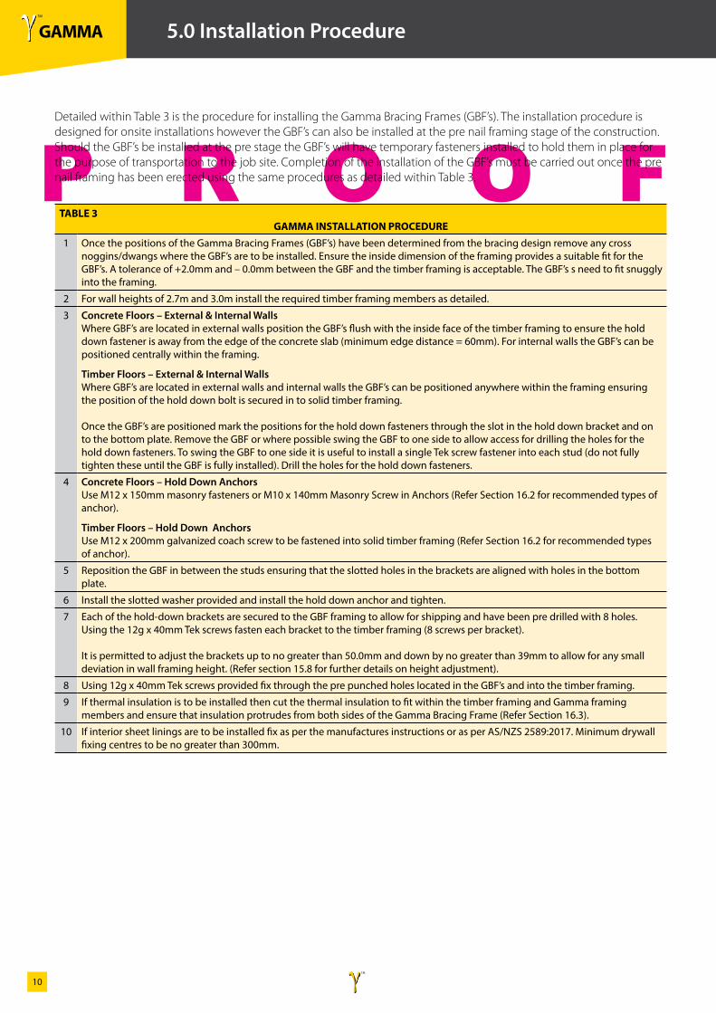
1 Once the positions of the Gamma Bracing Frames (GBF’s) have been determined from the bracing design remove any cross noggins/dwangs where the GBF’s are to be installed. Ensure the inside dimension of the framing provides a suitable fit for the GBF’s. A tolerance of +2.0mm and – 0.0mm between the GBF and the timber framing is acceptable. The GBF’s s need to fit snuggly into the framing.
2 For wall heights of 2.7m and 3.0m install the required timber framing members as detailed.
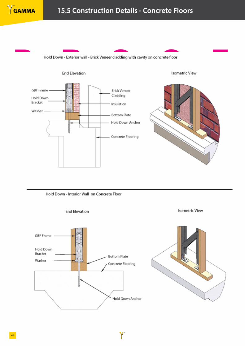
3 Concrete Floors – External & Internal WallsWhere GBF’s are located in external walls position the GBF’s flush with the inside face of the timber framing to ensure the hold down fastener is away from the edge of the concrete slab (minimum edge distance = 60mm). For internal walls the GBF’s can be positioned centrally within the framing.
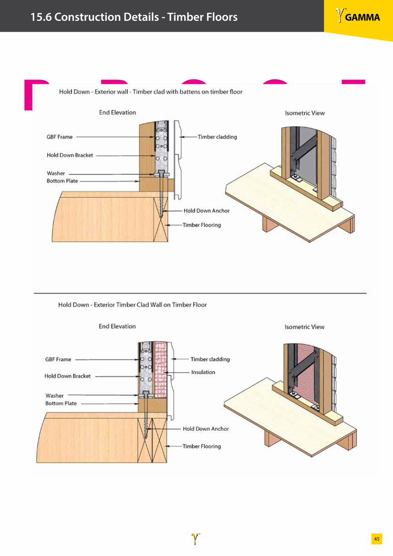
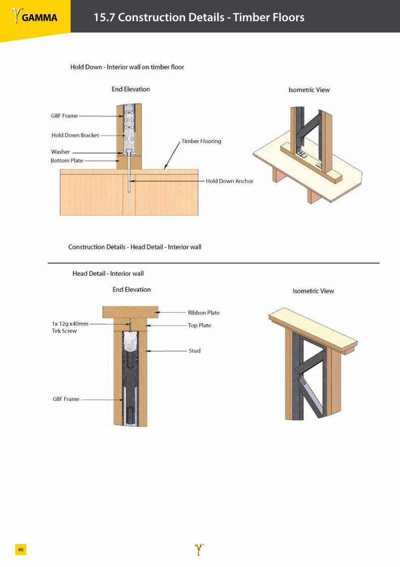
Timber Floors – External & Internal WallsWhere GBF’s are located in external walls and internal walls the GBF’s can be positioned anywhere within the framing ensuring the position of the hold down bolt is secured in to solid timber framing.
Once the GBF’s are positioned mark the positions for the hold down fasteners through the slot in the hold down bracket and on to the bottom plate. Remove the GBF or where possible swing the GBF to one side to allow access for drilling the holes for the hold down fasteners. To swing the GBF to one side it is useful to install a single Tek screw fastener into each stud (do not fully tighten these until the GBF is fully installed). Drill the holes for the hold down fasteners.
4 Concrete Floors – Hold Down AnchorsUse M12 x 150mm masonry fasteners or M10 x 140mm Masonry Screw in Anchors (Refer Section 16.2 for recommended types of anchor).
Timber Floors – Hold Down AnchorsUse M12 x 200mm galvanized coach screw to be fastened into solid timber framing (Refer Section 16.2 for recommended types of anchor).
5 Reposition the GBF in between the studs ensuring that the slotted holes in the brackets are aligned with holes in the bottom plate.
6 Install the slotted washer provided and install the hold down anchor and tighten.
7 Each of the hold-down brackets are secured to the GBF framing to allow for shipping and have been pre drilled with 8 holes. Using the 12g x 40mm Tek screws fasten each bracket to the timber framing (8 screws per bracket).
It is permitted to adjust the brackets up to no greater than 50.0mm and down by no greater than 39mm to allow for any small deviation in wall framing height. (Refer section 15.8 for further details on height adjustment).
8 Using 12g x 40mm Tek screws provided fix through the pre punched holes located in the GBF’s and into the timber framing.
9 If thermal insulation is to be installed then cut the thermal insulation to fit within the timber framing and Gamma framing members and ensure that insulation protrudes from both sides of the Gamma Bracing Frame (Refer Section 16.3).
10 If interior sheet linings are to be installed fix as per the manufactures instructions or as per AS/NZS 2589:2017. Minimum drywall fixing centres to be no greater than 300mm.
Detailed within Table 3 is the procedure for installing the Gamma Bracing Frames (GBF’s). The installation procedure is designed for onsite installations however the GBF’s can also be installed at the pre nail framing stage of the construction. Should the GBF’s be installed at the pre stage the GBF’s will have temporary fasteners installed to hold them in place for the purpose of transportation to the job site. Completion of the installation of the GBF’s must be carried out once the pre nail framing has been erected using the same procedures as detailed within Table 3.
γ TM
GAMMAγ TM
11
P R O O F
5.0 Installation Procedure
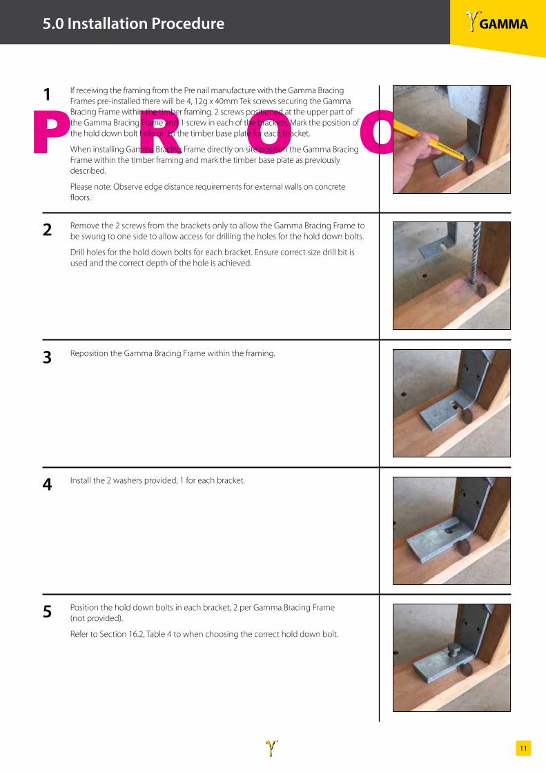
If receiving the framing from the Pre nail manufacture with the Gamma Bracing Frames pre-installed there will be 4, 12g x 40mm Tek screws securing the Gamma Bracing Frame within the timber framing. 2 screws positioned at the upper part of the Gamma Bracing Frame and 1 screw in each of the brackets. Mark the position of the hold down bolt hole on to the timber base plate for each bracket.
When installing Gamma Bracing Frame directly on site position the Gamma Bracing Frame within the timber framing and mark the timber base plate as previously described.
Please note: Observe edge distance requirements for external walls on concrete floors.
Remove the 2 screws from the brackets only to allow the Gamma Bracing Frame to be swung to one side to allow access for drilling the holes for the hold down bolts.
Drill holes for the hold down bolts for each bracket. Ensure correct size drill bit is used and the correct depth of the hole is achieved.
Reposition the Gamma Bracing Frame within the framing.
Install the 2 washers provided, 1 for each bracket.
Position the hold down bolts in each bracket, 2 per Gamma Bracing Frame (not provided).
Refer to Section 16.2, Table 4 to when choosing the correct hold down bolt.
1
2
3
4
5
γ TM
GAMMAγ TM
12
P R O O F
5.0 Installation Procedure
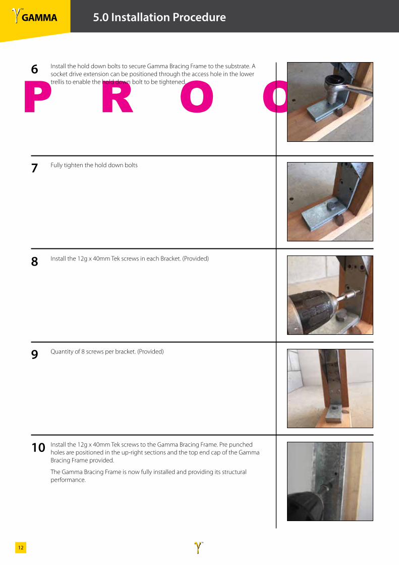
Install the hold down bolts to secure Gamma Bracing Frame to the substrate. A socket drive extension can be positioned through the access hole in the lower trellis to enable the hold down bolt to be tightened.
Fully tighten the hold down bolts
Install the 12g x 40mm Tek screws in each Bracket. (Provided)
Quantity of 8 screws per bracket. (Provided)
Install the 12g x 40mm Tek screws to the Gamma Bracing Frame. Pre punched holes are positioned in the up-right sections and the top end cap of the Gamma Bracing Frame provided.
The Gamma Bracing Frame is now fully installed and providing its structural performance.
6
7
8
9
10
γ TM
GAMMAγ TM
13
P R O O F
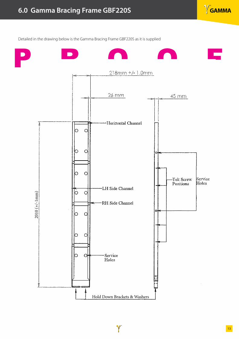
6.0 Gamma Bracing Frame GBF220S
2010
(+/-
1mm
)
Hold Down Brackets & Washers
Detailed in the drawing below is the Gamma Bracing Frame GBF220S as it is supplied
γ TM
GAMMAγ TM
14
P R O O F
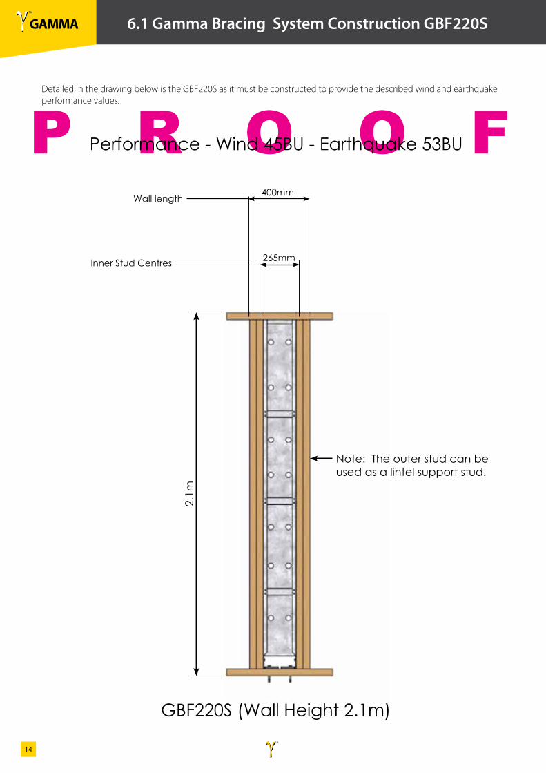
6.1 Gamma Bracing System Construction GBF220S
Performance - Wind 45BU - Earthquake 53BU
Note: The outer stud can be used as a lintel support stud.
Detailed in the drawing below is the GBF220S as it must be constructed to provide the described wind and earthquake performance values.
GBF220S (Wall Height 2.1m)
2.1m
Inner Stud Centres
400mm
265mm
Wall length
γ TM
GAMMAγ TM
15
P R O O F
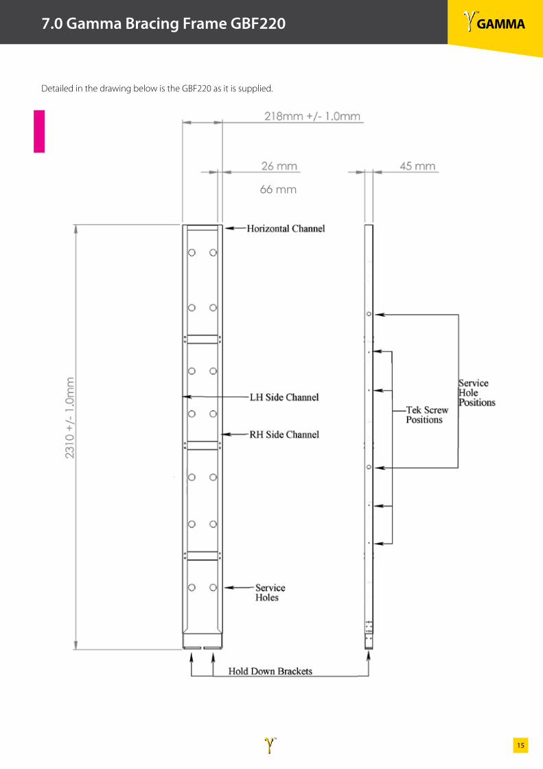
7.0 Gamma Bracing Frame GBF220
66 mm
Detailed in the drawing below is the GBF220 as it is supplied.
γ TM
GAMMAγ TM
16
P R O O F
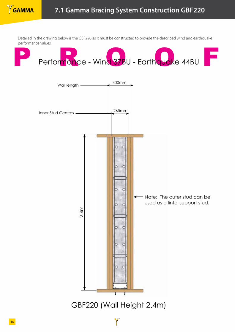
7.1 Gamma Bracing System Construction GBF220
Performance - Wind 37BU - Earthquake 44BU
Note: The outer stud can be used as a lintel support stud.
GBF220 (Wall Height 2.4m)
2.4m
Detailed in the drawing below is the GBF220 as it must be constructed to provide the described wind and earthquake performance values.
Inner Stud Centres
400mm
265mm
Wall length

γ TM
GAMMAγ TM
17
P R O O F
8.0 Gamma Bracing Frame GBF400S
Detailed in the drawing below is the GBF400S as it is supplied.
2010
(+/-
1.0
mm
)
γ TM
GAMMAγ TM
18
P R O O F
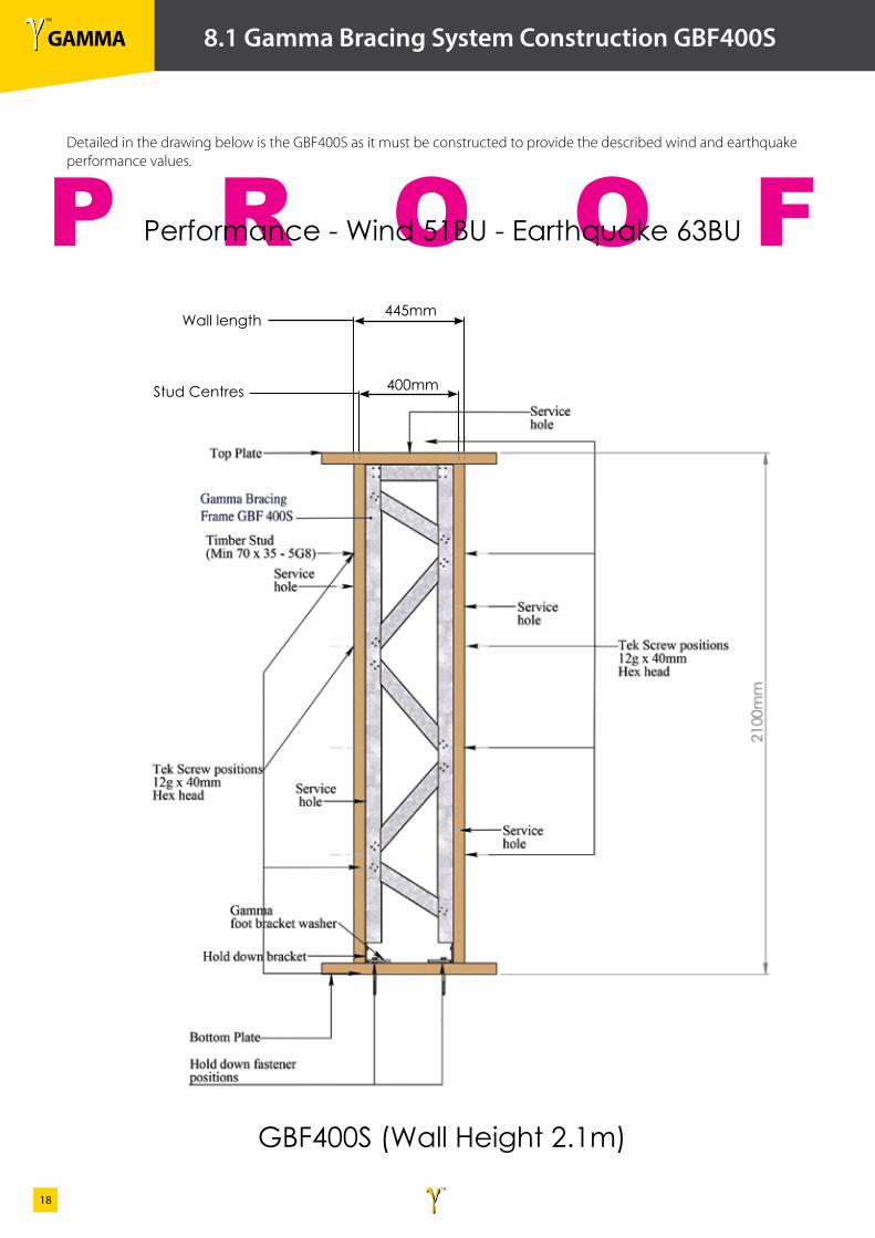
8.1 Gamma Bracing System Construction GBF400S
Detailed in the drawing below is the GBF400S as it must be constructed to provide the described wind and earthquake performance values.
Performance - Wind 51BU - Earthquake 63BU
GBF400S (Wall Height 2.1m)
Stud Centres
445mm
400mm
Wall length
γ TM
GAMMAγ TM
19
P R O O F
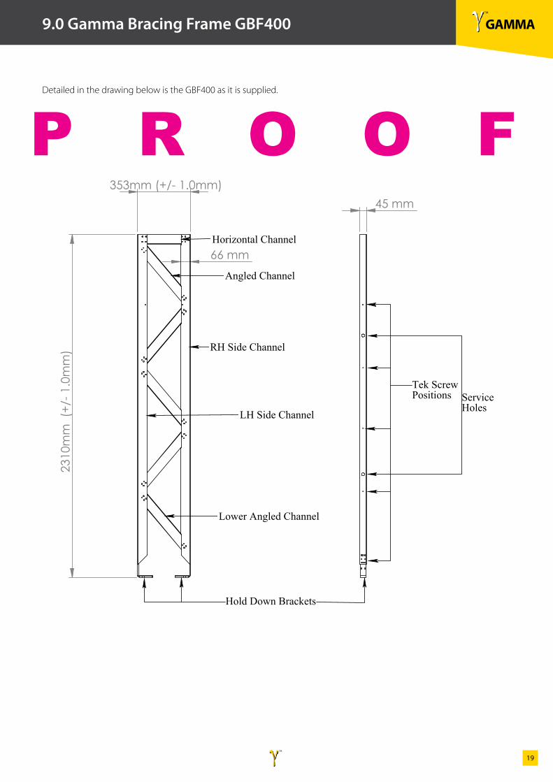
9.0 Gamma Bracing Frame GBF400
231
0mm
(+/
- 1.0
mm
)
353mm (+/- 1.0mm)
66 mm
LH Side Channel
RH Side Channel
Horizontal Channel
Angled Channel
Lower Angled Channel
45 mm
Hold Down Brackets
Tek Screw Positions Service
Holes
Gamma Bracing Frame GBF 400Detailed in the drawing below is the GBF400 as it is supplied.
γ TM
GAMMAγ TM
20
P R O O F
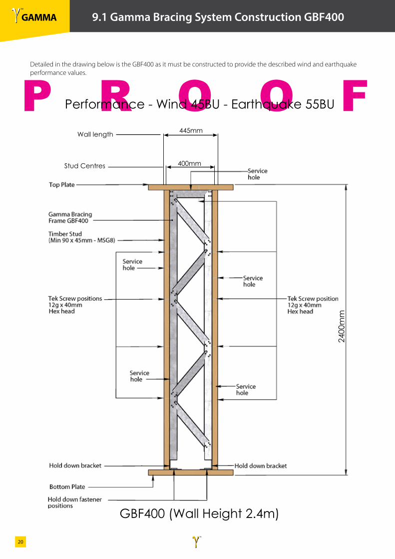
9.1 Gamma Bracing System Construction GBF400
Detailed in the drawing below is the GBF400 as it must be constructed to provide the described wind and earthquake performance values.
Performance - Wind 45BU - Earthquake 55BU
GBF400 (Wall Height 2.4m)
445mm
2400
mm
400mmStud Centres
Wall length
γ TM
GAMMAγ TM
21
P R O O F
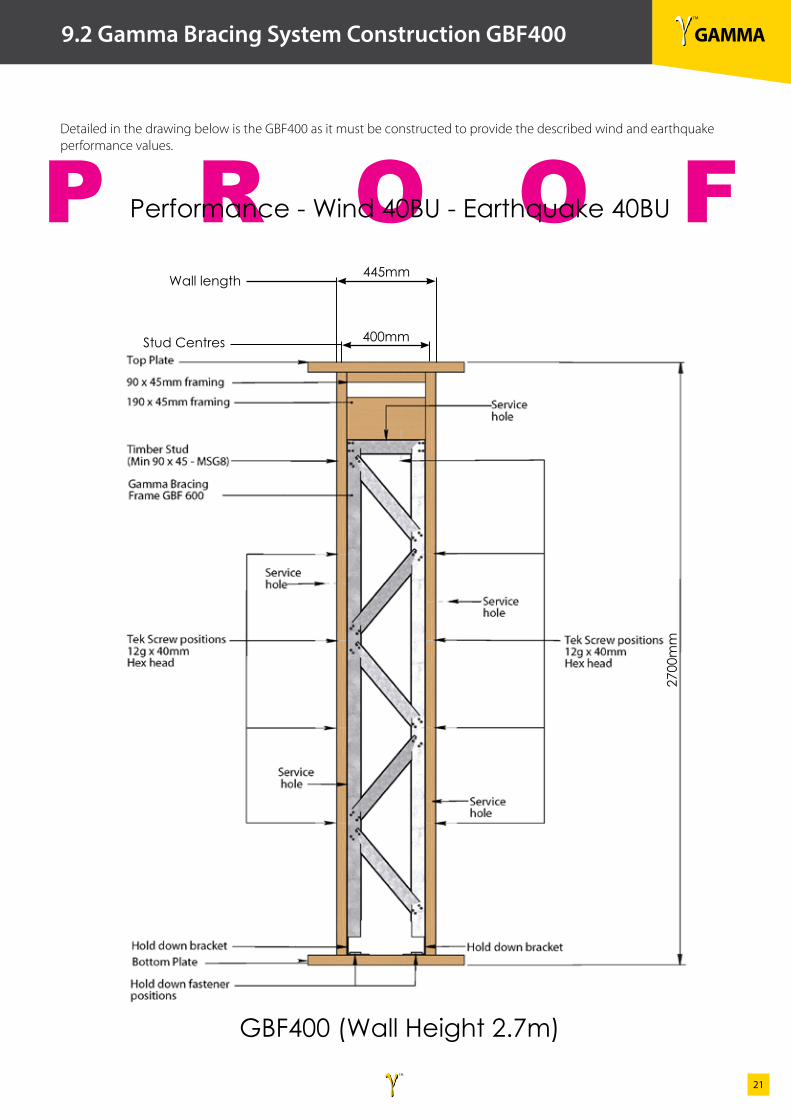
9.2 Gamma Bracing System Construction GBF400
Detailed in the drawing below is the GBF400 as it must be constructed to provide the described wind and earthquake performance values.
Performance - Wind 40BU - Earthquake 40BU
GBF400 (Wall Height 2.7m)
445mm
2700
mm
400mmStud Centres
Wall length
γ TM
GAMMAγ TM
22
P R O O F
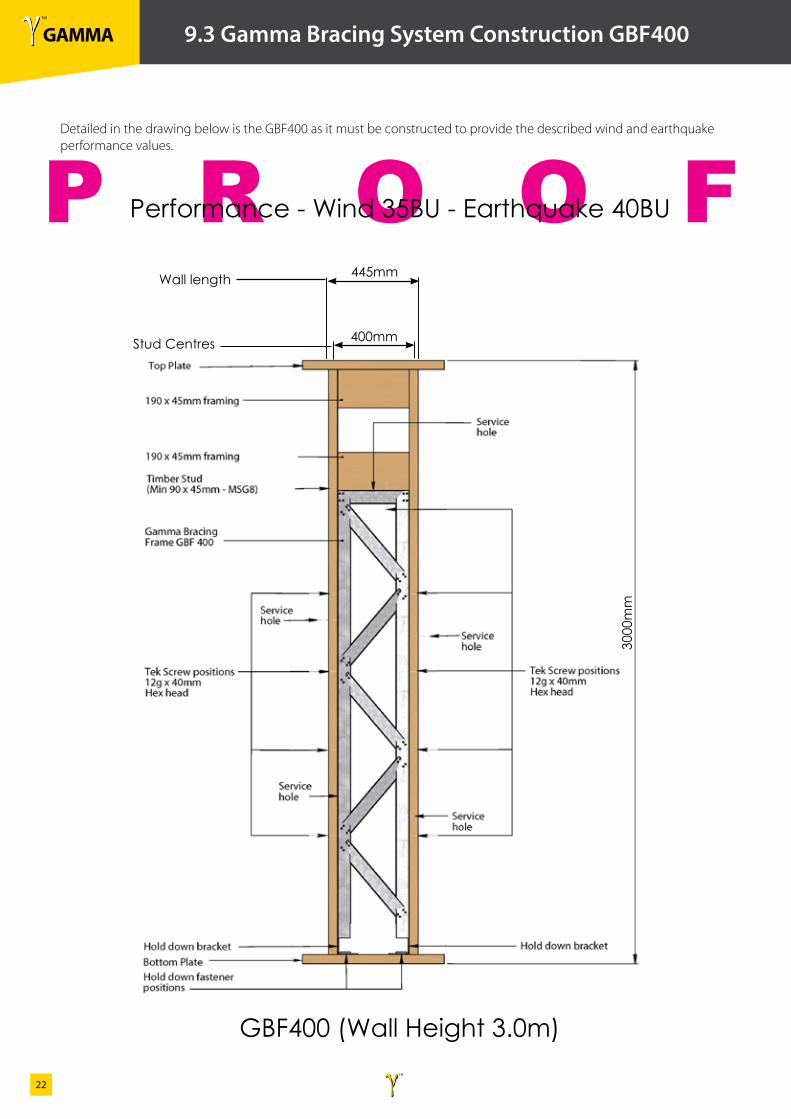
9.3 Gamma Bracing System Construction GBF400
Detailed in the drawing below is the GBF400 as it must be constructed to provide the described wind and earthquake performance values.
Performance - Wind 35BU - Earthquake 40BU
GBF400 (Wall Height 3.0m)
445mm
3000
mm
400mmStud Centres
Wall length
γ TM
GAMMAγ TM
23
P R O O F
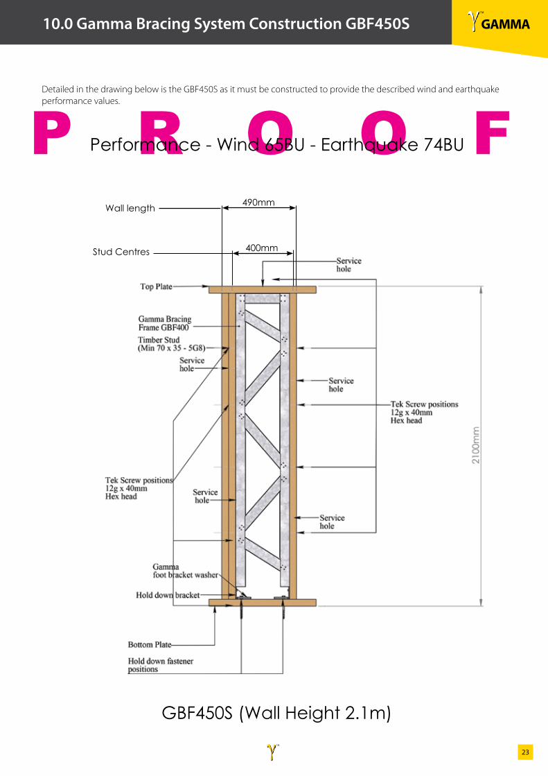
10.0 Gamma Bracing System Construction GBF450S
Detailed in the drawing below is the GBF450S as it must be constructed to provide the described wind and earthquake performance values.
Performance - Wind 65BU - Earthquake 74BU
GBF450S (Wall Height 2.1m)
490mm
400mmStud Centres
Wall length
γ TM
GAMMAγ TM
24
P R O O F
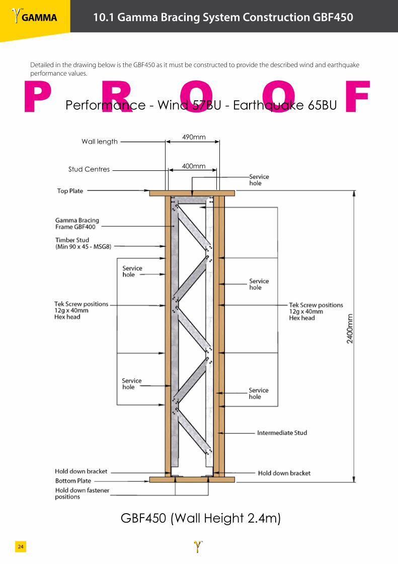
10.1 Gamma Bracing System Construction GBF450
Detailed in the drawing below is the GBF450 as it must be constructed to provide the described wind and earthquake performance values.
Performance - Wind 57BU - Earthquake 65BU
GBF450 (Wall Height 2.4m)
490mm
400mmStud Centres
Wall length
γ TM
GAMMAγ TM
25
P R O O F
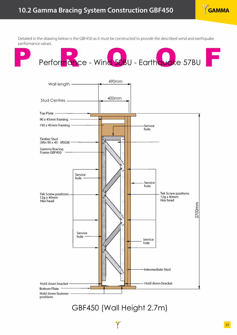
10.2 Gamma Bracing System Construction GBF450
Detailed in the drawing below is the GBF450 as it must be constructed to provide the described wind and earthquake performance values.
Performance - Wind 50BU - Earthquake 57BU
GBF450 (Wall Height 2.7m)
490mm
400mmStud Centres
Wall length
γ TM
GAMMAγ TM
26
P R O O F
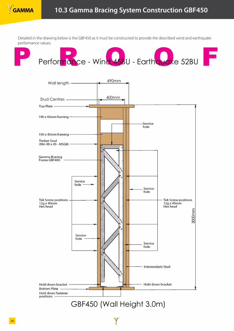
10.3 Gamma Bracing System Construction GBF450
Detailed in the drawing below is the GBF450 as it must be constructed to provide the described wind and earthquake performance values.
Performance - Wind 45BU - Earthquake 52BU
GBF450 (Wall Height 3.0m)
490mm
400mmStud Centres
Wall length
γ TM
GAMMAγ TM
27
P R O O F
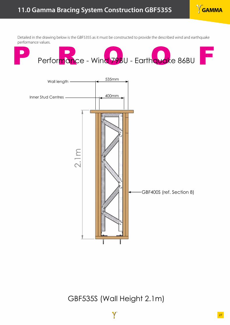
11.0 Gamma Bracing System Construction GBF535S
Detailed in the drawing below is the GBF535S as it must be constructed to provide the described wind and earthquake performance values.
Performance - Wind 79BU - Earthquake 86BU
GBF535S (Wall Height 2.1m)
535mm
GBF400S (ref. Section 8)
400mmInner Stud Centres
Wall length
γ TM
GAMMAγ TM
28
P R O O F
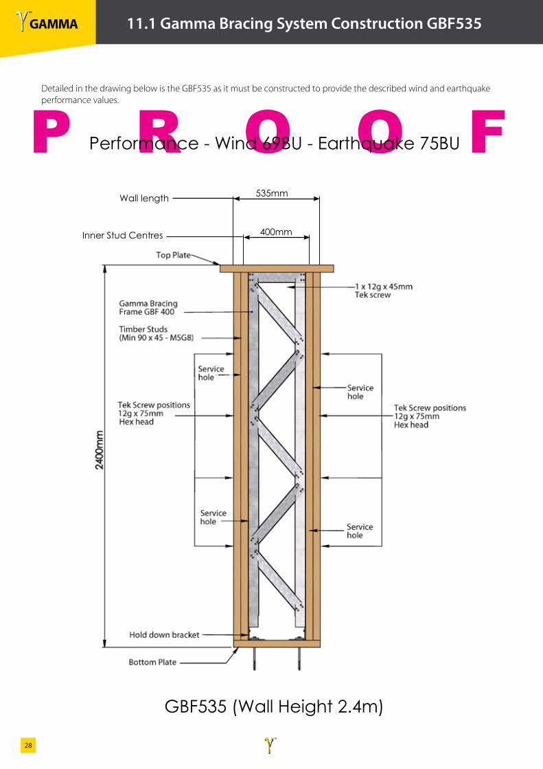
11.1 Gamma Bracing System Construction GBF535
Detailed in the drawing below is the GBF535 as it must be constructed to provide the described wind and earthquake performance values.
Performance - Wind 69BU - Earthquake 75BU
GBF535 (Wall Height 2.4m)
535mm
400mmInner Stud Centres
Wall length
γ TM
GAMMAγ TM
29
P R O O F
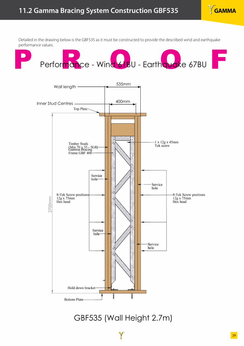
11.2 Gamma Bracing System Construction GBF535
Detailed in the drawing below is the GBF535 as it must be constructed to provide the described wind and earthquake performance values.
Performance - Wind 61BU - Earthquake 67BU
GBF535 (Wall Height 2.7m)
535mm
400mmInner Stud Centres
Wall length
γ TM
GAMMAγ TM
30
P R O O F
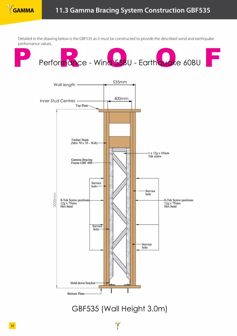
11.3 Gamma Bracing System Construction GBF535
Detailed in the drawing below is the GBF535 as it must be constructed to provide the described wind and earthquake performance values.
Performance - Wind 55BU - Earthquake 60BU
GBF535 (Wall Height 3.0m)
535mm
400mmInner Stud Centres
Wall length
γ TM
GAMMAγ TM
31
P R O O F
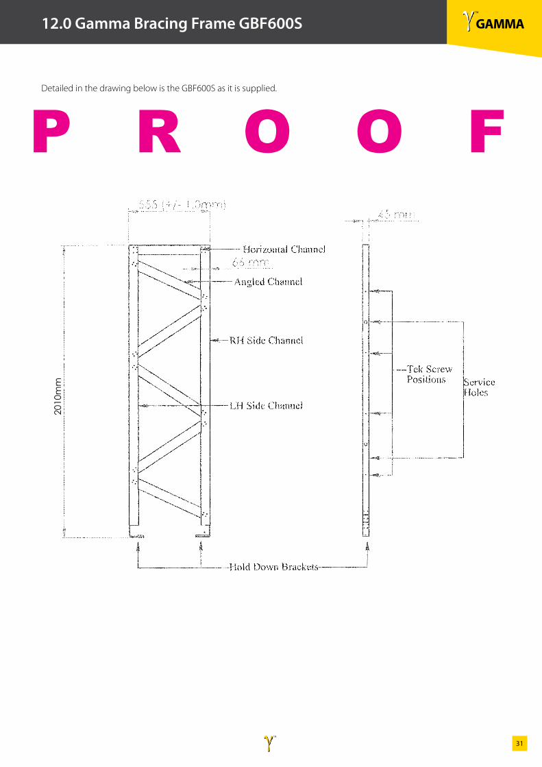
12.0 Gamma Bracing Frame GBF600S
Detailed in the drawing below is the GBF600S as it is supplied.
2010
mm
γ TM
GAMMAγ TM
32
P R O O F
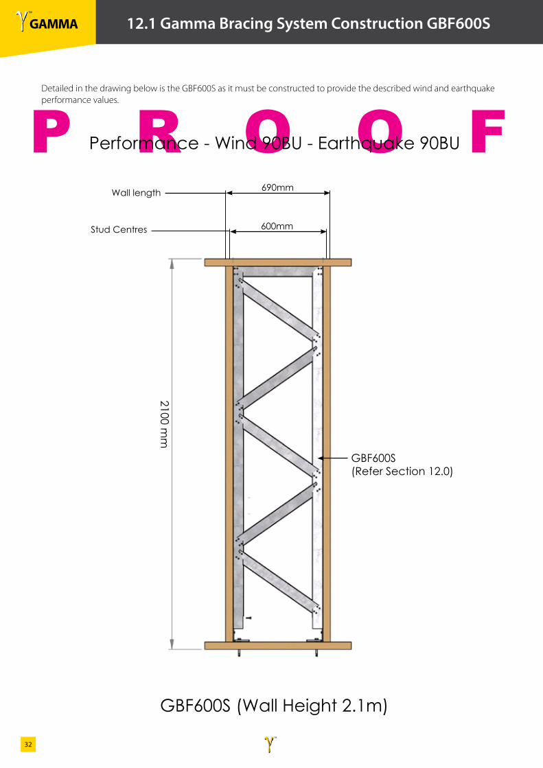
12.1 Gamma Bracing System Construction GBF600S
2100 mm
Detailed in the drawing below is the GBF600S as it must be constructed to provide the described wind and earthquake performance values.
Performance - Wind 90BU - Earthquake 90BU
GBF600S (Wall Height 2.1m)
690mm
GBF600S (Refer Section 12.0)
600mmStud Centres
Wall length

γ TM
GAMMAγ TM
33
P R O O F 2
310m
m (
+/- 1
.0m
m)
553mm (+/- 1.0mm)
66 mm
LH Side Channel
RH Side Channel
Horizontal Channel
Angled Channel
45 mm
Hold Down Brackets
Tek Screw Positions Service
Holes
Gamma Bracing Frame GBF 600
13.0 Gamma Bracing Frame GBF600
Detailed in the drawing below is the GBF600 as it is supplied.
γ TM
GAMMAγ TM
34
P R O O F
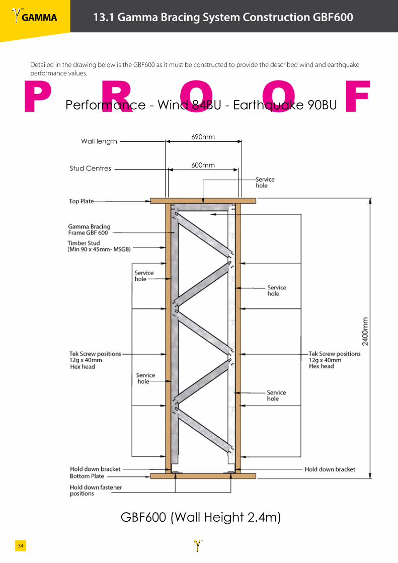
13.1 Gamma Bracing System Construction GBF600
Detailed in the drawing below is the GBF600 as it must be constructed to provide the described wind and earthquake performance values.
Performance - Wind 84BU - Earthquake 90BU
GBF600 (Wall Height 2.4m)
600mm
690mm
Stud Centres
Wall length
γ TM
GAMMAγ TM
35
P R O O F
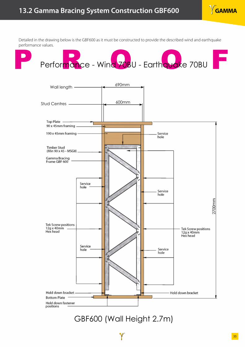
13.2 Gamma Bracing System Construction GBF600
Detailed in the drawing below is the GBF600 as it must be constructed to provide the described wind and earthquake performance values.
Performance - Wind 70BU - Earthquake 70BU
GBF600 (Wall Height 2.7m)
690mm
600mmStud Centres
Wall length
γ TM
GAMMAγ TM
36
P R O O F
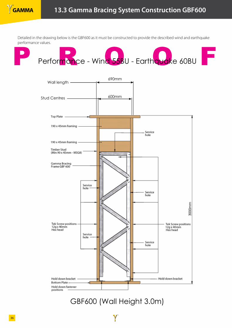
13.3 Gamma Bracing System Construction GBF600
Detailed in the drawing below is the GBF600 as it must be constructed to provide the described wind and earthquake performance values.
Performance - Wind 55BU - Earthquake 60BU
GBF600 (Wall Height 3.0m)
690mm
600mmStud Centres
Wall length
γ TM
GAMMAγ TM
37
P R O O F
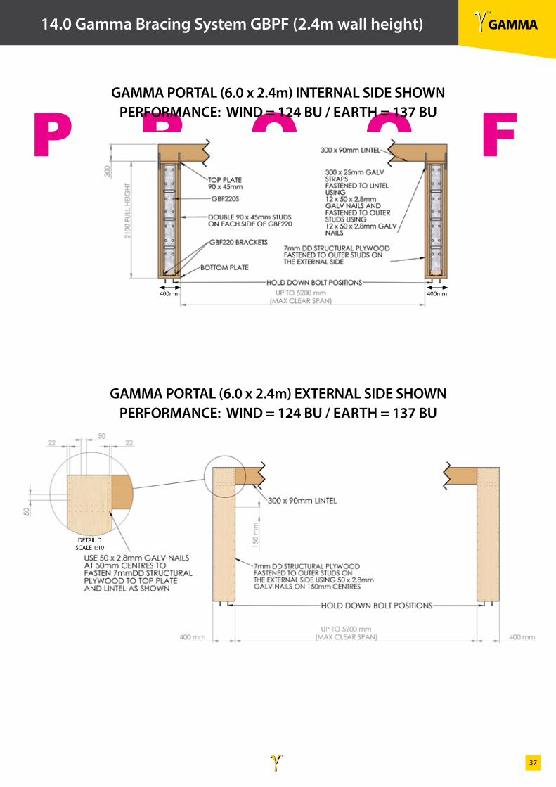
14.0 Gamma Bracing System GBPF (2.4m wall height)
GAMMA PORTAL (6.0 x 2.4m) INTERNAL SIDE SHOWNPERFORMANCE: WIND = 124 BU / EARTH = 137 BU
GAMMA PORTAL (6.0 x 2.4m) EXTERNAL SIDE SHOWNPERFORMANCE: WIND = 124 BU / EARTH = 137 BU
400mm400mm
DETAIL D SCALE 1:10
γ TM
GAMMAγ TM
38
P R O O F
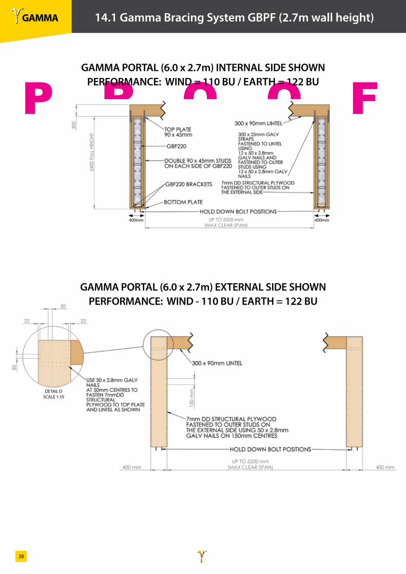
14.1 Gamma Bracing System GBPF (2.7m wall height)
GAMMA PORTAL (6.0 x 2.7m) INTERNAL SIDE SHOWNPERFORMANCE: WIND = 110 BU / EARTH = 122 BU
GAMMA PORTAL (6.0 x 2.7m) EXTERNAL SIDE SHOWNPERFORMANCE: WIND - 110 BU / EARTH = 122 BU
400mm400mm
DETAIL D SCALE 1:10
γ TM
GAMMAγ TM
39
P R O O F
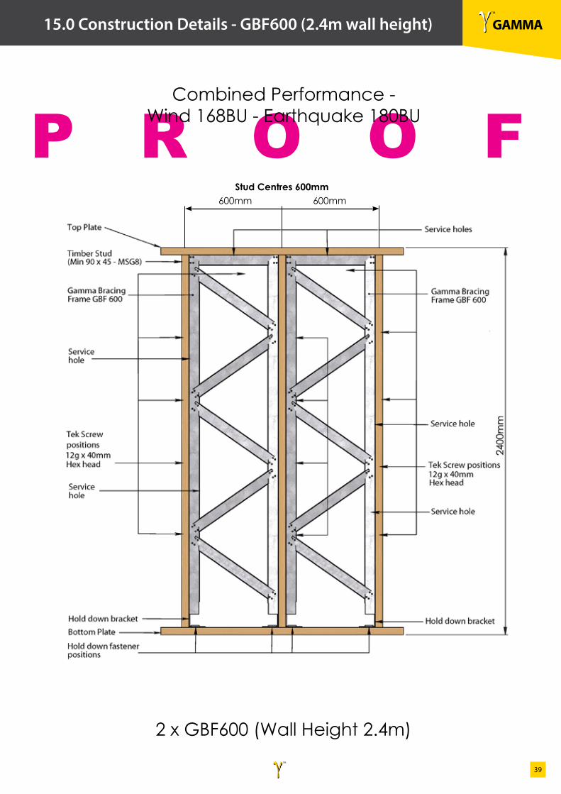
15.0 Construction Details - GBF600 (2.4m wall height)
Combined Performance - Wind 168BU - Earthquake 180BU
2 x GBF600 (Wall Height 2.4m)
Stud Centres 600mm600mm 600mm
γ TM
GAMMAγ TM
40
P R O O F
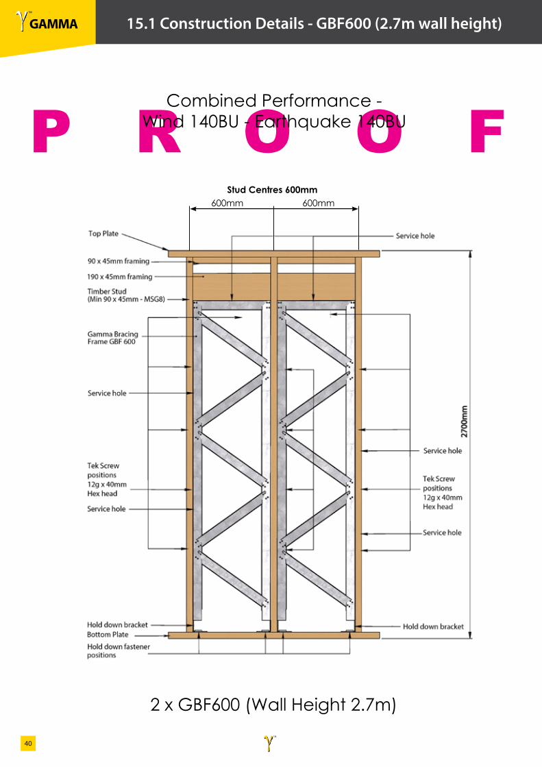
15.1 Construction Details - GBF600 (2.7m wall height)
Combined Performance - Wind 140BU - Earthquake 140BU
2 x GBF600 (Wall Height 2.7m)
Stud Centres 600mm600mm 600mm
γ TM
GAMMAγ TM
41
P R O O F
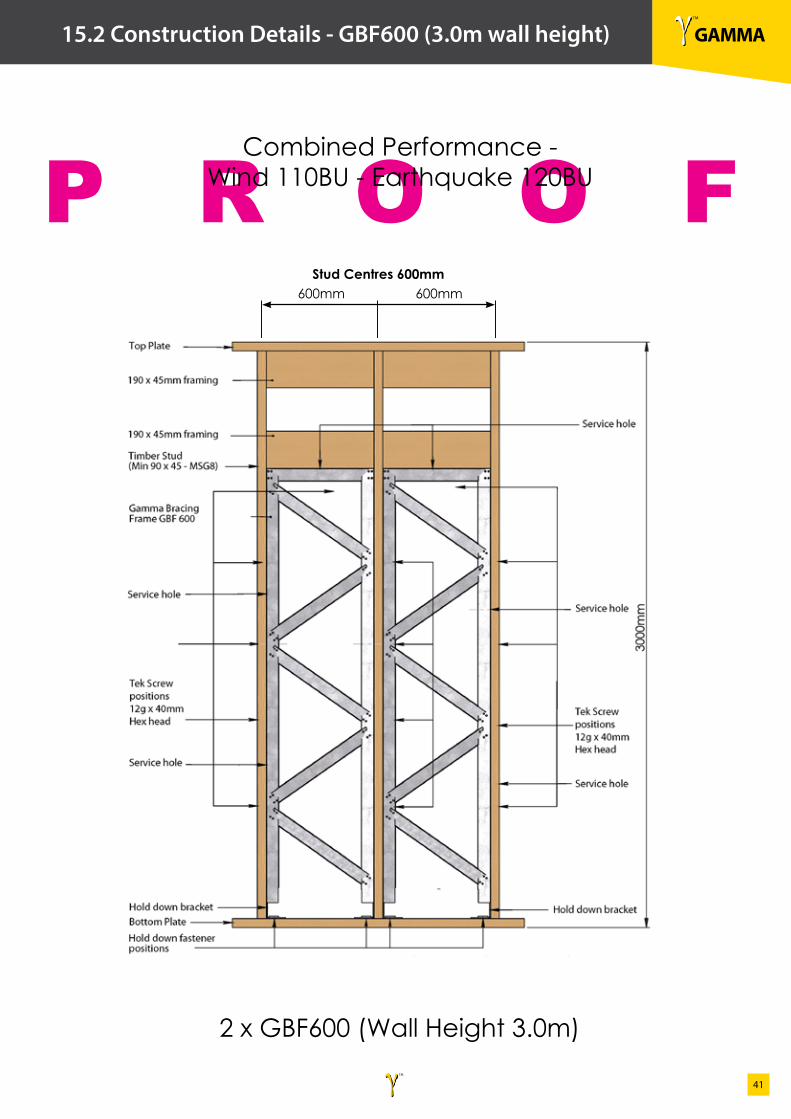
15.2 Construction Details - GBF600 (3.0m wall height)
Combined Performance - Wind 110BU - Earthquake 120BU
2 x GBF600 (Wall Height 3.0m)
Stud Centres 600mm600mm 600mm
γ TM
GAMMAγ TM
42
P R O O F
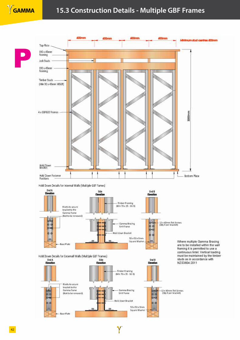
15.3 Construction Details - Multiple GBF Frames
γ TM
GAMMAγ TM
43
P R O O F
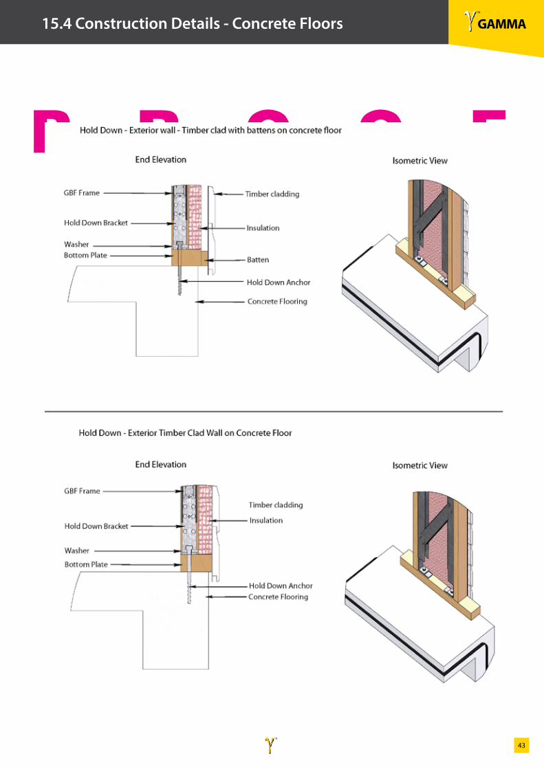
15.4 Construction Details - Concrete Floors
γ TM
GAMMAγ TM
44
P R O O F
15.5 Construction Details - Concrete Floors
γ TM
GAMMAγ TM
45
P R O O F
15.6 Construction Details - Timber Floors
γ TM
GAMMAγ TM
46
P R O O F
15.7 Construction Details - Timber Floors
γ TM
GAMMAγ TM
47
P R O O F
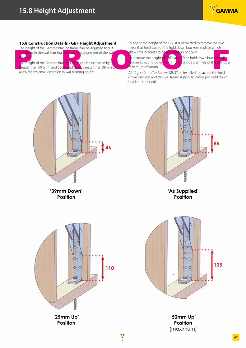
15.8 Height Adjustment
‘39mm Down’Position
46
110
85
135
‘25mm Up’Position
‘As Supplied’Position
‘50mm Up’Position
(maximum)
15.8 Construction Details - GBF Height AdjustmentThe height of the Gamma Bracing frame can be adjusted to suit variations in the wall framing height or the alignment of the wall framing.
The height of the Gamma Bracing Frame can be increased by no greater than 50.0mm and decreased by no greater than 39mm to allow for any small deviation in wall framing height.
To adjust the height of the GBF it is permitted to remove the two rivets that hold each of the hold down brackets in place which allows the brackets to be adjusted up or down.
To increase the height of GBF each of the hold down brackets will require adjusting downwards from the side channels of the GBF by a maximum of 50mm
All 12g x 40mm Tek Screws MUST be installed to each of the hold down brackets and the GBF frame. (Qty of 8 Screws per Hold down bracket - supplied).
γ TM
GAMMAγ TM
48
P R O O F
16.0 Ancillary Products
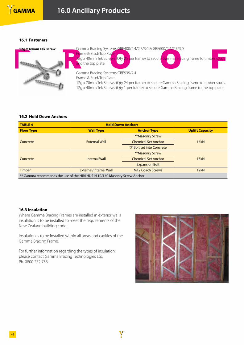
Gamma Bracing Systems GBF400/2.4/2.7/3.0 & GBF600/2.4/2.7/3.0. Frame & Stud/Top Plate: 12g x 40mm Tek Screws (Qty 25 per frame) to secure Gamma Bracing frame to timber studs and the top plate.
Gamma Bracing Systems GBF535/2.4 Frame & Stud/Top Plate: 12g x 70mm Tek Screws (Qty 24 per frame) to secure Gamma Bracing frame to timber studs. 12g x 40mm Tek Screws (Qty 1 per frame) to secure Gamma Bracing frame to the top plate.
16.1 Fasteners
12g x 40mm Tek screw
16.2 Hold Down Anchors
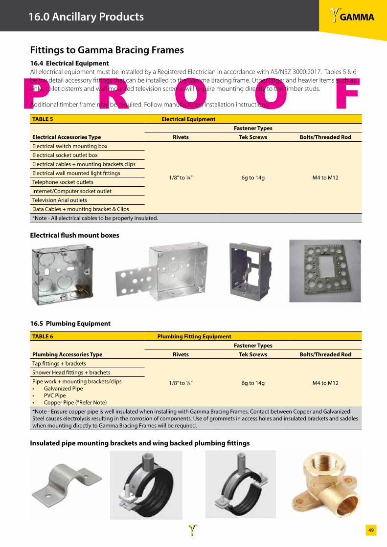
16.3 InsulationWhere Gamma Bracing Frames are installed in exterior walls insulation is to be installed to meet the requirements of the New Zealand building code.
Insulation is to be installed within all areas and cavities of the Gamma Bracing Frame.
For further information regarding the types of insulation, please contact Gamma Bracing Technologies Ltd, Ph. 0800 272 733.
TABLE 4 Hold Down AnchorsFloor Type Wall Type Anchor Type Uplift Capacity
Concrete External Wall
**Masonry Screw
15kNChemical Set Anchor
“J” Bolt set into Concrete
Concrete Internal Wall
**Masonry Screw
15kNChemical Set Anchor
Expansion Bolt
Timber External/Internal Wall M12 Coach Screws 12kN
** Gamma recommends the use of the Hilti HUS-H 10/140 Masonry Screw Anchor
γ TM
GAMMAγ TM
49
P R O O F
16.0 Ancillary Products
Fittings to Gamma Bracing Frames16.4 Electrical Equipment All electrical equipment must be installed by a Registered Electrician in accordance with AS/NSZ 3000:2017. Tables 5 & 6 below detail accessory fittings that can be installed to the Gamma Bracing frame. Other larger and heavier items such as sinks, toilet cistern’s and wall mounted television screens will require mounting directly to the timber studs.
Additional timber frame may be required. Follow manufacturers installation instructions.
Electrical flush mount boxes
Insulated pipe mounting brackets and wing backed plumbing fittings
TABLE 5 Electrical Equipment
Electrical Accessories TypeFastener Types
Rivets Tek Screws Bolts/Threaded RodElectrical switch mounting box
1/8” to ¼“ 6g to 14g M4 to M12
Electrical socket outlet box
Electrical cables + mounting brackets clips
Electrical wall mounted light fittings
Telephone socket outlets
Internet/Computer socket outlet
Television Arial outlets
Data Cables + mounting bracket & Clips
*Note - All electrical cables to be properly insulated.
TABLE 6 Plumbing Fitting Equipment
Plumbing Accessories TypeFastener Types
Rivets Tek Screws Bolts/Threaded RodTap fittings + brackets
1/8” to ¼“ 6g to 14g M4 to M12
Shower Head fittings + brachets
Pipe work + mounting brackets/clips• Galvanized Pipe• PVC Pipe• Copper Pipe (*Refer Note)
*Note - Ensure copper pipe is well insulated when installing with Gamma Bracing Frames. Contact between Copper and Galvanized Steel causes electrolysis resulting in the corrosion of components. Use of grommets in access holes and insulated brackets and saddles when mounting directly to Gamma Bracing Frames will be required.
16.5 Plumbing Equipment
γ TM
GAMMAγ TM
50
P R O O F
Notes
γ TM
GAMMAγ TM
51
P R O O F
Notes

γ TM
GAMMABRACING FRAME
GAMMAγ TM
Contact:FreePhone 0800 272 733website www.gammabracing.co.nz
692A Beach Road Browns BayNew Zealand 0630
Gamma Bracing Technologies™
Copyright 2014
TECHNICAL & SALES 0800 272 733
www.gammabracing.co.nz
For detailed specifications the most current Gamma Bracing System’s technical manual should always be referred to.
© 2014 Copyright: all the material in this document including all text, tables, diagrams and illustrations are protected by copyright.
Substitution: in order for Gamma Bracing Systems to perform as tested all components must be installed exactly as prescribed.
Substituting components produces an entirely different system and may seriously compromise performance.
Where specified, correct components must be used when installing and specifying Gamma Bracing Systems.