T.E.I. ΣΤΕΡΕΑΣ ΕΛΛΑΔΑΣ · Φασματοσκοπίας Novocontrol Alpha Broadband...
35
T.E.I. ΣΤΕΡΕΑΣ ΕΛΛΑΔΑΣ ΤΜΗΜΑ ΗΛΕΚΤΡΟΝΙΚΩΝ ΜΗΧΑΝΙΚΩΝ ΤΕ ΕΡΓΑΣΤΗΡΙΟ «ΗΛΕΚΤΡΟΝΙΚΕΣ ΔΙΑΤΑΞΕΙΣ ΦΑΣΜΑΤΟΣΚΟΠΙΑΣ» ΕΡΓΑΣΤΗΡΙΑΚΗ ΑΣΚΗΣΗ 3: “EΓΚΑΤΑΣΤΑΣΗ – ΛΕΙΤΟΥΡΓΙΑ- ΧΡΗΣΗ ΔΙΑΤΑΞΗΣ ΔΗΛΕΚΤΡΙΚΗΣ ΦΑΣΜΑΤΟΣΚΟΠΙΑΣ ΥΨΗΛΩΝ ΤΑΣΕΩΝ ΠΟΛΩΣΗΣ” Α.ΚΑΝΑΠΙΤΣΑΣ Καθηγητής ΛΑΜΙΑ 2013
Transcript of T.E.I. ΣΤΕΡΕΑΣ ΕΛΛΑΔΑΣ · Φασματοσκοπίας Novocontrol Alpha Broadband...

T.E.I. ΣΤΕΡΕΑΣ ΕΛΛΑΔΑΣ ΤΜΗΜΑ ΗΛΕΚΤΡΟΝΙΚΩΝ ΜΗΧΑΝΙΚΩΝ ΤΕ
ΕΡΓΑΣΤΗΡΙΟ
«ΗΛΕΚΤΡΟΝΙΚΕΣ ΔΙΑΤΑΞΕΙΣ ΦΑΣΜΑΤΟΣΚΟΠΙΑΣ»
ΕΡΓΑΣΤΗΡΙΑΚΗ ΑΣΚΗΣΗ 3: “EΓΚΑΤΑΣΤΑΣΗ – ΛΕΙΤΟΥΡΓΙΑ- ΧΡΗΣΗ ΔΙΑΤΑΞΗΣ ΔΗΛΕΚΤΡΙΚΗΣ ΦΑΣΜΑΤΟΣΚΟΠΙΑΣ ΥΨΗΛΩΝ ΤΑΣΕΩΝ ΠΟΛΩΣΗΣ”
Α.ΚΑΝΑΠΙΤΣΑΣ Καθηγητής
ΛΑΜΙΑ 2013

Στην παρούσα εργαστηριακή άσκηση θα μελετηθεί ο τρόπος εγκατάστασης, η υλοποίηση
της κατάλληλης συνδεσμολογίας και η λειτουργία της διάταξης Διηλεκτρικής
Φασματοσκοπίας Novocontrol Alpha Broadband High Voltage Booster.
Παρατίθενται παρακάτω οδηγίες και τεχνικά χαρακτηριστικά απο το εγχειρίδιο χρήσης
της διάταξης.
Broadband High VoltageBooster HVB 300
for Alpha-A
High ResolutionDielectric / Impedance
AnalyzerUser's Manual
Issue: 2/2008 Rev. 1.01 by Novocontrol Technologies
Novocontrol TechnologiesGmbH & Co. KGObererbacher Strasse 9D-56414 HundsangenGermany
Phone: ++(0) 64 35 - 96 23-0FAX: ++(0) 64 35 - 96 23-33Email: [email protected] http://www.novocontrol.de
Broadband High Voltage Booster HVB 300 for Alpha-A Analyzer User's Manual
_______________________________________________________________________________________________
2
Copyright @
Novocontrol Technologies GmbH & Co. KG 2004
Germany
Broadband High Voltage Booster HVB 300 for Alpha-A Analyzer User's Manual
_______________________________________________________________________________________________
3
Contents
1. Safety Precautions .............................................................................................42. Inspection............................................................................................................63. Introduction.........................................................................................................64. Instrument Description ......................................................................................7
4.1. Front Panel .......................................................................................................74.2. Rear Panel .......................................................................................................9
5. Novocontrol High Voltage Sample Cell BDS 1200HV ...................................136. Setting up the System for Measurement........................................................17
6.1. System Requirements ...................................................................................176.2. System Connections for High Voltage Measurements...............................18
7. Principle of Operation ......................................................................................208. Using DC-Bias...................................................................................................239. Breakdown, High Frequency and Load Considerations...............................2410. Calibrations.......................................................................................................2511. Operating the Alpha-A with HVB 300 by GPIB commands...........................2912. Technical Data ..................................................................................................3113. Test Sample Results ........................................................................................33
Broadband High Voltage Booster HVB 300 for Alpha-A Analyzer User's Manual
_______________________________________________________________________________________________
4
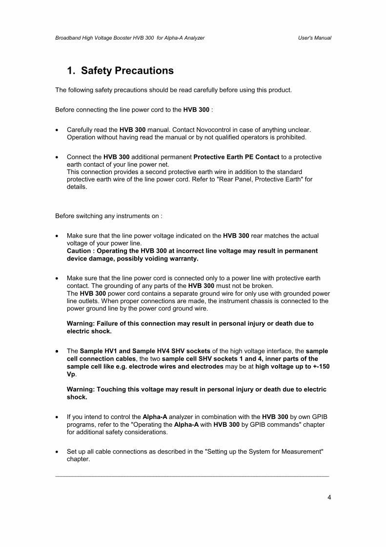
1. Safety Precautions
The following safety precautions should be read carefully before using this product.
Before connecting the line power cord to the HVB 300 :
• Carefully read the HVB 300 manual. Contact Novocontrol in case of anything unclear.Operation without having read the manual or by not qualified operators is prohibited.
• Connect the HVB 300 additional permanent Protective Earth PE Contact to a protectiveearth contact of your line power net.This connection provides a second protective earth wire in addition to the standardprotective earth wire of the line power cord. Refer to "Rear Panel, Protective Earth" fordetails.
Before switching any instruments on :
• Make sure that the line power voltage indicated on the HVB 300 rear matches the actualvoltage of your power line.Caution : Operating the HVB 300 at incorrect line voltage may result in permanentdevice damage, possibly voiding warranty.
• Make sure that the line power cord is connected only to a power line with protective earthcontact. The grounding of any parts of the HVB 300 must not be broken.The HVB 300 power cord contains a separate ground wire for only use with grounded powerline outlets. When proper connections are made, the instrument chassis is connected to thepower ground line by the power cord ground wire.
Warning: Failure of this connection may result in personal injury or death due toelectric shock.
•••• The Sample HV1 and Sample HV4 SHV sockets of the high voltage interface, the samplecell connection cables, the two sample cell SHV sockets 1 and 4, inner parts of thesample cell like e.g. electrode wires and electrodes may be at high voltage up to +-150Vp.
Warning: Touching this voltage may result in personal injury or death due to electricshock.
• If you intend to control the Alpha-A analyzer in combination with the HVB 300 by own GPIBprograms, refer to the "Operating the Alpha-A with HVB 300 by GPIB commands" chapterfor additional safety considerations.
• Set up all cable connections as described in the "Setting up the System for Measurement"chapter.
Broadband High Voltage Booster HVB 300 for Alpha-A Analyzer User's Manual
_______________________________________________________________________________________________
5
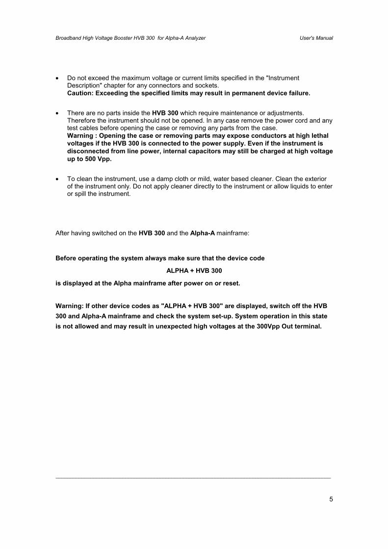
• Do not exceed the maximum voltage or current limits specified in the "InstrumentDescription" chapter for any connectors and sockets.Caution: Exceeding the specified limits may result in permanent device failure.
• There are no parts inside the HVB 300 which require maintenance or adjustments.Therefore the instrument should not be opened. In any case remove the power cord and anytest cables before opening the case or removing any parts from the case.Warning : Opening the case or removing parts may expose conductors at high lethalvoltages if the HVB 300 is connected to the power supply. Even if the instrument isdisconnected from line power, internal capacitors may still be charged at high voltageup to 500 Vpp.
• To clean the instrument, use a damp cloth or mild, water based cleaner. Clean the exteriorof the instrument only. Do not apply cleaner directly to the instrument or allow liquids to enteror spill the instrument.
After having switched on the HVB 300 and the Alpha-A mainframe:
Before operating the system always make sure that the device code
ALPHA + HVB 300
is displayed at the Alpha mainframe after power on or reset.
Warning: If other device codes as "ALPHA + HVB 300" are displayed, switch off the HVB300 and Alpha-A mainframe and check the system set-up. System operation in this stateis not allowed and may result in unexpected high voltages at the 300Vpp Out terminal.
Broadband High Voltage Booster HVB 300 for Alpha-A Analyzer User's Manual
_______________________________________________________________________________________________
6
2. Inspection
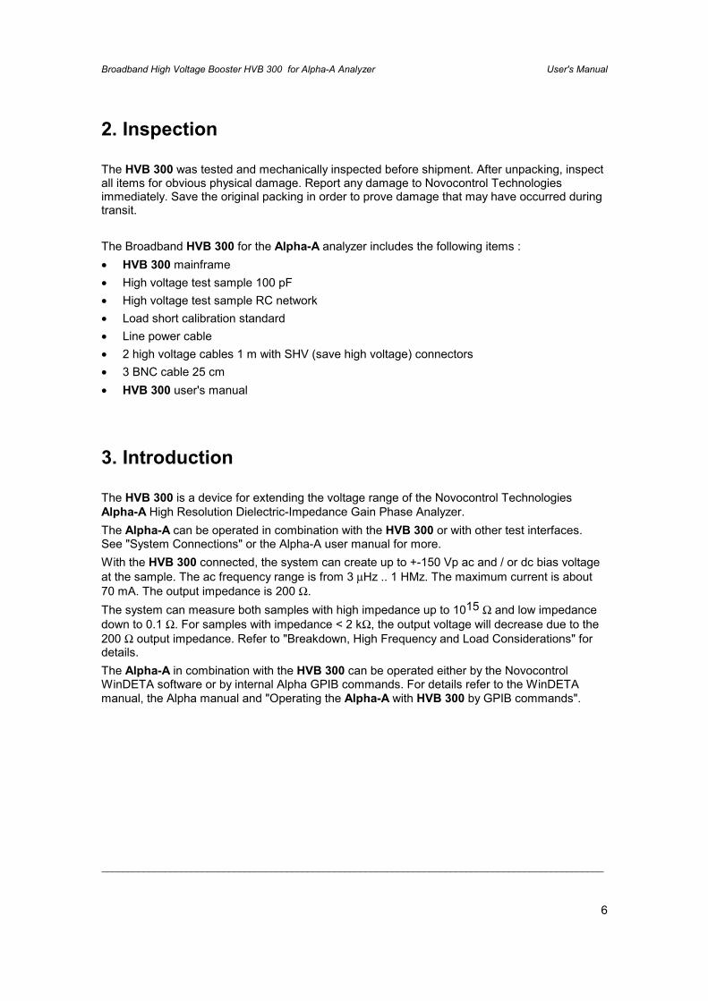
The HVB 300 was tested and mechanically inspected before shipment. After unpacking, inspectall items for obvious physical damage. Report any damage to Novocontrol Technologiesimmediately. Save the original packing in order to prove damage that may have occurred duringtransit.
The Broadband HVB 300 for the Alpha-A analyzer includes the following items :• HVB 300 mainframe• High voltage test sample 100 pF• High voltage test sample RC network• Load short calibration standard• Line power cable• 2 high voltage cables 1 m with SHV (save high voltage) connectors• 3 BNC cable 25 cm• HVB 300 user's manual
3. Introduction
The HVB 300 is a device for extending the voltage range of the Novocontrol TechnologiesAlpha-A High Resolution Dielectric-Impedance Gain Phase Analyzer.The Alpha-A can be operated in combination with the HVB 300 or with other test interfaces.See "System Connections" or the Alpha-A user manual for more.With the HVB 300 connected, the system can create up to +-150 Vp ac and / or dc bias voltageat the sample. The ac frequency range is from 3 µHz .. 1 HMz. The maximum current is about70 mA. The output impedance is 200 Ω.The system can measure both samples with high impedance up to 1015 Ω and low impedancedown to 0.1 Ω. For samples with impedance < 2 kΩ, the output voltage will decrease due to the200 Ω output impedance. Refer to "Breakdown, High Frequency and Load Considerations" fordetails.The Alpha-A in combination with the HVB 300 can be operated either by the NovocontrolWinDETA software or by internal Alpha GPIB commands. For details refer to the WinDETAmanual, the Alpha manual and "Operating the Alpha-A with HVB 300 by GPIB commands".
Broadband High Voltage Booster HVB 300 for Alpha-A Analyzer User's Manual
_______________________________________________________________________________________________
7
4. Instrument Description
4.1. Front Panel
HIGH VOLTAGE BOOSTER
Sample HV1300 Vpp Out
Sample HV4Current In
novocontrol
MainsVout [Vp]
0 150-150
Main PowerSwitch Vout Voltage
IndicatorBNC
SocketsSHV
Sockets
GEN
V1
V2
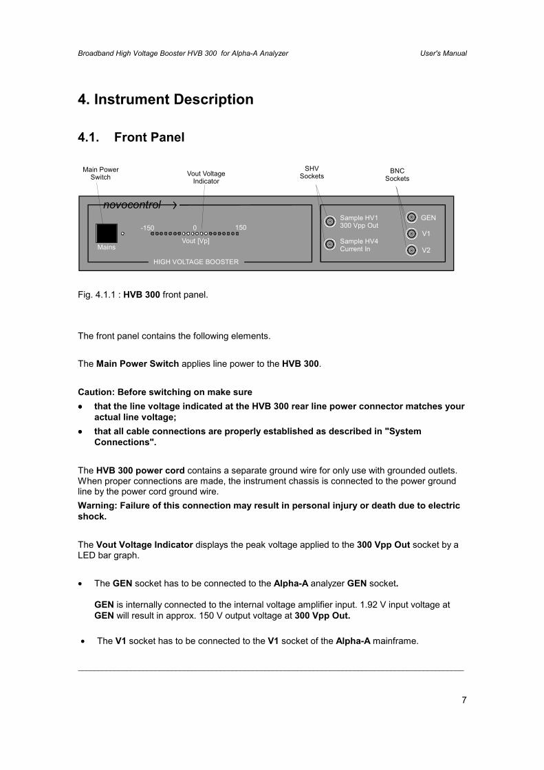
Fig. 4.1.1 : HVB 300 front panel.
The front panel contains the following elements.
The Main Power Switch applies line power to the HVB 300.
Caution: Before switching on make sure•••• that the line voltage indicated at the HVB 300 rear line power connector matches your
actual line voltage;•••• that all cable connections are properly established as described in "System
Connections".
The HVB 300 power cord contains a separate ground wire for only use with grounded outlets.When proper connections are made, the instrument chassis is connected to the power groundline by the power cord ground wire.Warning: Failure of this connection may result in personal injury or death due to electricshock.
The Vout Voltage Indicator displays the peak voltage applied to the 300 Vpp Out socket by aLED bar graph.
• The GEN socket has to be connected to the Alpha-A analyzer GEN socket.
GEN is internally connected to the internal voltage amplifier input. 1.92 V input voltage atGEN will result in approx. 150 V output voltage at 300 Vpp Out.
• The V1 socket has to be connected to the V1 socket of the Alpha-A mainframe.
Broadband High Voltage Booster HVB 300 for Alpha-A Analyzer User's Manual
_______________________________________________________________________________________________
8
V1 supplies a fraction of the 300 Vpp Out voltage created by an internal voltage divider.The maximum voltage at this pin is 4.5 Vp ac or / and dc.
This output is short protected to system ground. Do not apply any external voltages orcurrents.
• The V2 socket has to be connected to the V2 socket of the Alpha-A mainframe.
V2 provides the voltage output of the HVB 300 internal current to voltage converter.
This output is short protected to system ground. Do not apply any external voltages orcurrents.
• The 300 Vpp Out SHV socket has to be connected to signal source input of theNovocontrol BDS 1200HV high voltage sample cell or to any other sample impedanceunder test as the voltage source.
300 Vpp Out is internally connected via a 200 Ω resistor and a voltage activation switch tothe internal high voltage amplifier output. The maximum output voltage is about +-150 V acand / or dc. The current is limited to about 70 mA. The output impedance is 200 Ω. Thisoutput is short protected to system ground. Do not apply any external voltages or currents.
Caution: Connecting the 300 Vpp Out to any of the GEN, V1 or V2 sockets may result inpermanent damage of the instrument.
• The Current In SHV socket has to be connected to the current output of the NovocontrolBDS 1200HV high voltage sample cell or to any other sample impedance under test as thecurrent sense.
Current In is internally connected via an activation switch to the HVB 300 internal currentamplifier.
The maximum current is about +-70 mA ac and / or dc.
If Current In is internally connected, it will be at low impedance and with this at nearly zeropotential.
If Current In is internally disconnected, it will be at high impedance (open). In this case,Current In may be at the same potential as the 300 Vpp Out socket if connected via asample or sample cell.
The Current In socket input is protected against short circuits to the 300 Vpp Out socket.
Warning: Touching the voltage at the 300 Vpp Out or Current In sockets may result inpersonal injury or death due to electric shock.
Note: The cable connection between the 300 Vpp Out and Current In socket must have lowcapacity. Use only the original 1 m SHV cable supplied by Novocontrol.
Broadband High Voltage Booster HVB 300 for Alpha-A Analyzer User's Manual
_______________________________________________________________________________________________
9
4.2. Rear Panel
1A 230V50-60Hz
CE
LinePowerFuse
LinePower
Connector
Alpha-AActive
SampleCell
EnableVout
ProtectiveEarth
Alpha-A ActiveSample CellConnector
High VoltageOutput Enable
Switch
AdditionalPermanentPE Contact
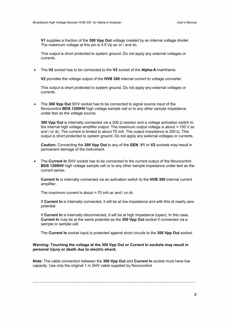
Fig. 4.2.1 : HVB 300 rear panel.
The rear panel contains the following elements :
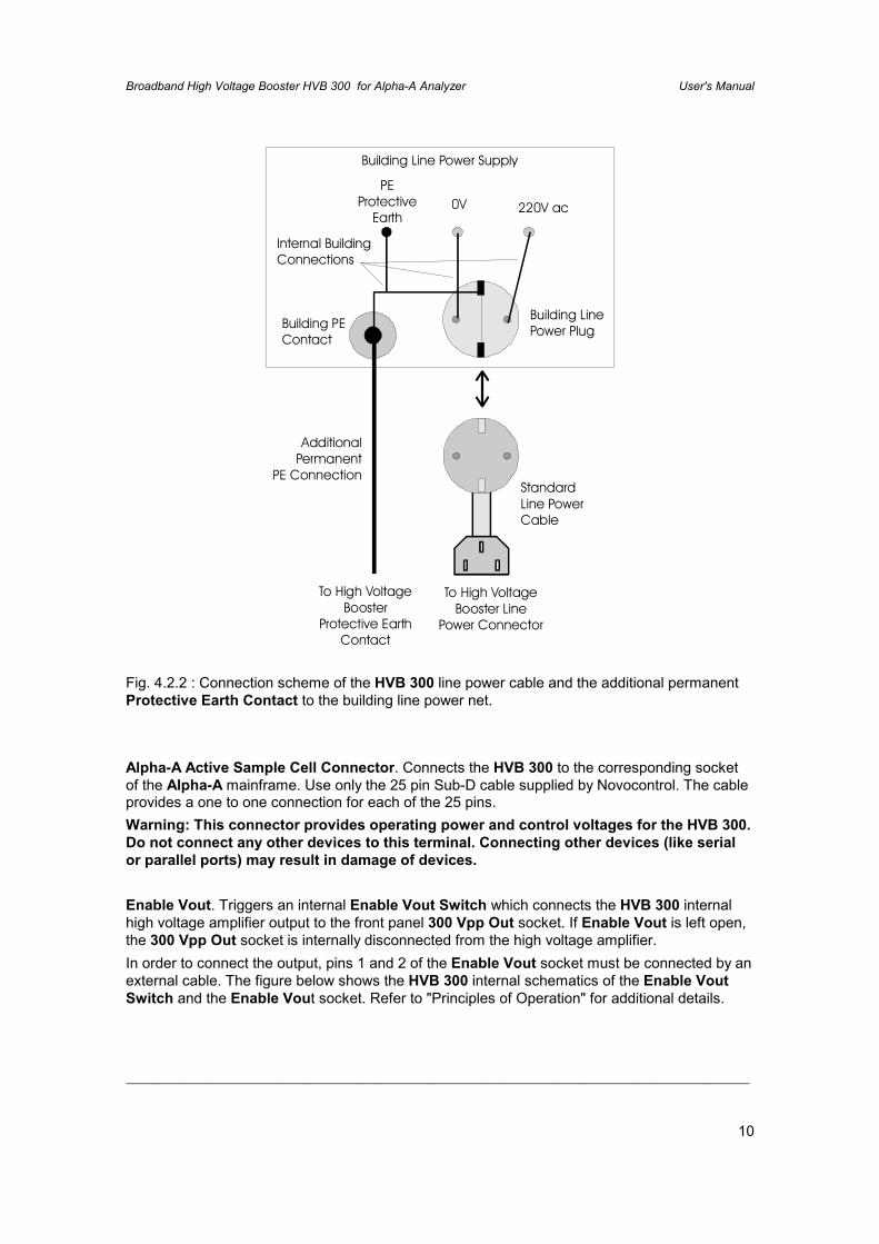
Additional permanent Protective Earth contact.This is a second protective earth connector (PE). The standard (first) PE connection is done bythe PE wire of the line power cord. As the HVB 300 internally builds up voltages up to 500 Vpp,for safety reasons a second PE connection should be established which grounds the instrumentin case of failure of the standard power cord PE wire. For this purpose the additional ProtectiveEarth Contact should be connected by a separate ground wire permanently to the protectiveearth potential of the building line power net. An example is shown below.
Broadband High Voltage Booster HVB 300 for Alpha-A Analyzer User's Manual
_______________________________________________________________________________________________
10
Building Line Power Supply
PEProtective
Earth0V 220V ac
Building LinePower PlugBuilding PE
Contact
StandardLine PowerCable
AdditionalPermanent
PE Connection
To High VoltageBooster Line
Power Connector
To High VoltageBooster
Protective EarthContact
Internal BuildingConnections
Fig. 4.2.2 : Connection scheme of the HVB 300 line power cable and the additional permanentProtective Earth Contact to the building line power net.
Alpha-A Active Sample Cell Connector. Connects the HVB 300 to the corresponding socketof the Alpha-A mainframe. Use only the 25 pin Sub-D cable supplied by Novocontrol. The cableprovides a one to one connection for each of the 25 pins.Warning: This connector provides operating power and control voltages for the HVB 300.Do not connect any other devices to this terminal. Connecting other devices (like serialor parallel ports) may result in damage of devices.
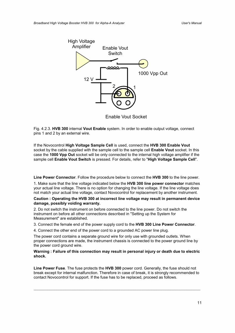
Enable Vout. Triggers an internal Enable Vout Switch which connects the HVB 300 internalhigh voltage amplifier output to the front panel 300 Vpp Out socket. If Enable Vout is left open,the 300 Vpp Out socket is internally disconnected from the high voltage amplifier.In order to connect the output, pins 1 and 2 of the Enable Vout socket must be connected by anexternal cable. The figure below shows the HVB 300 internal schematics of the Enable VoutSwitch and the Enable Vout socket. Refer to "Principles of Operation" for additional details.
Broadband High Voltage Booster HVB 300 for Alpha-A Analyzer User's Manual
_______________________________________________________________________________________________
11
Enable Vout Switch
High VoltageAmplifier
12 V2 1
Enable Vout Socket
1000 Vpp Out
Fig. 4.2.3. HVB 300 internal Vout Enable system. In order to enable output voltage, connectpins 1 and 2 by an external wire.
If the Novocontrol High Voltage Sample Cell is used, connect the HVB 300 Enable Voutsocket by the cable supplied with the sample cell to the sample cell Enable Vout socket. In thiscase the 1000 Vpp Out socket will be only connected to the internal high voltage amplifier if thesample cell Enable Vout Switch is pressed. For details, refer to "High Voltage Sample Cell".
Line Power Connector. Follow the procedure below to connect the HVB 300 to the line power.1. Make sure that the line voltage indicated below the HVB 300 line power connector matchesyour actual line voltage. There is no option for changing the line voltage. If the line voltage doesnot match your actual line voltage, contact Novocontrol for replacement by another instrument.Caution : Operating the HVB 300 at incorrect line voltage may result in permanent devicedamage, possibly voiding warranty.2. Do not switch the instrument on before connected to the line power. Do not switch theinstrument on before all other connections described in "Setting up the System forMeasurement" are established.3. Connect the female end of the power supply cord to the HVB 300 Line Power Connector.4. Connect the other end of the power cord to a grounded AC power line plug.The power cord contains a separate ground wire for only use with grounded outlets. Whenproper connections are made, the instrument chassis is connected to the power ground line bythe power cord ground wire.Warning : Failure of this connection may result in personal injury or death due to electricshock.
Line Power Fuse. The fuse protects the HVB 300 power cord. Generally, the fuse should notbreak except for internal malfunction. Therefore in case of break, it is strongly recommended tocontact Novocontrol for support. If the fuse has to be replaced, proceed as follows.
Broadband High Voltage Booster HVB 300 for Alpha-A Analyzer User's Manual
_______________________________________________________________________________________________
12
1. Switch the instrument off. Disconnect the power cord first from the line power and than fromthe HVB 300 Line Power Connector.2. Replace the fuse by the following type :
1A, slow blow for line voltage 220V-240V

Broadband High Voltage Booster HVB 300 for Alpha-A Analyzer User's Manual
_______________________________________________________________________________________________
13
5. Novocontrol High Voltage Sample Cell BDS 1200HV
Upper Electrode(Current Sense)
SampleMountingScrew
IsolationHousing
ElectrodeConnectors
Upper ElectrodeSHV Connector
Lower ElectrodeSHV Connector
Enable VoutConnector
PT100Connector
Enable VoutSwitch
Lower CellFixing Screw
Lower Electrode(AC/DC SignalSource)
PT100TemperatureSensor
HV1HV4
Fig. 5.1: High Voltage Sample Cell
The High Voltage Sample Cell contains the following elements :
Lower Electrode SHV ConnectorThe inner contact of this Save High Voltage connector is connected to the lower sampleelectrode. The outer contact is connected to the cell case. This socket should be connected by aSHV BNC cable to the signal source. For the HVB 300 this is the 300 Vpp Out socket.
Upper Electrode SHV ConnectorThe inner contact of this Save High Voltage connector is connected to the upper sampleelectrode. The outer contact is connected to the cell case. This socket should be connected by aSHV BNC cable to the current sense of the impedance measurement instrument. For the HVB300 this is the Current In socket.
Broadband High Voltage Booster HVB 300 for Alpha-A Analyzer User's Manual
_______________________________________________________________________________________________
14
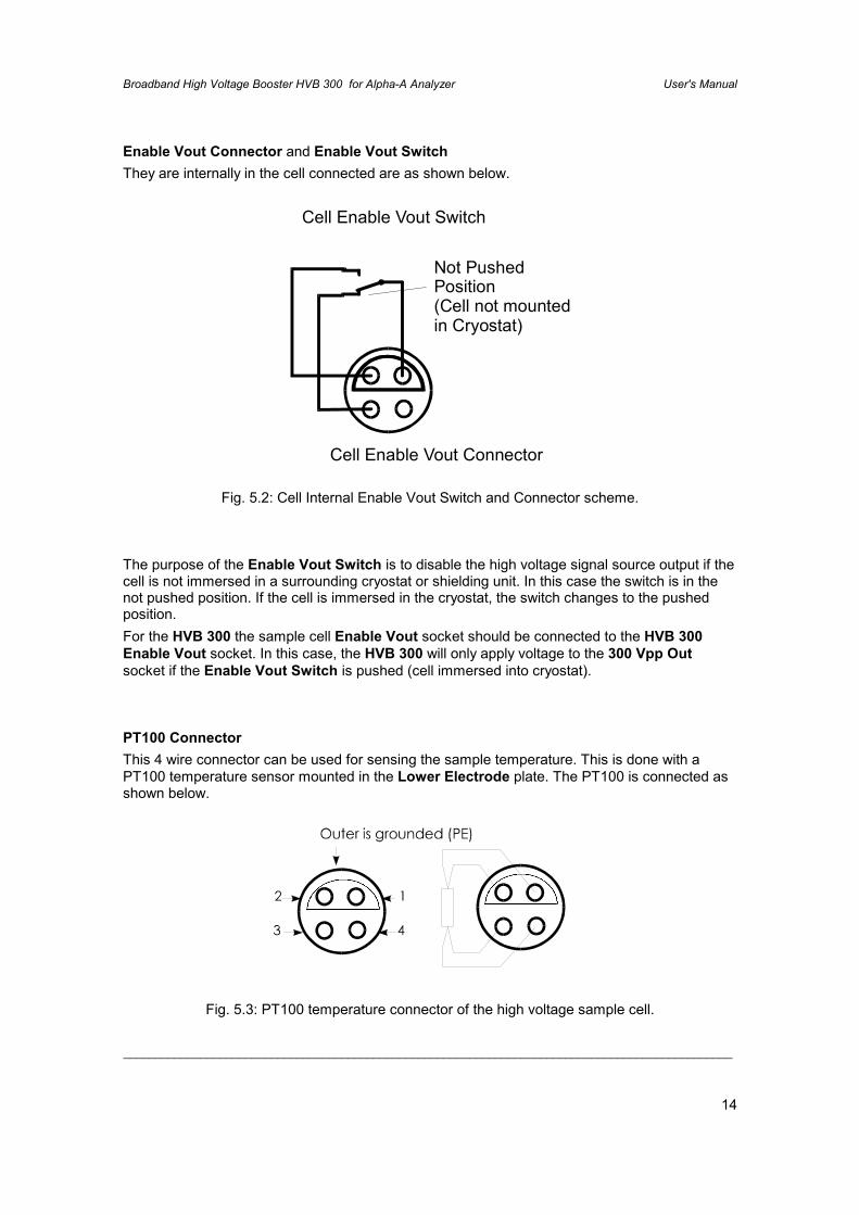
Enable Vout Connector and Enable Vout SwitchThey are internally in the cell connected are as shown below.
Cell Enable Vout Switch
Cell Enable Vout Connector
Not PushedPosition(Cell not mountedin Cryostat)
Fig. 5.2: Cell Internal Enable Vout Switch and Connector scheme.
The purpose of the Enable Vout Switch is to disable the high voltage signal source output if thecell is not immersed in a surrounding cryostat or shielding unit. In this case the switch is in thenot pushed position. If the cell is immersed in the cryostat, the switch changes to the pushedposition.For the HVB 300 the sample cell Enable Vout socket should be connected to the HVB 300Enable Vout socket. In this case, the HVB 300 will only apply voltage to the 300 Vpp Outsocket if the Enable Vout Switch is pushed (cell immersed into cryostat).
PT100 ConnectorThis 4 wire connector can be used for sensing the sample temperature. This is done with aPT100 temperature sensor mounted in the Lower Electrode plate. The PT100 is connected asshown below.
Fig. 5.3: PT100 temperature connector of the high voltage sample cell.
Broadband High Voltage Booster HVB 300 for Alpha-A Analyzer User's Manual
_______________________________________________________________________________________________
15
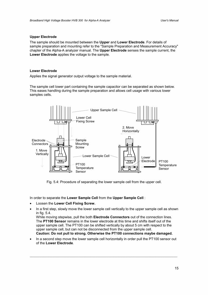
Upper ElectrodeThe sample should be mounted between the Upper and Lower Electrode. For details ofsample preparation and mounting refer to the "Sample Preparation and Measurement Accuracy"chapter of the Alpha-A analyzer manual. The Upper Electrode senses the sample current, theLower Electrode applies the voltage to the sample.
Lower ElectrodeApplies the signal generator output voltage to the sample material.
The sample cell lower part containing the sample capacitor can be separated as shown below.This eases handling during the sample preparation and allows cell usage with various lowersamples cells.
SampleMountingScrew
Lower Sample Cell
Upper Sample Cell
ElectrodeConnectors
1. MoveVertically
2. MoveHorizontally
Lower CellFixing Screw
PT100TemperatureSensor
PT100TemperatureSensor
LowerElectrode
Fig. 5.4: Procedure of separating the lower sample cell from the upper cell.
In order to separate the Lower Sample Cell from the Upper Sample Cell :• Loosen the Lower Cell Fixing Screw.• In a first step, slowly move the lower sample cell vertically to the upper sample cell as shown
in fig. 5.4.While moving stepwise, pull the both Electrode Connectors out of the connection lines.The PT100 Sensor remains in the lower electrode at this time and shifts itself out of theupper sample cell. The PT100 can be shifted vertically by about 5 cm with respect to theupper sample cell, but can not be disconnected from the upper sample cell.Caution: Do not pull to strong. Otherwise the PT100 connections maybe damaged.
• In a second step move the lower sample cell horizontally in order pull the PT100 sensor outof the Lower Electrode.
Broadband High Voltage Booster HVB 300 for Alpha-A Analyzer User's Manual
_______________________________________________________________________________________________
16
Important : If the lower sample cell has to be re-mounted after separation, connect theupper electrode to the thicker line of the upper sample cell and the lower electrode to thethinner line. The connections must not be exchanged.
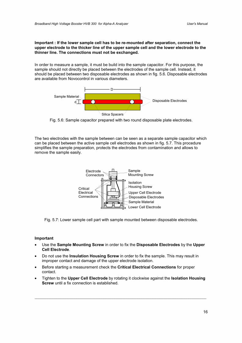
In order to measure a sample, it must be build into the sample capacitor. For this purpose, thesample should not directly be placed between the electrodes of the sample cell. Instead, itshould be placed between two disposable electrodes as shown in fig. 5.6. Disposable electrodesare available from Novocontrol in various diameters.
Disposable ElectrodesSample Material
Silica Spacers
D
d
Fig. 5.6: Sample capacitor prepared with two round disposable plate electrodes.
The two electrodes with the sample between can be seen as a separate sample capacitor whichcan be placed between the active sample cell electrodes as shown in fig. 5.7. This proceduresimplifies the sample preparation, protects the electrodes from contamination and allows toremove the sample easily.
SampleMounting Screw
ElectrodeConnectors
CriticalElectricalConnections
Lower Cell Electrode
Disposable ElectrodesSample Material
Upper Cell Electrode
IsolationHousing Screw
Fig. 5.7: Lower sample cell part with sample mounted between disposable electrodes.
Important• Use the Sample Mounting Screw in order to fix the Disposable Electrodes by the Upper
Cell Electrode.• Do not use the Insulation Housing Screw in order to fix the sample. This may result in
improper contact and damage of the upper electrode isolation.• Before starting a measurement check the Critical Electrical Connections for proper
contact.• Tighten to the Upper Cell Electrode by rotating it clockwise against the Isolation Housing
Screw until a fix connection is established.
Broadband High Voltage Booster HVB 300 for Alpha-A Analyzer User's Manual
_______________________________________________________________________________________________
17
• Tighten the screw of the Lower Cell Electrode connection wire with screw driver until a fixconnection is established.
• Check the two Electrode Connectors for proper contact with the upper sample cellconnection lines.
• From time to time, all four Critical Electrical Connections contacts should be cleaned andpolished in order to remove insulating oxide layers. This applies especially if the cell wasexposed to high temperatures before.
For this purpose :• Remove the Upper Cell Electrode by rotating it anti clockwise against the Isolation
Housing Screw,• Remove the Lower Cell Electrode connection wire by unscrewing it from the Lower Cell
Electrode,• Pull the two electrode connectors out of the upper sample cell connections lines.
For additional sample preparation hints, refer to "Sample Preparation" in the Alpha analyzermanual.
6. Setting up the System for Measurement
6.1. System Requirements
You must have the following components in order to operate the HVB 300 in combination withan Alpha-A analyzer.
• A Novocontrol HVB 300.
• An Novocontrol Technologies Alpha-A High Resolution Dielectric Analyzer.
• For dielectric material measurements a suitable sample cell is required. The NovocontrolHigh Voltage Sample Cell is recommended.
The system has to be operated under control of a separate host computer by the GPIB IEEE488 bus and an additional software package. You can either use standard software fromNovocontrol or own written software.
If you intend to control the Alpha-A in combination with the HVB 300 by own software, refer tothe "Operating the Alpha-A with HVB 300 by GPIB commands" chapter. The followingcomponents are required.
• A standard software development tool like e.g. a Basic interpreter or C compiler.
Broadband High Voltage Booster HVB 300 for Alpha-A Analyzer User's Manual
_______________________________________________________________________________________________
18
• A host computer with an GPIB IEEE 488 interface port. The computer and the IEEE 488interface must match to the software development tool.
The Novocontrol WinDETA / WinIMP software supports dielectric and impedancemeasurements with optional support of temperature control. You must have the followingcomponents in order to operate the Alpha-A in combination with the HVB 300 by WinDETA orWinIMP.
• The WinDETA or WinIMP software package from Novocontrol.
• Either a Novocontrol GPIB card or a National Instruments GPIB card which matches yourMS-Windows system for remote control of the Alpha analyzer.
• An IBM compatible PC with a 486 or higher processor with at least 16 MB memory and MS-Windows95, 98 or NT operating system. A PC with a Pentium processor is recommended.
• If temperature control for the sample cell (Alpha-A + HVB 300 in combination with aNovocontrol High Voltage Sample Cell) is required : The Novocontrol WinDETA software,a Novocontrol temperature control system based on the QUATRO, Novocool, orNovotherm controller or another temperature control system based on an Eurotherm 818or 2400 series temperature controllers.
6.2. System Connections for High Voltage MeasurementsIn order to set up the Alpha-A analyzer in combination with the HVB 300 for a dielectric materialor impedance measurement, the following connections have to done.
Caution : Before setting up any connections :•••• Switch off the HVB 300 and all devices connected to it.•••• Switch off the Alpha-A analyzer and all devices connected to it.•••• Set up all connections as described in the "Rear Panel" chapter.•••• Respect the voltage and current limitations described in the "Front Panel" chapter.
Broadband High Voltage Booster HVB 300 for Alpha-A Analyzer User's Manual
_______________________________________________________________________________________________
19
Upper Electrode(Current Sense)
Lower Electrode(AC Signal Source)
PT100TemperatureSensor
NovocontrolBDS 1200Sample Cell
PT100EnableVout
EnableVout Switch
To Enable Voutat High Voltage BoosterRear Side
HV1HV4
HIGH RESOLUTION DIELECTRIC ANALYZER
Sample HI
Sample LO
Curr. OUT
GEN
V1
V2
ALPHA + HVB 300 V4.3ANB IEC=10Novocontrol Technologies
HIGH VOLTAGE BOOSTER
Sample HV1300 Vpp Out
Sample HV4Current In
novocontrol
MainsVout [Vp]
0 150-150GEN
V1
V2
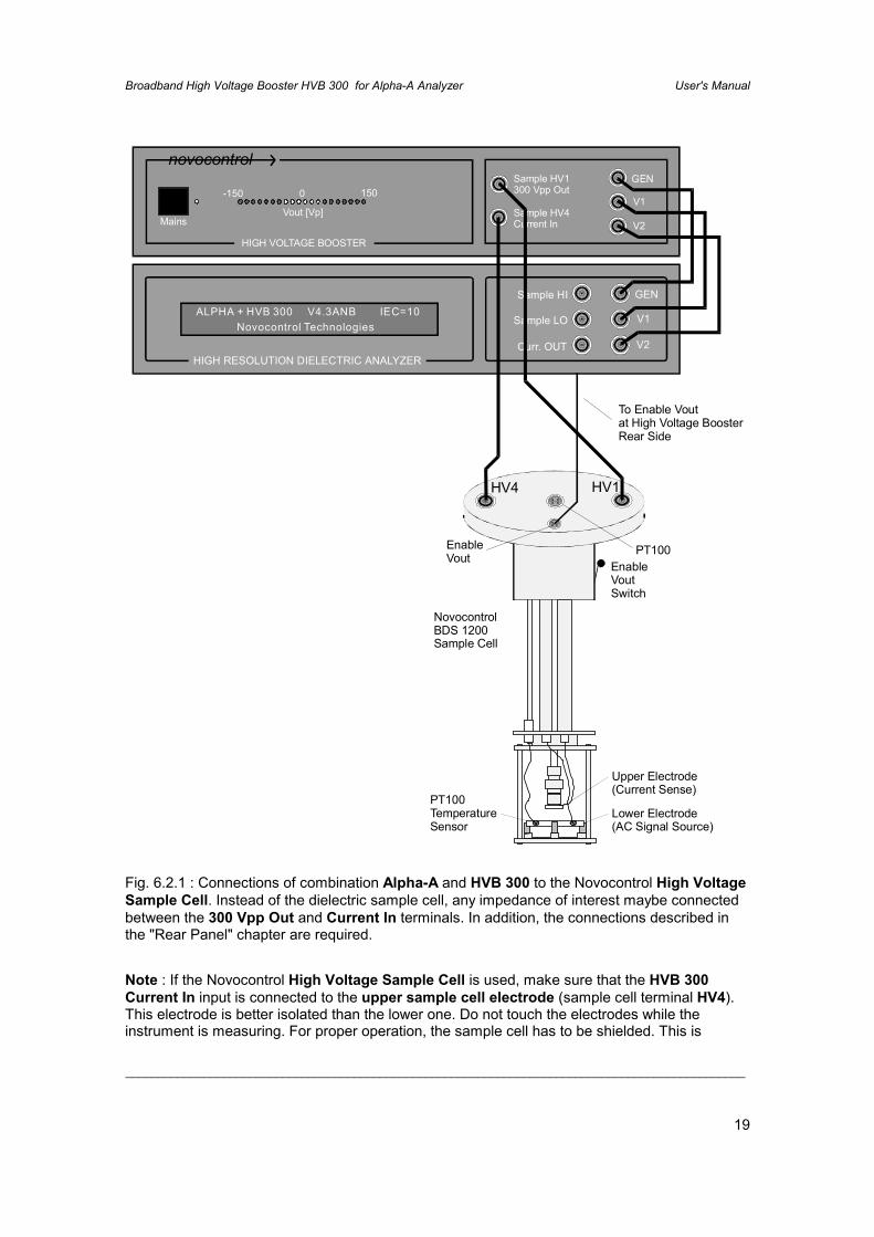
Fig. 6.2.1 : Connections of combination Alpha-A and HVB 300 to the Novocontrol High VoltageSample Cell. Instead of the dielectric sample cell, any impedance of interest maybe connectedbetween the 300 Vpp Out and Current In terminals. In addition, the connections described inthe "Rear Panel" chapter are required.
Note : If the Novocontrol High Voltage Sample Cell is used, make sure that the HVB 300Current In input is connected to the upper sample cell electrode (sample cell terminal HV4).This electrode is better isolated than the lower one. Do not touch the electrodes while theinstrument is measuring. For proper operation, the sample cell has to be shielded. This is
Broadband High Voltage Booster HVB 300 for Alpha-A Analyzer User's Manual
_______________________________________________________________________________________________
20
generally done by placing it into a grounded metal cryostat or a metal shielding tube. Both areavailable by Novocontrol.
Warning: The 300 Vpp Out and Current In sockets may be at high voltage up to +-150 Vp acand / or dc. In addition high voltage may be at the sample cell electrodes, electrodeconnection wires and the lines inside the sample cell. Touching any of those conductorsmay result in personal injury or death due to electric shock.
The system may now be switched on. It is recommended to first switch the HVB 300 on andthen the Alpha-A mainframe. The Alpha-A mainframe should after about 10 seconds show in itsdisplay the following boot message.
ALPHA + HVB 300 V4.3ANB IEC=10 Novocontrol Technologies
which indicates that the HVB 300 was properly detected by the mainframe.
Before operating the system always make sure that the device codeALPHA + HVB 300
is displayed after power on or reset.
Warning: If other device codes as "ALPHA + HVB 300" are displayed, switch off thesystem and check the set-up. System operation in this state is not allowed and may resultin unexpected high voltages at the 300 Vpp Out terminal.
7. Principle of Operation
The principal setup of the high voltage system is shown below.

Broadband High Voltage Booster HVB 300 for Alpha-A Analyzer User's Manual
_______________________________________________________________________________________________
21
GEN
200 ΩVoltage Indicator
High VoltageBooster
VoltageDivider
/78V1
300 Vpp Out
I->V ConverterReferenceCapacitor
SystemGround
(PE)
InternalConnection
Enable Vout
SampleImpedance
V2
Current In
*78
Alpha-AAnalyzer
GEN
V2
V1
Fig. 7.1 : Principle schematic of the Alpha-A analyzer in combination with the HVB 300.
The internal Alpha-A ac generator (at GEN) creates an ac voltage in the range 0 V .. 1.92 Vp.The signal maybe superimposed by an additional dc bias from -1.92 V .. 1.92 V. Both signals arelimited by software, so that the total voltage at the GEN socket does not exceed +-1.92 Vp.The GEN signal is externally connected via the HVB 300 GEN socket to the high voltageamplifier and increased by a factor ~78. The maximum output voltage which may contain bothac and dc contributions is +-150 Vp. The amplifier current is limited to +-70 mA. The outputimpedance is adjusted to 200 Ω by an output resistor. This signal is applied via the internalEnable Vout Safety Switch to the 300 Vpp Out socket.
The Enable Vout Safety Switch is normally open and in this state the output voltage isdisabled. In operating mode, the Enable Vout Safety Switch has to be closed by applying anexternal connection to the Enable Vout Connector at the HVB 300 rear. Refer to "Rear Panel"and "High Voltage Sample Cell" for details.
Broadband High Voltage Booster HVB 300 for Alpha-A Analyzer User's Manual
_______________________________________________________________________________________________
22
The output voltage peak amplitude at the 300 Vpp Out socket is displayed by the VoltageIndicator.
The 300 Vpp Out signal is further applied to the Voltage Divider, reduced by a factor ~78 andapplied via the two V1 sockets to the Alpha input voltage Channel 1.
The 300 Vpp Out signal is applied in addition either to the the internal variable ReferenceCapacitor or the Sample Impedance.
The sample current is sensed by the Current In socket.
The reference capacitor or the sample can be connected by two internal switches to the HVB300 current input. The current input has low impedance and therefore is nearly at groundpotential. The sample or reference current is converted by the I -> V Converter into a voltagewhich is measured by the analyzer voltage Channel 2.
Refer to the Alpha manual for further details on voltage measurement, sine wave correlationtechnique, current to voltage conversion, impedance measurement and reference technique.
Broadband High Voltage Booster HVB 300 for Alpha-A Analyzer User's Manual
_______________________________________________________________________________________________
23
8. Using DC-Bias
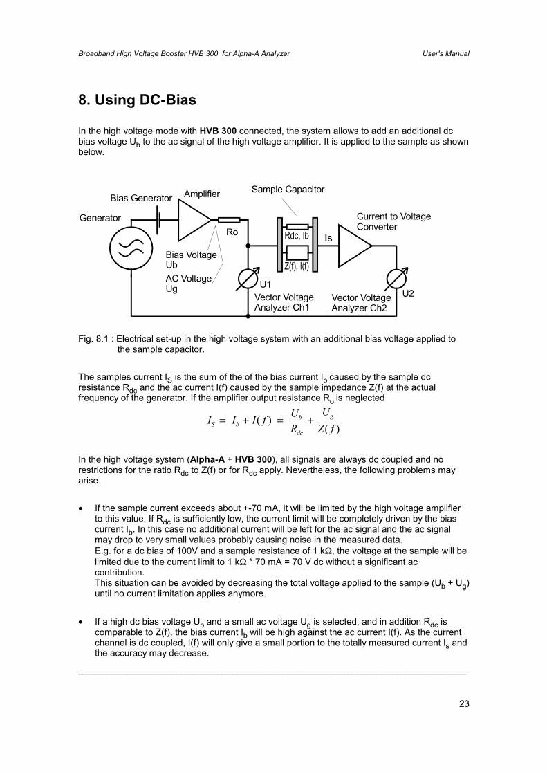
In the high voltage mode with HVB 300 connected, the system allows to add an additional dcbias voltage Ub to the ac signal of the high voltage amplifier. It is applied to the sample as shownbelow.
Fig. 8.1 : Electrical set-up in the high voltage system with an additional bias voltage applied tothe sample capacitor.
The samples current IS is the sum of the of the bias current Ib caused by the sample dcresistance Rdc and the ac current I(f) caused by the sample impedance Z(f) at the actualfrequency of the generator. If the amplifier output resistance Ro is neglected
I I I f UR
UZ fS b
b
dc
g= + = +( )( )
In the high voltage system (Alpha-A + HVB 300), all signals are always dc coupled and norestrictions for the ratio Rdc to Z(f) or for Rdc apply. Nevertheless, the following problems mayarise.
• If the sample current exceeds about +-70 mA, it will be limited by the high voltage amplifierto this value. If Rdc is sufficiently low, the current limit will be completely driven by the biascurrent Ib. In this case no additional current will be left for the ac signal and the ac signalmay drop to very small values probably causing noise in the measured data.E.g. for a dc bias of 100V and a sample resistance of 1 kΩ, the voltage at the sample will belimited due to the current limit to 1 kΩ * 70 mA = 70 V dc without a significant accontribution.This situation can be avoided by decreasing the total voltage applied to the sample (Ub + Ug)until no current limitation applies anymore.
• If a high dc bias voltage Ub and a small ac voltage Ug is selected, and in addition Rdc iscomparable to Z(f), the bias current Ib will be high against the ac current I(f). As the currentchannel is dc coupled, I(f) will only give a small portion to the totally measured current Is andthe accuracy may decrease.
Bias Generator Amplifier Sample Capacitor
Current to VoltageConverter
Vector VoltageAnalyzer Ch2
Vector VoltageAnalyzer Ch1
U1U2
Bias VoltageUbAC VoltageUg
GeneratorRo
Broadband High Voltage Booster HVB 300 for Alpha-A Analyzer User's Manual
_______________________________________________________________________________________________
24
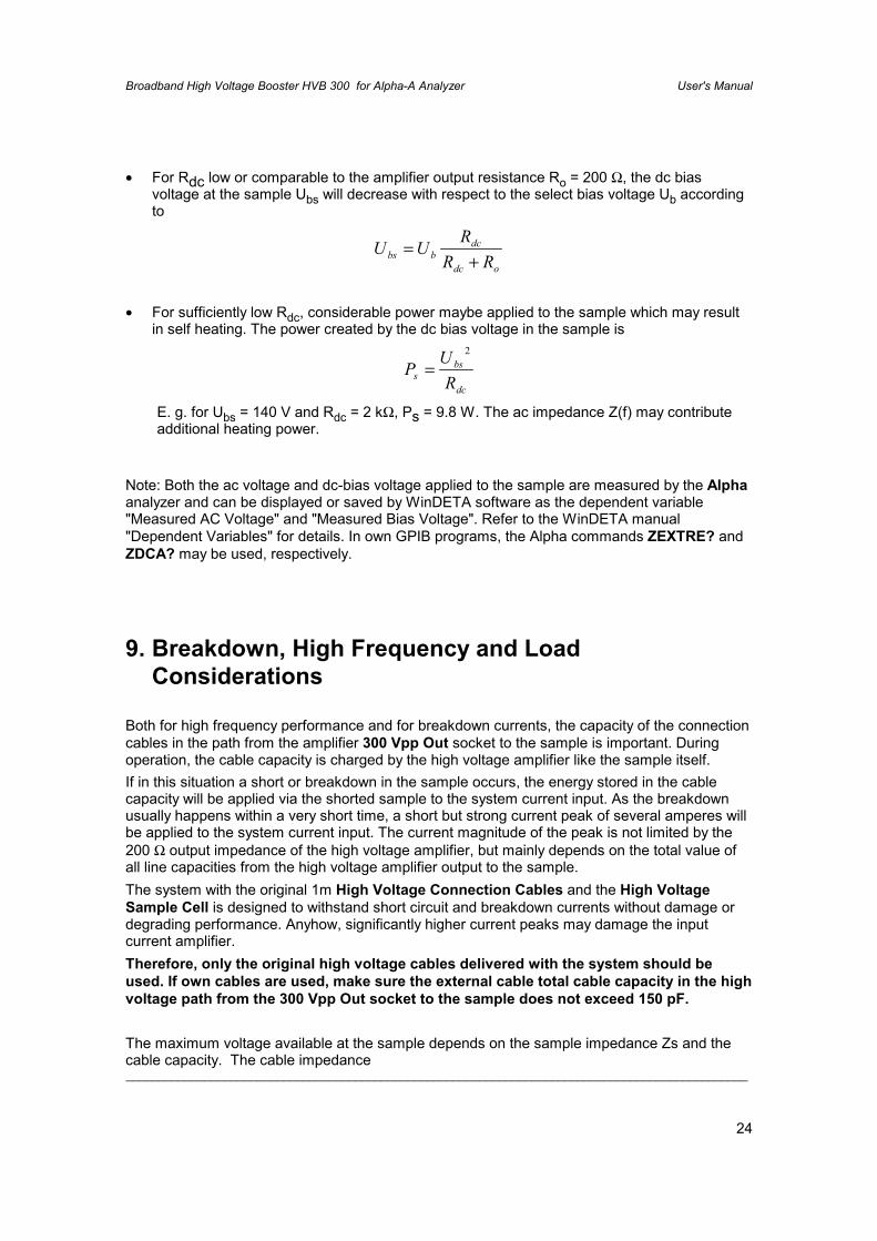
• For Rdc low or comparable to the amplifier output resistance Ro = 200 Ω, the dc biasvoltage at the sample Ubs will decrease with respect to the select bias voltage Ub accordingto
odc
dcbbs RR
RUU
+=
• For sufficiently low Rdc, considerable power maybe applied to the sample which may resultin self heating. The power created by the dc bias voltage in the sample is
dc
bss RUP
2
=
E. g. for Ubs = 140 V and Rdc = 2 kΩ, Ps = 9.8 W. The ac impedance Z(f) may contributeadditional heating power.
Note: Both the ac voltage and dc-bias voltage applied to the sample are measured by the Alphaanalyzer and can be displayed or saved by WinDETA software as the dependent variable"Measured AC Voltage" and "Measured Bias Voltage". Refer to the WinDETA manual"Dependent Variables" for details. In own GPIB programs, the Alpha commands ZEXTRE? andZDCA? may be used, respectively.
9. Breakdown, High Frequency and LoadConsiderations
Both for high frequency performance and for breakdown currents, the capacity of the connectioncables in the path from the amplifier 300 Vpp Out socket to the sample is important. Duringoperation, the cable capacity is charged by the high voltage amplifier like the sample itself.If in this situation a short or breakdown in the sample occurs, the energy stored in the cablecapacity will be applied via the shorted sample to the system current input. As the breakdownusually happens within a very short time, a short but strong current peak of several amperes willbe applied to the system current input. The current magnitude of the peak is not limited by the200 Ω output impedance of the high voltage amplifier, but mainly depends on the total value ofall line capacities from the high voltage amplifier output to the sample.The system with the original 1m High Voltage Connection Cables and the High VoltageSample Cell is designed to withstand short circuit and breakdown currents without damage ordegrading performance. Anyhow, significantly higher current peaks may damage the inputcurrent amplifier.Therefore, only the original high voltage cables delivered with the system should beused. If own cables are used, make sure the external cable total cable capacity in the highvoltage path from the 300 Vpp Out socket to the sample does not exceed 150 pF.
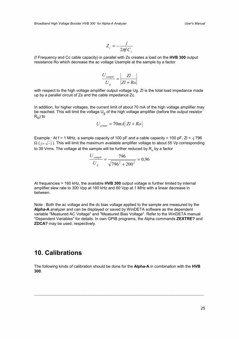
The maximum voltage available at the sample depends on the sample impedance Zs and thecable capacity. The cable impedance
Broadband High Voltage Booster HVB 300 for Alpha-A Analyzer User's Manual
_______________________________________________________________________________________________
25
cc Cf
jZπ2
−=
(f Frequency and Cc cable capacity) in parallel with Zs creates a load on the HVB 300 outputresistance Ro which decrease the ac voltage Usample at the sample by a factor
RoZlZl
UU
g
sample
+=
with respect to the high voltage amplifier output voltage Ug. Zl is the total load impedance madeup by a parallel circuit of Zs and the cable impedance Zc.
In addition, for higher voltages, the current limit of about 70 mA of the high voltage amplifier maybe reached. This will limit the voltage Ug of the high voltage amplifier (before the output resistorRo) to
RoZlmAU g += 70max
Example : At f = 1 MHz, a sample capacity of 100 pF and a cable capacity = 100 pF, Zl = -j 796Ω ( j = −1 ). This will limit the maximum available amplifier voltage to about 55 Vp correspondingto 39 Vrms. The voltage at the sample will be further reduced by Ro by a factor
96,0200796
79622
=+
=g
sample
UU
At frequencies > 160 kHz, the available HVB 300 output voltage is further limited by internalamplifier slew rate to 300 Vpp at 160 kHz and 60 Vpp at 1 MHz with a linear decrease inbetween.
Note : Both the ac voltage and the dc bias voltage applied to the sample are measured by theAlpha-A analyzer and can be displayed or saved by WinDETA software as the dependentvariable "Measured AC Voltage" and "Measured Bias Voltage". Refer to the WinDETA manual"Dependent Variables" for details. In own GPIB programs, the Alpha commands ZEXTRE? andZDCA? may be used, respectively.
10. Calibrations
The following kinds of calibration should be done for the Alpha-A in combination with the HVB300.
Broadband High Voltage Booster HVB 300 for Alpha-A Analyzer User's Manual
_______________________________________________________________________________________________
26
1. Internal Alpha All Calibration of the amplification and phase shifts of the HVB 300impedance converter measurement ranges.
-Disconnect the cables from the 300 Vpp Vout and Current In terminals before starting thecalibration.
-Make sure that the HVB 300 internal Enable Vout switch is closed. For details refer to "RearPanel, Enable Vout". If you are using the High Voltage Sample Cell, place the cell into acryostat or shielding unit in order close the Enable Vout switch.
In order to start the calibration with WinDETA:-Make sure that in the WinDETA "Analyzers" menu, "Alpha + High Volt Amp. +- 150Vp" isselected as the actual impedance system.-Select "Calibrate BDC or Alpha All" from the WinDETA menu item "Analyzers, Options(Alpha + High Voltage Amp. +-150Vp).
In order to start the calibration by own GPIB programs:-Use the GPIB commands *RST, ZRUNCAL=ALL_INIT and ZRUNCAL=ALL.
This calibration should be done in intervals of approximately 4 weeks in order to compensate forlong term drift effects.As low frequencies are involved, the calibration will run for about 25 minutes.
2. Internal Reference Calibration.This is a subset of the Alpha All Calibration and includes only calibrations of the ranges used incombination with reference capacitor measurements.This calibration should be done from time to time. Highest precision will be reached, if thecalibration is done immediately before a measurement.
-Disconnect the cables from the 150 Vpp Vout and Current In terminals before starting thecalibration.
-Make sure that the HVB 300 internal Enable Vout switch is closed. For details refer to "RearPanel, Enable Vout". If you are using the High Voltage Sample Cell, place the cell into acryostat or shielding unit in order close the Enable Vout switch.
In order to start the calibration with WinDETA:-Make sure that in the WinDETA "Analyzers" menu, "Alpha + High Volt. Amp. +-150Vp" isselected as the actual impedance system.-Select "Calibrate BDC or ALPHA Reference" from the WinDETA menu item "Analyzers,Options (Alpha + High Voltage Amp. +-150Vp)".
In order to start the calibration by own GPIB programs:
Broadband High Voltage Booster HVB 300 for Alpha-A Analyzer User's Manual
_______________________________________________________________________________________________
27
-Use the commands *RST, ZRUNCAL=REF_INIT and ZRUNCAL=REF.
3. External Interface Low Impedance Load Short CalibrationCalibrates the HVB 300 current to voltage converter ranges for sample impedance < 1 kΩ. Inaddition the properties of the sample connection lines and the sample cell are included. Thiscalibration is only used for low impedance samples with impedance < 1 kΩ.
It should be done in intervals of approximately 4 weeks in order to compensate for long term drifteffects.
The calibration requires an external 100 Ω resistor and a short calibration standard supplied withthe HVB 300.
Important:• The load short calibration measures low impedance below 0.1 Ω. It is therefore required,
that the contact resistance of the used cables and electrodes are reproducible within 0.1 Ωwith respect to a later measurement.It is recommended to check the calibration, by re measuring the 100 Ω standard and theshort standard after the calibration and check the measured result.
• After the calibration was done make sure that it is activated by the “Use Low ImpedanceLoad Short Calibration” switch of the WinDETA dialog “Analyzers, Options Alpha,Configuration”. Otherwise, the calibration data will be saved but not applied duringmeasurements.
• Before performing a Load Short Calibration, an All Calibration is recommended.• Make sure that the HVB 300 internal Enable Vout switch is closed. For details refer to
"Rear Panel, Enable Vout". If you are using the High Voltage Sample Cell, place the cellinto a cryostat or shielding unit in order close the Enable Vout switch.
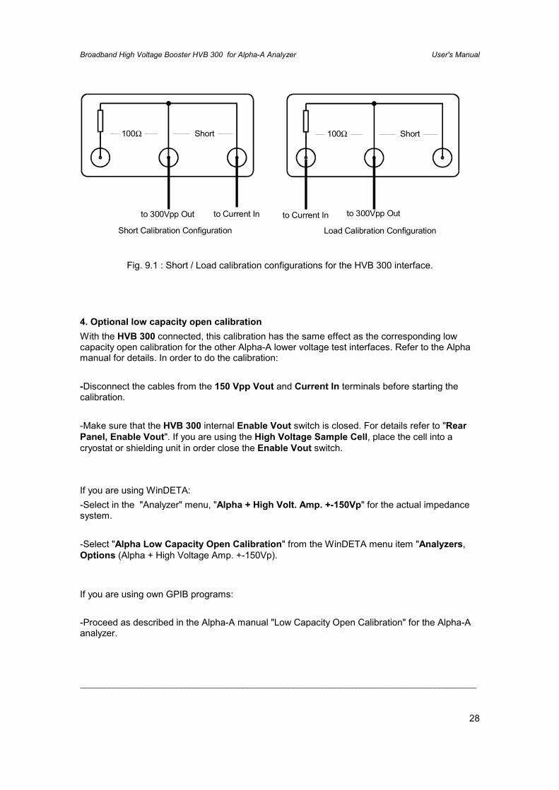
The calibration is started by the Alpha GPIB command sequences *RST, ZRUNCAL=SL_INIT,ZRUNCAL=SL_SHORT and ZRUNCAL=SL_100orthe WinDETA menu item "Analyzers, Options (Alpha Analyzer), “Alpha Load ShortCalibration”.After starting the calibration you will be asked by WinDETA or by the Alpha display for the GPIBcommand set to connect the short and load calibration standards to the HVB 300 as shownbelow.
Broadband High Voltage Booster HVB 300 for Alpha-A Analyzer User's Manual
_______________________________________________________________________________________________
28
100Ω100Ω ShortShort
to 300Vpp Outto 300Vpp Out to Current Into Current In
Load Calibration ConfigurationShort Calibration Configuration
Fig. 9.1 : Short / Load calibration configurations for the HVB 300 interface.
4. Optional low capacity open calibrationWith the HVB 300 connected, this calibration has the same effect as the corresponding lowcapacity open calibration for the other Alpha-A lower voltage test interfaces. Refer to the Alphamanual for details. In order to do the calibration:
-Disconnect the cables from the 150 Vpp Vout and Current In terminals before starting thecalibration.
-Make sure that the HVB 300 internal Enable Vout switch is closed. For details refer to "RearPanel, Enable Vout". If you are using the High Voltage Sample Cell, place the cell into acryostat or shielding unit in order close the Enable Vout switch.
If you are using WinDETA:-Select in the "Analyzer" menu, "Alpha + High Volt. Amp. +-150Vp" for the actual impedancesystem.
-Select "Alpha Low Capacity Open Calibration" from the WinDETA menu item "Analyzers,Options (Alpha + High Voltage Amp. +-150Vp).
If you are using own GPIB programs:
-Proceed as described in the Alpha-A manual "Low Capacity Open Calibration" for the Alpha-Aanalyzer.
Broadband High Voltage Booster HVB 300 for Alpha-A Analyzer User's Manual
_______________________________________________________________________________________________
29
11. Operating the Alpha-A with HVB 300 by GPIBcommands
Most of the commands are the same for operation of the Alpha-A analyzer with and without HVB300 connected. Nevertheless, the following differences apply with the HVB 300 connected.
-The MODE=VOLT command (gain phase mode) is not available and not allowed with theHVB 300 connected.
-The ACV=, DCE= and MST commands are only available after a system connections test withthe ZRUNCAL=CONCHECK command has been done. Details are described below.
If the Alpha-A mainframe is connected to the HVB 300 by the 25 pin Sub-D cable as describedin the "Rear Panel" chapter, the Analyzer will automatically enter the IMP_HV150 mode. Fordetails refer to the MODE= command in the Alpha-A manual. As a result the Alpha will adjust itscurrent and voltage ranges to the HVB 300.The ranges of the ACV= and DCV= commands which set the ac and dc voltage will be extendedand the HVB 300 amplification ratio will be taken into account so that the commands can beused as usual.E.g. DCV=50 will set 50V dc bias voltage at the 300 Vpp Vout socket. On the other hand, thevoltage at the GEN socket which acts as the voltage source for the HVB 300 will be about afactor 78 lower, which is the HVB 300 high voltage amplifier amplification.A similar situation applies for the V1 terminal which is driven by the output of the HVB 300internal voltage divider and therefore by a factor 78 below the voltage at the 300 Vpp Voutterminal. Anyhow, the Alpha will internally correct for this and display the voltage at the 300 VppVout terminal by internal multiplying the measured voltage at V1.
This concept will work as long as the external device setup and cabling as described in "SystemConnections for Measurements" is correctly realized.
On the other hand, problems may arise for an erroneous cabling setup different from theset-up described in the "System Connections for Measurements".
Warning : With connected HVB 300 this may result in set-ups which may be eitherdangerous for the operator as unexpected high voltages may be applied to unexpectedsystem parts or may damage the instrumentation by applying high voltage to low voltageterminals.
In order to avoid such situations for the device combnation Alpha-A and HVB 300, the Alphamainframe enters a special ZCON_TO_CHECK state =1 after power on or *RST where anyoutput voltage at the GEN and 300 Vpp Vout terminals and the ACV=, DCV= and MSTcommands are disabled for safety reasons.In order to switch the Alpha in the ZCON_TO_CHECK = 0 state where the previous limitationsdo not apply, a system connections test for the actual selected mode is required. The systemconnections test should be started by the ZRUNCAL=CONCHECK command after the proper
Broadband High Voltage Booster HVB 300 for Alpha-A Analyzer User's Manual
_______________________________________________________________________________________________
30
system setup was established as described in the "System Connections for Measurements"chapters.During the test a small voltage will be applied to the GEN socket which results in an notdangerous voltage at the 300 Vpp Vout socket if connected. The Alpha checks then the V1 andV2 terminals for proper voltages in order to make sure a proper system and cabling setup. If so,the system connections test is passed and ZCON_TO_CHECK state will change to 0 and theACV=, DCV= and MST commands will be available.
-The system connections test will be automatically applied at the beginning of any calibrationstarted by the ZRUNCAL= command.
-The system connections test is only required with the HVB 300 connected. The Alpha-Amainframe automatically detects the HVB 300 if connected by the 25 pin Sub-D cable asdescribed in the "Rear Panel" chapter.
Broadband High Voltage Booster HVB 300 for Alpha-A Analyzer User's Manual
_______________________________________________________________________________________________
31
12. Technical Data
Line voltage : 220 - 240 V ac, 50 - 60 Hz or110 V ac, 50 - 60 Hz (see instrument rear)
Power consumption : 50 W
EnvironmentOperating temperature : 0° to 40°CStorage temperature : -10° to 60°CSpecification limits : 20° to 30°C
Voltage Amplifier
Output impedance 200 Ω
Maximum output voltage 300 Vpp ac or dcfor f > 160 kHz linear decrease in ac amplitude to 60Vpp at 1 MHz
Maximum output current about +-70 mA, protected against permanent short to system ground
Frequency range DC to 1MHz.
Voltage amplification Vout/Vin About 78
Voltage divider
Voltage division Vout/V1 About 78
Current to voltage converterFrequency range
3 µHz .. 1 MHzCurrent ranges (rms)
40 mA, 15 mA, 1.5 mA, 150 µΑ, 15 µA, 1.5 µA,150 nA, 15 nA, 1.5 nA, 150 pA, 15 pA, 1.5 pA
Current resolution (reproducibility)+- 5 fA +-10-5 of current range

Broadband High Voltage Booster HVB 300 for Alpha-A Analyzer User's Manual
_______________________________________________________________________________________________
32
+-30 fA/Hz * frequency of measurementCapacity range
10-15 - 0.01 FResistance range
0.1 - 2.1015 ΩAccuracy in tan(δ) for capacitive samples:
+- 3.10-5 +- 10-3 of measured valuefor frequency between 1 Hz .. 100 kHz andsample capacity between 50 pF .. 2 nF
Reference capacitors63 build in low loss precision reference capacitors from 25 pF .. 2 nF
Broadband High Voltage Booster HVB 300 for Alpha-A Analyzer User's Manual
_______________________________________________________________________________________________
33
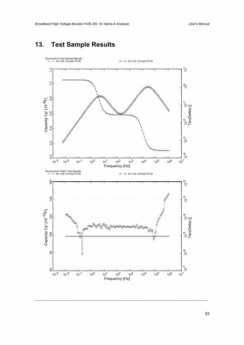
13. Test Sample Results
10-3 10-2 10-1 100 101 102 103 104 105 106 107
Frequency [Hz]
0.0
0.2
0.4
0.6
0.8
1.0
1.2
Cap
acity
Cp'
[10-9
F]
Novocontrol Test Sample Results AC Volt [Vrms]=70.00
10-4
10-3
10-2
10-1
100
101
Tan(
Del
ta) [
]
AC Volt [Vrms]=70.00
10-3 10-2 10-1 100 101 102 103 104 105 106 107
Frequency [Hz]
6080
100
120
140
160
Cap
acity
Cp'
[10-1
2 F]
Novocontrol 100pF Test Sample AC Volt [Vrms]=70.00
10-7
10-6
10-5
10-4
10-3
10-2
Tan(
Del
ta) [
]
AC Volt [Vrms]=70.00