Techtop Wiring Diagrams - Techtop Canada Inc. diagram (tcp)… · Techtop Wiring Diagrams ... If...
1
www.mldltd.com Techtop Wiring Diagrams NEMA Three Phase TCP Wiring Connections 3 Phase YY/Y 9 Lead 230/460V 1 2 3 7 8 9 4 5 6 1 2 3 7 8 9 4 5 6 Connection Diagrams Low Voltage High Voltage Wire Color T1, T4 Blue T5, T2 White T6, T3 Orange T7 Yellow T8 Black T9 Red 3 Phase ΔΔ/Δ 12 Lead 230/460V 1 2 3 12 10 11 Connection Diagrams Low Voltage High Voltage Wire Color T1, T4 Blue T5, T2 White T3, T6 Orange T7, T10 Yellow T8, T11 Black T9, T12 Red 6 4 5 7 8 9 1 2 3 12 10 11 6 4 5 7 8 9 215T Frame and Smaller 254T Frame and Larger Wiring Your Techtop Motor Connect the motor as shown in the connection diagram on the motor nameplate. Be sure to identify the proper wiring diagram for the motor you are installing. If you have difficulty determining the proper wiring diagram for your motor, please contact Maple Leaf Drives Ltd. for as- sistance. If this motor is installed as part of a motor control drive system, connect and protect the motor according to the control manufacturer’s diagram. When using AC motors with frequency inverters, be certain that the motors maximum speed rating is not exceeded. The wiring, fusing and grounding must comply with the National Elec- trical Code or IEC and local codes. Note: If improper rotation direction is detrimental to the load, check the rotation or ‘bump’ the motor prior to coupling the load to the motor shaft. When the motor is coupled to the load and started, it should start quickly and run smoothly. If not, stop the motor immediately and determine the cause. Possible causes are: low voltage at the motor, motor connections are not correct or the load is too heavy. Check the motor current after a few minutes of operation and compare the measured current with the nameplate rating. 3 Phase Single Voltage 460V or 575V 1 2 3 1 2 3 6 4 5 Connection Diagrams 215T and Smaller Y 254T and Larger Δ Wire Color T1, T4 Blue T5, T2 White T6, T3 Orange 3 Phase Single Voltage Connections WARNING: Do not touch electrical connections unless you first ensure that power has been disconnected. Please refer to: OSHA standard 1910.147 titled: The Control of Hazardous energy (lockout/tag-out). WARNING: Surface temperatures of motor enclosures may reach temperatures which can cause discomfort or injury to personnel coming in contact with hot surfaces. Protection should be provided by the user to protect against accidental contact with hot surfaces. Failure to observe this precaution- could result in bodily injury. WARNING: Surface temperatures of motor enclosures may reach temperatures which can cause discomfort or injury to personnel coming in contact with hot surfaces. Protection should be provided by the user to protect against accidental contact with hot surfaces. Failure to observe this precaution- could result in bodily injury.
-
Upload
hoangduong -
Category
Documents
-
view
213 -
download
0
Transcript of Techtop Wiring Diagrams - Techtop Canada Inc. diagram (tcp)… · Techtop Wiring Diagrams ... If...
www.mldltd.com
Techtop Wiring DiagramsNEMA Three Phase TCP Wiring Connections
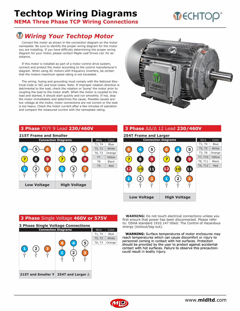
3 Phase YY/Y 9 Lead 230/460V
1 2 3
7 8 9
4 5 6
1 2 3
7 8 9
4 5 6
Connection Diagrams
Low Voltage High Voltage
Wire ColorT1, T4 BlueT5, T2 WhiteT6, T3 Orange
T7 YellowT8 BlackT9 Red
3 Phase ΔΔ/Δ 12 Lead 230/460V
1 2 3
12 10 11
Connection Diagrams
Low Voltage High Voltage
Wire ColorT1, T4 BlueT5, T2 WhiteT3, T6 OrangeT7, T10 YellowT8, T11 BlackT9, T12 Red
6 4 5
7 8 9
1 2 3
12 10 11
6 4 5
7 8 9
215T Frame and Smaller 254T Frame and Larger
Wiring Your Techtop Motor Connect the motor as shown in the connection diagram on the motor nameplate. Be sure to identify the proper wiring diagram for the motor you are installing. If you have difficulty determining the proper wiring diagram for your motor, please contact Maple Leaf Drives Ltd. for as-sistance.
If this motor is installed as part of a motor control drive system, connect and protect the motor according to the control manufacturer’s diagram. When using AC motors with frequency inverters, be certain that the motors maximum speed rating is not exceeded.
The wiring, fusing and grounding must comply with the National Elec-trical Code or IEC and local codes. Note: If improper rotation direction is detrimental to the load, check the rotation or ‘bump’ the motor prior to coupling the load to the motor shaft. When the motor is coupled to the load and started, it should start quickly and run smoothly. If not, stop the motor immediately and determine the cause. Possible causes are: low voltage at the motor, motor connections are not correct or the load is too heavy. Check the motor current after a few minutes of operation and compare the measured current with the nameplate rating.
3 Phase Single Voltage 460V or 575V
1 2 31 2 3
6 4 5
Connection Diagrams
215T and Smaller Y 254T and Larger Δ
Wire ColorT1, T4 BlueT5, T2 WhiteT6, T3 Orange
3 Phase Single Voltage Connections
WARNING: Do not touch electrical connections unless you first ensure that power has been disconnected. Please refer to: OSHA standard 1910.147 titled: The Control of Hazardous energy (lockout/tag-out).
WARNING: Surface temperatures of motor enclosures may reach temperatures which can cause discomfort or injury to personnel coming in contact with hot surfaces. Protection should be provided by the user to protect against accidental contact with hot surfaces. Failure to observe this precaution-could result in bodily injury.
WARNING: Surface temperatures of motor enclosures may reach temperatures which can cause discomfort or injury to personnel coming in contact with hot surfaces. Protection should be provided by the user to protect against accidental contact with hot surfaces. Failure to observe this precaution-could result in bodily injury.