Technical application guide Colormix Tunable White · cd/klm η= 100% 15° 30° 105° 90° 75° ......
27
www.osram.de www.osram.de www.osram.com JANUARY 2015 Technical application guide DRAGONchain ® Colormix DRAGONchain ® Tunable White
-
Upload
truonghanh -
Category
Documents
-
view
221 -
download
0
Transcript of Technical application guide Colormix Tunable White · cd/klm η= 100% 15° 30° 105° 90° 75° ......
www.osram.dewww.osram.dewww.osram.com
JANUARY
2015
Technical application guideDRAGONchain® ColormixDRAGONchain® Tunable White
2
CONTENTS
CONTENTS
1. Product overview: DRAGONchain® LED modules 3
1.1. DRAGONchain® Tunable White (DC24B-TW) 3
1.2. DRAGONchain® Colormix (DC24B-RGBW) 4
1.3. System information 5
1.3.1. Technical data 5
1.3.2. Nomenclature and marking 6
2. Product overview: OPTOTRONIC® electronic devices 7
2.1. OPTOTRONIC® power supplies 7
2.1.1. OT 50/220-240/24 7
2.1.2. OT 75/220-240/24 7
2.1.3. OT 80/220-240/24 P 8
2.1.4. OT 120/220-240/24 P 8
2.1.5. OT 240/220-240/24 P 8
2.2. OPTOTRONIC® all-in-one devices 9
2.2.1. OTi DALI 75/220-240/24 1-4 CH 9
2.2.2. OT EASY 80 9
2.3. System information 10
2.3.1. Technical data 10
3. System combination 11
3.1. System overview: LED chains and control devices 11
3.2. System overview: All-in-one devices – LED chains 11
3.3. Recommended solutions 12
4. Mounting instructions 15
4.1. General information 15
4.2. Assembly of DC24B-XX modules in a mounting profi le 15
4.3. Fastening cables with mounting clips 16
4.4. Disassembly of the mounting clips 17
4.5. Mounting on a heat sink 18
4.6. Assembly of the mounting profi le with mounting brackets 19
4.7. Assembly of the mounting profi le on a metal surface 20
5. Application overview 21
5.1. Luminance levels and minimum depths 21
6. Thermal properties 23
6.1. Casing temperature at the Tc point 23
6.2. Measuring the Tc temperature 23
7. Norms and standards 24
7.1. Norms and standards for LED modules 24
7.2. Norms and standards for power supplies 24
8. Notes 25
8.1. General notes 25
8.2. Guarantee information 25
8.3. Safety information 25
9. Further information 26
Please note:All information in this guide has been prepared with great
care. OSRAM, however, does not accept liability for
possible errors, changes and/or omissions. Please check
www.osram.com or contact your sales partner for an up-
dated copy of this guide. This technical application guide
is for information purposes only and aims to support you
in tackling the challenges and taking full advantage of all
opportunities the technology has to offer. Please note that
this guide is based on own measurements, tests, specifi c
parameters and assumptions. Individual applications may
not be covered and need different handling. Responsibility
and testing obligations remain with the luminaire manufac-
turer/OEM/application planner.
3
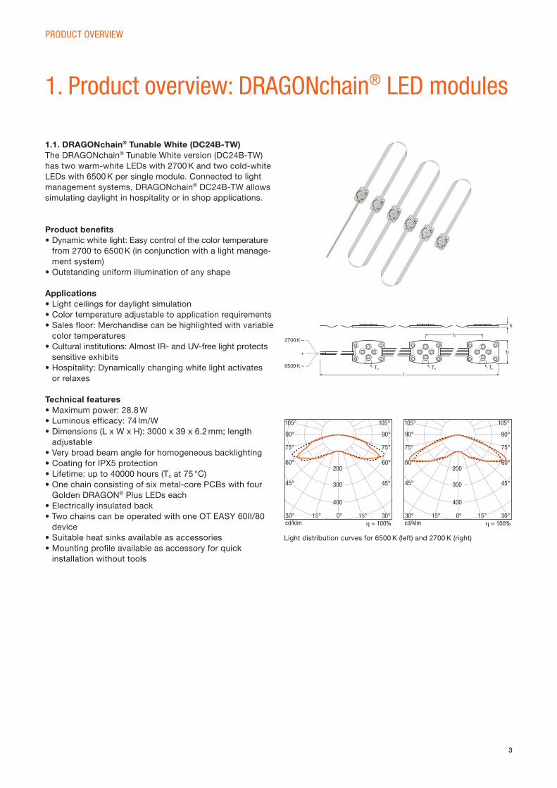
1.1. DRAGONchain® Tunable White (DC24B-TW)The DRAGONchain® Tunable White version (DC24B-TW)
has two warm-white LEDs with 2700 K and two cold-white
LEDs with 6500 K per single module. Connected to light
management systems, DRAGONchain® DC24B-TW allows
simulating daylight in hospitality or in shop applications.
Product benefi ts• Dynamic white light: Easy control of the color temperature
from 2700 to 6500 K (in conjunction with a light manage-
ment system)
• Outstanding uniform illumination of any shape
Applications• Light ceilings for daylight simulation
• Color temperature adjustable to application requirements
• Sales fl oor: Merchandise can be highlighted with variable
color temperatures
• Cultural institutions: Almost IR- and UV-free light protects
sensitive exhibits
• Hospitality: Dynamically changing white light activates
or relaxes
Technical features• Maximum power: 28.8 W
• Luminous effi cacy: 74 lm/W
• Dimensions (L x W x H): 3000 x 39 x 6.2 mm; length
adjustable
• Very broad beam angle for homogeneous backlighting
• Coating for IPX5 protection
• Lifetime: up to 40000 hours (Tc at 75 °C)
• One chain consisting of six metal-core PCBs with four
Golden DRAGON® Plus LEDs each
• Electrically insulated back
• Two chains can be operated with one OT EASY 60II/80
device
• Suitable heat sinks available as accessories
• Mounting profi le available as accessory for quick
installation without tools
PRODUCT OVERVIEW
1. Product overview: DRAGONchain® LED modules
h
l
b
Tc Tc
2700 K –
6500 K –
+
Tc
l1
Light distribution curves for 6500 K (left) and 2700 K (right)
cd/klm η = 100%15° 30°
105°
90°
75°
60°
45°
30° 15° 0°
105°
75°
90°
60°
45°
200
300
400
cd/klm η = 100%15° 30°
105°
90°
75°
60°
45°
30° 15° 0°
105°
75°
90°
60°
45°
200
300
400
4
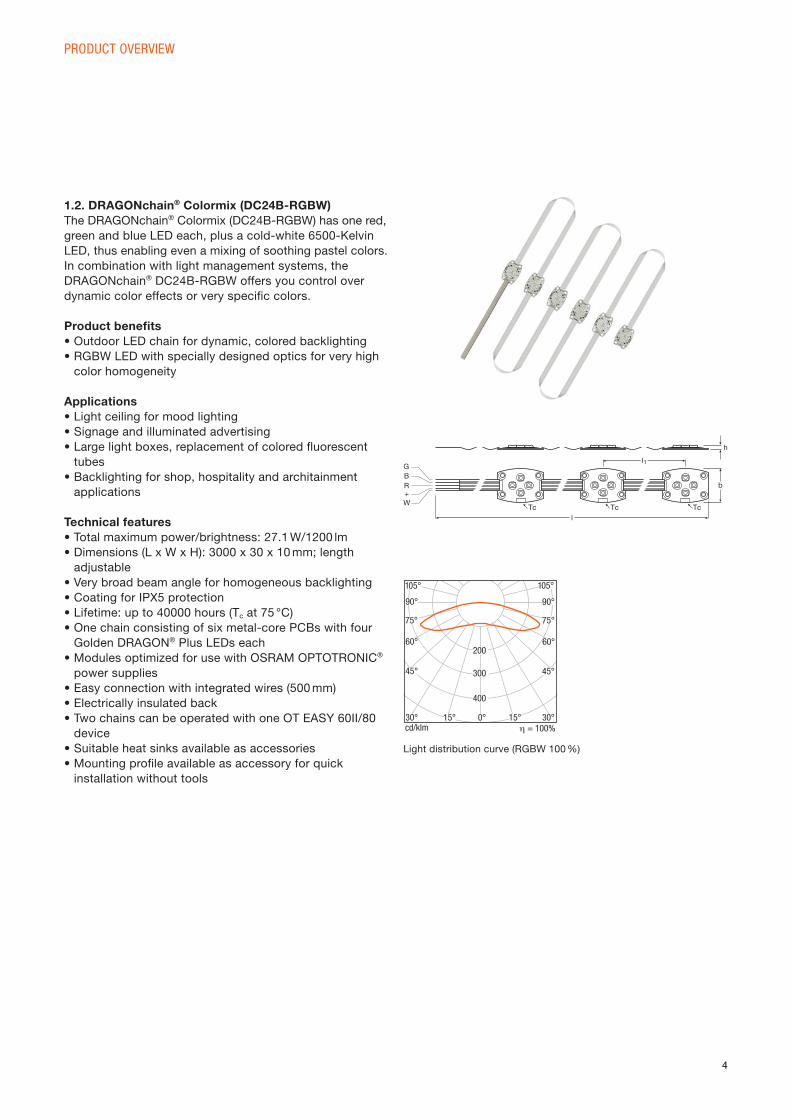
Light distribution curve (RGBW 100 %)
1.2. DRAGONchain® Colormix (DC24B-RGBW)The DRAGONchain® Colormix (DC24B-RGBW) has one red,
green and blue LED each, plus a cold-white 6500-Kelvin
LED, thus enabling even a mixing of soothing pastel colors.
In combination with light management systems, the
DRAGONchain® DC24B-RGBW offers you control over
dynamic color effects or very specifi c colors.
Product benefi ts• Outdoor LED chain for dynamic, colored backlighting
• RGBW LED with specially designed optics for very high
color homogeneity
Applications• Light ceiling for mood lighting
• Signage and illuminated advertising
• Large light boxes, replacement of colored fl uorescent
tubes
• Backlighting for shop, hospitality and architainment
applications
Technical features• Total maximum power/brightness: 27.1 W/1200 lm
• Dimensions (L x W x H): 3000 x 30 x 10 mm; length
adjustable
• Very broad beam angle for homogeneous backlighting
• Coating for IPX5 protection
• Lifetime: up to 40000 hours (Tc at 75 °C)
• One chain consisting of six metal-core PCBs with four
Golden DRAGON® Plus LEDs each
• Modules optimized for use with OSRAM OPTOTRONIC®
power supplies
• Easy connection with integrated wires (500 mm)
• Electrically insulated back
• Two chains can be operated with one OT EASY 60II/80
device
• Suitable heat sinks available as accessories
• Mounting profi le available as accessory for quick
installation without tools
PRODUCT OVERVIEW
h
l
b
Tc Tc Tc
l1GBR+W
cd/klm η = 100%15° 30°
105°
90°
75°
60°
45°
30° 15° 0°
105°
75°
90°
60°
45°
200
300
400
5
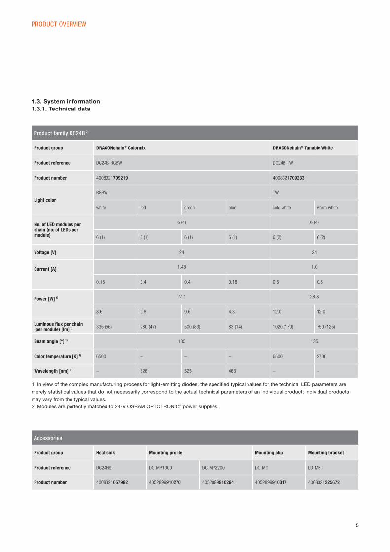
1.3. System information1.3.1. Technical data
PRODUCT OVERVIEW
Product family DC24B 2)
Product group DRAGONchain® Colormix DRAGONchain® Tunable White
Product reference DC24B-RGBW DC24B-TW
Product number 4008321709219 4008321709233
Light color
RGBW TW
white red green blue cold white warm white
No. of LED modules per chain (no. of LEDs per module)
6 (4) 6 (4)
6 (1) 6 (1) 6 (1) 6 (1) 6 (2) 6 (2)
Voltage [V] 24 24
Current [A] 1.48 1.0
0.15 0.4 0.4 0.18 0.5 0.5
Power [W] 1) 27.1 28.8
3.6 9.6 9.6 4.3 12.0 12.0
Luminous fl ux per chain (per module) [lm] 1) 335 (56) 280 (47) 500 (83) 83 (14) 1020 (170) 750 (125)
Beam angle [°] 1) 135 135
Color temperature [K] 1) 6500 – – – 6500 2700
Wavelength [nm] 1) – 626 525 468 – –
1) In view of the complex manufacturing process for light-emitting diodes, the specifi ed typical values for the technical LED parameters are
merely statistical values that do not necessarily correspond to the actual technical parameters of an individual product; individual products
may vary from the typical values.
2) Modules are perfectly matched to 24-V OSRAM OPTOTRONIC® power supplies.
Accessories
Product group Heat sink Mounting profi le Mounting clip Mounting bracket
Product reference DC24HS DC-MP1000 DC-MP2200 DC-MC LD-MB
Product number 4008321657992 4052899910270 4052899910294 4052899910317 4008321225672
6
Made in ItalyA A33 346 00 72
DC24B-RGBWDRAGONchain Colormix
24V(DC) 27W
Made in ItalyA A34 299 00 72
DC24B-TWDRAGONchain Tunable White
24V(DC) 24W
PRODUCT OVERVIEW
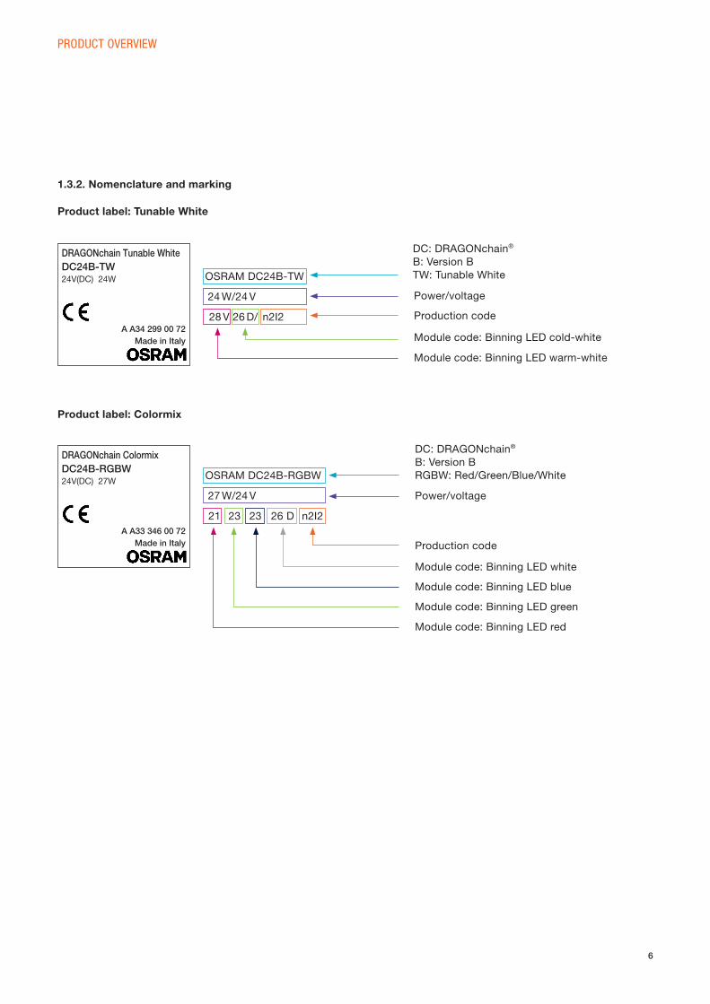
1.3.2. Nomenclature and marking
Product label: Tunable White
Product label: Colormix
OSRAM DC24B-TW
OSRAM DC24B-RGBW
24 W/24 V
27 W/24 V
28 V 26 D/
21 23 23 26 D
n2I2
n2I2
DC: DRAGONchain®
B: Version B
TW: Tunable White
DC: DRAGONchain®
B: Version B
RGBW: Red/Green/Blue/White
Module code: Binning LED cold-white
Module code: Binning LED warm-white
Production code
Module code: Binning LED white
Module code: Binning LED blue
Module code: Binning LED red
Module code: Binning LED green
Power/voltage
Power/voltage
Production code
7
PRODUCT OVERVIEW
2. Product overview: OPTOTRONIC® electronic devices
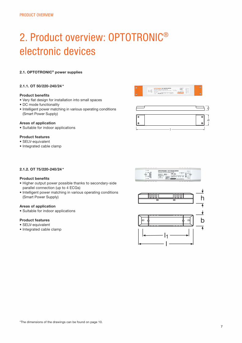
2.1.1. OT 50/220-240/24 *
Product benefi ts• Very fl at design for installation into small spaces
• DC mode functionality
• Intelligent power matching in various operating conditions
(Smart Power Supply)
Areas of application• Suitable for indoor applications
Product features• SELV-equivalent
• Integrated cable clamp
2.1. OPTOTRONIC® power supplies
2.1.2. OT 75/220-240/24 *
Product benefi ts• Higher output power possible thanks to secondary-side
parallel connection (up to 4 ECGs)
• Intelligent power matching in various operating conditions
(Smart Power Supply)
Areas of application• Suitable for indoor applications
Product features• SELV-equivalent
• Integrated cable clamp
l1l
h
b
*The dimensions of the drawings can be found on page 10.
bh
l
8
PRODUCT OVERVIEW
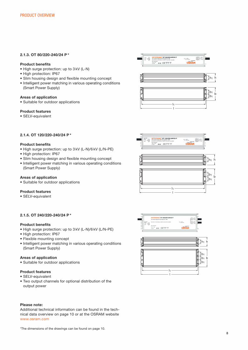
2.1.3. OT 80/220-240/24 P *
Product benefi ts• High surge protection: up to 3 kV (L-N)
• High protection: IP67
• Slim housing design and fl exible mounting concept
• Intelligent power matching in various operating conditions
(Smart Power Supply)
Areas of application• Suitable for outdoor applications
Product features• SELV-equivalent
2.1.4. OT 120/220-240/24 P *
Product benefi ts• High surge protection: up to 3 kV (L-N)/6 kV (L/N-PE)
• High protection: IP67
• Slim housing design and fl exible mounting concept
• Intelligent power matching in various operating conditions
(Smart Power Supply)
Areas of application• Suitable for outdoor applications
Product features• SELV-equivalent
2.1.5. OT 240/220-240/24 P *
Product benefi ts• High surge protection: up to 3 kV (L-N)/6 kV (L/N-PE)
• High protection: IP67
• Flexible mounting concept
• Intelligent power matching in various operating conditions
(Smart Power Supply)
Areas of application• Suitable for outdoor applications
Product features• SELV-equivalent
• Two output channels for optional distribution of the
output power
b
h
b1b1
b1
h1
ll1
Please note:Additional technical information can be found in the tech-
nical data overview on page 10 or at the OSRAM website
www.osram.com
*The dimensions of the drawings can be found on page 10.
b
h
b1
h1
b1
ll1
b
h
b1
h1
b1
ll1
9
PRODUCT OVERVIEW
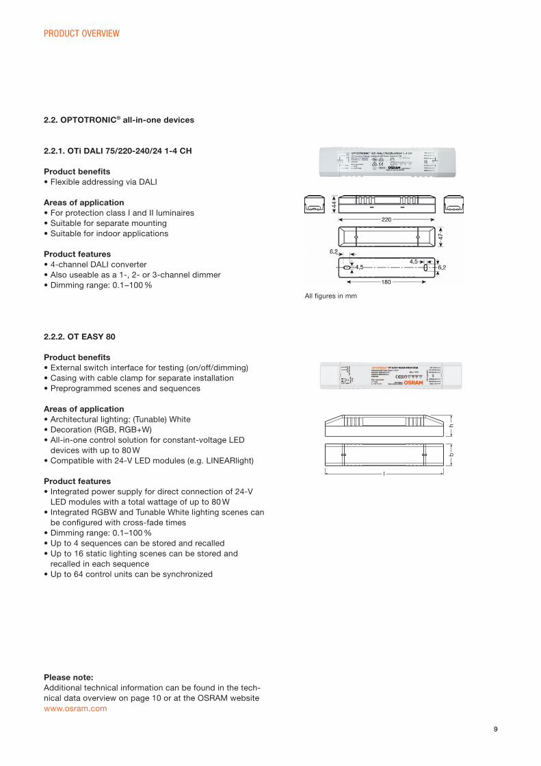
2.2.1. OTi DALI 75/220-240/24 1-4 CH
Product benefi ts• Flexible addressing via DALI
Areas of application• For protection class I and II luminaires
• Suitable for separate mounting
• Suitable for indoor applications
Product features• 4-channel DALI converter
• Also useable as a 1-, 2- or 3-channel dimmer
• Dimming range: 0.1–100 %
2.2. OPTOTRONIC® all-in-one devices
2.2.2. OT EASY 80
Product benefi ts• External switch interface for testing (on/off/dimming)
• Casing with cable clamp for separate installation
• Preprogrammed scenes and sequences
Areas of application• Architectural lighting: (Tunable) White
• Decoration (RGB, RGB+W)
• All-in-one control solution for constant-voltage LED
devices with up to 80 W
• Compatible with 24-V LED modules (e.g. LINEARlight)
Product features• Integrated power supply for direct connection of 24-V
LED modules with a total wattage of up to 80 W
• Integrated RGBW and Tunable White lighting scenes can
be confi gured with cross-fade times
• Dimming range: 0.1–100 %
• Up to 4 sequences can be stored and recalled
• Up to 16 static lighting scenes can be stored and
recalled in each sequence
• Up to 64 control units can be synchronized
Please note:Additional technical information can be found in the tech-
nical data overview on page 10 or at the OSRAM website
www.osram.com
All fi gures in mm
bh
l
10
PRODUCT OVERVIEW
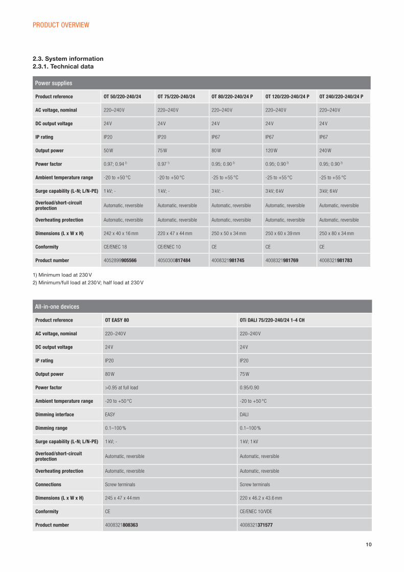
2.3. System information2.3.1. Technical data
Power supplies
Product reference OT 50/220-240/24 OT 75/220-240/24 OT 80/220-240/24 P OT 120/220-240/24 P OT 240/220-240/24 P
AC voltage, nominal 220–240 V 220–240 V 220–240 V 220–240 V 220–240 V
DC output voltage 24 V 24 V 24 V 24 V 24 V
IP rating IP20 IP20 IP67 IP67 IP67
Output power 50 W 75 W 80 W 120 W 240 W
Power factor 0.97; 0.94 2) 0.97 1) 0.95; 0.90 2) 0.95; 0.90 2) 0.95; 0.90 2)
Ambient temperature range -20 to +50 °C -20 to +50 °C -25 to +55 °C -25 to +55 °C -25 to +55 °C
Surge capability (L-N; L/N-PE) 1 kV; - 1 kV; - 3 kV; - 3 kV; 6 kV 3 kV; 6 kV
Overload/short-circuit protection
Automatic, reversible Automatic, reversible Automatic, reversible Automatic, reversible Automatic, reversible
Overheating protection Automatic, reversible Automatic, reversible Automatic, reversible Automatic, reversible Automatic, reversible
Dimensions (L x W x H) 242 x 40 x 16 mm 220 x 47 x 44 mm 250 x 50 x 34 mm 250 x 60 x 39 mm 250 x 80 x 34 mm
Conformity CE/ENEC 18 CE/ENEC 10 CE CE CE
Product number 4052899905566 4050300817484 4008321981745 4008321981769 4008321981783
1) Minimum load at 230 V
2) Minimum/full load at 230 V; half load at 230 V
All-in-one devices
Product reference OT EASY 80 OTi DALI 75/220-240/24 1-4 CH
AC voltage, nominal 220–240 V 220–240 V
DC output voltage 24 V 24 V
IP rating IP20 IP20
Output power 80 W 75 W
Power factor >0.95 at full load 0.95/0.90
Ambient temperature range -20 to +50 °C -20 to +50 °C
Dimming interface EASY DALI
Dimming range 0.1–100 % 0.1–100 %
Surge capability (L-N; L/N-PE) 1 kV; - 1 kV; 1 kV
Overload/short-circuitprotection
Automatic, reversible Automatic, reversible
Overheating protection Automatic, reversible Automatic, reversible
Connections Screw terminals Screw terminals
Dimensions (L x W x H) 245 x 47 x 44 mm 220 x 46.2 x 43.6 mm
Conformity CE CE/ENEC 10/VDE
Product number 4008321808363 4008321371577
11
SYSTEM COMBINATION
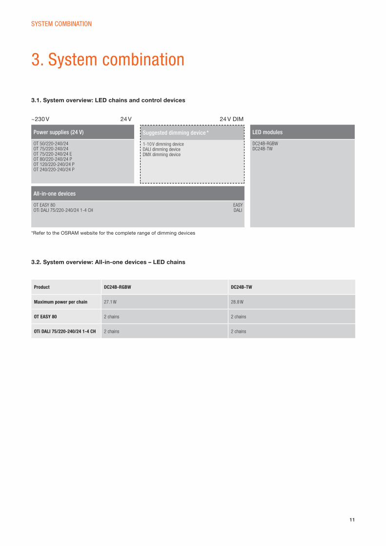
3. System combination
3.1. System overview: LED chains and control devices
3.2. System overview: All-in-one devices – LED chains
Power supplies (24 V)
OT 50/220-240/24 OT 75/220-240/24OT 75/220-240/24 EOT 80/220-240/24 POT 120/220-240/24 POT 240/220-240/24 P
All-in-one devices
OT EASY 80 EASYOTi DALI 75/220-240/24 1-4 CH DALI
LED modules
DC24B-RGBWDC24B-TW
~230 V 24 V 24 V DIM
Product DC24B-RGBW DC24B-TW
Maximum power per chain 27.1 W 28.8 W
OT EASY 80 2 chains 2 chains
OTi DALI 75/220-240/24 1-4 CH 2 chains 2 chains
Suggested dimming device *
1-10 V dimming deviceDALI dimming deviceDMX dimming device
*Refer to the OSRAM website for the complete range of dimming devices
12
SYSTEM COMBINATION
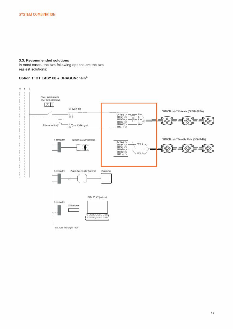
3.3. Recommended solutionsIn most cases, the two following options are the two
easiest solutions:
Option 1: OT EASY 80 + DRAGONchain®
PE N L
Power switch and/or timer switch (optional)
OT EASY 80DRAGONchain® Colormix (DC24B-RGBW)
DRAGONchain® Tunable White (DC24B-TW)
External switch EASY signal
24 V (+) GB
2700 K –
+
6500 K –
R+W
24 V (+)
CH1 (R-)
CH1 (R-)
CH3 (B-)
CH3 (B-)
CH4 (W-)
CH4 (W-)
GND (-)
GND (-)
CH2 (G-)
CH2 (G-)
Y-connector
Y-connector
Y-connectorUSB adapter
Max. total line length 100 m
EASY PC KIT (optional)
Infrared receiver (optional)
Pushbutton coupler (optional) Pushbutton
LN
13
SYSTEM COMBINATION
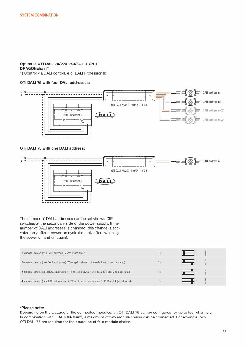
Option 2: OTi DALI 75/220-240/24 1-4 CH + DRAGONchain®
1) Control via DALI control, e.g. DALI Professional:
OTi DALI 75 with four DALI addresses:
The number of DALI addresses can be set via two DIP
switches at the secondary side of the power supply. If the
number of DALI addresses is changed, this change is acti-
vated only after a power-on cycle (i.e. only after switching
the power off and on again).
OTi DALI 75 with one DALI address:
1-channel device (one DALI address): 75 W at channel 1 On21
2-channel device (two DALI addresses): 75 W split between channels 1 and 2 (unbalanced) On21
3-channel device (three DALI addresses): 75 W split between channels 1, 2 and 3 (unbalanced) On21
4-channel device (four DALI addresses): 75 W split between channels 1, 2, 3 and 4 (unbalanced) On21
DALI address n
DALI address n+1
DALI address n+2 *
DALI address n+3 *
DALI Professional
DA
OTi DALI 75/220-240/24 1-4 CH
LN
DALI address n
DALI Professional
OTi DALI 75/220-240/24 1-4 CH
LN
DA
*Please note:Depending on the wattage of the connected modules, an OTi DALI 75 can be confi gured for up to four channels.
In combination with DRAGONchain®, a maximum of two module chains can be connected. For example, two
OTi DALI 75 are required for the operation of four module chains.
14
SYSTEM COMBINATION
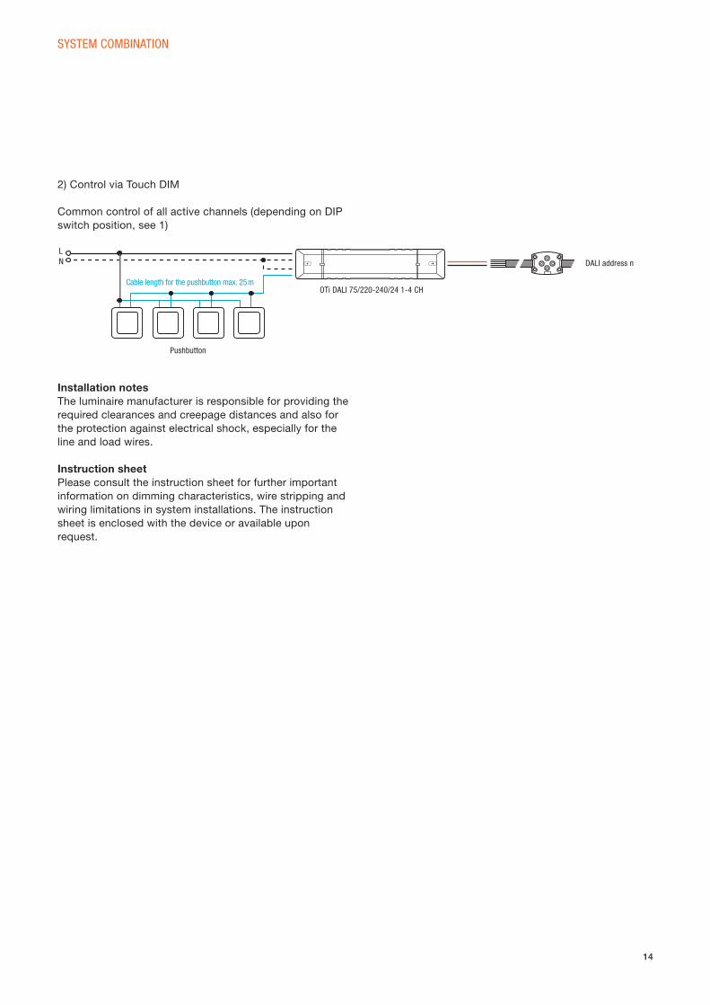
2) Control via Touch DIM
Common control of all active channels (depending on DIP
switch position, see 1)
Installation notesThe luminaire manufacturer is responsible for providing the
required clearances and creepage distances and also for
the protection against electrical shock, especially for the
line and load wires.
Instruction sheetPlease consult the instruction sheet for further important
information on dimming characteristics, wire stripping and
wiring limitations in system installations. The instruction
sheet is enclosed with the device or available upon
request.
Pushbutton
OTi DALI 75/220-240/24 1-4 CH
LN
Cable length for the pushbutton max. 25 m
DALI address n
15
4. Mounting instructions
MOUNTING INSTRUCTIONS
4.1. General information • During the entire installation process, the personnel must be ESD-protected.
• For effective thermal management, the distance between two LED modules has to be at least 100 mm at a
Ta (ambient temperature) of 25 °C max.
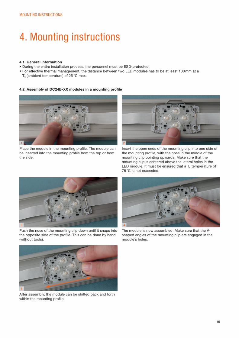
4.2. Assembly of DC24B-XX modules in a mounting profi le
Place the module in the mounting profi le. The module can
be inserted into the mounting profi le from the top or from
the side.
Insert the open ends of the mounting clip into one side of
the mounting profi le, with the nose in the middle of the
mounting clip pointing upwards. Make sure that the
mounting clip is centered above the lateral holes in the
LED module. It must be ensured that a Tc temperature of
75 °C is not exceeded.
1 2
Push the nose of the mounting clip down until it snaps into
the opposite side of the profi le. This can be done by hand
(without tools).
The module is now assembled. Make sure that the V-
shaped angles of the mounting clip are engaged in the
module’s holes.
After assembly, the module can be shifted back and forth
within the mounting profi le.
3 4
5
16
MOUNTING INSTRUCTIONS
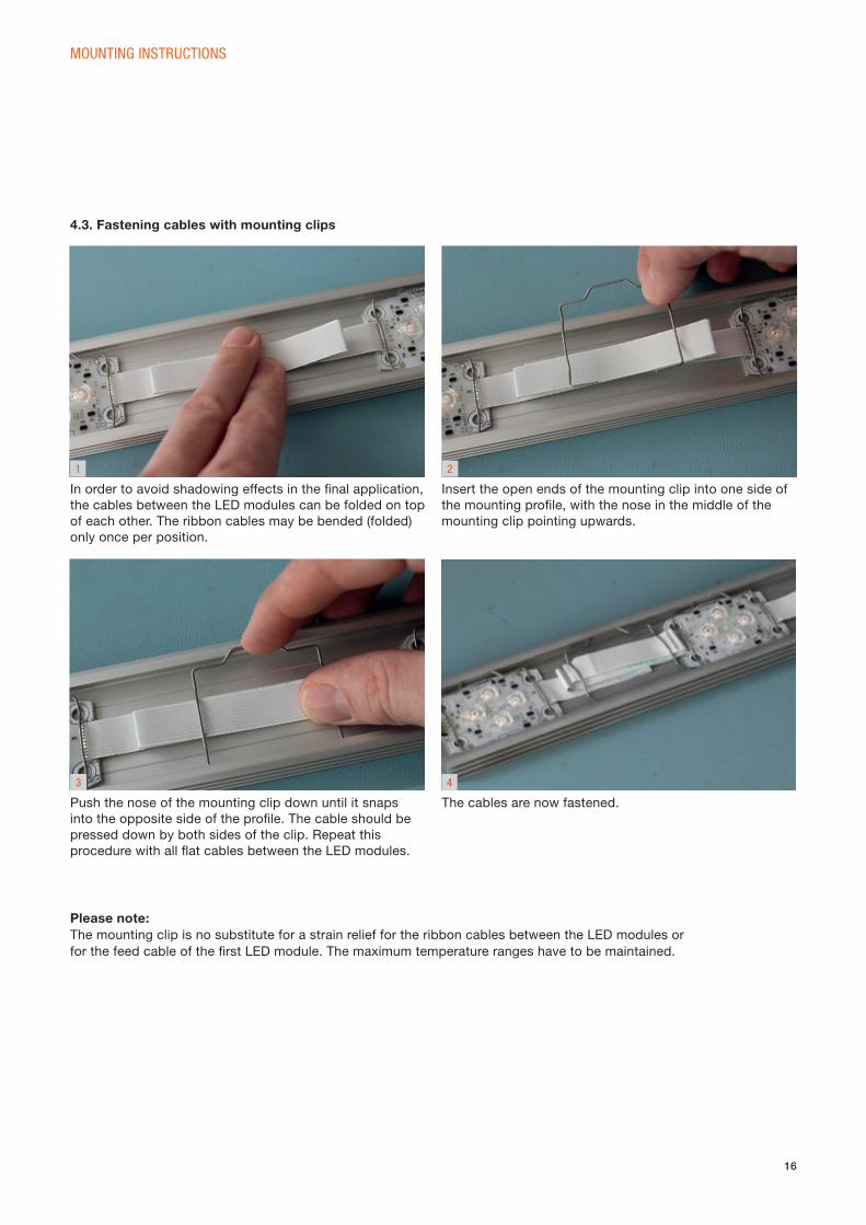
4.3. Fastening cables with mounting clips
1 2
3
In order to avoid shadowing effects in the fi nal application,
the cables between the LED modules can be folded on top
of each other. The ribbon cables may be bended (folded)
only once per position.
Insert the open ends of the mounting clip into one side of
the mounting profi le, with the nose in the middle of the
mounting clip pointing upwards.
Push the nose of the mounting clip down until it snaps
into the opposite side of the profi le. The cable should be
pressed down by both sides of the clip. Repeat this
procedure with all fl at cables between the LED modules.
4
The cables are now fastened.
Please note: The mounting clip is no substitute for a strain relief for the ribbon cables between the LED modules or
for the feed cable of the fi rst LED module. The maximum temperature ranges have to be maintained.

17
MOUNTING INSTRUCTIONS
1 2
3
Grasp the mounting clip with long-nosed pliers, as shown
in fi gure 1.
Carefully pull the nose of the mounting clip out of the
profi le.
The mounting clip is now disassembled. Please check the
clip for deformations before using it again.
4.4. Disassembly of the mounting clips
18
MOUNTING INSTRUCTIONS
1
3
5
2
4
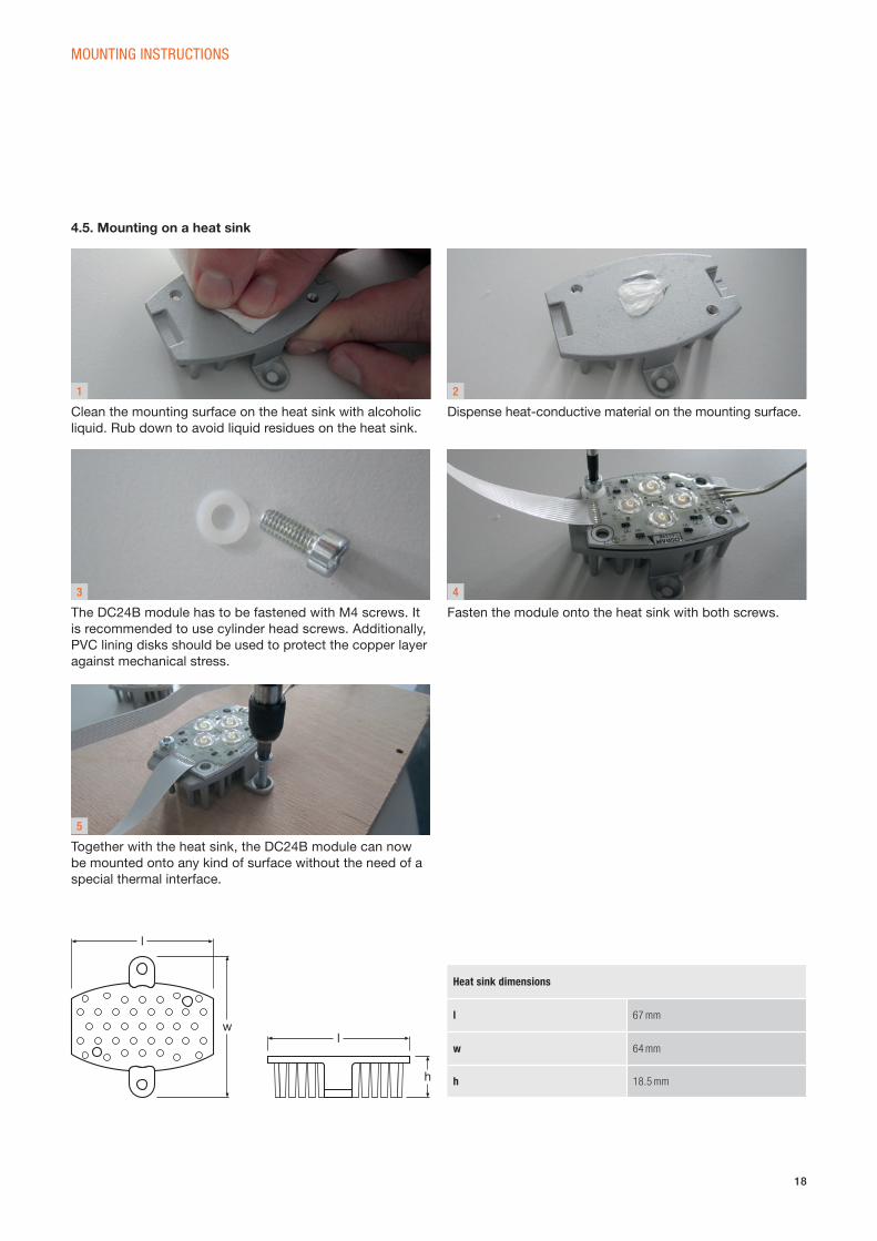
4.5. Mounting on a heat sink
Heat sink dimensions
l 67 mm
w 64 mm
h 18.5 mm
w
h
l
l
Clean the mounting surface on the heat sink with alcoholic
liquid. Rub down to avoid liquid residues on the heat sink.
The DC24B module has to be fastened with M4 screws. It
is recommended to use cylinder head screws. Additionally,
PVC lining disks should be used to protect the copper layer
against mechanical stress.
Together with the heat sink, the DC24B module can now
be mounted onto any kind of surface without the need of a
special thermal interface.
Fasten the module onto the heat sink with both screws.
Dispense heat-conductive material on the mounting surface.
19
1 2
3
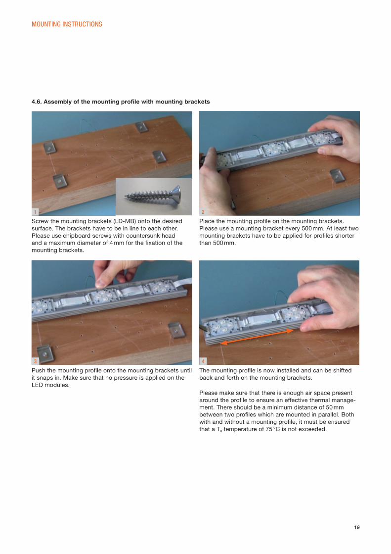
Screw the mounting brackets (LD-MB) onto the desired
surface. The brackets have to be in line to each other.
Please use chipboard screws with countersunk head
and a maximum diameter of 4 mm for the fi xation of the
mounting brackets.
Place the mounting profi le on the mounting brackets.
Please use a mounting bracket every 500 mm. At least two
mounting brackets have to be applied for profi les shorter
than 500 mm.
Push the mounting profi le onto the mounting brackets until
it snaps in. Make sure that no pressure is applied on the
LED modules.
4.6. Assembly of the mounting profi le with mounting brackets
4
The mounting profi le is now installed and can be shifted
back and forth on the mounting brackets.
Please make sure that there is enough air space present
around the profi le to ensure an effective thermal manage-
ment. There should be a minimum distance of 50 mm
between two profi les which are mounted in parallel. Both
with and without a mounting profi le, it must be ensured
that a Tc temperature of 75 °C is not exceeded.
MOUNTING INSTRUCTIONS
20
MOUNTING INSTRUCTIONS
1 2
3
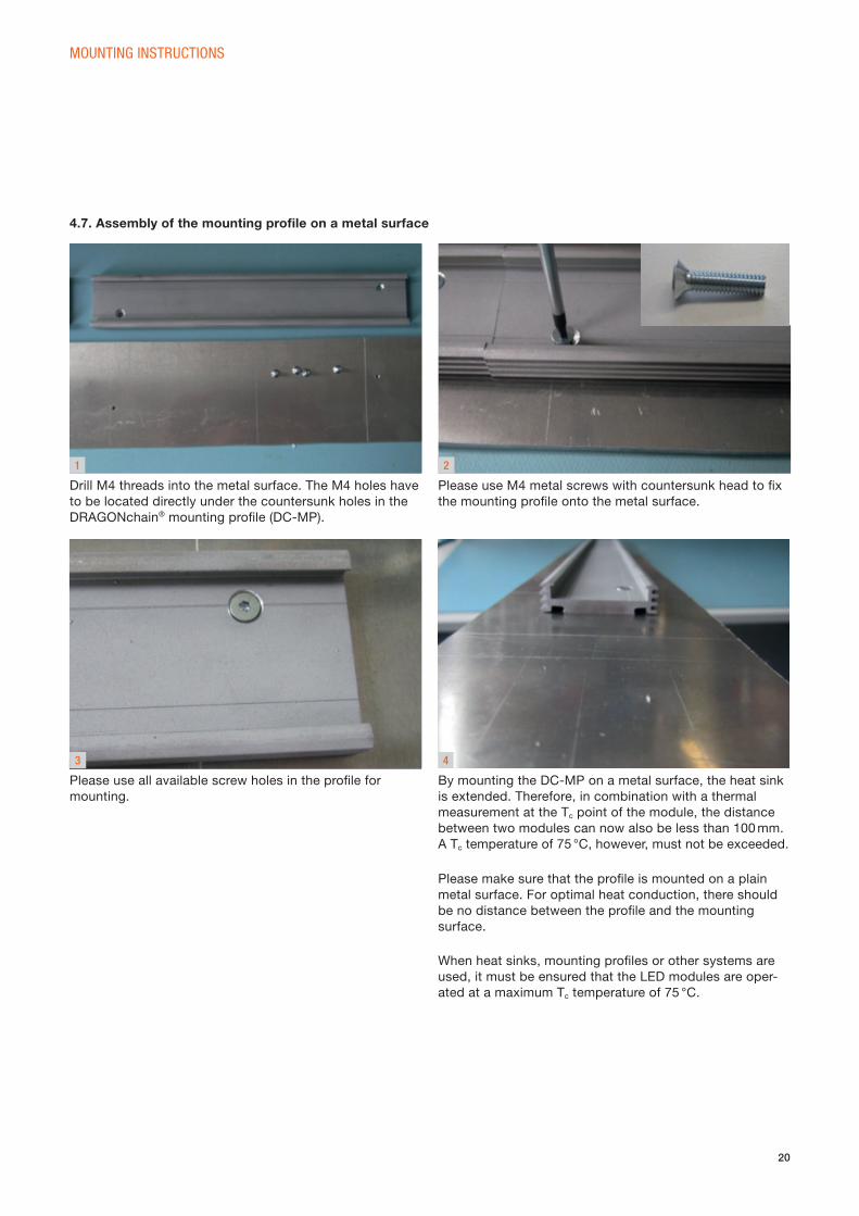
Drill M4 threads into the metal surface. The M4 holes have
to be located directly under the countersunk holes in the
DRAGONchain® mounting profi le (DC-MP).
Please use M4 metal screws with countersunk head to fi x
the mounting profi le onto the metal surface.
Please use all available screw holes in the profi le for
mounting.
4.7. Assembly of the mounting profi le on a metal surface
4
By mounting the DC-MP on a metal surface, the heat sink
is extended. Therefore, in combination with a thermal
measurement at the Tc point of the module, the distance
between two modules can now also be less than 100 mm.
A Tc temperature of 75 °C, however, must not be exceeded.
Please make sure that the profi le is mounted on a plain
metal surface. For optimal heat conduction, there should
be no distance between the profi le and the mounting
surface.
When heat sinks, mounting profi les or other systems are
used, it must be ensured that the LED modules are ope r-
ated at a maximum Tc temperature of 75 °C.
21
APPLICATION OVERVIEW
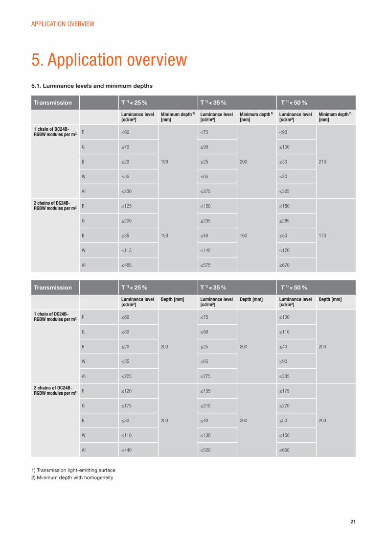
5.1. Luminance levels and minimum depths
5. Application overview
Transmission T 1) < 25 % T 1) < 35 % T 1) < 50 %
Luminance level [cd/m²]
Minimum depth 2) [mm]
Luminance level [cd/m²]
Minimum depth 2) [mm]
Luminance level [cd/m²]
Minimum depth 2) [mm]
1 chain of DC24B- RGBW modules per m² R ≤60
190
≤75
200
≤90
210
G ≤70 ≤90 ≤100
B ≤20 ≤25 ≤30
W ≤55 ≤65 ≤80
All ≤230 ≤275 ≤325
2 chains of DC24B-RGBW modules per m² R ≤125
150
≤150
160
≤180
170
G ≤200 ≤235 ≤285
B ≤35 ≤40 ≤50
W ≤115 ≤140 ≤170
All ≤485 ≤575 ≤670
Transmission T 1) < 25 % T 1) < 35 % T 1) < 50 %
Luminance level [cd/m²]
Depth [mm] Luminance level [cd/m²]
Depth [mm] Luminance level [cd/m²]
Depth [mm]
1 chain of DC24B- RGBW modules per m² R ≤60
200
≤75
200
≤100
200
G ≤80 ≤90 ≤110
B ≤20 ≤25 ≤40
W ≤55 ≤65 ≤90
All ≤225 ≤275 ≤335
2 chains of DC24B-RGBW modules per m² R ≤120
200
≤135
200
≤175
200
G ≤175 ≤210 ≤270
B ≤30 ≤40 ≤50
W ≤110 ≤130 ≤150
All ≤440 ≤520 ≤660
1) Transmission light-emitting surface
2) Minimum depth with homogeneity
22
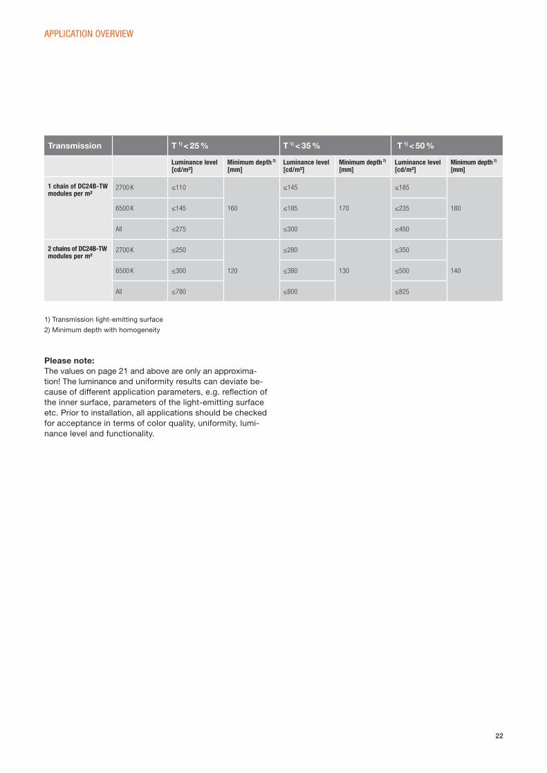
APPLICATION OVERVIEW
Transmission T 1) < 25 % T 1) < 35 % T 1) < 50 %
Luminance level [cd/m²]
Minimum depth 2) [mm]
Luminance level [cd/m²]
Minimum depth 2) [mm]
Luminance level [cd/m²]
Minimum depth 2) [mm]
1 chain of DC24B-TWmodules per m²
2700 K ≤110
160
≤145
170
≤185
1806500 K ≤145 ≤185 ≤235
All ≤275 ≤300 ≤450
2 chains of DC24B-TW modules per m²
2700 K ≤250
120
≤280
130
≤350
1406500 K ≤300 ≤380 ≤500
All ≤780 ≤800 ≤825
Please note:The values on page 21 and above are only an approxima-
tion! The luminance and uniformity results can deviate be-
cause of different application parameters, e.g. refl ection of
the inner surface, parameters of the light-emitting surface
etc. Prior to installation, all applications should be checked
for acceptance in terms of color quality, uniformity, lumi-
nance level and functionality.
1) Transmission light-emitting surface
2) Minimum depth with homogeneity
23
6. Thermal properties
THERMAL PROPERTIES
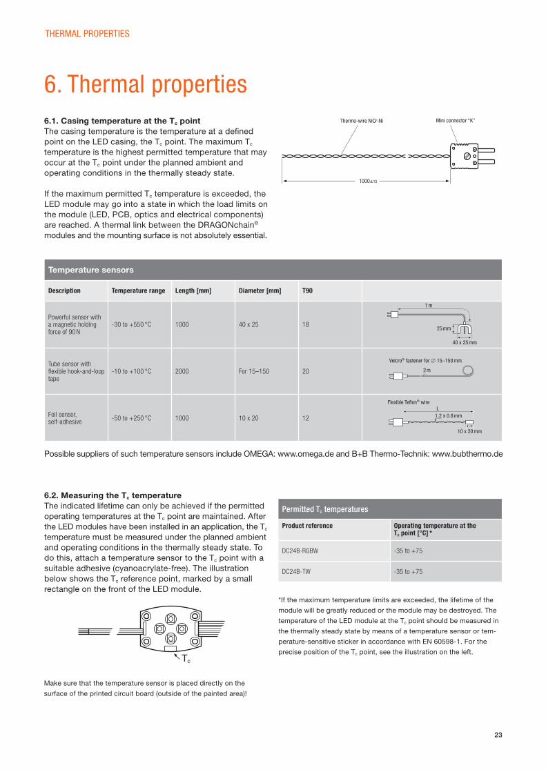
6.1. Casing temperature at the Tc point The casing temperature is the temperature at a defi ned
point on the LED casing, the Tc point. The maximum Tc
temperature is the highest permitted temperature that may
occur at the Tc point under the planned ambient and
operating conditions in the thermally steady state.
If the maximum permitted Tc temperature is exceeded, the
LED module may go into a state in which the load limits on
the module (LED, PCB, optics and electrical components)
are reached. A thermal link between the DRAGONchain®
modules and the mounting surface is not absolutely essential.
6.2. Measuring the Tc temperature
The indicated lifetime can only be achieved if the permitted
operating temperatures at the Tc point are maintained. After
the LED modules have been installed in an application, the Tc
temperature must be measured under the planned ambient
and operating conditions in the thermally steady state. To
do this, attach a temperature sensor to the Tc point with a
suitable adhesive (cyanoacrylate-free). The illustration
below shows the Tc reference point, marked by a small
rectangle on the front of the LED module.
Possible suppliers of such temperature sensors include OMEGA: www.omega.de and B+B Thermo-Technik: www.bubthermo.de
Temperature sensors
Description Temperature range Length [mm] Diameter [mm] T90
Powerful sensor with a magnetic holding force of 90 N
-30 to +550 °C 1000 40 x 25 18
Tube sensor with fl exible hook-and-loop tape
-10 to +100 °C 2000 For 15–150 20
Foil sensor, self- adhesive
-50 to +250 °C 1000 10 x 20 12
Tc
Permitted Tc temperatures
Product reference Operating temperature at the Tc point [°C] *
DC24B-RGBW -35 to +75
DC24B-TW -35 to +75
*If the maximum temperature limits are exceeded, the lifetime of the
module will be greatly reduced or the module may be destroyed. The
temperature of the LED module at the Tc point should be measured in
the thermally steady state by means of a temperature sensor or tem-
perature-sensitive sticker in accordance with EN 60598-1. For the
precise position of the Tc point, see the illustration on the left.
Thermo-wire NiCr-Ni Mini connector “K”
1000±15
1 m
25 mm
40 x 25 mm
Velcro® fastener for ∅ 15–150 mm
2 m
Flexible Tefl on® wire
1.2 x 0.8 mm
10 x 20 mm
L
Make sure that the temperature sensor is placed directly on the
surface of the printed circuit board (outside of the painted area)!
24
7. Norms and standards
NORMS AND STANDARDS
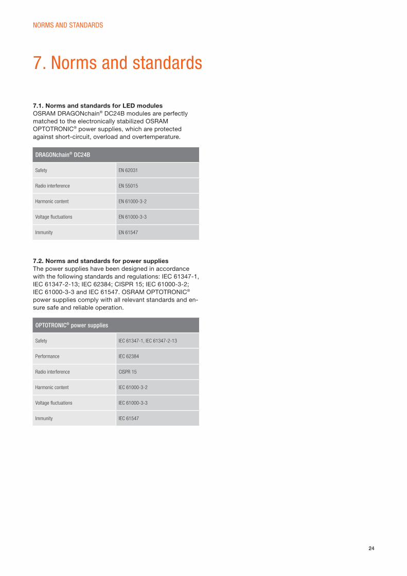
7.1. Norms and standards for LED modules OSRAM DRAGONchain® DC24B modules are perfectly
matched to the electronically stabilized OSRAM
OPTOTRONIC® power supplies, which are protected
against short-circuit, overload and overtemperature.
7.2. Norms and standards for power supplies The power supplies have been designed in accordance
with the following standards and regulations: IEC 61347-1,
IEC 61347-2-13; IEC 62384; CISPR 15; IEC 61000-3-2;
IEC 61000-3-3 and IEC 61547. OSRAM OPTOTRONIC®
power supplies comply with all relevant standards and en-
sure safe and reliable operation.
DRAGONchain® DC24B
Safety EN 62031
Radio interference EN 55015
Harmonic content EN 61000-3-2
Voltage fl uctuations EN 61000-3-3
Immunity EN 61547
OPTOTRONIC® power supplies
Safety IEC 61347-1, IEC 61347-2-13
Performance IEC 62384
Radio interference CISPR 15
Harmonic content IEC 61000-3-2
Voltage fl uctuations IEC 61000-3-3
Immunity IEC 61547
25
8. Notes
NOTES
8.1. General notes • The LED chains must not be used where they may be
directly exposed to the weather without adequate pro-
tection. In outdoor applications, the LED chains must
therefore be protected by suitable housings or covers.
The equipment must not be used in or under water.
• Safe operation is guaranteed only if the LED chains are
connected in parallel. Connecting the LED chains in
series is not recommended. Unbalanced voltage drops
may lead to serious overloads and destruction of individual
modules.
• Make sure to take suitable ESD (electrostatic discharge)
precautions when installing the modules.
• If drivers other than OSRAM OPTOTRONIC® power
supplies are used, the output voltage must be 24 V to
ensure safe operation of the modules.
8.2. Guarantee information
System+ Guarantee from OSRAM. Systematic quality from a single source.LED modules from OSRAM achieve their optimum functio-
nality when operating as a system in conjunction with
OSRAM power supplies, as both components are always
perfectly matched to one another. In addition, OSRAM
offers a guarantee of fi ve years on LMS products used
with OSRAM light management systems or components.
That’s why we offer a comprehensive guarantee for power
supplies, LED modules and LMS components from OSRAM *.
All details on the relevant products and systems, registration
and the general guarantee requirements can be found at:
www.osram.com/system-guarantee
*After registering the system and under certain conditions of use.
8.3. Safety information • The LED module itself and all its components must not
be mechanically stressed.
• Assembly must not damage or destroy conducting paths
on the circuit board.
• The PCBs must be connected ideally to a thermally
conducting surface. Otherwise the lifetime of the
modules shortens.
• The maximum temperature ranges are to be maintained.
• Parallel connection is highly recommended as a safe
electrical operation mode.
• Serial connection is not recommended. Unbalanced voltage
drop can cause hazardous overload and damage the
LED module.
• Observe correct polarity! Depending on the product,
incorrect polarity will lead to emission of red or no light.
The module can be destroyed! Correct the polarity
immediately!
• Installation of LED modules (with power supplies) has to
be carried out with regard to all applicable electrical and
safety standards. Only qualifi ed personnel should be
allowed to perform installations.
• The chain must not be divided.
• Dimming/color control is only possible with PWM.
• Ideally, the DRAGONchain® RGBW/TW is operated by
OSRAM OPTOTRONIC® power supplies and control
gears. Control gears are available with 1…10-V, DALI or
DMX interfaces.
• During dimming operation, the module may produce
interfering noise. In case dimming operation is requested
or required, it is therefore recommended to check the
dimming operation for interfering noise prior to fi nal
installation.
• The power supply has to be short-circuit-proof.
• Please do not look into the LED light source directly and/
or for a longer time.
For the safe application of OSRAM LED modules, it is absolutely necessary to operate them with an electron-ically stabilized power supply which protects them against short circuits, overload and overheating.
OSRAM OPTOTRONIC® electronic control gears guarantee safe operation and comply with all relevant standards.
5 Year
OSRAMGuarantee*
26
9. Further information
FURTHER INFORMATION
Product data sheets, technical guides, operating instruc-
tions, EULUMDATs and more information concerning the
DRAGONchain® LED modules and OPTOTRONIC® devices
are available at the OSRAM website www.osram.com
The catalog with the complete LED portfolio can be found
here: www.osram.com/led
DisclaimerAll information contained in this document has been col-
lected, analyzed and verifi ed with great care by OSRAM.
However, OSRAM is not responsible for the correctness
and completeness of the information contained in this
document and OSRAM cannot be made liable for any
damage that occurs in connection with the use of and/or
reliance on the content of this document. The information
contained in this document refl ects the current state of
knowledge on the date of issue.
www.osram.dewww.osram.dewww.osram.com
OSRAM GmbH
Head Office
Marcel-Breuer-Strasse 6
80807 Munich
Germany
Phone +49 89 6213-0
Fax +49 89 6213-2020
www.osram.com 01/1
5 S
ubje
ct to
cha
nge
with
out n
otic
e. E
rror
s an
d om
issi
ons
exce
pted
.