Statics Primer Notation - Texas A&M...
21
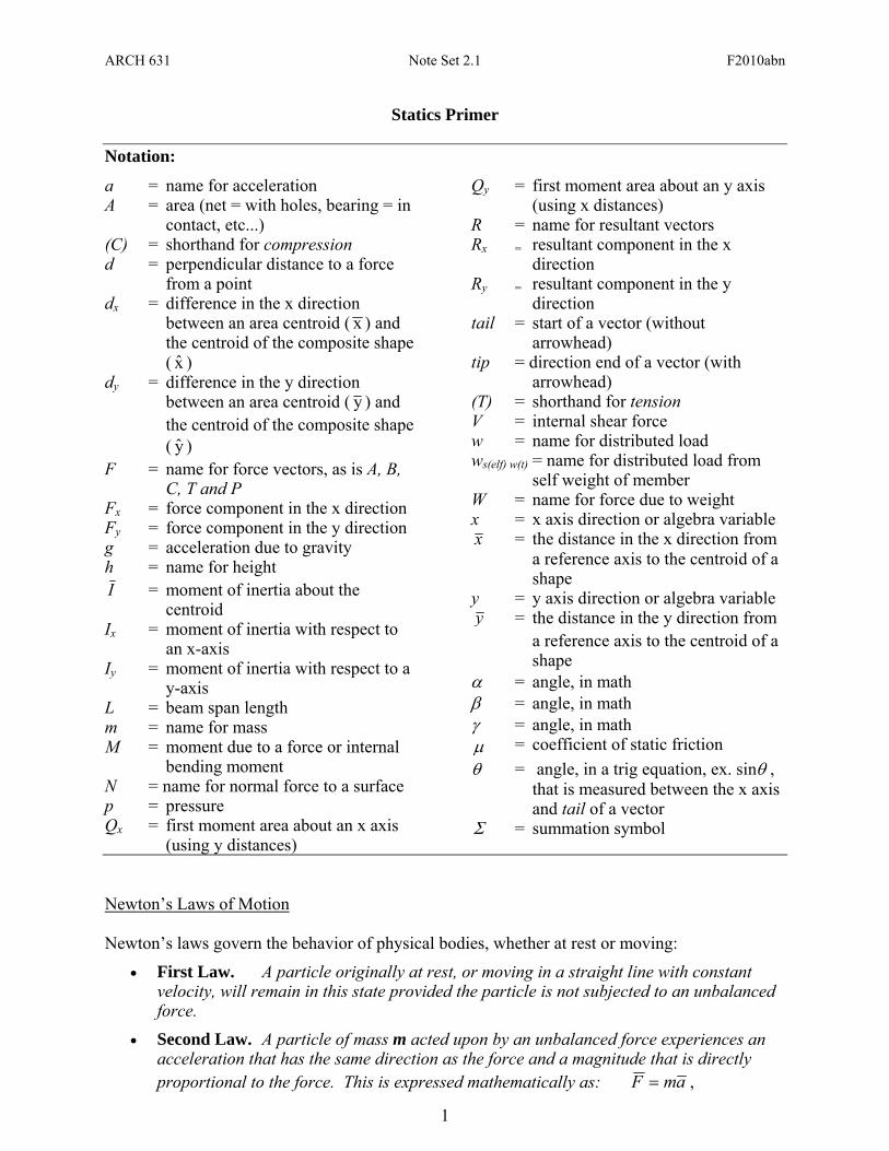
ARCH 631 Note Set 2.1 F2010abn 1 Statics Primer Notation: a = name for acceleration A = area (net = with holes, bearing = in contact, etc...) (C) = shorthand for compression d = perpendicular distance to a force from a point d x = difference in the x direction between an area centroid ( x ) and the centroid of the composite shape ( x ˆ ) d y = difference in the y direction between an area centroid ( y ) and the centroid of the composite shape ( y ˆ ) F = name for force vectors, as is A, B, C, T and P F x = force component in the x direction F y = force component in the y direction g = acceleration due to gravity h = name for height I = moment of inertia about the centroid I x = moment of inertia with respect to an x-axis I y = moment of inertia with respect to a y-axis L = beam span length m = name for mass M = moment due to a force or internal bending moment N = name for normal force to a surface p = pressure Q x = first moment area about an x axis (using y distances) Q y = first moment area about an y axis (using x distances) R = name for resultant vectors R x = resultant component in the x direction R y = resultant component in the y direction tail = start of a vector (without arrowhead) tip = direction end of a vector (with arrowhead) (T) = shorthand for tension V = internal shear force w = name for distributed load w s(elf) w(t) = name for distributed load from self weight of member W = name for force due to weight x = x axis direction or algebra variable x = the distance in the x direction from a reference axis to the centroid of a shape y = y axis direction or algebra variable y = the distance in the y direction from a reference axis to the centroid of a shape α = angle, in math β = angle, in math γ = angle, in math μ = coefficient of static friction θ = angle, in a trig equation, ex. sinθ , that is measured between the x axis and tail of a vector Σ = summation symbol Newton’s Laws of Motion Newton’s laws govern the behavior of physical bodies, whether at rest or moving: • First Law. A particle originally at rest, or moving in a straight line with constant velocity, will remain in this state provided the particle is not subjected to an unbalanced force. • Second Law. A particle of mass m acted upon by an unbalanced force experiences an acceleration that has the same direction as the force and a magnitude that is directly proportional to the force. This is expressed mathematically as: a m F = ,
-
Upload
phungkhanh -
Category
Documents
-
view
227 -
download
2
Transcript of Statics Primer Notation - Texas A&M...
ARCH 631 Note Set 2.1 F2010abn
1
Statics Primer
Notation:
a = name for acceleration A = area (net = with holes, bearing = in
contact, etc...) (C) = shorthand for compression d = perpendicular distance to a force
from a point dx = difference in the x direction
between an area centroid ( x ) and the centroid of the composite shape ( x )
dy = difference in the y direction between an area centroid ( y ) and the centroid of the composite shape ( y )
F = name for force vectors, as is A, B, C, T and P
Fx = force component in the x direction Fy = force component in the y direction g = acceleration due to gravity h = name for height I = moment of inertia about the
centroid Ix = moment of inertia with respect to
an x-axis Iy = moment of inertia with respect to a
y-axis L = beam span length m = name for mass M = moment due to a force or internal
bending moment N = name for normal force to a surface p = pressure Qx = first moment area about an x axis
(using y distances)
Qy = first moment area about an y axis (using x distances)
R = name for resultant vectors Rx = resultant component in the x
direction Ry = resultant component in the y
direction tail = start of a vector (without
arrowhead) tip = direction end of a vector (with
arrowhead) (T) = shorthand for tension V = internal shear force w = name for distributed load ws(elf) w(t) = name for distributed load from
self weight of member W = name for force due to weight x = x axis direction or algebra variable x = the distance in the x direction from
a reference axis to the centroid of a shape
y = y axis direction or algebra variable y = the distance in the y direction from
a reference axis to the centroid of a shape
α = angle, in math β = angle, in math γ = angle, in math μ = coefficient of static friction θ = angle, in a trig equation, ex. sinθ ,
that is measured between the x axis and tail of a vector
Σ = summation symbol
Newton’s Laws of Motion Newton’s laws govern the behavior of physical bodies, whether at rest or moving:
• First Law. A particle originally at rest, or moving in a straight line with constant velocity, will remain in this state provided the particle is not subjected to an unbalanced force.
• Second Law. A particle of mass m acted upon by an unbalanced force experiences an acceleration that has the same direction as the force and a magnitude that is directly proportional to the force. This is expressed mathematically as: amF = ,
ARCH 631 Note Set 2.1 F2010abn
2
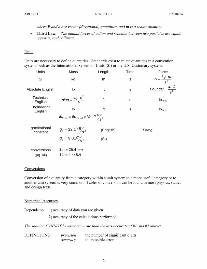
where F and a are vector (directional) quantities, and m is a scalar quantity. • Third Law. The mutual forces of action and reaction between two particles are equal,
opposite, and collinear. Units Units are necessary to define quantities. Standards exist to relate quantities in a convention system, such as the International System of Units (SI) or the U.S. Customary system.
Units Mass Length Time Force
SI kg m s 2smkgN ⋅
=
Absolute English lb ft s 2sftlbPoundal ⋅
=
Technical English ft
slbslug f2⋅
= ft s lbforce
Engineering English lb ft s lbforce
21732s
ft.lblb )mass(force ×=
gravitational
constant 217.32 sftgc = (English) F=mg
281.9 smgc = (SI)
conversions mm.in 4251 =
(pg. vii) N.lb 44841 = Conversions Conversion of a quantity from a category within a unit system to a more useful category or to another unit system is very common. Tables of conversion can be found in most physics, statics and design texts. Numerical Accuracy Depends on 1) accuracy of data you are given
2) accuracy of the calculations performed The solution CANNOT be more accurate than the less accurate of #1 and #2 above! DEFINITIONS: precision the number of significant digits accuracy the possible error
ARCH 631 Note Set 2.1 F2010abn
3
Relative error measures the degree of accuracy: For engineering problems, accuracy rarely is less than 0.2%. Math for Structures
1. Parallel lines never intersect.
2. Two lines are perpendicular (or normal) when they intersect at a right angle = 90°. 3. Intersecting (or concurrent) lines cross or meet at a point. 4. If two lines cross, the opposite angles are identical: 5. If a line crosses two parallel lines, the intersection angles with the same orientation are
identical: 6. If the sides of two angles are parallel and intersect in the same fashion, the angles are
identical. 7. If the sides of two angles are parallel, but intersect in the opposite fashion, the angles are
supplementary: α+β = 180°. 8. If the sides of two angles are perpendicular and intersect in the same fashion, the angles
are identical. 9. If the sides of two angles are perpendicular, but intersect in the opposite fashion, the
angles are supplementary: α+β = 180°. 10. If the side of two angles bisects a right angle, the angles are complimentary:
α+ γ = 90°.
11. If a right angle bisects a straight line, the remaining angles are complimentary: α+ γ = 90°.
12. The sum of the interior angles of a triangle = 180°.
13. For a right triangle, that has one angle of 90°, the sum of the other angles = 90°. 14. For a right triangle, the sum of the squares of the sides equals the square of the
hypotenuse:
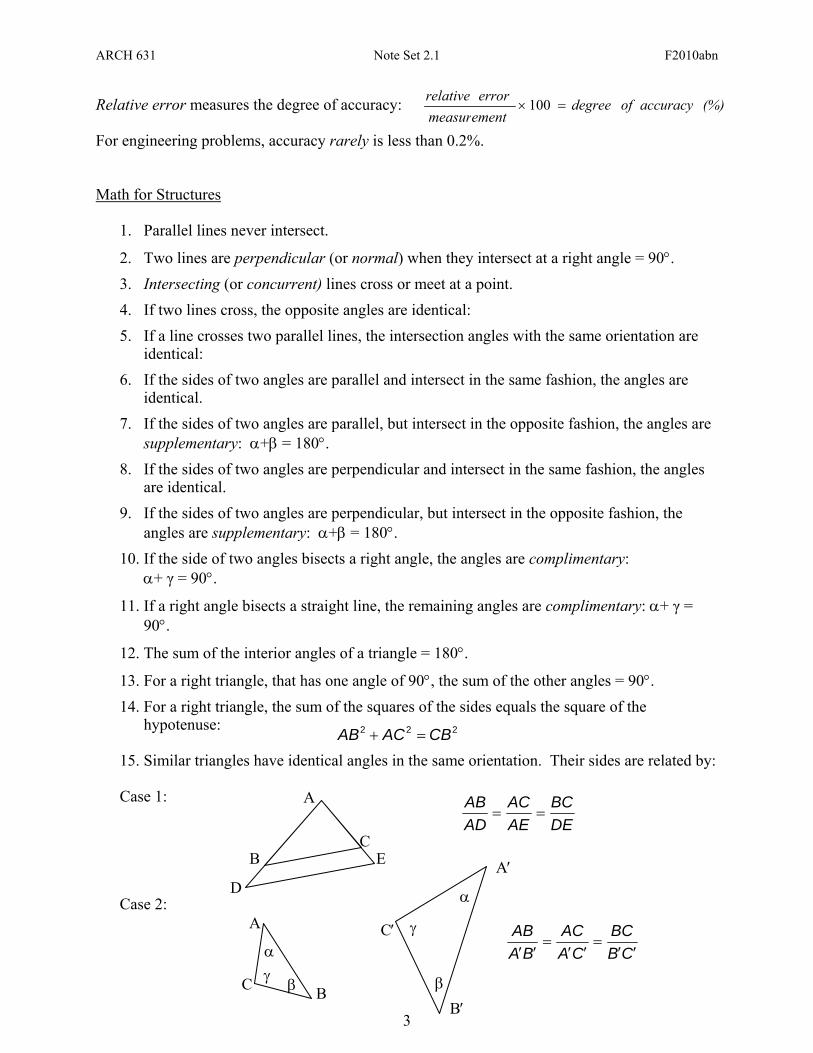
15. Similar triangles have identical angles in the same orientation. Their sides are related by:
Case 1: Case 2:
(%)accuracyofdegreeerrorrelative=× 100
measurement
A
B C β
α γ
D
B C
E
A
222 CBACAB =+
DEBC
AEAC
ADAB
==
CBBC
CAAC
BAAB
′′=
′′=
′′
A′
C′
B′ β
α
γ
ARCH 631 Note Set 2.1 F2010abn
4
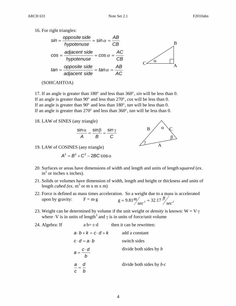
16. For right triangles: (SOHCAHTOA)
17. If an angle is greater than 180° and less than 360°, sin will be less than 0. If an angle is greater than 90° and less than 270°, cos will be less than 0. If an angle is greater than 90° and less than 180°, tan will be less than 0. If an angle is greater than 270° and less than 360°, tan will be less than 0. 18. LAW of SINES (any triangle)
19. LAW of COSINES (any triangle)
20. Surfaces or areas have dimensions of width and length and units of length squared (ex. in2 or inches x inches).
21. Solids or volumes have dimension of width, length and height or thickness and units of length cubed (ex. m3 or m x m x m)
22. Force is defined as mass times acceleration. So a weight due to a mass is accelerated upon by gravity: F = m⋅g
23. Weight can be determined by volume if the unit weight or density is known: W = V⋅γ
where ⋅V is in units of length3 and γ is in units of force/unit volume
24. Algebra: If a⋅b= c⋅d then it can be rewritten:
kdckba +⋅=+⋅ add a constant
badc ⋅=⋅ switch sides
bdca ⋅
= divide both sides by b
bd
ca=
divide both sides by b⋅c
α C
A
B
β γ
CBABsin
hypotenusesideoppositesin === α
A
B
C α CBACcos
hypotenusesideadjacentcos === α
CBAγ
=β
=α sinsinsin
α−+= cos2222 BCCBA
ACABtan
sideadjacentsideoppositetan === α
22 secft
secm 17.329.81g ==
ARCH 631 Note Set 2.1 F2010abn
5
X
Y
O -origin
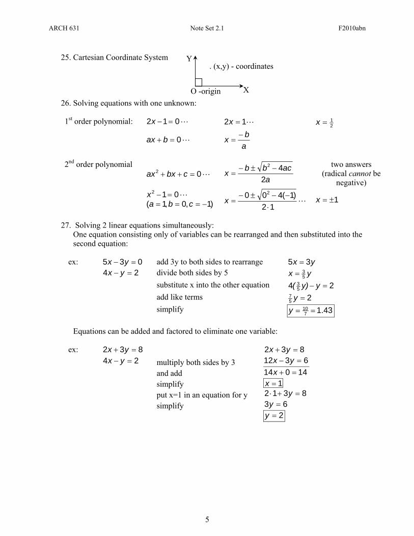
. (x,y) - coordinates 25. Cartesian Coordinate System
26. Solving equations with one unknown:
1st order polynomial: L012 =−x L12 =x 21=x
L0=+ bax
abx −
=
2nd order polynomial
L02 =++ cbxax a
acbbx2
42 −±−=
two answers (radical cannot be
negative) L012 =−x
)1,0,1( −=== cba L12
)1(400 2
⋅−−±−
=x 1±=x
27. Solving 2 linear equations simultaneously:
One equation consisting only of variables can be rearranged and then substituted into the second equation:
ex: 035 =− yx add 3y to both sides to rearrange yx 35 = 24 =− yx divide both sides by 5 yx 5
3= substitute x into the other equation 24 5
3 =− yy)( add like terms 25
7 =y simplify 1.437
10 ==y Equations can be added and factored to eliminate one variable:
ex: 832 =+ yx 832 =+ yx 24 =− yx multiply both sides by 3 6312 =− yx
and add 14014 =+x simplify 1=x put x=1 in an equation for y 8312 =+⋅ y simplify 63 =y 2=y
ARCH 631 Note Set 2.1 F2010abn
6
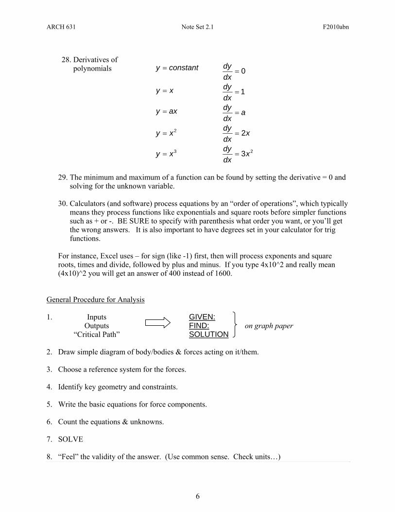
28. Derivatives of
polynomials
constanty = 0=dxdy
xy = 1=dxdy
axy = adxdy
=
2xy = xdxdy 2=
3xy = 23xdxdy
=
29. The minimum and maximum of a function can be found by setting the derivative = 0 and
solving for the unknown variable.
30. Calculators (and software) process equations by an “order of operations”, which typically means they process functions like exponentials and square roots before simpler functions such as + or -. BE SURE to specify with parenthesis what order you want, or you’ll get the wrong answers. It is also important to have degrees set in your calculator for trig functions.
For instance, Excel uses – for sign (like -1) first, then will process exponents and square roots, times and divide, followed by plus and minus. If you type 4x10^2 and really mean (4x10)^2 you will get an answer of 400 instead of 1600.
General Procedure for Analysis 1. Inputs
GIVEN:
on graph paper Outputs FIND: “Critical Path” SOLUTION 2. Draw simple diagram of body/bodies & forces acting on it/them. 3. Choose a reference system for the forces. 4. Identify key geometry and constraints. 5. Write the basic equations for force components. 6. Count the equations & unknowns. 7. SOLVE 8. “Feel” the validity of the answer. (Use common sense. Check units…)
ARCH 631 Note Set 2.1 F2010abn
7
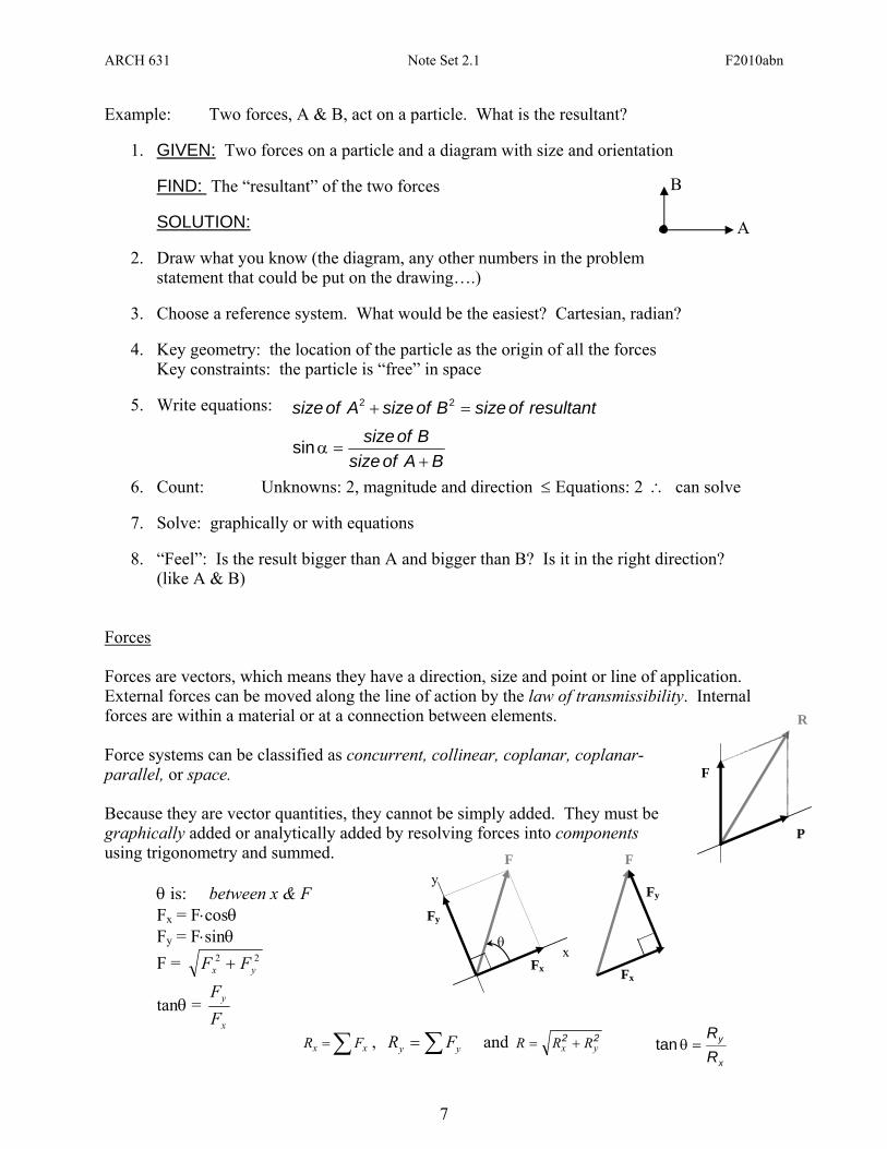
Example: Two forces, A & B, act on a particle. What is the resultant?
1. GIVEN: Two forces on a particle and a diagram with size and orientation
FIND: The “resultant” of the two forces
SOLUTION:
2. Draw what you know (the diagram, any other numbers in the problem statement that could be put on the drawing….)
3. Choose a reference system. What would be the easiest? Cartesian, radian?
4. Key geometry: the location of the particle as the origin of all the forces
Key constraints: the particle is “free” in space
5. Write equations:
6. Count: Unknowns: 2, magnitude and direction ≤ Equations: 2 ∴ can solve
7. Solve: graphically or with equations
8. “Feel”: Is the result bigger than A and bigger than B? Is it in the right direction? (like A & B)
Forces Forces are vectors, which means they have a direction, size and point or line of application. External forces can be moved along the line of action by the law of transmissibility. Internal forces are within a material or at a connection between elements. Force systems can be classified as concurrent, collinear, coplanar, coplanar-parallel, or space. Because they are vector quantities, they cannot be simply added. They must be graphically added or analytically added by resolving forces into components using trigonometry and summed. θ is: between x & F Fx = F⋅cosθ Fy = F⋅sinθ F = 22
yx FF +
tanθ = x
y
FF
A
B
BAofsizeBofsize+
=αsin
resultantofsizeBofsizeAofsize =+ 22
Fy
Fx
θ
F
x
y Fy
Fx
F
F
P
R
∑= xx FR , ∑= yy FR and 22yx RRR +=
x
y
RR
=θtan
ARCH 631 Note Set 2.1 F2010abn
8
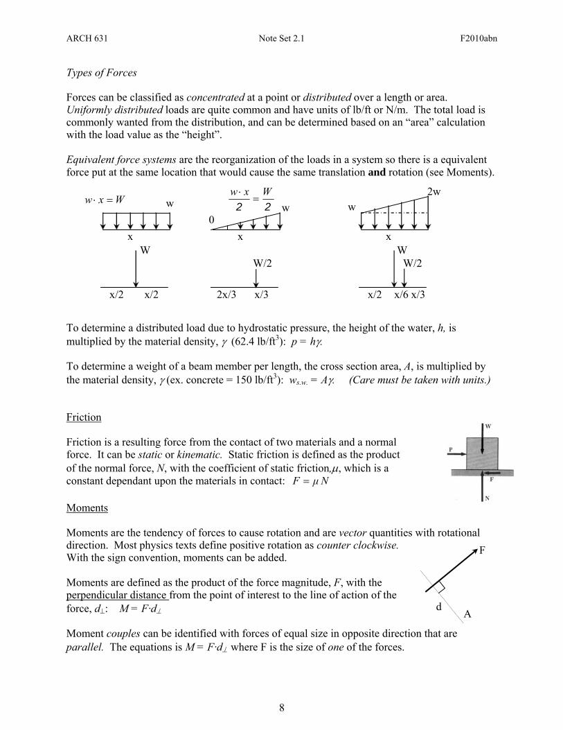
Types of Forces Forces can be classified as concentrated at a point or distributed over a length or area. Uniformly distributed loads are quite common and have units of lb/ft or N/m. The total load is commonly wanted from the distribution, and can be determined based on an “area” calculation with the load value as the “height”. Equivalent force systems are the reorganization of the loads in a system so there is a equivalent force put at the same location that would cause the same translation and rotation (see Moments).
To determine a distributed load due to hydrostatic pressure, the height of the water, h, is multiplied by the material density, γ (62.4 lb/ft3): p = hγ. To determine a weight of a beam member per length, the cross section area, A, is multiplied by the material density, γ (ex. concrete = 150 lb/ft3): ws.w. = Aγ. (Care must be taken with units.) Friction Friction is a resulting force from the contact of two materials and a normal force. It can be static or kinematic. Static friction is defined as the product of the normal force, N, with the coefficient of static friction,μ, which is a constant dependant upon the materials in contact: NμF = Moments Moments are the tendency of forces to cause rotation and are vector quantities with rotational direction. Most physics texts define positive rotation as counter clockwise. With the sign convention, moments can be added. Moments are defined as the product of the force magnitude, F, with the perpendicular distance from the point of interest to the line of action of the force, d⊥: M = F·d⊥ Moment couples can be identified with forces of equal size in opposite direction that are parallel. The equations is M = F·d⊥
where F is the size of one of the forces.
x
x/2
W
x/2
x
2x/3
W/2
x/3
x
x/2
W
x/6 x/3
W/2
Wxw =⋅
0 w w 22
Wxw=
⋅w
2w
F
d A
ARCH 631 Note Set 2.1 F2010abn
9
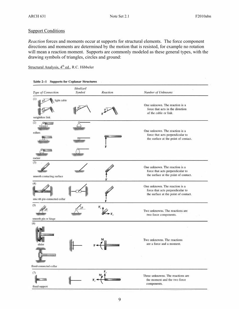
Support Conditions Reaction forces and moments occur at supports for structural elements. The force component directions and moments are determined by the motion that is resisted, for example no rotation will mean a reaction moment. Supports are commonly modeled as these general types, with the drawing symbols of triangles, circles and ground: Structural Analysis, 4th ed., R.C. Hibbeler
ARCH 631 Note Set 2.1 F2010abn
10
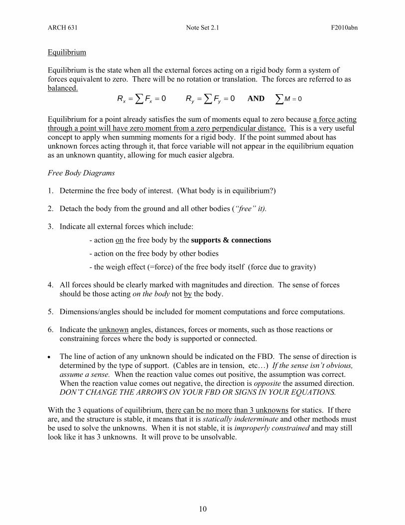
Equilibrium Equilibrium is the state when all the external forces acting on a rigid body form a system of forces equivalent to zero. There will be no rotation or translation. The forces are referred to as balanced. 0== ∑ xx FR 0== ∑ yy FR AND 0=∑M Equilibrium for a point already satisfies the sum of moments equal to zero because a force acting through a point will have zero moment from a zero perpendicular distance. This is a very useful concept to apply when summing moments for a rigid body. If the point summed about has unknown forces acting through it, that force variable will not appear in the equilibrium equation as an unknown quantity, allowing for much easier algebra. Free Body Diagrams 1. Determine the free body of interest. (What body is in equilibrium?) 2. Detach the body from the ground and all other bodies (“free” it). 3. Indicate all external forces which include:
- action on the free body by the supports & connections
- action on the free body by other bodies
- the weigh effect (=force) of the free body itself (force due to gravity) 4. All forces should be clearly marked with magnitudes and direction. The sense of forces
should be those acting on the body not by the body. 5. Dimensions/angles should be included for moment computations and force computations. 6. Indicate the unknown angles, distances, forces or moments, such as those reactions or
constraining forces where the body is supported or connected. • The line of action of any unknown should be indicated on the FBD. The sense of direction is
determined by the type of support. (Cables are in tension, etc…) If the sense isn’t obvious, assume a sense. When the reaction value comes out positive, the assumption was correct. When the reaction value comes out negative, the direction is opposite the assumed direction. DON’T CHANGE THE ARROWS ON YOUR FBD OR SIGNS IN YOUR EQUATIONS.
With the 3 equations of equilibrium, there can be no more than 3 unknowns for statics. If there are, and the structure is stable, it means that it is statically indeterminate and other methods must be used to solve the unknowns. When it is not stable, it is improperly constrained and may still look like it has 3 unknowns. It will prove to be unsolvable.
ARCH 631 Note Set 2.1 F2010abn
11
x
y
.A y
x
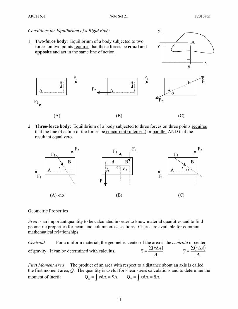
Conditions for Equilibrium of a Rigid Body 1. Two-force body: Equilibrium of a body subjected to two
forces on two points requires that those forces be equal and opposite and act in the same line of action.
A
F2
BF1
d
AF2
BF1
d
A
F2
B F1
α
(A) (B) (C) 2. Three-force body: Equilibrium of a body subjected to three forces on three points requires
that the line of action of the forces be concurrent (intersect) or parallel AND that the resultant equal zero.
F1
F2
A
BC
F3
F2
A
F1
BC
F3
d1
d2
F2
AF1
BC
F3
α
(A) -no (B) (C) Geometric Properties Area is an important quantity to be calculated in order to know material quantities and to find geometric properties for beam and column cross sections. Charts are available for common mathematical relationships. Centroid For a uniform material, the geometric center of the area is the centroid or center
of gravity. It can be determined with calculus. ( )A
Axx Δ∑= ( )
AAyy Δ∑
=
First Moment Area The product of an area with respect to a distance about an axis is called the first moment area, Q. The quantity is useful for shear stress calculations and to determine the moment of inertia. AyydAQx == ∫ AxxdAQy == ∫
ARCH 631 Note Set 2.1 F2010abn
12
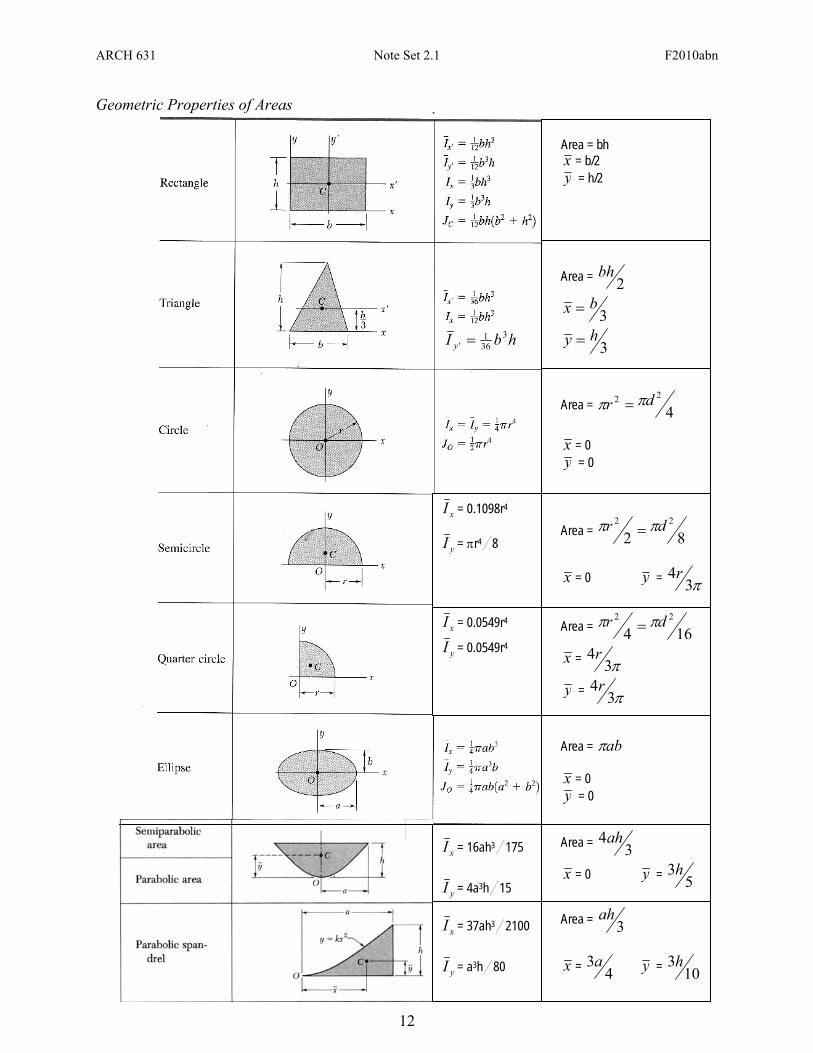
Area = bh x = b/2 y = h/2
Area = 2
bh
3bx =
3hy =
Area = 4
22 dr ππ =
x = 0 y = 0
Area = 82
22 dr ππ =
x = 0 y = π3
4r
Area = 16422 dr ππ =
x = π34r
y = π34r
Area = abπ x = 0 y = 0
Area = 34ah
x = 0 y = 53h
Area = 3ah
x = 4
3a y = 103h
xI = 16ah3/175
yI = 4a3h/15
xI = 37ah3/2100
yI = a3h/80
xI = 0.1098r4
yI = πr4/8
xI = 0.0549r4
yI = 0.0549r4
hbI 'y3
361=
Geometric Properties of Areas
ARCH 631 Note Set 2.1 F2010abn
13
P
Moment of Inertia The moment of inertia is the second area moment of an area, and is found using calculus. For a composite shape, the moment of inertia can be found using the parallel axis theorem: 2
yxx AdII += 2xyy AdII +=
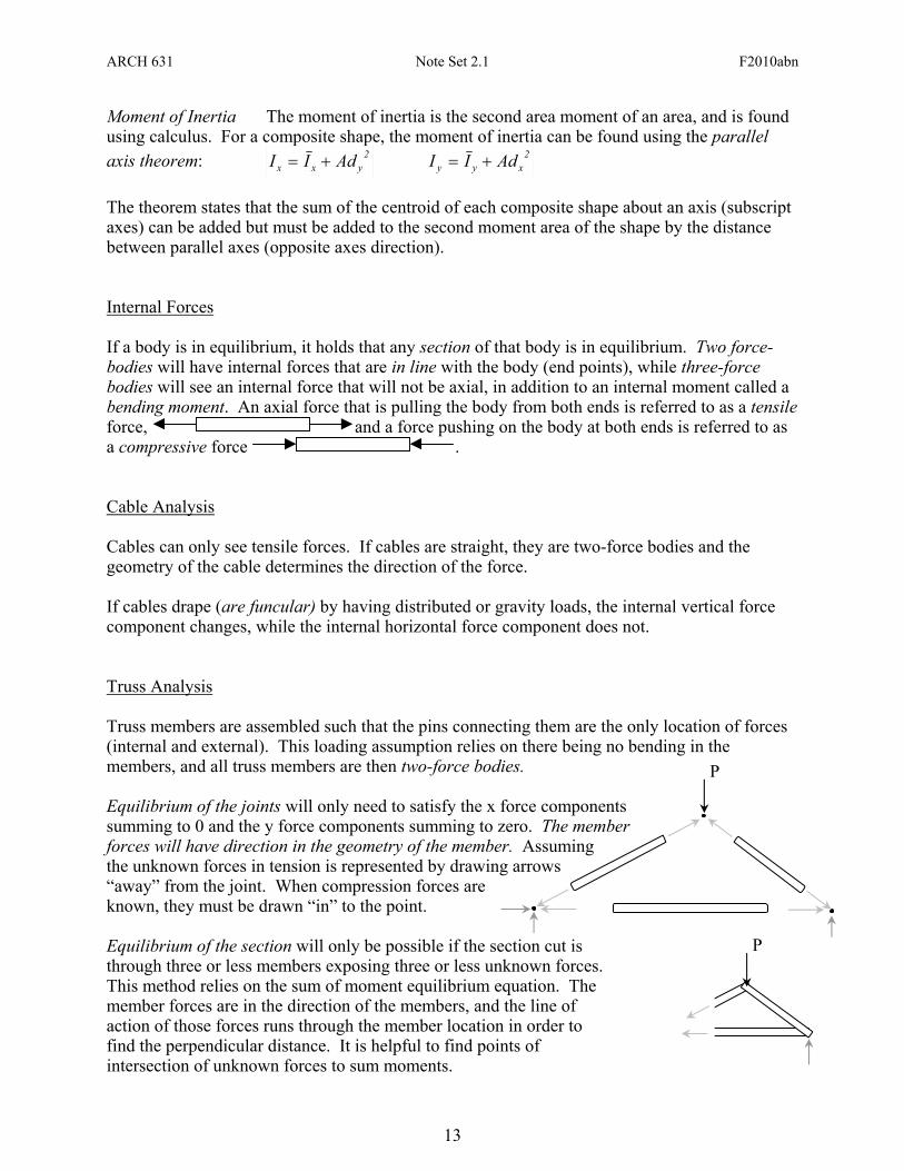
The theorem states that the sum of the centroid of each composite shape about an axis (subscript axes) can be added but must be added to the second moment area of the shape by the distance between parallel axes (opposite axes direction). Internal Forces If a body is in equilibrium, it holds that any section of that body is in equilibrium. Two force-bodies will have internal forces that are in line with the body (end points), while three-force bodies will see an internal force that will not be axial, in addition to an internal moment called a bending moment. An axial force that is pulling the body from both ends is referred to as a tensile force, and a force pushing on the body at both ends is referred to as a compressive force . Cable Analysis Cables can only see tensile forces. If cables are straight, they are two-force bodies and the geometry of the cable determines the direction of the force. If cables drape (are funcular) by having distributed or gravity loads, the internal vertical force component changes, while the internal horizontal force component does not. Truss Analysis Truss members are assembled such that the pins connecting them are the only location of forces (internal and external). This loading assumption relies on there being no bending in the members, and all truss members are then two-force bodies. Equilibrium of the joints will only need to satisfy the x force components summing to 0 and the y force components summing to zero. The member forces will have direction in the geometry of the member. Assuming the unknown forces in tension is represented by drawing arrows “away” from the joint. When compression forces are known, they must be drawn “in” to the point. Equilibrium of the section will only be possible if the section cut is through three or less members exposing three or less unknown forces. This method relies on the sum of moment equilibrium equation. The member forces are in the direction of the members, and the line of action of those forces runs through the member location in order to find the perpendicular distance. It is helpful to find points of intersection of unknown forces to sum moments.
P
ARCH 631 Note Set 2.1 F2010abn
14
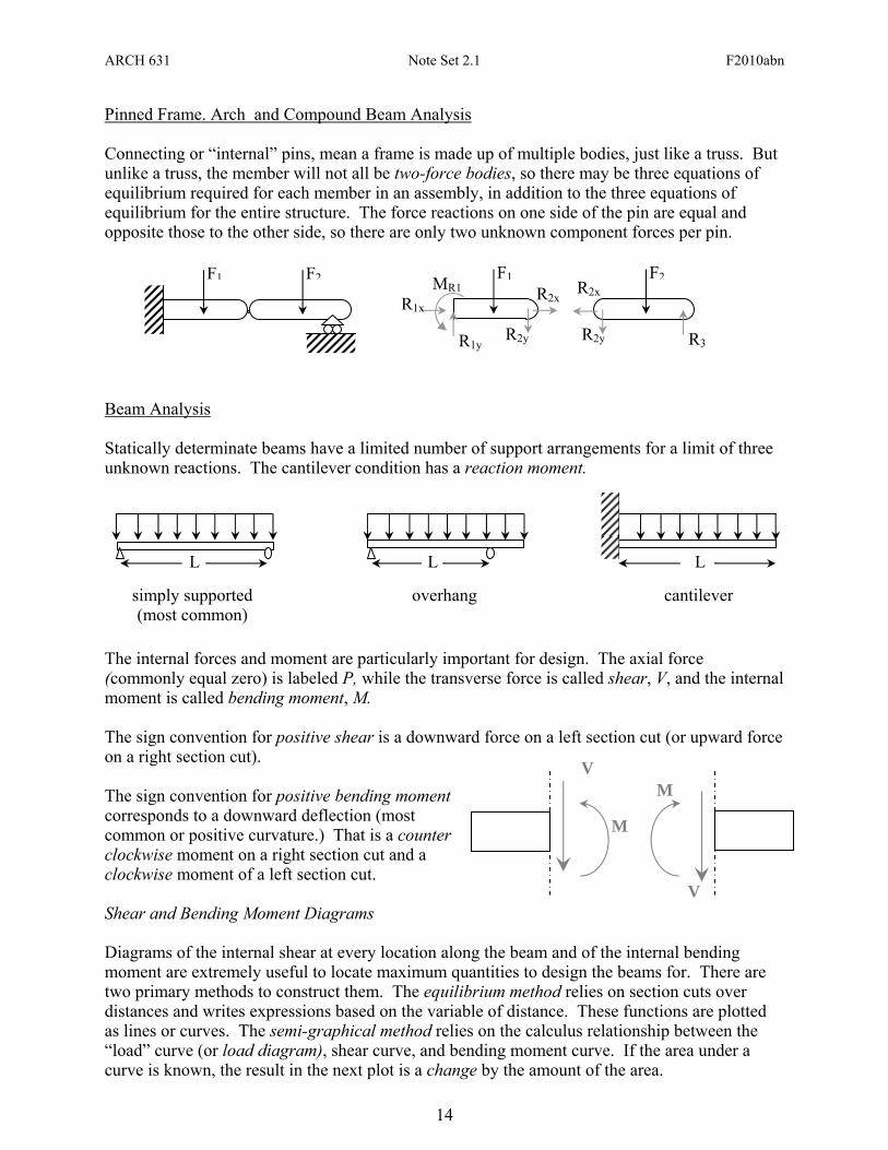
Pinned Frame. Arch and Compound Beam Analysis Connecting or “internal” pins, mean a frame is made up of multiple bodies, just like a truss. But unlike a truss, the member will not all be two-force bodies, so there may be three equations of equilibrium required for each member in an assembly, in addition to the three equations of equilibrium for the entire structure. The force reactions on one side of the pin are equal and opposite those to the other side, so there are only two unknown component forces per pin.
Beam Analysis Statically determinate beams have a limited number of support arrangements for a limit of three unknown reactions. The cantilever condition has a reaction moment.
The internal forces and moment are particularly important for design. The axial force (commonly equal zero) is labeled P, while the transverse force is called shear, V, and the internal moment is called bending moment, M. The sign convention for positive shear is a downward force on a left section cut (or upward force on a right section cut). The sign convention for positive bending moment corresponds to a downward deflection (most common or positive curvature.) That is a counter clockwise moment on a right section cut and a clockwise moment of a left section cut. Shear and Bending Moment Diagrams Diagrams of the internal shear at every location along the beam and of the internal bending moment are extremely useful to locate maximum quantities to design the beams for. There are two primary methods to construct them. The equilibrium method relies on section cuts over distances and writes expressions based on the variable of distance. These functions are plotted as lines or curves. The semi-graphical method relies on the calculus relationship between the “load” curve (or load diagram), shear curve, and bending moment curve. If the area under a curve is known, the result in the next plot is a change by the amount of the area.
F1 F2 F1 F2
R3 R2y R2y R1y
MR1 R1x
R2x R2x
L L L
simply supported (most common)
overhang cantilever
V
M
V
M
ARCH 631 Note Set 2.1 F2010abn
15
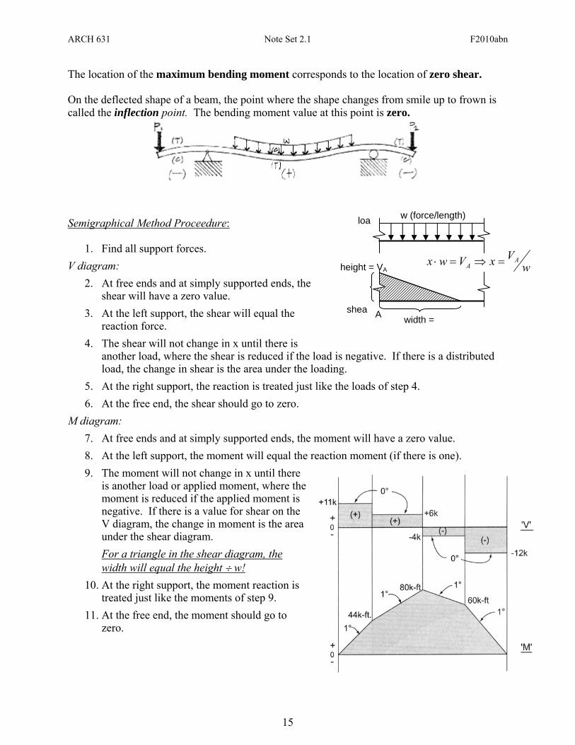
The location of the maximum bending moment corresponds to the location of zero shear. On the deflected shape of a beam, the point where the shape changes from smile up to frown is called the inflection point. The bending moment value at this point is zero.
Semigraphical Method Proceedure:
1. Find all support forces. V diagram:
2. At free ends and at simply supported ends, the shear will have a zero value.
3. At the left support, the shear will equal the reaction force.
4. The shear will not change in x until there is another load, where the shear is reduced if the load is negative. If there is a distributed load, the change in shear is the area under the loading.
5. At the right support, the reaction is treated just like the loads of step 4. 6. At the free end, the shear should go to zero.
M diagram: 7. At free ends and at simply supported ends, the moment will have a zero value. 8. At the left support, the moment will equal the reaction moment (if there is one). 9. The moment will not change in x until there
is another load or applied moment, where the moment is reduced if the applied moment is negative. If there is a value for shear on the V diagram, the change in moment is the area under the shear diagram. For a triangle in the shear diagram, the width will equal the height ÷ w!
10. At the right support, the moment reaction is treated just like the moments of step 9.
11. At the free end, the moment should go to zero.
shea
loa
height = VA
w (force/length)
width = A
wVxVwx A
A =⇒=⋅
ARCH 631 Note Set 2.1 F2010abn
16
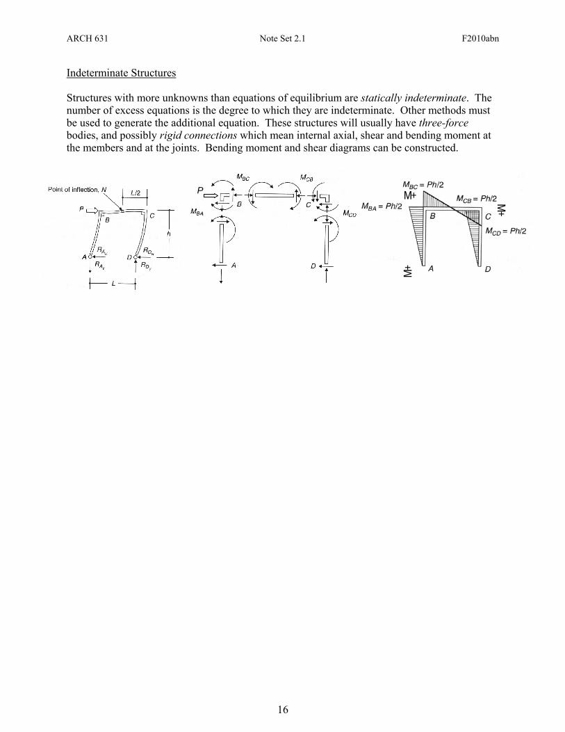
Indeterminate Structures Structures with more unknowns than equations of equilibrium are statically indeterminate. The number of excess equations is the degree to which they are indeterminate. Other methods must be used to generate the additional equation. These structures will usually have three-force bodies, and possibly rigid connections which mean internal axial, shear and bending moment at the members and at the joints. Bending moment and shear diagrams can be constructed.
M+
M+ M+
P
ARCH 631 Note Set 2.1 F2010abn
17
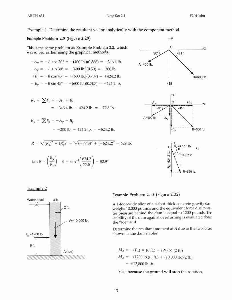
Example 1 Determine the resultant vector analytically with the component method. Example 2
Yes, because the ground will stop the rotation.
ARCH 631 Note Set 2.1 F2010abn
18
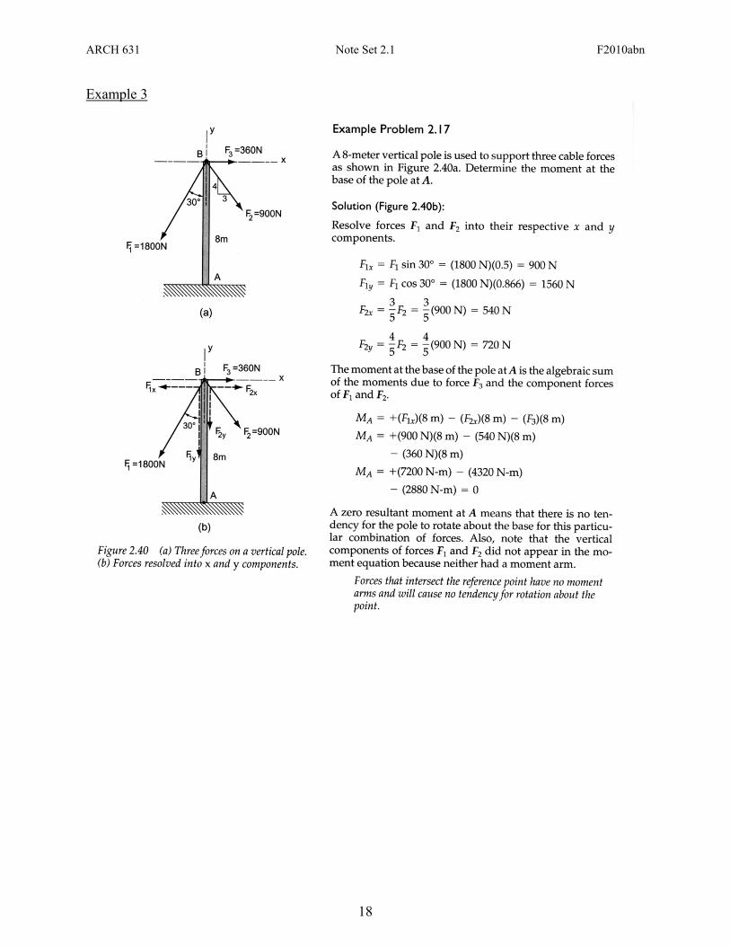
Example 3
ARCH 631 Note Set 2.1 F2010abn
19
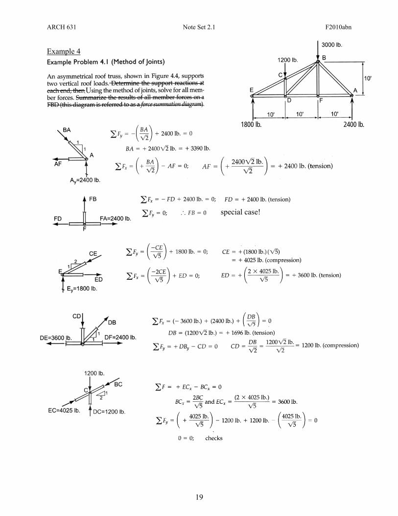
Example 4
U
1800 lb. 2400 lb.
special case!
ARCH 631 Note Set 2.1 F2010abn
20
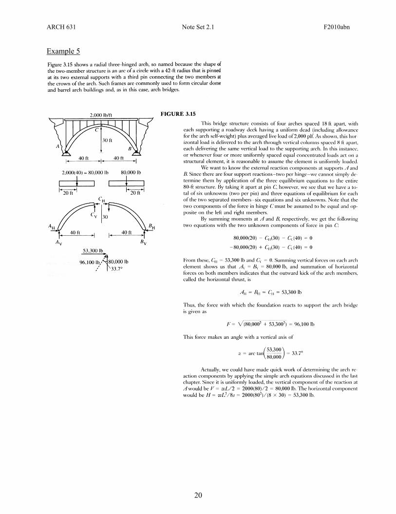
Example 5
ARCH 631 Note Set 2.1 F2010abn
21
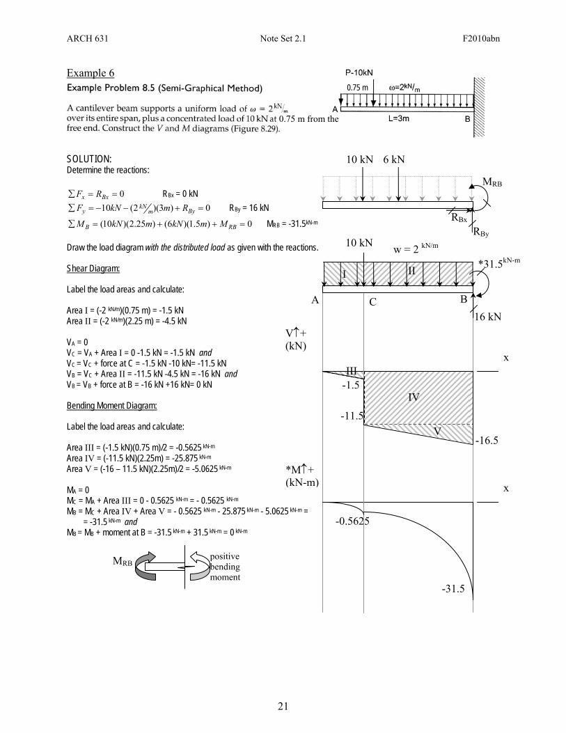
Example 6
SOLUTION: Determine the reactions:
0==∑ Bxx RF RBx = 0 kN 0)3)(2(10 =+−−=∑ Bym
kNy RmkNF RBy = 16 kN
0)5.1)(6()25.2)(10( =++=∑ RBB MmkNmkNM MRB = -31.5kN-m
Draw the load diagram with the distributed load as given with the reactions. Shear Diagram: Label the load areas and calculate: Area I = (-2 kN/m)(0.75 m) = -1.5 kN Area II = (-2 kN/m)(2.25 m) = -4.5 kN VA = 0 VC = VA + Area I = 0 -1.5 kN = -1.5 kN and VC = VC + force at C = -1.5 kN -10 kN= -11.5 kN VB = VC + Area II = -11.5 kN -4.5 kN = -16 kN and VB = VB + force at B = -16 kN +16 kN= 0 kN Bending Moment Diagram: Label the load areas and calculate: Area III = (-1.5 kN)(0.75 m)/2 = -0.5625 kN-m
Area IV = (-11.5 kN)(2.25m) = -25.875 kN-m Area V = (-16 – 11.5 kN)(2.25m)/2 = -5.0625 kN-m MA = 0 MC = MA + Area III = 0 - 0.5625 kN-m = - 0.5625 kN-m MB = MC + Area IV + Area V = - 0.5625 kN-m - 25.875 kN-m - 5.0625 kN-m = = -31.5 kN-m and MB = MB + moment at B = -31.5 kN-m + 31.5 kN-m = 0 kN-m
0.75 m
0.75 m from the
MRB positive bending moment
6 kN 10 kN
RBx
RBy
MRB
x
V↑+ (kN)
x *M↑+ (kN-m)
-1.5
16 kN
*31.5kN-mw = 2 kN/m
A BC
I II
III
IV
V -11.5
-16.5
-0.5625
-31.5
10 kN