Standard specification D1751M Model code Temp. Range …
3
0 100 200 300 400 500 600 0 2 4 6 8 10 12 14 16 Airflow [m 3 /min] 40 50 60 70 80 90 Noise[dB] D1751M...B2 D1751M...B2 D1751M Series φ172 × 150 × 51 mm G-29 Fans & Blowers Axial Centrifugal Silent Axial Centrifugal Option DC fans AC fans www.nidec-servo.com 2016 D1751M12B2AZ-00 D1751M24B2AZ-00 12 24 8.4-13.8 12-27.6 800 400 2900 1900 φ172×150×51 (φ6.8"×6.0"×2.0") Max. airflow:13.8 m 3 /min Max. static pressure :600 Pa Mass :780 g DC Axial Fan D1751M ■Standard airflow and static pressure characteristics (At rated voltage) (6.77dia.) (6.378dia.±0.012) (0.3) (0.3) (5.91) (11.8±1.2) (2±0.02) (8-0.18dia.) 150 7.5 51 7.5 172 φ 300 ±30 4.5±0.3 8- φ 162 ± 0.3 φ 111°±2° Lead wire spec. AWG24 UL3266 ■Standard specification Model code Max. airflow m 3 /min CFM Max. static pressure Noise dB Speed min -1 Current mA Voltage spec. V Pa inH2O Operating Temp. Range ℃ Rating Operating Range -20 ~ +70 Rating Starting Fan model code D1751M12B2AZ-00 D1751M12B2AS-00 D1751M24B2AZ-00 ●Lead wire type 5.8 205 120 0.48 49 2800 ● Figures in the table are average measured values. Please request the product delivery specification when preparing a purchase specification. ● The characteristics are the values at rated voltage (12 V, 24 V, 48 V), and normal temperature and humidity. ■General specification ■Mouting hole dimensions in mm (inches) [Recommendation] Materials Used Motor Common Elec. Spec. Standard Carton Venturi: Aluminum alloy die castings Propelle: ABS and PBT synthetic resins Bearing: Both side shielded ball bearing Brushless DC motor, Protection type: Overcurrent detection and automatic resetting by current limiting See pages G-11, G-12, G-13. 12 to a carton of (450 x 380 x 220)mm, mass 10kg 2-R5 2- φ4.5 (2-0.18dia.) 146 (5.75) 162 (6.378) (3-0.18dia.) 111° R5 146 (5.75) ? 1 6 6 ( 6 . 5 4 d i a . ) ( ? 1 6 0 ) φ (6.54dia.) (φ160) ( 6 . 3 7 8 ) ? 1 6 6 ( 6 . 5 4 d i a . ) ( ? 1 6 0 ) (6.378) φ166 (6.54dia.) ( φ160) 166 (2 point mounting) (3 point mounting) Options (sold separately) ・ Guard: GUARD172 Intake sid e ● NIDEC SERVO can meet many of your requirements for customization, such as special connectors, other sensors not listed above, variable speed specifications, and other modifications. Please contact NIDEC SERVO during your product planning and development stage. ● PWM (pulse width modulation) allowing for variable speed control is available in some models (reference the G-51 spec.) ● The listed products are registered in the following overseas standards files, UL/cUL: E48889, TUV: R50004410 Sensor Spec. G-15 Options G-64 ■External dimensions in mm (inches) 3-φ4.5 Brushless DC Fans & Blowers Rated Vol. 12 V Model Code D1751M12B2AS-00 DC axial fan with sensor Static pressure[Pa]
Transcript of Standard specification D1751M Model code Temp. Range …
0
100
200
300
400
500
600
0 2 4 6 8 10 12 14 16
Airflow [m3/min]
40
50
60
70
80
90
Noi
se[d
B]
D1751M...B2
D1751M...B2
D1751M Series φ172 × 150 × 51 mm
G-29
Fan
s&
Blo
wers
Axial
Centrifugal
Silent
Axia l
Centrifugal
Option
DC
fansA
Cfans
www.nidec-servo.com 2016
D1751M12B2AZ-00D1751M24B2AZ-00
1224
8.4-13.812-27.6
800400
29001900
φ172×150×51(φ6.8"×6.0"×2.0")Max. airflow:13.8 m3/minMax. static pressure:600 PaMass:780 g
DC Axial Fan
D1751M
■Standard airflow and static pressurecharacteristics (At rated voltage)
(6.7
7dia
.)
(6.378dia.±0.012)
(0.3)(0.3)
(5.91)
(11.8±1.2)
(2±0.02)
(8-0.18dia.)
150 7.5
51
7.5
172
φ
300±30
4.5 ±0.38-φ
162 ± 0.3φ
111°± 2 °
Lead wire spec. AWG24 UL3266
■Standard specificationModel code
Max. airflowm3/min CFM
Max. static pressure NoisedB
Speedmin-1
Current mAVoltage spec. VPa inH2O
OperatingTemp. Range ℃Rating Operating Range
-20 ~ +70
Rating Starting
Fan model code
D1751M12B2AZ-00
D1751M12B2AS-00
D1751M24B2AZ-00
●Lead wire type
5.8 205 120 0.48 49 2800
● Figures in the table are average measured values. Please request the product delivery specification when preparing a purchase specification.
● The characteristics are the values at rated voltage (12 V, 24 V, 48 V), and normal temperature and humidity.
■General specification ■Mouting hole dimensions in mm (inches) [Recommendation]
Materials Used
Motor
Common Elec. Spec.
Standard Carton
Venturi: Aluminum alloy die castingsPropelle: ABS and PBT synthetic resinsBearing: Both side shielded ball bearing
Brushless DC motor, Protection type: Overcurrentdetection and automatic resetting by current limiting
See pages G-11, G-12, G-13.
12 to a carton of (450 x 380 x 220)mm, mass 10kg
2-R5
2 -φ 4.5(2-0.18dia.)
146(5.75)
162(
6.37
8)
(3-0.18dia.)
111°
R5
146(5.75)
? 166(6.54dia.)
(? 160)
φ (
6.54dia.)
(φ 160)
(6.378)?16
6(6.
54di
a.)
(
?16
0)
(6.378)φ 16
6(6.
54di
a.)
(
φ 16
0)
166
(2 point mounting) (3 point mounting)
Options(sold separately) ・ Guard: GUARD172
Inta
ke s
ide
● NIDEC SERVO can meet many of your requirements for customization, such as special connectors, other sensors not listed above, variable speedspecifications, and other modifications. Please contact NIDEC SERVO during your product planning and development stage.
● PWM (pulse width modulation) allowing for variable speed control is available in some models (reference the G-51 spec.)● The listed products are registered in the following overseas standards files, UL/cUL: E48889, TUV: R50004410
Sensor Spec. G-15 Options G-64
■External dimensions in mm (inches)
3-φ4.5
Brushless
DC Fans & Blowers
Rated Vol.
12 V
Model Code
D1751M12B2AS-00
DC axial fan with sensor
Stat
ic p
ress
ure[
Pa]

Guards (Options)
G-64 www.nidec-servo.com 2008/2009_A
Axial
Centrifugal
SilentA
xialC
entrifugalO
ptionFans
&B
lowers
DC
fansA
Cfans
Accessories
□50
□59
4-φ4.5±0.3
φ52φ38
5
2.5
φ32
Material: Polycarbonate (black)UL94V-2
F80UL Guard (Mass 14 g)
5±0.5
□71.5(φ17)
φ76.2
4-φ4.5±0.5
Material: Mild steel wire 1.6 dia.Surface treatment:Nickel chromium plating
F60UL Guard (Mass 12 g)
(3.6)
φ 58
φ10 50
4-φ4.6±0.2 4
Material: Mild steel wire 1.6 dia.Surface treatment:Nickel chromium plating
F92UL Guard (Mass 16 g)
5±0.5
□82.5
(φ17)
φ89.4
4-φ4.5±0.5
Material: Mild steel wire 1.6 dia.Surface treatment:Nickel chromium plating
GUARD 172
φ11
.2
φ14
8.6
161
62-φ4.8±0.8
Material: Mild steel wire 2 dia.Surface treatment:Nickel chromium plating
F200UL Guard (Mass 82 g)
φ17
5+2
φ19 +2
φ188.4(Mounting pitch)
4.3
(Inner dimension)
+0.4
-
0.2
1.5 (182
.3)
4.7
φ195.8 +1.5 -1
Material: Mild steel wire 1.6 dia.Surface treatment:Nickel chromium plating
SCN Guard (Mass 55 g)
φ13
8
43.5
φ126
φ29
Material: Mild steel wire 1.6 dia.Surface treatment:Nickel chromium plating
・Guard special for intake side of SCN (metal venturi) fans.
F180UL Guard
152.7
±0.7
(9)64-R3±0.4
φ30
φ45
φ176
(Inner dimension)
Material: Mild steel wire 1.6 dia.Surface treatment:Nickel chromium plating
F120UL Guard (Mass 29 g)
□104.8±0.5
5±0.5
(φ17)
φ115.6
4-φ4.5±0.5
Material: Mild steel wire 1.6 dia.Surface treatment:Nickel chromium plating
F127UL Guard
5.9±0.5□113.3±0.5
4-φ4.6±0.5
Material: Mild steel wire 1.6 dia.Surface treatment:Nickel chromium plating
○○
○○
○
○
SCNVEWEKACUCNMAPATUDCPUDCD0925CKLDCD1225CCNDCD1238BD1338BD1751MD1751SG0638DG0838XG0938BG1238BG1751M
○
○
○
○
○○
○○
○
○*1
○○
○○○
○
○*2
○
○
F60P Guard (Mass 4 g)
Guard F60P F80UL
F92UL
F120UL
F127UL
GUARD172
F180UL
F200UL SCN
snaF
laix
AC
Dsn
aFl a
ixA
CA
*1: Can be installed only on outlet side. *2: Can be installed only on intake side. All guards conform to the UL standard when combined with NIDEC SERVO fans. The installation of a filter, guard and other accessories will constitute a ventilating load,reducing the airflow.Select a suitable guard, taking into consideration the increase in airresistance. (See Figs. 12 and 13 on page G-7.)
List of mating fan seriesF60UL
The DC fans and blowers of NIDEC SERVO have a function to send analarm signal when the fan motor revolutions slow down. Several systemsare used to cut off the system power supply by this alarm signal, with threetypes of sensors available. Select the right type of sensor in accordance withthe purpose of use. The lead wire for the sensor is yellow. The output type isan open collector output for all three types.
■■ Sensor type
1. Lock detection type (Product code: S)
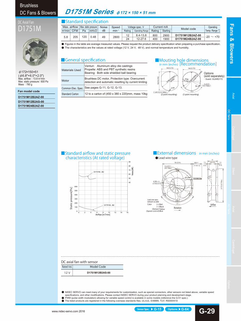
The output signal indicates an [L] state (transistor is ON) while thepropeller is rotating, changing to an [H] state (transistor is OFF) less thanfive seconds after the propeller stops rotating. The propeller automaticallyrestarts operation within five seconds when the lock is unlocked. ([H] → [L]5 s). If the pull-up voltage is live, the [H] state (transistor is OFF) will engagein less than five seconds, even when the power is turned off.
2. Pulse output type (Product code: P)
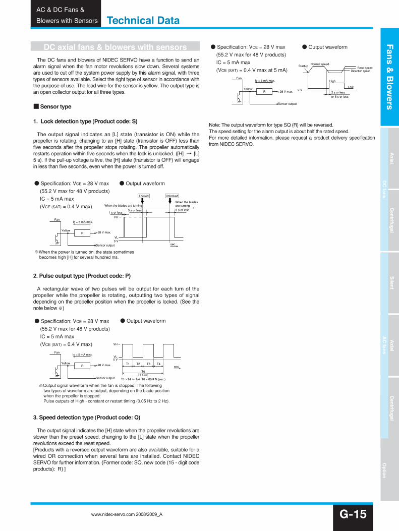
A rectangular wave of two pulses will be output for each turn of thepropeller while the propeller is rotating, outputting two types of signaldepending on the propeller position when the propeller is locked. (See thenote below ※)
3. Speed detection type (Product code: Q)
The output signal indicates the [H] state when the propeller revolutions areslower than the preset speed, changing to the [L] state when the propellerrevolutions exceed the reset speed. [Products with a reversed output waveform are also available, suitable for awired OR connection when several fans are installed. Contact NIDECSERVO for further information. {Former code: SQ, new code (15 - digit codeproducts): R} ]
Note: The output waveform for type SQ (R) will be reversed.The speed setting for the alarm output is about half the rated speed.For more detailed information, please request a product delivery specificationfrom NIDEC SERVO.
DC axial fans & blowers with sensors
G-15
Technical DataAC & DC Fans &
Blowers with Sensors
Fan
Yellow+28 V max.
Sensor output
VL0 V
VH
1 s or less5 s or less
When the blades are turning
UnlockedLocked
When the blades are turning5 s or less
sec.
R
● Output waveform
※When the power is turned on, the state sometimes becomes high [H] for several hundred ms.
● Specification: VCE = 28 V max (55.2 V max for 48 V products) IC = 5 mA max (VCE (SAT) = 0.4 V max)
Ic = 5 mA max.
Fan
Yellow+28 V max.
Sensor output
VH
VL0 V
T1 T2 T3
T0(1 turn)
T1~T4 ≒ 1/4 T0 = 60/4 N (sec.)
sec.T4
R
● Output waveform● Specification: VCE = 28 V max (55.2 V max for 48 V products) IC = 5 mA max (VCE (SAT) = 0.4 V max)
※Output signal waveform when the fan is stopped: The following two types of waveform are output, depending on the blade position when the propeller is stopped: Pulse outputs of High - constant or restart timing (0.05 Hz to 2 Hz).
Ic = 5 mA max.
Fan
Yellow
Ic = 5 mA max.
+28 V max.
Sensor output
0 V2 s or less or 5 s or less
Reset speedNormal speed
Detection speed
Low
High
Startup
R
● Output waveform● Specification: VCE = 28 V max (55.2 V max for 48 V products) IC = 5 mA max (VCE (SAT) = 0.4 V max at 5 mA)
Fans&Blowers
Axial
Centrifugal
Silent
Axial
Centrifugal
Option
DCfans
ACfans
www.nidec-servo.com 2008/2009_A