Spectrum Analyzers FSEx - Electro Rent Corporation
20
◆ Spectrum analysis with ultra-wide dynamic range Noise figure = 18 dB/TOI = 20 dBm typ. (FSEB) ◆ Universal analysis of digital and analog modulated signals (option) such as BPSK, QPSK, π/4-DQPSK, 8PSK, QAM, MSK, GMSK, 2FSK, AM, FM, PM ◆ High-speed synthesizer 5 ms for full span (FSEA, FSEB) ◆ Refresh rate, quasi-analog 25 sweeps/s ◆ Large LC TFT display 24 cm/9.5", active ◆ Future-proof modular design Customized solutions through wide variety of options Spectrum Analyzers FSEx 20 Hz to 40 GHz
Transcript of Spectrum Analyzers FSEx - Electro Rent Corporation
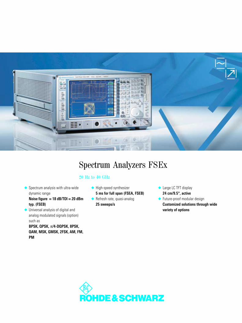
Spectrum analysis with ultra-wide dynamic rangeNoise figure = 18 dB/TOI = 20 dBm typ. (FSEB)
Universal analysis of digital and analog modulated signals (option) such asBPSK, QPSK, π/4-DQPSK, 8PSK, QAM, MSK, GMSK, 2FSK, AM, FM, PM
High-speed synthesizer5 ms for full span (FSEA, FSEB)
Refresh rate, quasi-analog25 sweeps/s
Large LC TFT display24 cm/9.5", active
Future-proof modular designCustomized solutions through wide variety of options
Spectrum Analyzers FSEx20 Hz to 40 GHz
((Bes
chni
ttkan
te))
Au s
kla p
psei
te 1
(vor
ne)
((ei n
gekl
a ppt
er Z
usta
nd))
The spectrum analyzers from Rohde&Schwarz
Characteristics
Combines the following functions: spectrum analysis and analysis of dig-itally modulated signals (option)
Spectrum analysis with maximum dynamic range
Adaptation of all models to your spe-cific requirements by means of a wide range of options
Overview
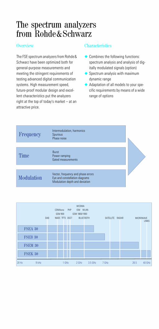
The FSE spectrum analyzers from Rohde& Schwarz have been optimized both for general-purpose measurements and meeting the stringent requirements of testing advanced digital communication systems. High measurement speed, future-proof modular design and excel-lent characteristics put the analyzers right at the top of today's market – at an attractive price.
20 Hz 9 kHz 1 GHz 2 GHz 3.5 GHz 7 GHz 26.5 40 GHz
FSEA 30
FSEB 30
DAB NADC TFTS DECT BLUETOOTH
GSM 900 GSM 1800/1900
CDMAone PHP ISM WLAN
SATELLITE MICROWAVELINKS
WCDMA
FSEM 30
FSEK 30
RADAR
FrequencyIntermodulation, harmonicsSpuriousPhase noise
Time
Modulation
BurstPower rampingGated measurements
Vector, frequency and phase errorsEye and constellation diagramsModulation depth and deviation
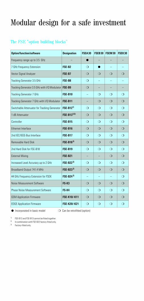
The FSE "option building blocks"
Option/function/software Designation FSEA30 FSEB30 FSEM30 FSEK30
Frequency range up to 3.5 GHz – – – –
7 GHz Frequency Extension FSE-B2 – –
Vector Signal Analyzer FSE-B7
Tracking Generator 3.5 GHz FSE-B8 – – –
Tracking Generator 3.5 GHz with I/Q Modulator FSE-B9 – – –
Tracking Generator 7 GHz FSE-B10 –
Tracking Generator 7 GHz with I/Q Modulator FSE-B11 –
Switchable Attenuator for Tracking Generator FSE-B121)
1) FSE-B12 and FSE-B13 cannot be fitted together.
1 dB Attenuator FSE-B131)2)
2) In combination with FSE-B22 factory-fitted only.
Controller FSE-B15
Ethernet Interface FSE-B16
2nd IEC/IEEE-Bus Interface FSE-B17
Removable Hard Disk FSE-B183)
3) Factory-fitted only.
2nd Hard Disk for FSE-B18 FSE-B19
External Mixing FSE-B21 – –
Increased Level Accuracy up to 2 GHz FSE-B223)
Broadband Output 741.4 MHz FSE-B233)
44 GHz Frequency Extension for FSEK FSE-B243) – – –
Noise Measurement Software FS-K3
Phase Noise Measurement Software FS-K4
GSM Application Firmware FSE-K10/-K11
EDGE Application Firmware FSE-K20/-K21
Incorporated in basic model Can be retrofitted (option)
Modular design for a safe investment
((Bes
chni
ttkan
te))
Au s
kla p
p sei
te 2
( vor
n e)
((aus
gekl
appt
er Z
usta
n d))
2 Spectrum Analyzers FSEx
Getting down to analysis
Specifications in brief
Resolution bandwidths 1 Hz to 10 MHz, adjustable in steps of 1/2/3/5/10
Displayed noise floor –150 dBm (typ.) in 10 Hz bandwidth
3rd-order intercept point +20 dBm typ.
1 dB compression point of RF input +10 dBm
Phase noise at 10 kHz from carrier: –123 dBc (Hz) (typ.) (FSEA 30)
Total level measurement uncertainty up to 1 GHz <1 dB, up to 7 GHz 1.5 dB
AM/FM audio demodulator (with built-in loudspeaker and headphones connector)
Internal RF trigger (trigger threshold approx. –20 dBm)
5 ms full-span sweep time with fully synchronized sweep (FSEA, FSEB), 150 ms with FSEM, 230 ms with FSEK
1 µs zero-span sweep time Pretrigger and trigger delay Gated sweep
Vector analysis for digital communication
The analyzers of the FSE family combine the capabilities of high-end RF or micro-wave spectrum analysis with those of universal digital-signal demodulation and analysis. This becomes possible with the vector signal analyzer option. The spec-trum analyzer function offers the wide dynamic range necessary for many mea-surements on digitally modulated signals (e.g. burst measurements), and the vector signal analyzer option adds demodulation capability to bit stream level for signals such as
– BPSK, QPSK, π/4-DQPSK– 16QAM, (G)MSK, (G)FSK
All this is backed up by a variety of display types:
Eye diagram Vector and constellation diagram Frequency and phase error Vector error
With a spectrum analyzer of the FSE family, you are perfectly equipped for the future of digital communication.
Modularity safeguards invest-ments
Series FSE analyzers are of modular design throughout. From the wide variety of options, you can choose exactly those needed for your particular application (see also fold-in page).
You thus get an instrument tailor-made to your requirements and pay for no more
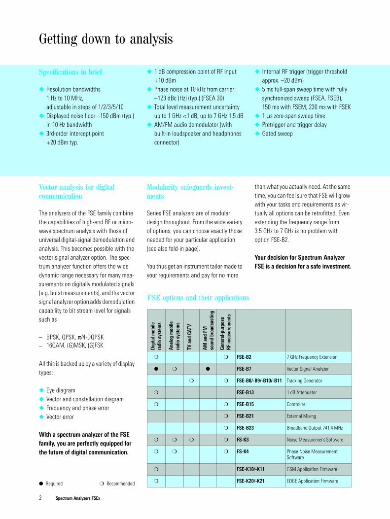
FSE options and their applications
Dig
ital m
obile
ra
dio
syst
ems
Anal
og m
obile
radi
o sy
stem
s
TV a
nd C
ATV
AM a
nd F
M
soun
d br
oadc
astin
g
Gene
ral-p
urpo
se
RF m
easu
rem
ents
FSE-B2 7 GHz Frequency Extension
FSE-B7 Vector Signal Analyzer
FSE-B8/-B9/-B10/-B11 Tracking Generator
FSE-B13 1 dB Attenuator
FSE-B15 Controller
FSE-B21 External Mixing
FSE-B23 Broadband Output 741.4 MHz
FS-K3 Noise Measurement Software
FS-K4 Phase Noise Measurement Software
FSE-K10/-K11 GSM Application Firmware
FSE-K20/-K21 EDGE Application Firmware
than what you actually need. At the same time, you can feel sure that FSE will grow with your tasks and requirements as vir-tually all options can be retrofitted. Even extending the frequency range from 3.5 GHz to 7 GHz is no problem with option FSE-B2.
Your decision for Spectrum Analyzer FSE is a decision for a safe investment.
Required Recommended
Spectrum Analyzers FSEx 3
High speed increases efficiency
The high speed of FSE increases effi-ciency in development and production:
FSE features a minimum full-span sweep time of 5 ms (FSEA/B) with a fully synchronized sweep. This means that added speed is not at the ex-pense of frequency accuracy but even enhances it
The shortest zero-span sweep time is 1 µs (100 ns/div) – ideal for high-resolution measurements on pulse edges
Up to 25 sweeps per second is an op-timal prerequisite for rapid and easy alignments and for applications in production
With its high measurement speed and great ease of operation, FSE will solve even highly complex measurement tasks in next to no time.
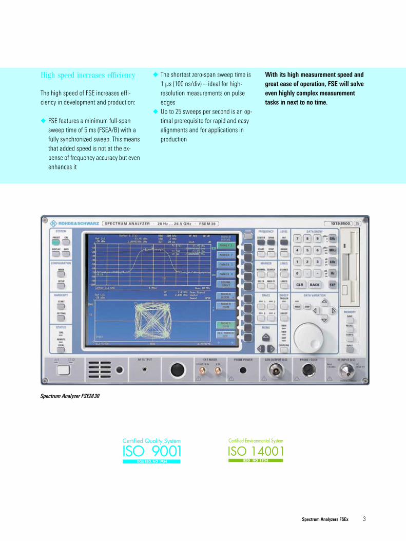
Spectrum Analyzer FSEM30
ISO 9001Certified Quality System
DQS REG. NO 1954
4 Spectrum Analyzers FSEx
FSEA 30resolution bandwidth1 Hz
FSEA 30resolution bandwidth1 MHz+10 dBm
1 dB compressionpoint
−99 dBmdisplayed noise floorof FSE at 1 MHzresolution bandwidth
typ. −159 dBmdisplayed noise floorof FSEA 30 at 1 Hz
−174 dBm (Hz)noise floor at room temperature
169 dB 109 dBdynamic range
1 MHz resolution bandwidth (1 Hz)60 dB
FSEAnoise figuretyp. 15 dB
–10–20–30–40–50–60–70 0
–40
–50
–60
–70
–120
–110
–100
–90
–80
TOI
Harmonics suppression
Mixer level [dBm]
Disp
laye
d no
ise
floor
and
inte
rmod
ulat
ion-
free
rang
e re
lativ
e to
mix
er le
vel [
dB]
Displayed noise floor (BW = 1 kHz)Displayed noise floor (BW = 10 Hz)
Displayed noise floor (BW = 1 Hz)
The features in detail ...
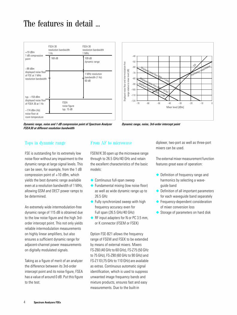
Dynamic range, noise and 1 dB compression point of Spectrum Analyzer FSEA30 at different resolution bandwidth
Dynamic range, noise, 3rd-order intercept point
Tops in dynamic range
FSE is outstanding for its extremely low noise floor without any impairment to the dynamic range at large signal levels. This can be seen, for example, from the 1 dB compression point of +10 dBm, which yields the best dynamic range available even at a resolution bandwidth of 1 MHz, allowing GSM and DECT power ramps to be determined.
An extremely wide intermodulation-free dynamic range of 115 dB is obtained due to the low noise figure and the high 3rd-order intercept point. This not only yields reliable intermodulation measurements on highly linear amplifiers, but also ensures a sufficient dynamic range for adjacent-channel power measurements on digitally modulated signals.
Taking as a figure of merit of an analyzer the difference between its 3rd-order intercept point and its noise figure, FSEA has a value of around 0 dB. Put this figure to the test.
From AF to microwave
FSEM/K 30 open up the microwave range through to 26.5 GHz/40 GHz and retain the excellent characteristics of the basic models:
Continuous full-span sweep Fundamental mixing (low noise floor)
as well as wide dynamic range up to 26.5 GHz
Fully synchronized sweep with high frequency accuracy even for Full span (26.5 GHz/40 GHz)
RF input adapters for N or PC 3.5 mm, or K connector (FSEM or FSEK)
Option FSE-B21 allows the frequency range of FSEM and FSEK to be extended by means of external mixers. Mixers FS-Z60 (40 GHz to 60 GHz), FS-Z75 (50 GHz to 75 GHz), FS-Z90 (60 GHz to 90 GHz) and FS-Z110 (75 GHz to 110 GHz) are available as extras. Continuous automatic signal identification, which is used to suppress unwanted image frequency bands and mixture products, ensures fast and easy measurements. Due to the built-in
diplexer, two-port as well as three-port mixers can be used.
The external mixer measurement function features great ease of operation:
Definition of frequency range and harmonics by selecting a wave-guide band
Definition of all important parameters for each waveguide band separately
Frequency-dependent consideration of mixer conversion loss
Storage of parameters on hard disk
Spectrum Analyzers FSEx 5
Unattained measuring convenience
FSE makes measuring easy for you through a large number of convenient test functions:
4 markers, 4 delta markers Marker functions for direct measure-
ment of– phase noise and noise power
density– NEXT MIN/PEAK, NEXT MIN/PEAK
RIGHT, NEXT MIN/PEAK LEFT– bandwidths and shape factor
Measurement of channel power, adja-cent channel power and occupied bandwidth
Frequency counter with selectable resolution
LOW NOISE, NORMAL and LOW DISTORTION modes for low-intermod-ulation and low-noise operation
Hardcopy at a keystroke Simultaneous measurement of four
active traces Level, frequency and user-definable
limit lines as evaluation help with pass/fail information
Split screen with independent mea-surement windows
Frequency accuracy – to the point
Tuning on FSE is absolutely synchronous to the reference frequency for each span including full span. This means that every point on the frequency axis is determined with the accuracy of the internal refer-ence frequency and the pixel resolution. Thus, when reducing the span for detailed signal analysis, the tiresome readjustment of the center frequency is no longer needed.
FSE in its basic configuration includes an AM/FM audio demodulator. Unknown signals can easily be identified via head-phones or the built-in loudspeaker. Mod-ulation measurements are possible using the optional Vector Signal Analyzer FSE-B7.
Limit lines facilitate checking whether results are within predefined tolerances. Virtually any number of limit lines can be defined with high accuracy by means of 50 points to meet even the most exacting requirements.
Scalar network analysis
The optional tracking generators (see data sheet for FSE-B8/9/10/11 PD 0757.3434) are an ideal tool for deter-mining frequency response, attenuation or VSWR and feature the following char-acteristics:
Wide dynamic range for attenuation measurements (up to 120 dB)
Frequency range from 9 kHz to 3.5/7 GHz
Frequency offset up to ± 200 MHz for measurements on frequency-convert-ing modules
The tracking generators with built-in I/Q modulator are ideal for generating digitally modulated signals. An external two-chan-nel Arbitrary Waveform Generator (e.g. AMIQ from Rohde&Schwarz) serves as modulation source.
By adding the optional Vector Signal Ana-lyzer FSE-B7, FSE can be expanded to a test assembly enabling direct measure-ment of the influence of amplifiers or fil-ters on phase error for instance.
Operation – as you like it
Despite their comprehensive functionali-ties the analyzers feature great ease of operation. Basic functions and frequently used help tools such as markers can be called at a keystroke. The full operating convenience based on a wide variety of evaluation routines and marker functions can be accessed via the menus.
All essential parameters and results can be seen at a glance. All test data, scale factors and setting parameters are logi-cally arranged and therefore easy to find. Setups, traces and graticules displayed in colour make for error-free analysis of complex results.
All models are equipped with a large 24 cm (9.5") TFT colour display with VGA resolution (640 x 480 pixels).
The USER key allows the FSE operation to be tailored to your specific requirements. With this key, you can compile the func-tions mainly needed for your measure-ment tasks, which does away with fre-quent menu changes and speeds up mea-surements on the whole.
Test results – perfectly documented
FSE affords uncomplicated logging of results. It supports a wide variety of print-ers such as:
Printer with HP-PCL4 and HP-PCL5 HP Deskjet/HP Laserjet Postscript
Print files cannot only be output via an interface but can also be stored on dis-kette or the internal hard disk. With PCX, WMF and HP-GL (without option
6 Spectrum Analyzers FSEx
FSE-B15) as well as BMP and WMF (with option FSE-B15) print formats being avail-able, there is no problem in further processing print files in standard text processing systems. Using Controller FSE-B15, it is particularly easy to gener-ate test reports and integrate the results. Texts can then be processed under Win-dows on FSE itself.
FSE as a controller
The optional Controller FSE-B15 provides a further VGA card, a memory extension to 64 Mbyte, a serial mouse and a key-board. With this option, WindowsNT applications, e.g. statistics programs or spreadsheet analysis, can be installed on FSE. FSE can even be linked to a network using the optional Ethernet Interface FSE-B16.
Complete setups, traces, limit lines and macros can be stored on the internal hard disk or on a diskette using the built-in 1.44 Mbyte drive.
FSE in automatic test systems
FSE is ideal for use in automatic test sys-tems, affording not only fast processing of results but also an IEC/IEEE-bus com-mand set conforming to SCPI.
Moreover, with optional Controller FSE-B15 and a second IEC/IEEE-bus card (option FSE-B17), FSE can be used as a controller for test systems, thus eliminat-ing the need for further units and saving space in the system cabinet.
Low overall costs
In designing FSE, special emphasis was placed on keeping after-sales costs to a minimum:
Temperature-controlled fans Calibration interval up to 2 years Built-in calibration routines Numerous selftest routines Modular design
... The features in detail
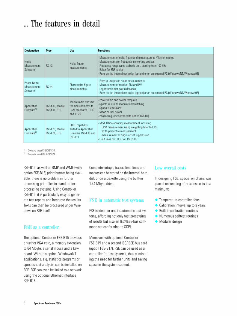
Designation Type Use Functions
Noise MeasurementSoftware
FS-K3Noise figuremeasurements
- Measurement of noise figure and temperature to Y-factor method- Measurements on frequency-converting devices- Frequency range same as basic unit, starting from 100 kHz- Editor for ENR tables- Runs on the internal controller (option) or on an external PC (WindowsNT/Windows98)
Phase Noise MeasurementSoftware
FS-K4Phase noise figuremeasurements
- Easy-to-use phase noise measurements- Measurement of residual FM and PM- Logarithmic plot over 8 decades- Runs on the internal controller (option) or on an external PC (WindowsNT/Windows98)
Application Firmware1)
1) See data sheet FSE-K10/-K11.
FSE-K10, MobileFSE-K11, BTS
Mobile radio transmit-ter measurements to GSM standards 11.10 and 11.20
- Power ramp and power template- Spectrum due to modulation/switching- Spurious emissions- Mean carrier power- Phase/frequency error (with option FSE-B7)
Application Firmware2)
2) See data sheet FSE-K20/-K21.
FSE-K20, MobileFSE-K21, BTS
EDGE capability added to Application Firmware FSE-K10 and FSE-K11
- Modulation accuracy measurement includingEVM measurement using weighting filter to ETSI95:th-percentile measurementmeasurement of origin offset suppression
- Limit lines for EDGE to ETSI05.05
Spectrum Analyzers FSEx 7
Calibration routines
Built-in calibration routines ensure that FSE remains within defined tolerances and thus maintains its accuracy of mea-surement. The routines are not performed automatically by the instrument but can be started by the user, thus avoiding ongoing measurements to be interrupted. The results of calibration routines are out-put by FSE in the form of comprehensive correction tables. Comparing these tables over an extended period of time, the user can detect changes early and take correc-tive steps in time. This enhances confi-dence in the unit’s reliability and mea-surement accuracy.
A particular asset in system applications is the internally selectable, high-precision level calibration source, which reduces the number of cables required.
Selftest – the built-in diagnostic system
The instrument selftest rapidly locates any faults down to module level. Defec-tive modules can be replaced nearly with-out adjustments or extra test equipment being required. This in conjunction with the quick spare parts service from Rohde&Schwarz reduces any repair or downtime costs that might arise. The low operating costs go easy on your budget.
Modular design – easy retrofitting of options
The modular concept of the most impor-tant options such as Vector Signal Ana-lyzer and 7 GHz Frequency Extension, as well as the alignment-free incorporation of the remaining options make it possible to retrofit the instrument with a minimum of downtime or installation costs being involved.
Quality management at Rohde&Schwarz
Lasting customer satisfaction is our pri-mary objective. The quality management system of Rohde&Schwarz meets the requirements of ISO9001 and encom-passes largely all fields of activity of the company.
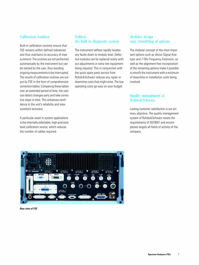
Rear view of FSE
8 Spectrum Analyzers FSEx
Applications ...
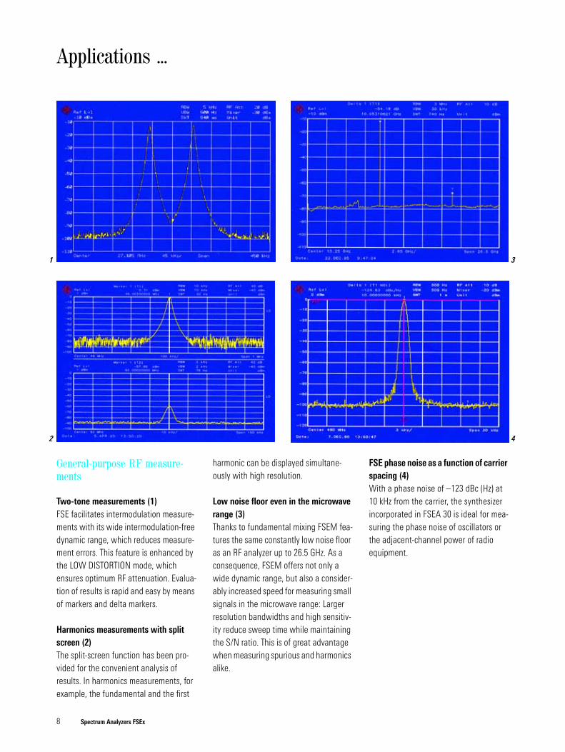
General-purpose RF measure-ments
Two-tone measurements (1)FSE facilitates intermodulation measure-ments with its wide intermodulation-free dynamic range, which reduces measure-ment errors. This feature is enhanced by the LOW DISTORTION mode, which ensures optimum RF attenuation. Evalua-tion of results is rapid and easy by means of markers and delta markers.
Harmonics measurements with split screen (2)The split-screen function has been pro-vided for the convenient analysis of results. In harmonics measurements, for example, the fundamental and the first
harmonic can be displayed simultane-ously with high resolution.
Low noise floor even in the microwave range (3)Thanks to fundamental mixing FSEM fea-tures the same constantly low noise floor as an RF analyzer up to 26.5 GHz. As a consequence, FSEM offers not only a wide dynamic range, but also a consider-ably increased speed for measuring small signals in the microwave range: Larger resolution bandwidths and high sensitiv-ity reduce sweep time while maintaining the S/N ratio. This is of great advantage when measuring spurious and harmonics alike.
FSE phase noise as a function of carrier spacing (4)With a phase noise of –123 dBc (Hz) at 10 kHz from the carrier, the synthesizer incorporated in FSEA 30 is ideal for mea-suring the phase noise of oscillators or the adjacent-channel power of radio equipment.
1
2
3
4
Spectrum Analyzers FSEx 9
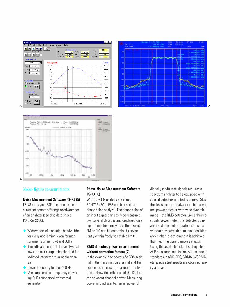
Noise figure measurements
Noise Measurement Software FS-K3 (5)FS-K3 turns your FSE into a noise mea-surement system offering the advantages of an analyzer (see also data sheet PD 0757.2380):
Wide variety of resolution bandwidths for every application, even for mea-surements on narrowband DUTs
If results are doubtful, the analyzer al-lows the test setup to be checked for radiated interference or nonharmon-ics
Lower frequency limit of 100 kHz Measurements on frequency-convert-
ing DUTs supported by external generator
Phase Noise Measurement Software FS-K4 (6) With FS-K4 (see also data sheet PD 0757.4201), FSE can be used as a phase noise analyzer. The phase noise of an input signal can easily be measured over several decades and displayed on a logarithmic frequency axis. The residual FM or PM can be determined conven-iently within freely selectable limits.
RMS detector: power measurement without correction factors (7) In the example, the power of a CDMA sig-nal in the transmission channel and the adjacent channels is measured. The two traces show the influence of the DUT on the adjacent-channel power. Measuring power and adjacent-channel power of
digitally modulated signals requires a spectrum analyzer to be equipped with special detectors and test routines. FSE is the first spectrum analyzer that features a real power detector with wide dynamic range – the RMS detector. Like a thermo-couple power meter, this detector guar-antees stable and accurate test results without any correction factors. Consider-ably higher test throughput is achieved than with the usual sample detector. Using the available default settings for ACP measurements in line with common standards (NADC, PDC, CDMA, WCDMA, etc) precise test results are obtained eas-ily and fast.
5
6
7
10 Spectrum Analyzers FSEx
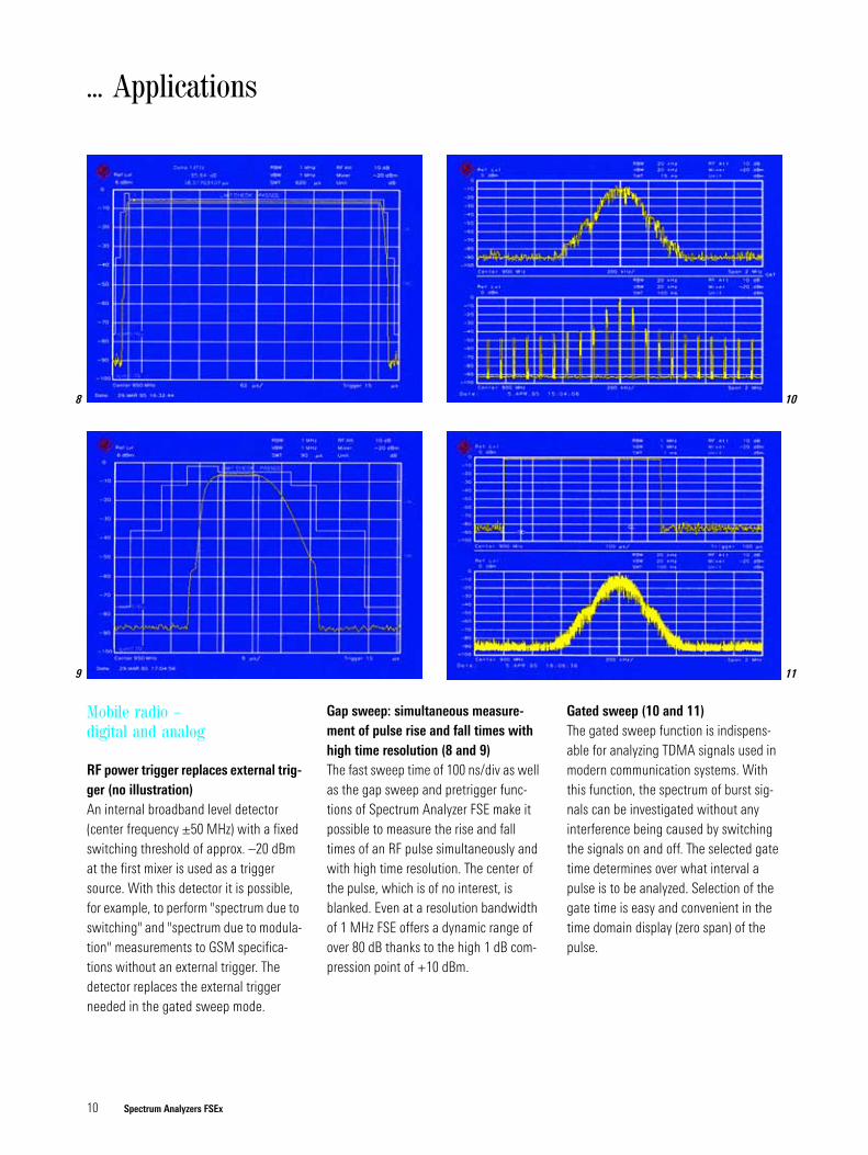
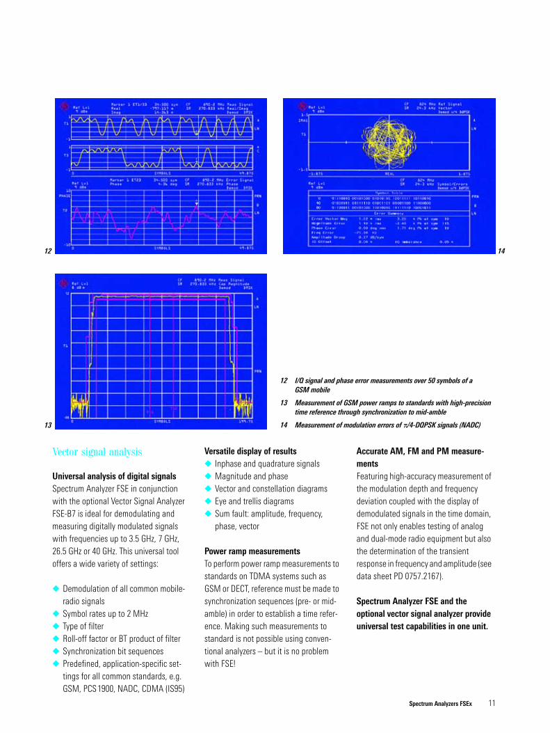
Gap sweep: simultaneous measure-ment of pulse rise and fall times with high time resolution (8 and 9)The fast sweep time of 100 ns/div as well as the gap sweep and pretrigger func-tions of Spectrum Analyzer FSE make it possible to measure the rise and fall times of an RF pulse simultaneously and with high time resolution. The center of the pulse, which is of no interest, is blanked. Even at a resolution bandwidth of 1 MHz FSE offers a dynamic range of over 80 dB thanks to the high 1 dB com-pression point of +10 dBm.
Gated sweep (10 and 11)The gated sweep function is indispens-able for analyzing TDMA signals used in modern communication systems. With this function, the spectrum of burst sig-nals can be investigated without any interference being caused by switching the signals on and off. The selected gate time determines over what interval a pulse is to be analyzed. Selection of the gate time is easy and convenient in the time domain display (zero span) of the pulse.
Mobile radio – digital and analog
RF power trigger replaces external trig-ger (no illustration)An internal broadband level detector (center frequency ±50 MHz) with a fixed switching threshold of approx. –20 dBm at the first mixer is used as a trigger source. With this detector it is possible, for example, to perform "spectrum due to switching" and "spectrum due to modula-tion" measurements to GSM specifica-tions without an external trigger. The detector replaces the external trigger needed in the gated sweep mode.
... Applications
8
9
10
11
Spectrum Analyzers FSEx 11
Vector signal analysis
Universal analysis of digital signalsSpectrum Analyzer FSE in conjunction with the optional Vector Signal Analyzer FSE-B7 is ideal for demodulating and measuring digitally modulated signals with frequencies up to 3.5 GHz, 7 GHz, 26.5 GHz or 40 GHz. This universal tool offers a wide variety of settings:
Demodulation of all common mobile-radio signals
Symbol rates up to 2 MHz Type of filter Roll-off factor or BT product of filter Synchronization bit sequences Predefined, application-specific set-
tings for all common standards, e.g. GSM, PCS1900, NADC, CDMA (IS95)
Versatile display of results Inphase and quadrature signals Magnitude and phase Vector and constellation diagrams Eye and trellis diagrams Sum fault: amplitude, frequency,
phase, vector
Power ramp measurementsTo perform power ramp measurements to standards on TDMA systems such as GSM or DECT, reference must be made to synchronization sequences (pre- or mid-amble) in order to establish a time refer-ence. Making such measurements to standard is not possible using conven-tional analyzers – but it is no problem with FSE!
Accurate AM, FM and PM measure-mentsFeaturing high-accuracy measurement of the modulation depth and frequency deviation coupled with the display of demodulated signals in the time domain, FSE not only enables testing of analog and dual-mode radio equipment but also the determination of the transient response in frequency and amplitude (see data sheet PD 0757.2167).
Spectrum Analyzer FSE and the optional vector signal analyzer provide universal test capabilities in one unit.
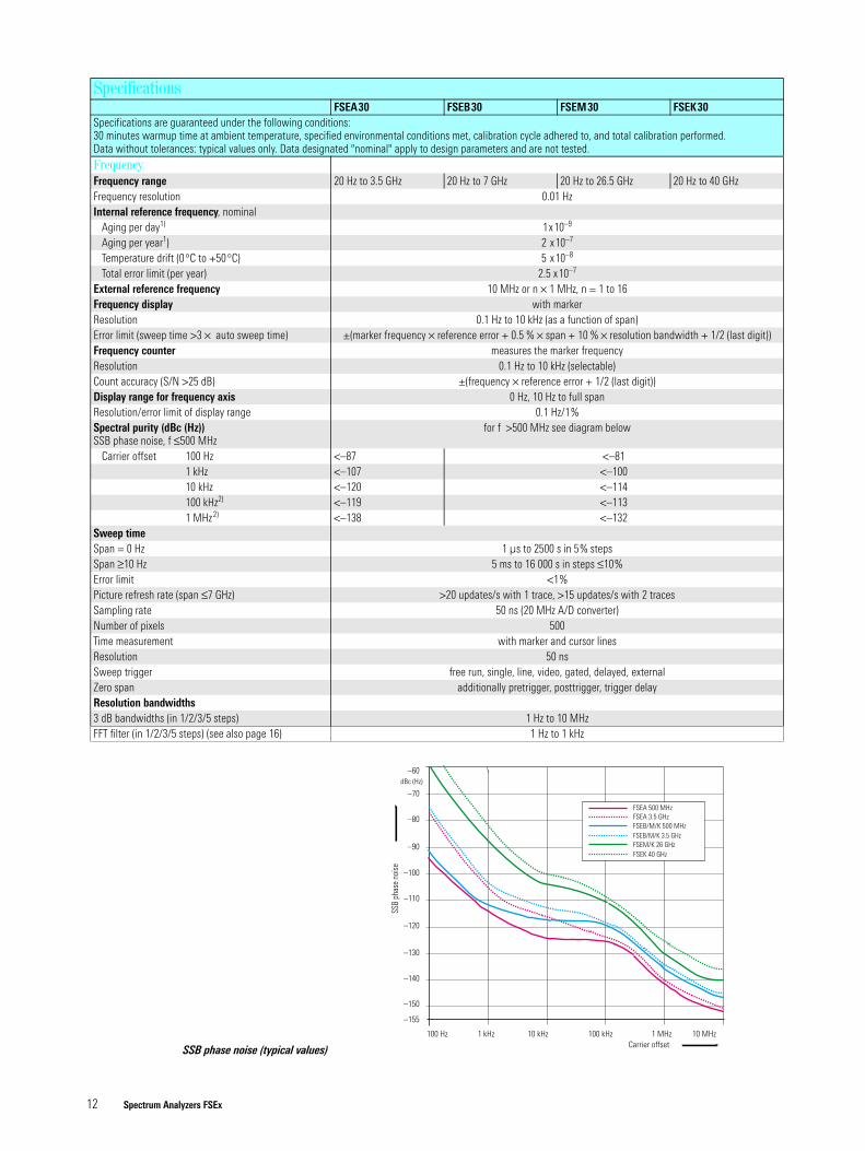
12 I/Q signal and phase error measurements over 50 symbols of a GSM mobile
13 Measurement of GSM power ramps to standards with high-precisiontime reference through synchronization to mid-amble
14 Measurement of modulation errors of π/4-DQPSK signals (NADC)
12
13
14
12 Spectrum Analyzers FSEx
Specifications
FSEA30 FSEB30 FSEM30 FSEK30 Specifications are guaranteed under the following conditions:30 minutes warmup time at ambient temperature, specified environmental conditions met, calibration cycle adhered to, and total calibration performed. Data without tolerances: typical values only. Data designated "nominal" apply to design parameters and are not tested.FrequencyFrequency range 20 Hz to 3.5 GHz 20 Hz to 7 GHz 20 Hz to 26.5 GHz 20 Hz to 40 GHzFrequency resolution 0.01 HzInternal reference frequency, nominal
Aging per day1) 1x10⁻⁹
Aging per year1) 2 x10⁻⁷
Temperature drift (0°C to +50°C) 5 x10⁻⁸
Total error limit (per year) 2.5 x10⁻⁷
External reference frequency 10 MHz or n × 1 MHz, n = 1 to 16Frequency display with markerResolution 0.1 Hz to 10 kHz (as a function of span)Error limit (sweep time >3 × auto sweep time) ±(marker frequency × reference error + 0.5 % × span + 10 % × resolution bandwidth + 1/2 (last digit))Frequency counter measures the marker frequency Resolution 0.1 Hz to 10 kHz (selectable)Count accuracy (S/N >25 dB) ±(frequency × reference error + 1/2 (last digit))Display range for frequency axis 0 Hz, 10 Hz to full spanResolution/error limit of display range 0.1 Hz/1%Spectral purity (dBc (Hz)) SSB phase noise, f ≤500 MHz
for f >500 MHz see diagram below
Carrier offset 100 Hz <–87 <–811 kHz <–107 <–10010 kHz <–120 <–114100 kHz2) <–119 <–1131 MHz2) <–138 <–132
Sweep timeSpan = 0 Hz 1 µs to 2500 s in 5% stepsSpan ≥10 Hz 5 ms to 16 000 s in steps ≤10%Error limit <1%Picture refresh rate (span ≤7 GHz) >20 updates/s with 1 trace, >15 updates/s with 2 tracesSampling rate 50 ns (20 MHz A/D converter)Number of pixels 500Time measurement with marker and cursor linesResolution 50 nsSweep trigger free run, single, line, video, gated, delayed, externalZero span additionally pretrigger, posttrigger, trigger delayResolution bandwidths3 dB bandwidths (in 1/2/3/5 steps) 1 Hz to 10 MHzFFT filter (in 1/2/3/5 steps) (see also page 16) 1 Hz to 1 kHz
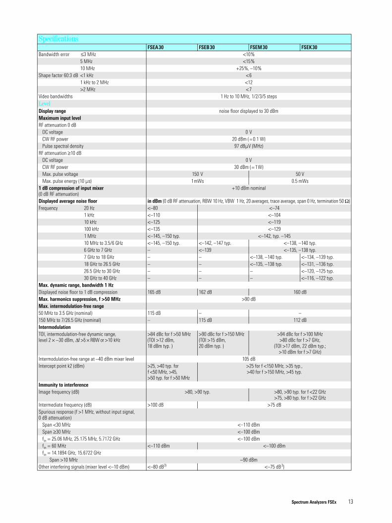
SSB phase noise (typical values)
100 Hz 1 kHz 10 kHz 100 kHz 10 MHz1 MHzCarrier offset
dBc (Hz)
SSB
phas
e no
ise
–70
–80
–90
–100
–110
–120
–130
–140
–150
–155
–60
FSEB/M/K 3.5 GHz
FSEA 500 MHzFSEA 3.5 GHzFSEB/M/K 500 MHz
FSEM/K 26 GHzFSEK 40 GHz
Spectrum Analyzers FSEx 13
Bandwidth error ≤3 MHz <10%5 MHz <15%10 MHz +25%, –10%
Shape factor 60:3 dB <1 kHz <61 kHz to 2 MHz <12>2 MHz <7
Video bandwidths 1 Hz to 10 MHz, 1/2/3/5 stepsLevelDisplay range noise floor displayed to 30 dBmMaximum input levelRF attenuation 0 dB
DC voltage 0 VCW RF power 20 dBm (=0.1 W)Pulse spectral density 97 dBµV (MHz)
RF attenuation ≥10 dBDC voltage 0 VCW RF power 30 dBm (=1W)Max. pulse voltage 150 V 50 VMax. pulse energy (10 µs) 1mWs 0.5 mWs
1 dB compression of input mixer (0 dB RF attenuation)
+10 dBm nominal
Displayed average noise floor in dBm (0 dB RF attenuation, RBW 10 Hz, VBW 1 Hz, 20 averages, trace average, span 0 Hz, termination 50 Ω)Frequency 20 Hz <–80 <–74
1 kHz <–110 <–10410 kHz <–125 <–119100 kHz <–135 <–1291 MHz <–145, –150 typ. <–142, typ. –14510 MHz to 3.5/6 GHz <–145, –150 typ. <–142, –147 typ. <–138, –140 typ. 6 GHz to 7 GHz – <–139 <–135, –138 typ. 7 GHz to 18 GHz – – <–138, –140 typ. <–134, –139 typ. 18 GHz to 26.5 GHz – – <–135, –138 typ. <–131, –136 typ. 26.5 GHz to 30 GHz – – – <–120, –125 typ. 30 GHz to 40 GHz – – – <–116, –122 typ.
Max. dynamic range, bandwidth 1 HzDisplayed noise floor to 1 dB compression 165 dB 162 dB 160 dBMax. harmonics suppression, f >50 MHz >90 dBMax. intermodulation-free range50 MHz to 3.5 GHz (nominal) 115 dB – –150 MHz to 7/26.5 GHz (nominal) – 115 dB 112 dBIntermodulationTOI, intermodulation-free dynamic range, level 2 × −30 dBm, ∆f >5 × RBW or >10 kHz
>84 dBc for f >50 MHz (TOI >12 dBm, 18 dBm typ. )
>90 dBc for f >150 MHz (TOI >15 dBm, 20 dBm typ. )
>94 dBc for f >100 MHz>80 dBc for f >7 GHz,
(TOI >17 dBm, 22 dBm typ.; >10 dBm for f >7 GHz)
Intermodulation-free range at –40 dBm mixer level 105 dBIntercept point k2 (dBm) >25, >40 typ. for
f <50 MHz, >45, >50 typ. for f >50 MHz
>25 for f <150 MHz, >35 typ., >40 for f >150 MHz, >45 typ.
Immunity to interferenceImage frequency (dB) >80, >90 typ. >80, >90 typ. for f <22 GHz
>75, >80 typ. for f >22 GHzIntermediate frequency (dB) >100 dB >75 dBSpurious response (f >1 MHz, without input signal, 0 dB attenuation)
Span <30 MHz <–110 dBmSpan ≥30 MHz <–100 dBmfin = 25.06 MHz, 25.175 MHz, 5.7172 GHz <–100 dBmfin = 60 MHz <–110 dBm <–100 dBmfin = 14.1894 GHz, 15.6722 GHz
Span >10 MHz −90 dBmOther interfering signals (mixer level <–10 dBm) <–80 dB3) <–75 dB3)
SpecificationsFSEA30 FSEB30 FSEM30 FSEK30
14 Spectrum Analyzers FSEx
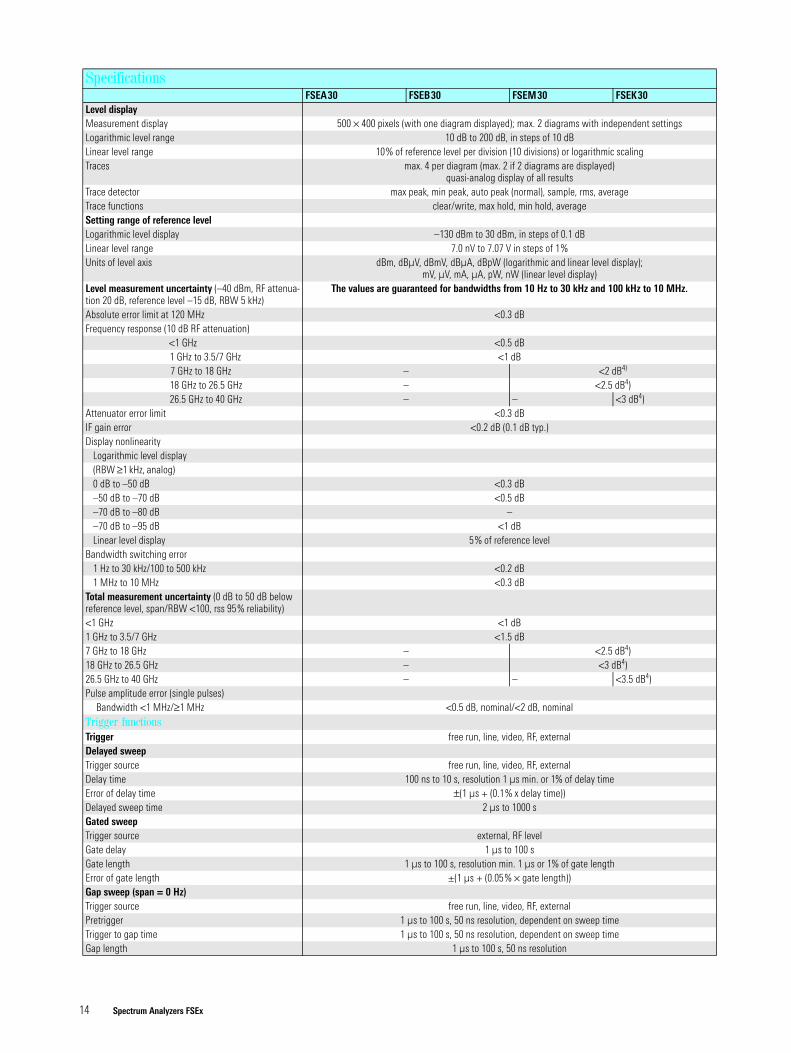
Level displayMeasurement display 500 × 400 pixels (with one diagram displayed); max. 2 diagrams with independent settingsLogarithmic level range 10 dB to 200 dB, in steps of 10 dBLinear level range 10% of reference level per division (10 divisions) or logarithmic scalingTraces max. 4 per diagram (max. 2 if 2 diagrams are displayed)
quasi-analog display of all resultsTrace detector max peak, min peak, auto peak (normal), sample, rms, averageTrace functions clear/write, max hold, min hold, averageSetting range of reference levelLogarithmic level display –130 dBm to 30 dBm, in steps of 0.1 dBLinear level range 7.0 nV to 7.07 V in steps of 1%Units of level axis dBm, dBµV, dBmV, dBµA, dBpW (logarithmic and linear level display);
mV, µV, mA, µA, pW, nW (linear level display)Level measurement uncertainty (–40 dBm, RF attenua-tion 20 dB, reference level –15 dB, RBW 5 kHz)
The values are guaranteed for bandwidths from 10 Hz to 30 kHz and 100 kHz to 10 MHz.
Absolute error limit at 120 MHz <0.3 dBFrequency response (10 dB RF attenuation)
<1 GHz <0.5 dB1 GHz to 3.5/7 GHz <1 dB7 GHz to 18 GHz – <2 dB4)
18 GHz to 26.5 GHz – <2.5 dB4)26.5 GHz to 40 GHz – – <3 dB4)
Attenuator error limit <0.3 dBIF gain error <0.2 dB (0.1 dB typ.)Display nonlinearity
Logarithmic level display(RBW ≥1 kHz, analog)0 dB to –50 dB <0.3 dB–50 dB to –70 dB <0.5 dB–70 dB to –80 dB ––70 dB to –95 dB <1 dBLinear level display 5% of reference level
Bandwidth switching error1 Hz to 30 kHz/100 to 500 kHz <0.2 dB1 MHz to 10 MHz <0.3 dB
Total measurement uncertainty (0 dB to 50 dB below reference level, span/RBW <100, rss 95% reliability)<1 GHz <1 dB1 GHz to 3.5/7 GHz <1.5 dB7 GHz to 18 GHz – <2.5 dB4)18 GHz to 26.5 GHz – <3 dB4)26.5 GHz to 40 GHz – – <3.5 dB4)Pulse amplitude error (single pulses)
Bandwidth <1 MHz/≥1 MHz <0.5 dB, nominal/<2 dB, nominalTrigger functionsTrigger free run, line, video, RF, externalDelayed sweepTrigger source free run, line, video, RF, externalDelay time 100 ns to 10 s, resolution 1 µs min. or 1% of delay timeError of delay time ±(1 µs + (0.1% x delay time))Delayed sweep time 2 µs to 1000 sGated sweepTrigger source external, RF levelGate delay 1 µs to 100 sGate length 1 µs to 100 s, resolution min. 1 µs or 1% of gate lengthError of gate length ±(1 µs + (0.05% × gate length))Gap sweep (span = 0 Hz)Trigger source free run, line, video, RF, externalPretrigger 1 µs to 100 s, 50 ns resolution, dependent on sweep timeTrigger to gap time 1 µs to 100 s, 50 ns resolution, dependent on sweep timeGap length 1 µs to 100 s, 50 ns resolution
SpecificationsFSEA30 FSEB30 FSEM30 FSEK30
Spectrum Analyzers FSEx 15
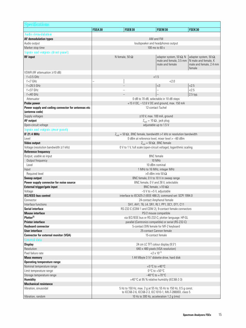
Audio demodulationAF demodulation types AM and FMAudio output loudspeaker and headphones outputMarker stop time 100 ms to 60 sInputs and outputs (front panel)RF input N female, 50 Ω adapter system, 50 Ω, N
male and female, 3.5 mm male and female
adapter system, 50 Ω, N male and female, K male and female, 2.4 mm female
VSWR (RF attenuation ≥10 dB)f <3.5 GHz <1.5f <7 GHz – <2.0f <26.5 GHz – <3 <2.5f <37 GHz – – <2.5f <40 GHz – – 2.5 typ. Attenuator 0 dB to 70 dB, selectable in 10 dB steps
Probe power +15 V DC, –12.6 V DC and ground, max. 150 mAPower supply and coding connector for antennas etc (antenna code)
12-contact Tuchel
Supply voltages ±10 V, max. 100 mA, groundAF output Zout = 10 Ω , jack plugOpen-circuit voltage adjustable up to 1.5 VInputs and outputs (rear panel)IF 21.4 MHz Zout = 50 Ω , BNC female, bandwidth >1 kHz or resolution bandwidthLevel 0 dBm at reference level, mixer level > –60 dBmVideo output Zout = 50 Ω , BNC femaleVoltage (resolution bandwidth ≥1 kHz) 0 V to 1 V, full scale (open-circuit voltage); logarithmic scalingReference frequencyOutput, usable as input BNC female
Output frequency 10 MHzLevel 10 dBm nominal
Input 1 MHz to 16 MHz, integer MHzRequired level >0 dBm into 50 Ω
Sweep output BNC female, 0 V to 10 V in sweep rangePower supply connector for noise source BNC female, 0 V and 28 V, selectableExternal trigger/gate input BNC female, >10 kΩVoltage –5 V to +5 V, adjustableIEC/IEEE-bus control interface to IEC625-2 (IEEE 488.2), command set: SCPI 1994.0Connector 24-contact Amphenol femaleInterface functions SH1, AH1, T6, L4, SR1, RL1, PP1, DC1, DT1, C11Serial interface RS-232-C (COM 1 and COM 2), 9-contact female connectorsMouse interface PS/2 mouse compatiblePlotter5) via IEC/IEEE bus or RS-232-C; plotter language: HP-GLPrinter interface parallel (Centronics compatible) or serial (RS-232-C)Keyboard connector 5-contact DIN female for MF-2 keyboardUser interface 25-contact Cannon femaleConnector for external monitor (VGA) 15-contact femaleGeneral dataDisplay 24 cm LC TFT colour display (9.5")Resolution 640 × 480 pixels (VGA resolution)Pixel failure rate <2 x 10⁻⁵
Mass memory 1.44 Mbyte 3 ½" diskette drive, hard diskOperating temperature rangeNominal temperature range +5°C to +40°CLimit temperature range 0°C to +50°CStorage temperature range –40°C to +70°CHumidity +40°C at 95 % relative humidity (IEC68-2-3)Mechanical resistanceVibration, sinusoidal 5 Hz to 150 Hz, max. 2 g at 55 Hz; 55 Hz to 150 Hz, 0.5 g const.
to IEC68-2-6, IEC68-2-3, IEC1010-1, MIL-T-28800D, class 5Vibration, random 10 Hz to 300 Hz, acceleration 1.2 g (rms)
SpecificationsFSEA30 FSEB30 FSEM30 FSEK30
Spectrum Analyzers FSEx 16
FFT filter
Analog filter
100 000
10 000
1000
100
10
1
0,1
0,011 3 10 100 30030
Sweep time for 10 kHz Span
Swee
p tim
e in
s
RBW in Hz
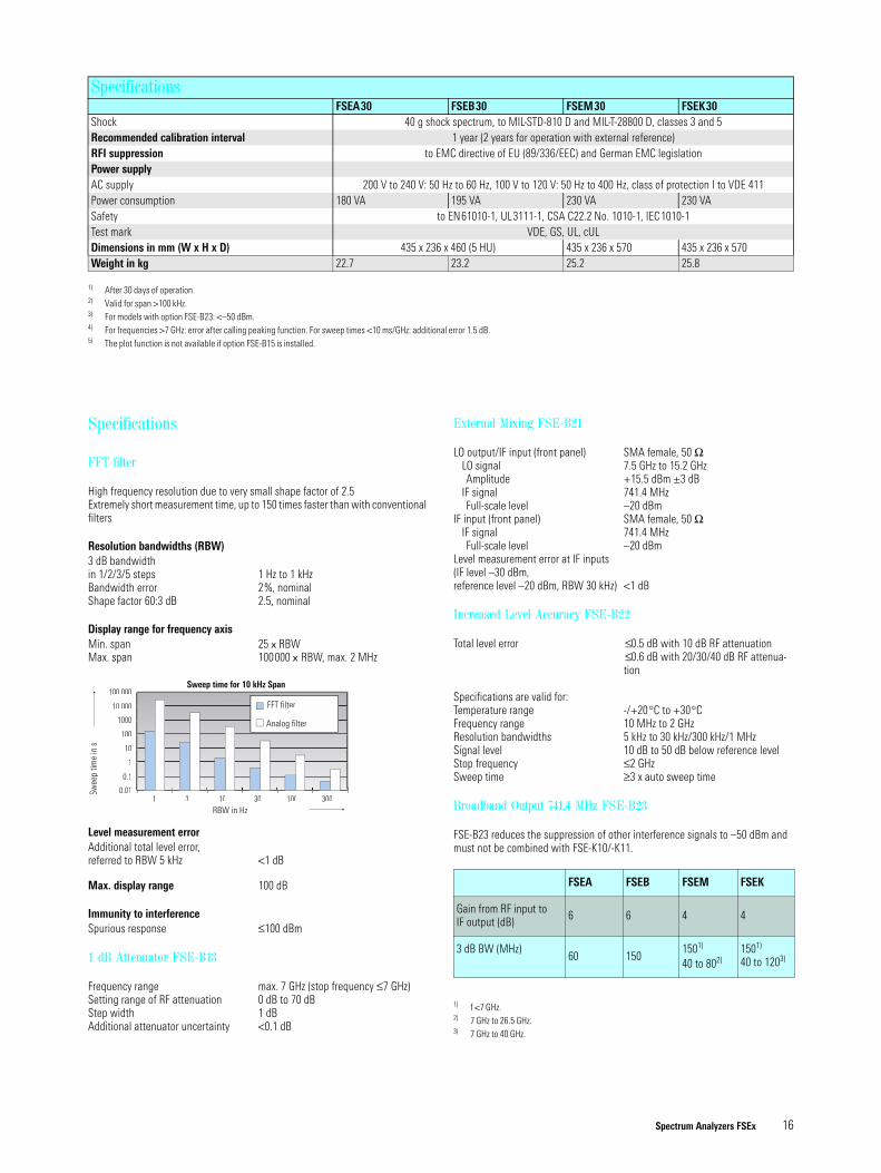
Specifications
FFT filter
High frequency resolution due to very small shape factor of 2.5Extremely short measurement time, up to 150 times faster than with conventional filters
Resolution bandwidths (RBW)3 dB bandwidthin 1/2/3/5 steps 1 Hz to 1 kHzBandwidth error 2%, nominalShape factor 60:3 dB 2.5, nominal
Display range for frequency axisMin. span 25 x RBWMax. span 100000 x RBW, max. 2 MHz
Level measurement errorAdditional total level error, referred to RBW 5 kHz <1 dB
Max. display range 100 dB
Immunity to interferenceSpurious response ≤100 dBm
1 dB Attenuator FSE-B13
Frequency range max. 7 GHz (stop frequency ≤7 GHz)Setting range of RF attenuation 0 dB to 70 dBStep width 1 dBAdditional attenuator uncertainty <0.1 dB
External Mixing FSE-B21
LO output/IF input (front panel) SMA female, 50 ΩLO signal 7.5 GHz to 15.2 GHzAmplitude +15.5 dBm ±3 dB
IF signal 741.4 MHzFull-scale level –20 dBm
IF input (front panel) SMA female, 50 ΩIF signal 741.4 MHzFull-scale level –20 dBm
Level measurement error at IF inputs (IF level –30 dBm,reference level –20 dBm, RBW 30 kHz) <1 dB
Increased Level Accuracy FSE-B22
Total level error ≤0.5 dB with 10 dB RF attenuation≤0.6 dB with 20/30/40 dB RF attenua-tion
Specifications are valid for:Temperature range -/+20°C to +30°CFrequency range 10 MHz to 2 GHzResolution bandwidths 5 kHz to 30 kHz/300 kHz/1 MHzSignal level 10 dB to 50 dB below reference levelStop frequency ≤2 GHzSweep time ≥3 x auto sweep time
Broadband Output 741.4 MHz FSE-B23
FSE-B23 reduces the suppression of other interference signals to –50 dBm and must not be combined with FSE-K10/-K11.
FSEA FSEB FSEM FSEK
Gain from RF input to IF output (dB) 6 6 4 4
3 dB BW (MHz)60 150
1501)
40 to 802)
1) f <7 GHz.2) 7 GHz to 26.5 GHz.
1501)
40 to 1203)
3) 7 GHz to 40 GHz.
Shock 40 g shock spectrum, to MIL-STD-810 D and MIL-T-28800 D, classes 3 and 5Recommended calibration interval 1 year (2 years for operation with external reference)RFI suppression to EMC directive of EU (89/336/EEC) and German EMC legislationPower supplyAC supply 200 V to 240 V: 50 Hz to 60 Hz, 100 V to 120 V: 50 Hz to 400 Hz, class of protection I to VDE 411Power consumption 180 VA 195 VA 230 VA 230 VASafety to EN61010-1, UL3111-1, CSA C22.2 No. 1010-1, IEC1010-1Test mark VDE, GS, UL, cULDimensions in mm (W x H x D) 435 x 236 x 460 (5 HU) 435 x 236 x 570 435 x 236 x 570 Weight in kg 22.7 23.2 25.2 25.8
1) After 30 days of operation.2) Valid for span >100 kHz.3) For models with option FSE-B23: <–50 dBm.4) For frequencies >7 GHz: error after calling peaking function. For sweep times <10 ms/GHz: additional error 1.5 dB.5) The plot function is not available if option FSE-B15 is installed.
SpecificationsFSEA30 FSEB30 FSEM30 FSEK30
Spectrum Analyzers FSEx 17
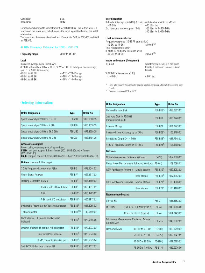
Connector BNCImpedance 50 Ω
For maximum bandwidth set instrument to 10 MHz RBW. The output level is a function of the mixer level, which equals the input signal level minus the set RF attenuation.The typical loss between mixer level and IF output is 2 dB for FSEM/K, and 0 dB for FSEA/B.
44 GHz Frequency Extension for FSEK FSE-B24
Frequency range 20 Hz to 44 GHz
LevelDisplayed average noise level (DANL)(0 dB RF attenuation, RBW = 10 Hz, VBW = 1 Hz, 20 averages, trace average, span 0 Hz, 50 Ω termination)40 GHz to 42 GHz <–112, –128 dBm typ. 42 GHz to 43 GHz <–108, –113 dBm typ. 43 GHz to 44 GHz <–105, –110 dBm typ.
Intermodulation3rd-order intercept point (TOI) ∆ f >5 x resolution bandwidth or >10 kHz
>40 GHz +15 dBm typ.2nd harmonic intercept point (SHI) >25 dBm for f <150 MHz
>40 dBm for f >150 MHz
Level measurement errorFrequency response (10 dB RF attenuation)
40 GHz to 44 GHz <4.0 dB1)2)
Total measurement error (0 dB to 50 dB below reference level)
40 GHz to 44 GHz <4.5 dB1)2)
Inputs and outputs (front panel)RF input adapter system, 50 Ω, N male und
female, K male und female, 2.4 mm female
VSWR (RF attenuation >0 dB)f >40 GHz <3.0:1 typ.
1) Error after running the preselector peaking function. For sweep <10 ms/GHz: additional error 1.5 dB.
2) Temperature range 20°C to 35°C.
Ordering information
Order designation Type Order No.
Spectrum Analyzer 20 Hz to 3.5 GHz FSEA30 1065.6000.35
Spectrum Analyzer 20 Hz to 7 GHz FSEB30 1066.3010.35
Spectrum Analyzer 20 Hz to 26.5 GHz FSEM30 1079.8500.35
Spectrum Analyzer 20 Hz to 40 GHz FSEK30 1088.3494.35
Accessories supplied Power cable, operating manual, spare fuses;FSEM: test-port adapter 3.5 mm female (1021.0512.00) and N female (1021.0535.00)FSEK: test-port adapter K female (1036.4790.00) and N female (1036.4777.00)
Options (see also fold-in page)
7 GHz Frequency Extension for FSEA FSE-B2 1073.5044.02
Vector Signal Analyzer FSE-B71) 1066.4317.03
Tracking Generator 3.5 GHz FSE-B81) 1066.4469.02
3.5 GHz with I/Q modulator FSE-B91) 1066.4617.02
7 GHz FSE-B101) 1066.4769.02
7 GHz with I/Q modulator FSE-B111) 1066.4917.02
Switchable Attenuator for Tracking Generator FSE-B122) 1066.5065.02
1 dB Attenuator FSE-B132)3) 1119.6499.02
Controller for FSE (mouse and keyboard included)
FSE-B154) 1073.5696.06
Ethernet Interface 15-contact AUI connector FSE-B165) 1073.5973.02
Thin-wire BNC connector FSE-B165) 1073.5973.03
RJ-45 connector (twisted pair) FSE-B165) 1073.5973.04
2nd IEC/IEEE-Bus Interface for FSE FSE-B175) 1066.4017.02
Removable Hard Disk FSE-B184) 1088.6993.02
2nd Hard Disk for FSE-B18 (firmware included)
FSE-B19 1088.7248.02
External Mixing FSE-B21 1084.7243.02
Increased Level Accuracy up to 2 GHz FSE-B224) 1106.3480.02
Broadband Output 741.4 MHz FSE-B234) 1088.7348.02
44 GHz Frequency Extension for FSEK FSE-B244) 1106.3680.02
Software
Noise Measurement Software, Windows FS-K31) 1057.3028.02
Phase Noise Measurement Software, Windows FS-K41) 1108.0088.02
GSM Application Firmware Mobile station FSE-K101) 1057.3092.02
Base station FSE-K111) 1057.3392.02
EDGE Application Firmware Mobile station FSE-K201) 1106.4086.02
Base station FSE-K211) 1106.4186.02
Recommended extras
Service Kit FSE-Z1 1066.3862.02
DC Block 5 MHz to 7000 MHz (type N) FSE-Z3 4010.3895.00
10 kHz to 18 GHz (type N) FSE-Z4 1084.7443.02
Microwave Measurement Cable and Adapter Set for FSEM
FSE-Z15 1046.2002.02
Harmonic Mixer 40 GHz to 60 GHz FS-Z601) 1089.0799.02
50 GHz to 75 GHz FS-Z751) 1089.0847.02
60 GHZ to 90 GHz FS-Z901) 1089.0899.02
75 GHZ to 110 GHz FS-Z1101) 1089.0976.00
Order designation Type Order No.
Prin
ted
in G
erm
any
0501
(Bi k
o)
ROHDE&SCHWARZ GmbH & Co. KG ⋅ Mühldorfstraße 15 ⋅ 81671 München ⋅ Germany ⋅ P.O.B. 8014 69 ⋅ 81614 München ⋅ Germany ⋅ Telephone +49894129-0
www.rohde-schwarz.com ⋅ Customer Support: Tel. +491805124242, Fax +4989 4129-13777, E-mail: [email protected]
PD 0
757.
1519
.28
⋅ Spe
ctru
m A
naly
zers
FSE
x ⋅ Tr
ade
nam
es a
re tr
adem
arks
of t
he o
wne
rs ⋅
Subj
ect t
o ch
ange
⋅ Da
ta w
ithou
t tol
eran
ces:
typi
cal v
alue
s
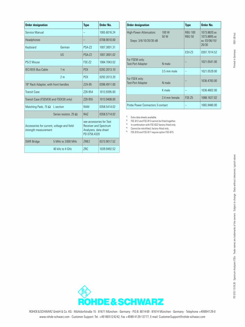
Service Manual – 1065.6016.24
Headphones – 0708.9010.00
Keyboard German PSA-Z2 1007.3001.31
US PSA-Z2 1007.3001.02
PS/2 Mouse FSE-Z2 1084.7043.02
IEC/IEEE-Bus Cable 1 m PCK 0292.2013.10
2 m PCK 0292.2013.20
19" Rack Adapter, with front handles ZZA-95 0396.4911.00
Transit Case ZZK-954 1013.9395.00
Transit Case (FSEM30 and FSEK30 only) ZZK-955 1013.9408.00
Matching Pads, 75 Ω L section RAM 0358.5414.02
Series resistor, 25 Ω RAZ 0358.5714.02
Accessories for current, voltage and field-strength measurement
see accessories for Test Receiver and Spectrum Analyzers, data sheet PD 0756.4320
SWR Bridge 5 MHz to 3000 MHz ZRB2 0373.9017.52
40 kHz to 4 GHz ZRC 1039.9492.52
Order designation Type Order No.
High-Power Attenuators 100 W50 W
Steps: 3/6/10/20/30 dB
RBU 100RBU 50
1073.8820.xx1073.8895.xxxx: 03/06/10/20/30
ESV-Z3 0397.7014.52
For FSEM only: Test-Port Adapter N male
– 1021.0541.00
3.5 mm male – 1021.0529.00
For FSEK only: Test-Port Adapter N male
– 1036.4783.00
K male – 1036.4802.00
2.4 mm female FSE-Z5 1088.1627.02
Probe Power Connectors 3-contact – 1065.9480.00
1) Extra data sheets available.2) FSE-B12 and FSE-B13 cannot be fitted together.3) In combination with FSE-B22 factory-fitted only.4) Cannot be retrofitted, factory-fitted only.5) FSE-B16 and FSE-B17 require option FSE-B15.
Order designation Type Order No.