E.T. Design Study Harald Lück. 3 main noise sources Thermal Noise Seismic Shot Noise.
http://www.ia.omron.com/ 1(c)Copyright OMRON Corporation 2007 All Rights Reserved.
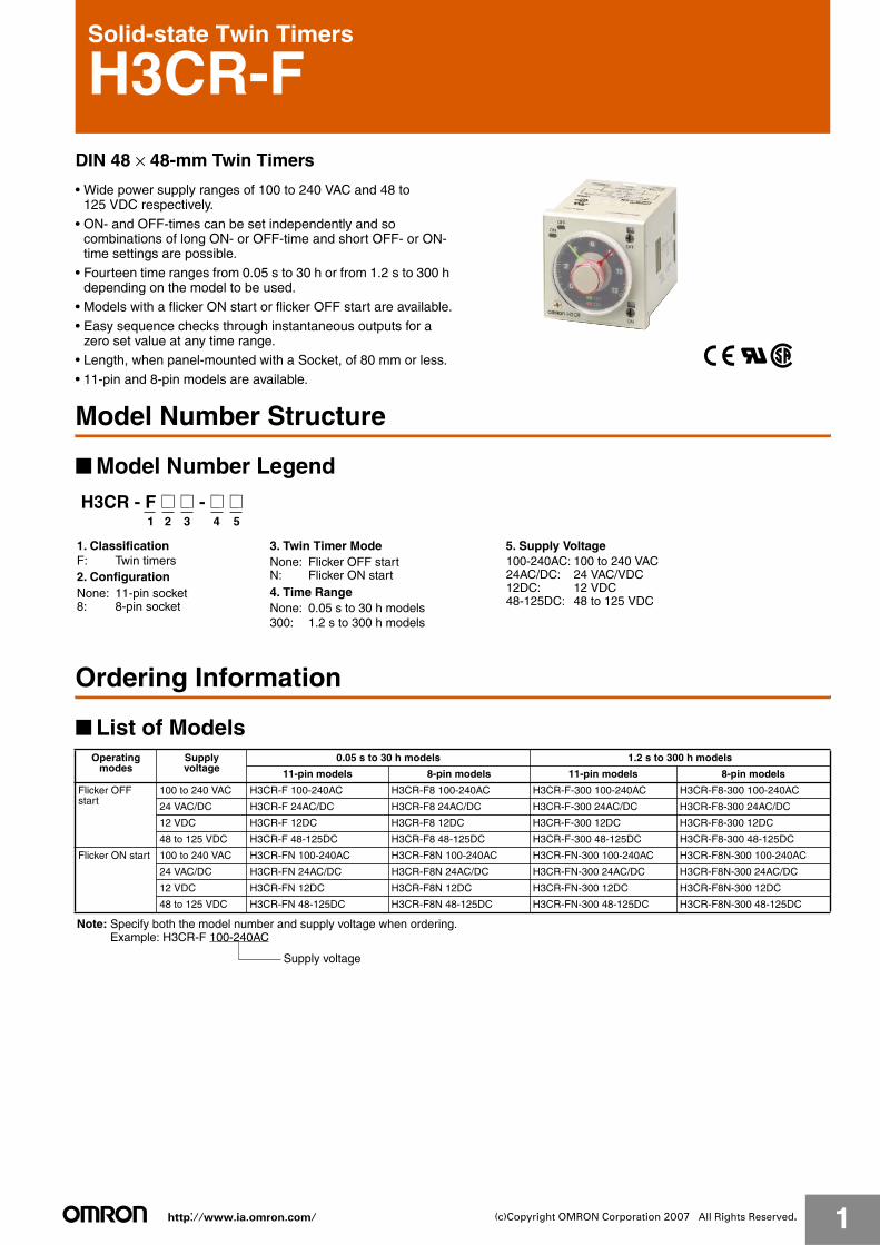
Solid-state Twin Timers
H3CR-FDIN 48 × 48-mm Twin Timers
• Wide power supply ranges of 100 to 240 VAC and 48 to 125 VDC respectively.
• ON- and OFF-times can be set independently and so combinations of long ON- or OFF-time and short OFF- or ON-time settings are possible.
• Fourteen time ranges from 0.05 s to 30 h or from 1.2 s to 300 h depending on the model to be used.
• Models with a flicker ON start or flicker OFF start are available.
• Easy sequence checks through instantaneous outputs for a zero set value at any time range.
• Length, when panel-mounted with a Socket, of 80 mm or less.
• 11-pin and 8-pin models are available.
Model Number Structure
■ Model Number Legend
Ordering Information
■ List of Models
H3CR - F @ @ - @ @1 2 3 54
1. ClassificationF: Twin timers2. Configuration
3. Twin Timer Mode
4. Time RangeNone: 11-pin socket 8: 8-pin socket
None: Flicker OFF start N: Flicker ON start
5. Supply Voltage
None: 0.05 s to 30 h models 300: 1.2 s to 300 h models
100-240AC: 100 to 240 VAC24AC/DC: 24 VAC/VDC12DC: 12 VDC48-125DC: 48 to 125 VDC
Operating modes
Supply voltage
0.05 s to 30 h models 1.2 s to 300 h models
11-pin models 8-pin models 11-pin models 8-pin models
Flicker OFF start
100 to 240 VAC H3CR-F 100-240AC H3CR-F8 100-240AC H3CR-F-300 100-240AC H3CR-F8-300 100-240AC
24 VAC/DC H3CR-F 24AC/DC H3CR-F8 24AC/DC H3CR-F-300 24AC/DC H3CR-F8-300 24AC/DC
12 VDC H3CR-F 12DC H3CR-F8 12DC H3CR-F-300 12DC H3CR-F8-300 12DC
48 to 125 VDC H3CR-F 48-125DC H3CR-F8 48-125DC H3CR-F-300 48-125DC H3CR-F8-300 48-125DC
Flicker ON start 100 to 240 VAC H3CR-FN 100-240AC H3CR-F8N 100-240AC H3CR-FN-300 100-240AC H3CR-F8N-300 100-240AC
24 VAC/DC H3CR-FN 24AC/DC H3CR-F8N 24AC/DC H3CR-FN-300 24AC/DC H3CR-F8N-300 24AC/DC
12 VDC H3CR-FN 12DC H3CR-F8N 12DC H3CR-FN-300 12DC H3CR-F8N-300 12DC
48 to 125 VDC H3CR-FN 48-125DC H3CR-F8N 48-125DC H3CR-FN-300 48-125DC H3CR-F8N-300 48-125DC
Note: Specify both the model number and supply voltage when ordering.Example: H3CR-F 100-240AC
Supply voltage
http://www.ia.omron.com/ 2(c)Copyright OMRON Corporation 2007 All Rights Reserved.
H3CR-F■ Accessories (Order Separately)
Note: 1. Y92A-48G is a finger safe terminal cover which is attached to the P3G-08 or P3GA-11 Socket.2. Hold-down Clips are sold in sets of two.
Specifications
■ General
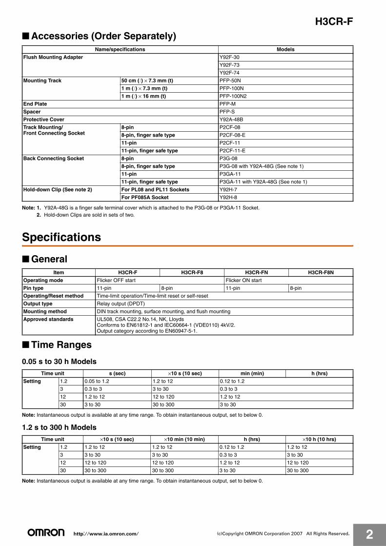
■ Time Ranges
0.05 s to 30 h Models
Note: Instantaneous output is available at any time range. To obtain instantaneous output, set to below 0.
1.2 s to 300 h Models
Note: Instantaneous output is available at any time range. To obtain instantaneous output, set to below 0.
Name/specifications Models
Flush Mounting Adapter Y92F-30
Y92F-73
Y92F-74
Mounting Track 50 cm (l) × 7.3 mm (t) PFP-50N
1 m (l) × 7.3 mm (t) PFP-100N
1 m (l) × 16 mm (t) PFP-100N2
End Plate PFP-M
Spacer PFP-S
Protective Cover Y92A-48B
Track Mounting/Front Connecting Socket
8-pin P2CF-08
8-pin, finger safe type P2CF-08-E
11-pin P2CF-11
11-pin, finger safe type P2CF-11-E
Back Connecting Socket 8-pin P3G-08
8-pin, finger safe type P3G-08 with Y92A-48G (See note 1)
11-pin P3GA-11
11-pin, finger safe type P3GA-11 with Y92A-48G (See note 1)
Hold-down Clip (See note 2) For PL08 and PL11 Sockets Y92H-7
For PF085A Socket Y92H-8
Item H3CR-F H3CR-F8 H3CR-FN H3CR-F8N
Operating mode Flicker OFF start Flicker ON start
Pin type 11-pin 8-pin 11-pin 8-pin
Operating/Reset method Time-limit operation/Time-limit reset or self-reset
Output type Relay output (DPDT)
Mounting method DIN track mounting, surface mounting, and flush mounting
Approved standards UL508, CSA C22.2 No.14, NK, LloydsConforms to EN61812-1 and IEC60664-1 (VDE0110) 4kV/2. Output category according to EN60947-5-1.
Time unit s (sec) ×10 s (10 sec) min (min) h (hrs)
Setting 1.2 0.05 to 1.2 1.2 to 12 0.12 to 1.2
3 0.3 to 3 3 to 30 0.3 to 3
12 1.2 to 12 12 to 120 1.2 to 12
30 3 to 30 30 to 300 3 to 30
Time unit ×10 s (10 sec) ×10 min (10 min) h (hrs) ×10 h (10 hrs)
Setting 1.2 1.2 to 12 1.2 to 12 0.12 to 1.2 1.2 to 12
3 3 to 30 3 to 30 0.3 to 3 3 to 30
12 12 to 120 12 to 120 1.2 to 12 12 to 120
30 30 to 300 30 to 300 3 to 30 30 to 300

http://www.ia.omron.com/ 3(c)Copyright OMRON Corporation 2007 All Rights Reserved.
H3CR-F■ Ratings
Note: 1. A power supply with a ripple of 20% max. (single-phase power supply with full-wave rectification) can be used with each DC Model.2. Do not use an inverter output as the power supply. Refer to Safety Precautions for All Timers for details.3. Refer to Safety Precautions for All Timers when using the Timer together with a 2-wire AC proximity sensor.
■ Characteristics
Note: Refer to the Life-test Curve.
Rated supply voltage (See notes 1, 2, and 3.) 100 to 240 VAC (50/60 Hz),12 VDC, 24 VAC/DC (50/60 Hz), 48 to 125 VDC
Operating voltage range 85% to 110% of rated supply voltage; 90% to 110% with 12-VDC models
Power reset Minimum power-opening time: 0.1 s
Power consumption 100 to 240 VAC: approx. 10 VA (2.1 W) at 240 VAC24 VAC/VDC: approx. 2 VA (1.7 W) at 24 VAC
approx. 1 W at 24 VDC48 to 125 VDC: approx. 1.5 W at 125 VDC12 VDC: approx. 1 W at 12 VDC
Control outputs Contact output: 5 A at 250 VAC/30 VDC, resistive load (cosφ = 1)
Accuracy of operating time
±0.2% FS max. (±0.2% FS ±10 ms max. in ranges of 1.2 and 3 s)
Setting error ±5% FS ±50 ms max.
Reset time 0.1 s max.
Reset voltage 10% max. of rated voltage
Influence of voltage ±0.2% FS max. (±0.2% FS ±10 ms max. in ranges of 1.2 and 3 s)
Influence of temperature ±1% FS max. (±1% FS ±10 ms max. in ranges of 1.2 and 3s)
Insulation resistance 100 MΩ min. (at 500 VDC)
Dielectric strength 2,000 VAC, 50/60 Hz for 1 min (between current-carrying metal parts and exposed non-current-carrying metal parts)2,000 VAC, 50/60 Hz for 1 min (between control output terminals and operating circuit)2,000 VAC, 50/60 Hz for 1 min (between contacts of different polarities)1,000 VAC, 50/60 Hz for 1 min (between contacts not located next to each other)
Impulse withstand voltage
3 kV (between power terminals) for 100 to 240 VAC, 48 to 125 VDC1 kV for 12 VDC, 24 VAC/DC4.5 kV (between current-carrying terminal and exposed non-current-carrying metal parts) for 100 to 240 VAC, 48 to 125 VDC1.5 kV for 12 VDC, 24 VAC/DC
Noise immunity ±1.5 kV (between power terminals), square-wave noise by noise simulator (pulse width: 100 ns/1 μs, 1-ns rise)±400 V for 12 VDC
Static immunity Malfunction: 8 kVDestruction: 15 kV
Vibration resistance Destruction: 10 to 55 Hz with 0.75-mm single amplitude for 2 hrs each in three directionsMalfunction: 10 to 55 Hz with 0.5-mm single amplitude for 10 min each in three directions
Shock resistance Destruction: 980 m/s2 three times each in six directionsMalfunction: 98 m/s2 three times each in six directions
Ambient temperature Operating: −10°C to 55°C (with no icing)Storage: −25°C to 65°C (with no icing)
Ambient humidity Operating: 35% to 85%
Life expectancy Mechanical: 20 million operations min. (under no load at 1,800 operations/h)Electrical: 100,000 operations min. (5 A at 250 VAC, resistive load at 1,800 operations/h) (See note)
EMC (EMI) EN61812-1Emission Enclosure: EN55011 Group 1 class AEmission AC Mains: EN55011 Group 1 class A(EMS) EN61812-1Immunity ESD: IEC61000-4-2: 6 kV contact discharge (level 3)
8 kV air discharge (level 3)Immunity RF-interference from AM Radio Waves: IEC61000-4-3: 10 V/m (80 MHz to 1 GHz) (level 3)Immunity RF-interference from Pulse-modulated Radio Waves: IEC61000-4-3: 10 V/m (900±5 MHz) (level 3)Immunity Conducted Disturbance: IEC61000-4-6: 10 V (0.15 to 80 MHz) (level 3)Immunity Burst: IEC61000-4-4: 2 kV power-line (level 3)
2 kV I/O signal-line (level 4)Immunity Surge: IEC61000-4-5: 1 kV line to line (level 3)
2 kV line to ground (level 3)
Case color Light Gray (Munsell 5Y7/1)
Degree of protection IP40 (panel surface)
Weight Approx. 100 g
http://www.ia.omron.com/ 4(c)Copyright OMRON Corporation 2007 All Rights Reserved.
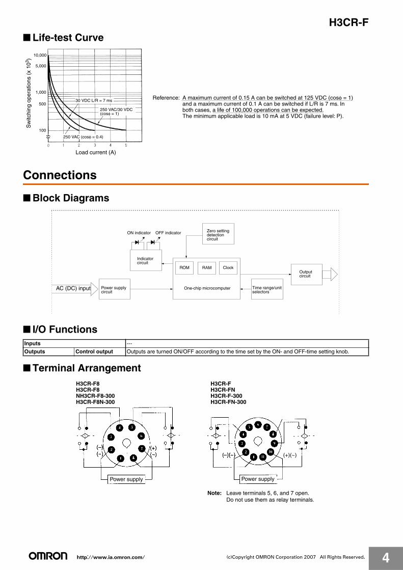
H3CR-F■ Life-test Curve
Connections
■ Block Diagrams
■ I/O Functions
■ Terminal Arrangement
10,000
5,000
1,000
500
100
Load current (A)
30 VDC L/R = 7 ms
250 VAC (cosφ = 0.4)
Sw
itchi
ng o
pera
tions
(x
103 )
250 VAC/30 VDC (cosφ = 1)
Reference: A maximum current of 0.15 A can be switched at 125 VDC (cosφ = 1) and a maximum current of 0.1 A can be switched if L/R is 7 ms. In both cases, a life of 100,000 operations can be expected.
The minimum applicable load is 10 mA at 5 VDC (failure level: P).
ON indicator OFF indicator
One-chip microcomputer
ROM RAM Clock
AC (DC) input Power supply circuit
Indicatorcircuit
Zero setting detectioncircuit
Time range/unit selectors
Outputcircuit
Inputs ---
Outputs Control output Outputs are turned ON/OFF according to the time set by the ON- and OFF-time setting knob.
(+)(~)
Power supply Power supply
H3CR-F8H3CR-F8NH3CR-F8-300H3CR-F8N-300
H3CR-FH3CR-FNH3CR-F-300H3CR-FN-300
Note: Leave terminals 5, 6, and 7 open.Do not use them as relay terminals.
http://www.ia.omron.com/ 5(c)Copyright OMRON Corporation 2007 All Rights Reserved.
H3CR-F
Operation
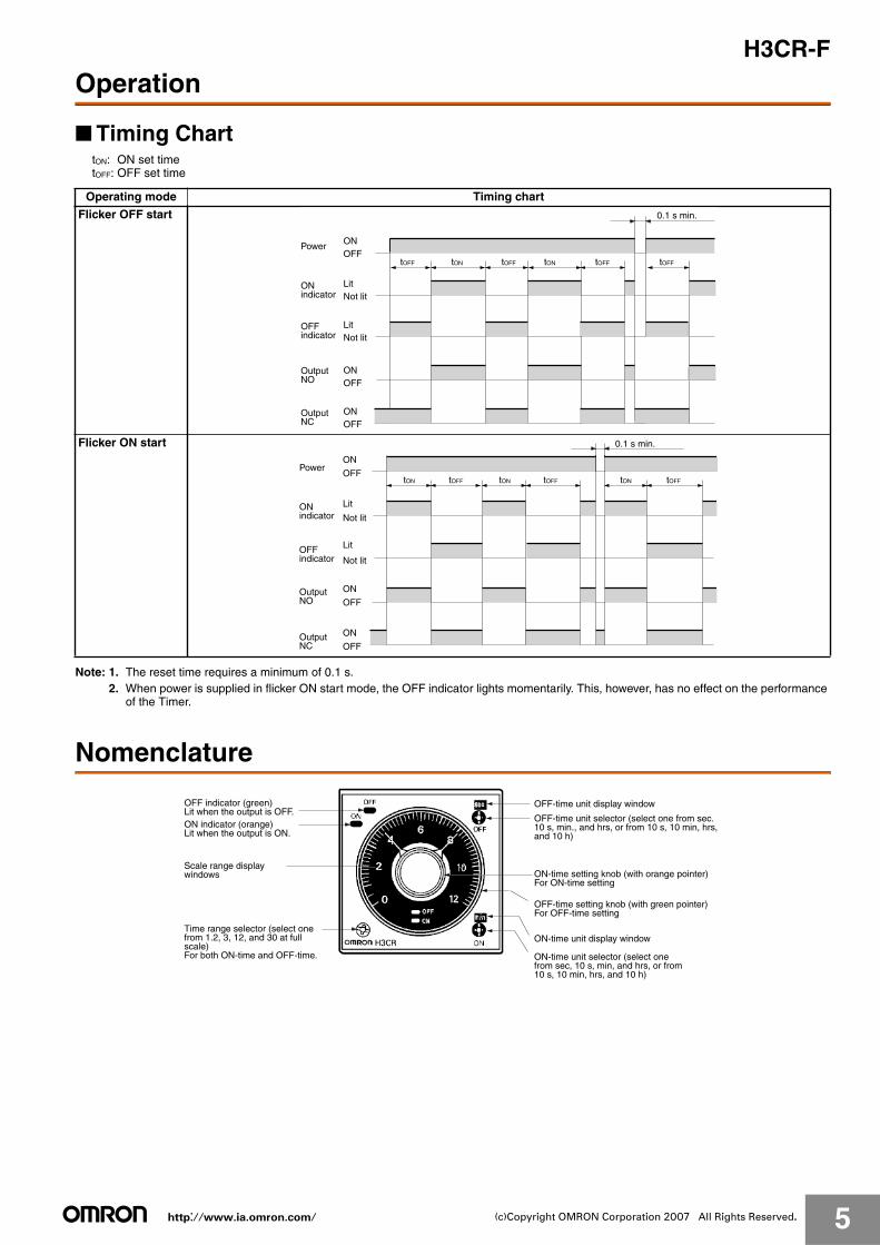
■ Timing CharttON: ON set timetOFF: OFF set time
Note: 1. The reset time requires a minimum of 0.1 s.2. When power is supplied in flicker ON start mode, the OFF indicator lights momentarily. This, however, has no effect on the performance
of the Timer.
Nomenclature
Operating mode Timing chart
Flicker OFF start
Flicker ON start
tOFF tON tOFF tON tOFF tOFF
ONOFF
Power
0.1 s min.
LitNot lit
LitNot lit
ONOFF
ONOFF
ONindicator
OFFindicator
OutputNO
OutputNC
tON tOFF tON tOFF tON tOFF
PowerON
OFF
0.1 s min.
Lit
Not lit
Lit
Not lit
ON
OFF
ON
OFF
ONindicator
OFFindicator
OutputNO
OutputNC
OFF-time unit display window
ON-time unit display window
OFF indicator (green)Lit when the output is OFF.ON indicator (orange)Lit when the output is ON.
Scale range display windows
Time range selector (select one from 1.2, 3, 12, and 30 at full scale)For both ON-time and OFF-time.
OFF-time unit selector (select one from sec. 10 s, min., and hrs, or from 10 s, 10 min, hrs, and 10 h)
ON-time setting knob (with orange pointer)For ON-time setting
OFF-time setting knob (with green pointer)For OFF-time setting
ON-time unit selector (select one from sec, 10 s, min, and hrs, or from 10 s, 10 min, hrs, and 10 h)
http://www.ia.omron.com/ 6(c)Copyright OMRON Corporation 2007 All Rights Reserved.
H3CR-F
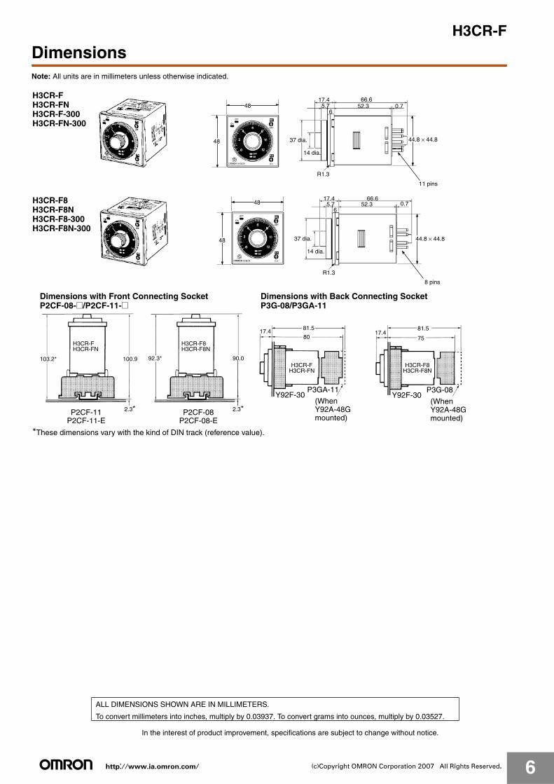
DimensionsNote: All units are in millimeters unless otherwise indicated.
66.60.7
17.452.3
65.7
R1.3
44.8 × 44.8
48
48
66.60.7
17.452.3
65.7
R1.3
44.8 × 44.8
48
48
37 dia.
14 dia.
37 dia.
14 dia.
11 pins
8 pins
H3CR-FH3CR-FNH3CR-F-300H3CR-FN-300
H3CR-F8H3CR-F8NH3CR-F8-300H3CR-F8N-300
103.2* 100.9
2.3*
92.3* 90.0
2.3*
8017.4 17.4
75
81.5 81.5
*These dimensions vary with the kind of DIN track (reference value).
Y92F-30P3GA-11
Y92F-30P3G-08
Dimensions with Front Connecting Socket P2CF-08-@/P2CF-11-@
H3CR-FH3CR-FN
P2CF-11P2CF-11-E
H3CR-F8H3CR-F8N
P2CF-08P2CF-08-E
Dimensions with Back Connecting Socket P3G-08/P3GA-11
H3CR-FH3CR-FN
H3CR-F8H3CR-F8N
(WhenY92A-48Gmounted)
(WhenY92A-48Gmounted)
In the interest of product improvement, specifications are subject to change without notice.
ALL DIMENSIONS SHOWN ARE IN MILLIMETERS.
To convert millimeters into inches, multiply by 0.03937. To convert grams into ounces, multiply by 0.03527.
http://www.ia.omron.com/ 7(c)Copyright OMRON Corporation 2007 All Rights Reserved.
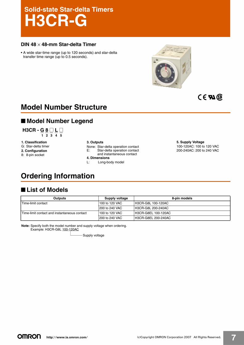
Solid-state Star-delta Timers
H3CR-GDIN 48 × 48-mm Star-delta Timer
• A wide star-time range (up to 120 seconds) and star-delta transfer time range (up to 0.5 seconds).
Model Number Structure
■ Model Number Legend
Ordering Information
■ List of Models
H3CR - G 8 @ L @1 2 3 4 5
1. ClassificationG: Star-delta timer2. Configuration8: 8-pin socket
3. Outputs
4. DimensionsL: Long-body model
5. Supply Voltage100-120AC: 100 to 120 VAC200-240AC: 200 to 240 VAC
None: Star-delta operation contactE: Star-delta operation contact and instantaneous contact
Outputs Supply voltage 8-pin models
Time-limit contact 100 to 120 VAC H3CR-G8L 100-120AC
200 to 240 VAC H3CR-G8L 200-240AC
Time-limit contact and instantaneous contact 100 to 120 VAC H3CR-G8EL 100-120AC
200 to 240 VAC H3CR-G8EL 200-240AC
Note: Specify both the model number and supply voltage when ordering.Example: H3CR-G8L 100-120AC
Supply voltage
http://www.ia.omron.com/ 8(c)Copyright OMRON Corporation 2007 All Rights Reserved.
H3CR-G
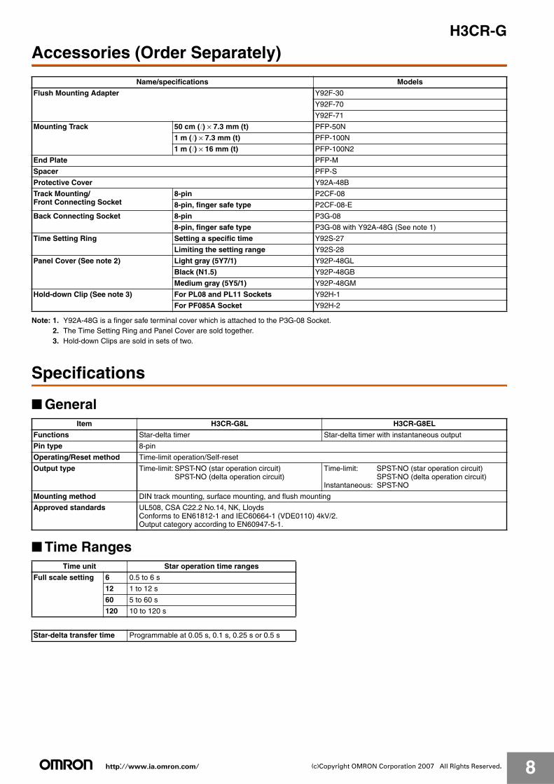
Accessories (Order Separately)
Note: 1. Y92A-48G is a finger safe terminal cover which is attached to the P3G-08 Socket.2. The Time Setting Ring and Panel Cover are sold together.3. Hold-down Clips are sold in sets of two.
Specifications
■ General
■ Time Ranges
Name/specifications Models
Flush Mounting Adapter Y92F-30
Y92F-70
Y92F-71
Mounting Track 50 cm (l) × 7.3 mm (t) PFP-50N
1 m (l) × 7.3 mm (t) PFP-100N
1 m (l) × 16 mm (t) PFP-100N2
End Plate PFP-M
Spacer PFP-S
Protective Cover Y92A-48B
Track Mounting/Front Connecting Socket
8-pin P2CF-08
8-pin, finger safe type P2CF-08-E
Back Connecting Socket 8-pin P3G-08
8-pin, finger safe type P3G-08 with Y92A-48G (See note 1)
Time Setting Ring Setting a specific time Y92S-27
Limiting the setting range Y92S-28
Panel Cover (See note 2) Light gray (5Y7/1) Y92P-48GL
Black (N1.5) Y92P-48GB
Medium gray (5Y5/1) Y92P-48GM
Hold-down Clip (See note 3) For PL08 and PL11 Sockets Y92H-1
For PF085A Socket Y92H-2
Item H3CR-G8L H3CR-G8EL
Functions Star-delta timer Star-delta timer with instantaneous output
Pin type 8-pin
Operating/Reset method Time-limit operation/Self-reset
Output type Time-limit: SPST-NO (star operation circuit)SPST-NO (delta operation circuit)
Time-limit: SPST-NO (star operation circuit)SPST-NO (delta operation circuit)
Instantaneous: SPST-NO
Mounting method DIN track mounting, surface mounting, and flush mounting
Approved standards UL508, CSA C22.2 No.14, NK, LloydsConforms to EN61812-1 and IEC60664-1 (VDE0110) 4kV/2. Output category according to EN60947-5-1.
Time unit Star operation time ranges
Full scale setting 6 0.5 to 6 s
12 1 to 12 s
60 5 to 60 s
120 10 to 120 s
Star-delta transfer time Programmable at 0.05 s, 0.1 s, 0.25 s or 0.5 s
http://www.ia.omron.com/ 9(c)Copyright OMRON Corporation 2007 All Rights Reserved.
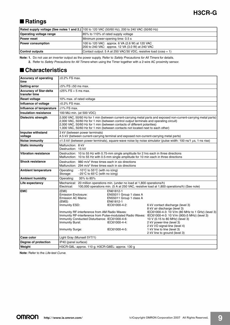
H3CR-G■ Ratings
Note: 1. Do not use an inverter output as the power supply. Refer to Safety Precautions for All Timers for details.2. Refer to Safety Precautions for All Timers when using the Timer together with a 2-wire AC proximity sensor.
■ Characteristics
Note: Refer to the Life-test Curve.
Rated supply voltage (See notes 1 and 2.) 100 to 120 VAC (50/60 Hz), 200 to 240 VAC (50/60 Hz)
Operating voltage range 85% to 110% of rated supply voltage
Power reset Minimum power-opening time: 0.5 s
Power consumption 100 to 120 VAC: approx. 6 VA (2.6 W) at 120 VAC200 to 240 VAC: approx. 12 VA (3.0 W) at 240 VAC
Control outputs Contact output: 5 A at 250 VAC/30 VDC, resistive load (cosφ = 1)
Accuracy of operating time
±0.2% FS max.
Setting error ±5% FS ±50 ms max.
Accuracy of Star-delta transfer time
±25% FS + 5 ms max.
Reset voltage 10% max. of rated voltage
Influence of voltage ±0.2% FS max.
Influence of temperature ±1% FS max.
Insulation resistance 100 MΩ min. (at 500 VDC)
Dielectric strength 2,000 VAC, 50/60 Hz for 1 min (between current-carrying metal parts and exposed non-current-carrying metal parts)2,000 VAC, 50/60 Hz for 1 min (between control output terminals and operating circuit)2,000 VAC, 50/60 Hz for 1 min (between contacts of different polarities)1,000 VAC, 50/60 Hz for 1 min (between contacts not located next to each other)
Impulse withstand voltage
3 kV (between power terminals)4.5 kV (between current-carrying terminal and exposed non-current-carrying metal parts)
Noise immunity ±1.5 kV (between power terminals), square-wave noise by noise simulator (pulse width: 100 ns/1 μs, 1-ns rise)
Static immunity Malfunction: 8 kVDestruction: 15 kV
Vibration resistance Destruction: 10 to 55 Hz with 0.75-mm single amplitude for 2 hrs each in three directionsMalfunction: 10 to 55 Hz with 0.5-mm single amplitude for 10 min each in three directions
Shock resistance Destruction: 980 m/s2 three times each in six directionsMalfunction: 294 m/s2 three times each in six directions
Ambient temperature Operating: −10°C to 55°C (with no icing)Storage: −25°C to 65°C (with no icing)
Ambient humidity Operating: 35% to 85%
Life expectancy Mechanical: 20 million operations min. (under no load at 1,800 operations/h)Electrical: 100,000 operations min. (5 A at 250 VAC, resistive load at 1,800 operations/h) (See note)
EMC (EMI) EN61812-1Emission Enclosure: EN55011 Group 1 class AEmission AC Mains: EN55011 Group 1 class A(EMS) EN61812-1Immunity ESD: IEC61000-4-2: 6 kV contact discharge (level 3)
8 kV air discharge (level 3)Immunity RF-interference from AM Radio Waves: IEC61000-4-3: 10 V/m (80 MHz to 1 GHz) (level 3)Immunity RF-interference from Pulse-modulated Radio Waves: IEC61000-4-3: 10 V/m (900±5 MHz) (level 3)Immunity Conducted Disturbance: IEC61000-4-6: 10 V (0.15 to 80 MHz) (level 3)Immunity Burst: IEC61000-4-4: 2 kV power-line (level 3)
2 kV I/O signal-line (level 4)Immunity Surge: IEC61000-4-5: 1 kV line to line (level 3)
2 kV line to ground (level 3)
Case color Light Gray (Munsell 5Y7/1)
Degree of protection IP40 (panel surface)
Weight H3CR-G8L: approx. 110 g; H3CR-G8EL: approx. 130 g
http://www.ia.omron.com/ 10(c)Copyright OMRON Corporation 2007 All Rights Reserved.
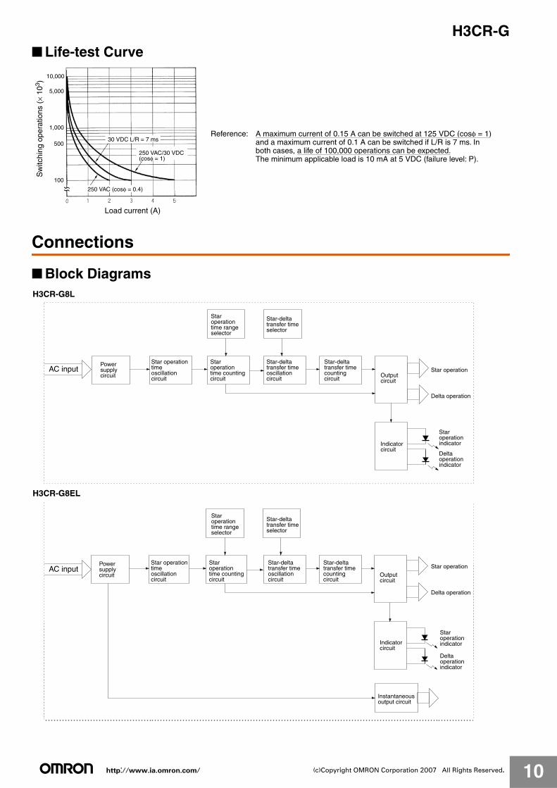
H3CR-G■ Life-test Curve
Connections
■ Block Diagrams
10,000
5,000
1,000
500
100
Load current (A)
30 VDC L/R = 7 ms
250 VAC (cosφ = 0.4)
Sw
itchi
ng o
pera
tions
(×
103 )
250 VAC/30 VDC (cosφ = 1)
Reference: A maximum current of 0.15 A can be switched at 125 VDC (cosφ = 1) and a maximum current of 0.1 A can be switched if L/R is 7 ms. In both cases, a life of 100,000 operations can be expected.
The minimum applicable load is 10 mA at 5 VDC (failure level: P).
H3CR-G8L
AC input Star operation
Delta operation
Power supplycircuit
Star operation timeoscillationcircuit
Staroperation time counting circuit
Staroperation time range selector
Star-deltatransfer time selector
Star-deltatransfer time oscillationcircuit
Star-deltatransfer time countingcircuit
Outputcircuit
Indicatorcircuit
Staroperation indicator
Deltaoperation indicator
H3CR-G8EL
Star operation
Delta operation
AC inputPower supplycircuit
Star operation timeoscillationcircuit
Staroperation time range selector
Staroperation time counting circuit
Star-deltatransfer time selector
Star-deltatransfer time oscillationcircuit
Star-deltatransfer time countingcircuit
Outputcircuit
Indicatorcircuit
Instantaneousoutput circuit
Staroperation indicator
Deltaoperation indicator
http://www.ia.omron.com/ 11(c)Copyright OMRON Corporation 2007 All Rights Reserved.
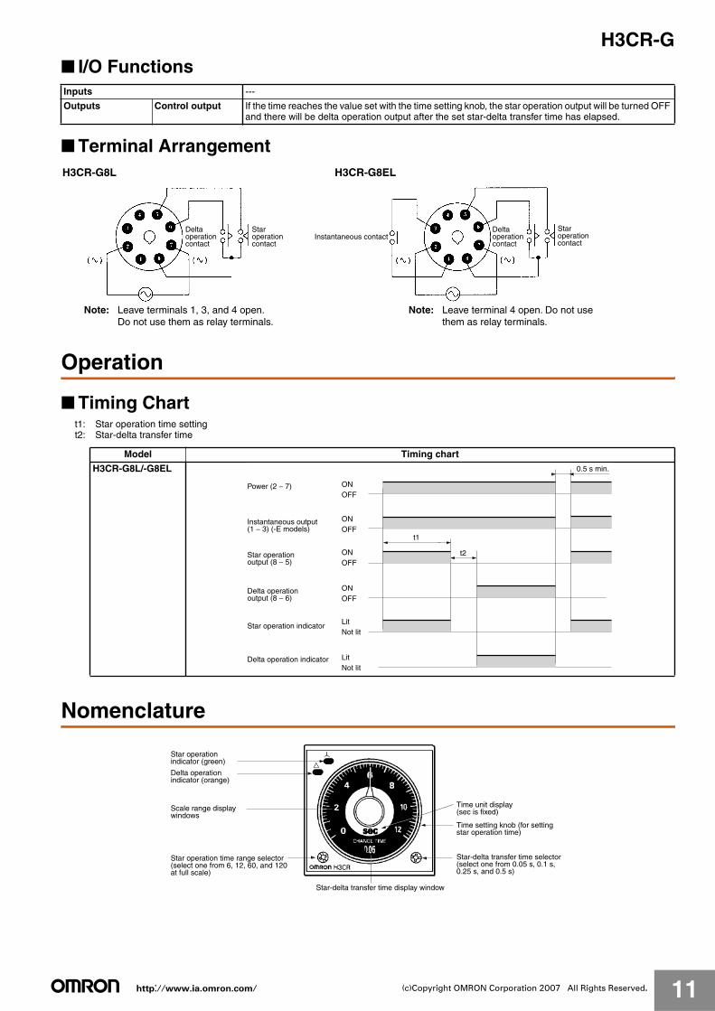
H3CR-G■ I/O Functions
■ Terminal Arrangement
Operation
■ Timing Chartt1: Star operation time settingt2: Star-delta transfer time
Nomenclature
Inputs ---
Outputs Control output If the time reaches the value set with the time setting knob, the star operation output will be turned OFF and there will be delta operation output after the set star-delta transfer time has elapsed.
H3CR-G8L H3CR-G8EL
Instantaneous contactDeltaoperation contact
Staroperation contact
Note: Leave terminals 1, 3, and 4 open. Do not use them as relay terminals.
Deltaoperation contact
Staroperation contact
Note: Leave terminal 4 open. Do not usethem as relay terminals.
Model Timing chart
H3CR-G8L/-G8EL
t1
t2
0.5 s min.
Power (2 − 7)
Star operation indicator
Delta operation indicator
ONOFF
LitNot lit
ONOFF
ONOFF
ONOFF
LitNot lit
Instantaneous output (1 − 3) (-E models)
Star operation output (8 − 5)
Delta operation output (8 − 6)
Star-delta transfer time display window
Star operation indicator (green)
Delta operation indicator (orange)
Scale range display windows
Star operation time range selector (select one from 6, 12, 60, and 120 at full scale)
Time unit display (sec is fixed)
Time setting knob (for setting star operation time)
Star-delta transfer time selector (select one from 0.05 s, 0.1 s, 0.25 s, and 0.5 s)
http://www.ia.omron.com/ 12(c)Copyright OMRON Corporation 2007 All Rights Reserved.
H3CR-G
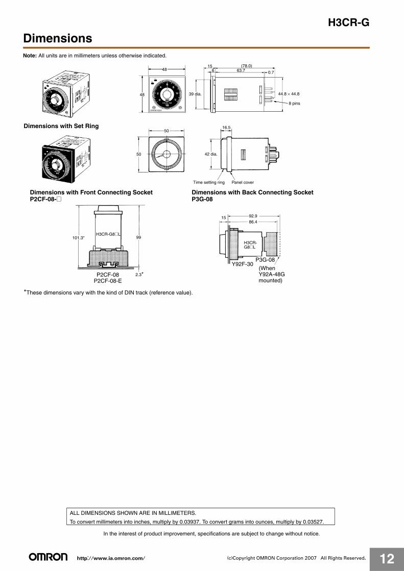
DimensionsNote: All units are in millimeters unless otherwise indicated.
156
(78.0)63.7
44.8 × 44.8
0.7
48
48
39 dia.
8 pins
5016.5
50
Dimensions with Set Ring
Time setting ring Panel cover
42 dia.
101.3* 99
2.3*
1586.492.9
Y92F-30P3G-08
H3CR-G8@L
*These dimensions vary with the kind of DIN track (reference value).
Dimensions with Front Connecting Socket P2CF-08-@
P2CF-08P2CF-08-E
Dimensions with Back Connecting Socket P3G-08
H3CR-G8@L
(WhenY92A-48Gmounted)
In the interest of product improvement, specifications are subject to change without notice.
ALL DIMENSIONS SHOWN ARE IN MILLIMETERS.
To convert millimeters into inches, multiply by 0.03937. To convert grams into ounces, multiply by 0.03527.
http://www.ia.omron.com/ 13(c)Copyright OMRON Corporation 2007 All Rights Reserved.
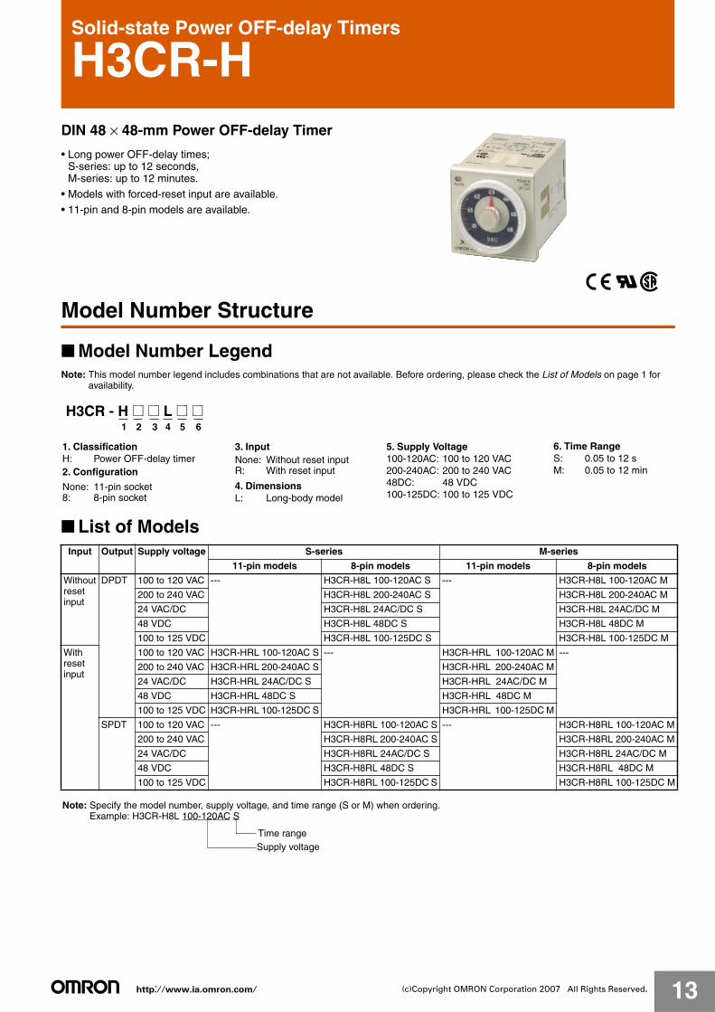
Solid-state Power OFF-delay Timers
H3CR-HDIN 48 × 48-mm Power OFF-delay Timer
• Long power OFF-delay times;S-series: up to 12 seconds,M-series: up to 12 minutes.
• Models with forced-reset input are available.• 11-pin and 8-pin models are available.
Model Number Structure
■ Model Number LegendNote: This model number legend includes combinations that are not available. Before ordering, please check the List of Models on page 1 for
availability.
■ List of Models
H3CR - H @ @ L @ @1 2 3 4 5 6
1. ClassificationH: Power OFF-delay timer2. Configuration
3. Input
4. DimensionsL: Long-body model
None: 11-pin socket8: 8-pin socket
None: Without reset inputR: With reset input
5. Supply Voltage 6. Time RangeS: 0.05 to 12 sM: 0.05 to 12 min
100-120AC: 100 to 120 VAC200-240AC: 200 to 240 VAC48DC: 48 VDC100-125DC: 100 to 125 VDC
Input Output Supply voltage S-series M-series
11-pin models 8-pin models 11-pin models 8-pin models
Withoutresetinput
DPDT 100 to 120 VAC --- H3CR-H8L 100-120AC S --- H3CR-H8L 100-120AC M
200 to 240 VAC H3CR-H8L 200-240AC S H3CR-H8L 200-240AC M
24 VAC/DC H3CR-H8L 24AC/DC S H3CR-H8L 24AC/DC M
48 VDC H3CR-H8L 48DC S H3CR-H8L 48DC M
100 to 125 VDC H3CR-H8L 100-125DC S H3CR-H8L 100-125DC M
With reset input
100 to 120 VAC H3CR-HRL 100-120AC S --- H3CR-HRL 100-120AC M ---
200 to 240 VAC H3CR-HRL 200-240AC S H3CR-HRL 200-240AC M
24 VAC/DC H3CR-HRL 24AC/DC S H3CR-HRL 24AC/DC M
48 VDC H3CR-HRL 48DC S H3CR-HRL 48DC M
100 to 125 VDC H3CR-HRL 100-125DC S H3CR-HRL 100-125DC M
SPDT 100 to 120 VAC --- H3CR-H8RL 100-120AC S --- H3CR-H8RL 100-120AC M
200 to 240 VAC H3CR-H8RL 200-240AC S H3CR-H8RL 200-240AC M
24 VAC/DC H3CR-H8RL 24AC/DC S H3CR-H8RL 24AC/DC M
48 VDC H3CR-H8RL 48DC S H3CR-H8RL 48DC M
100 to 125 VDC H3CR-H8RL 100-125DC S H3CR-H8RL 100-125DC M
Note: Specify the model number, supply voltage, and time range (S or M) when ordering.Example: H3CR-H8L 100-120AC S
Supply voltageTime range
http://www.ia.omron.com/ 14(c)Copyright OMRON Corporation 2007 All Rights Reserved.
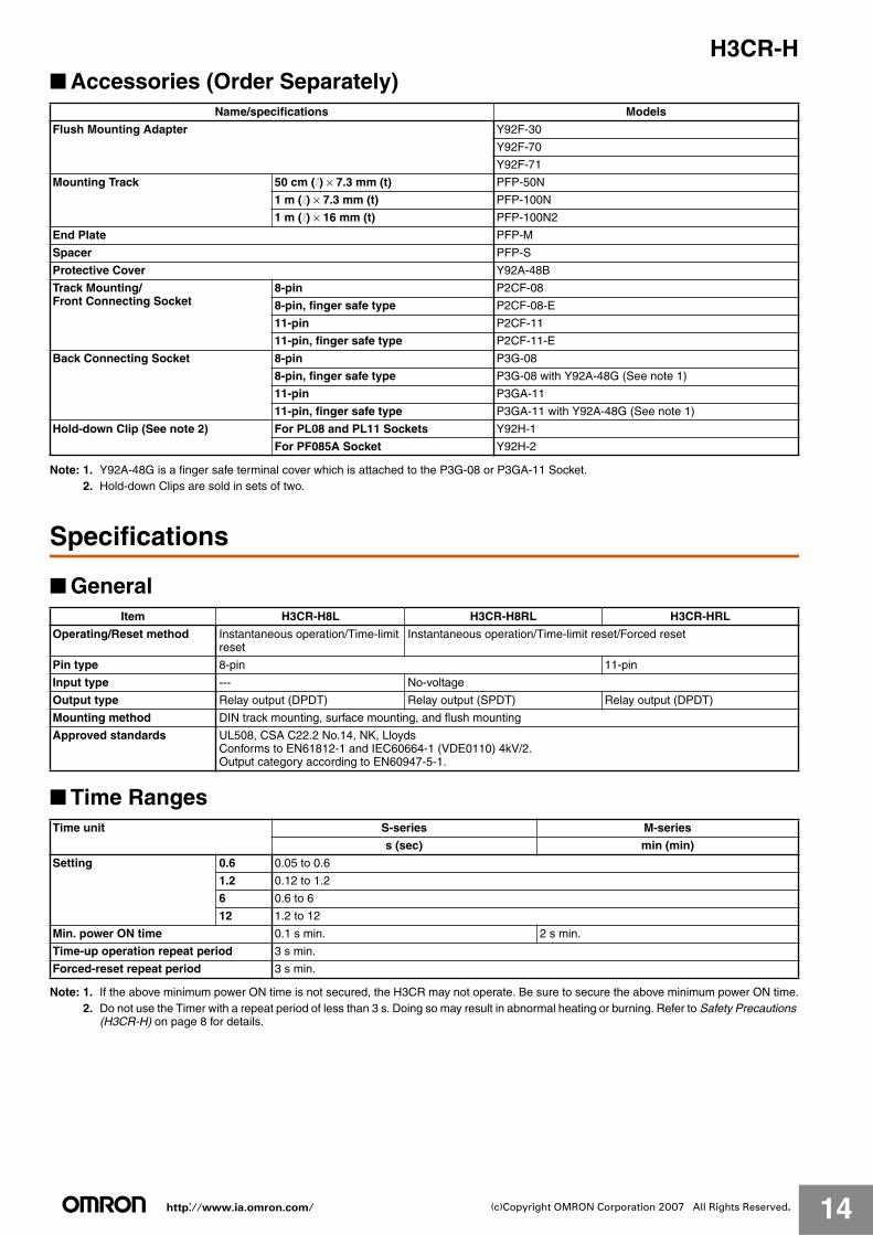
H3CR-H■ Accessories (Order Separately)
Note: 1. Y92A-48G is a finger safe terminal cover which is attached to the P3G-08 or P3GA-11 Socket.2. Hold-down Clips are sold in sets of two.
Specifications
■ General
■ Time Ranges
Note: 1. If the above minimum power ON time is not secured, the H3CR may not operate. Be sure to secure the above minimum power ON time.2. Do not use the Timer with a repeat period of less than 3 s. Doing so may result in abnormal heating or burning. Refer to Safety Precautions
(H3CR-H) on page 8 for details.
Name/specifications Models
Flush Mounting Adapter Y92F-30
Y92F-70
Y92F-71
Mounting Track 50 cm (l) × 7.3 mm (t) PFP-50N
1 m (l) × 7.3 mm (t) PFP-100N
1 m (l) × 16 mm (t) PFP-100N2
End Plate PFP-M
Spacer PFP-S
Protective Cover Y92A-48B
Track Mounting/Front Connecting Socket
8-pin P2CF-08
8-pin, finger safe type P2CF-08-E
11-pin P2CF-11
11-pin, finger safe type P2CF-11-E
Back Connecting Socket 8-pin P3G-08
8-pin, finger safe type P3G-08 with Y92A-48G (See note 1)
11-pin P3GA-11
11-pin, finger safe type P3GA-11 with Y92A-48G (See note 1)
Hold-down Clip (See note 2) For PL08 and PL11 Sockets Y92H-1
For PF085A Socket Y92H-2
Item H3CR-H8L H3CR-H8RL H3CR-HRL
Operating/Reset method Instantaneous operation/Time-limit reset
Instantaneous operation/Time-limit reset/Forced reset
Pin type 8-pin 11-pin
Input type --- No-voltage
Output type Relay output (DPDT) Relay output (SPDT) Relay output (DPDT)
Mounting method DIN track mounting, surface mounting, and flush mounting
Approved standards UL508, CSA C22.2 No.14, NK, LloydsConforms to EN61812-1 and IEC60664-1 (VDE0110) 4kV/2. Output category according to EN60947-5-1.
Time unit S-series M-series
s (sec) min (min)
Setting 0.6 0.05 to 0.6
1.2 0.12 to 1.2
6 0.6 to 6
12 1.2 to 12
Min. power ON time 0.1 s min. 2 s min.
Time-up operation repeat period 3 s min.
Forced-reset repeat period 3 s min.
http://www.ia.omron.com/ 15(c)Copyright OMRON Corporation 2007 All Rights Reserved.
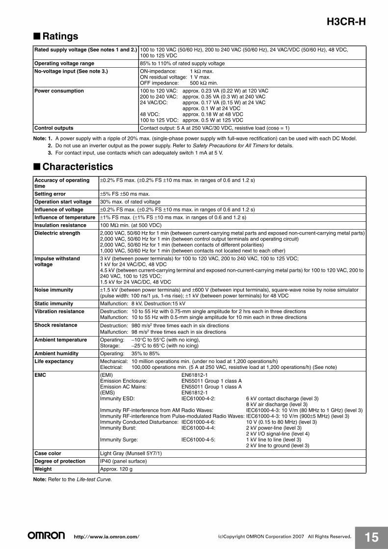
H3CR-H■ Ratings
Note: 1. A power supply with a ripple of 20% max. (single-phase power supply with full-wave rectification) can be used with each DC Model.2. Do not use an inverter output as the power supply. Refer to Safety Precautions for All Timers for details.3. For contact input, use contacts which can adequately switch 1 mA at 5 V.
■ Characteristics
Note: Refer to the Life-test Curve.
Rated supply voltage (See notes 1 and 2.) 100 to 120 VAC (50/60 Hz), 200 to 240 VAC (50/60 Hz), 24 VAC/VDC (50/60 Hz), 48 VDC, 100 to 125 VDC
Operating voltage range 85% to 110% of rated supply voltage
No-voltage input (See note 3.) ON-impedance: 1 kΩ max.ON residual voltage: 1 V max.OFF impedance: 500 kΩ min.
Power consumption 100 to 120 VAC: approx. 0.23 VA (0.22 W) at 120 VAC200 to 240 VAC: approx. 0.35 VA (0.3 W) at 240 VAC24 VAC/DC: approx. 0.17 VA (0.15 W) at 24 VAC
approx. 0.1 W at 24 VDC48 VDC: approx. 0.18 W at 48 VDC100 to 125 VDC: approx. 0.5 W at 125 VDC
Control outputs Contact output: 5 A at 250 VAC/30 VDC, resistive load (cosφ = 1)
Accuracy of operating time
±0.2% FS max. (±0.2% FS ±10 ms max. in ranges of 0.6 and 1.2 s)
Setting error ±5% FS ±50 ms max.
Operation start voltage 30% max. of rated voltage
Influence of voltage ±0.2% FS max. (±0.2% FS ±10 ms max. in ranges of 0.6 and 1.2 s)
Influence of temperature ±1% FS max. (±1% FS ±10 ms max. in ranges of 0.6 and 1.2 s)
Insulation resistance 100 MΩ min. (at 500 VDC)
Dielectric strength 2,000 VAC, 50/60 Hz for 1 min (between current-carrying metal parts and exposed non-current-carrying metal parts)2,000 VAC, 50/60 Hz for 1 min (between control output terminals and operating circuit)2,000 VAC, 50/60 Hz for 1 min (between contacts of different polarities)1,000 VAC, 50/60 Hz for 1 min (between contacts not located next to each other)
Impulse withstand voltage
3 kV (between power terminals) for 100 to 120 VAC, 200 to 240 VAC, 100 to 125 VDC;1 kV for 24 VAC/DC, 48 VDC4.5 kV (between current-carrying terminal and exposed non-current-carrying metal parts) for 100 to 120 VAC, 200 to 240 VAC, 100 to 125 VDC;1.5 kV for 24 VAC/DC, 48 VDC
Noise immunity ±1.5 kV (between power terminals) and ±600 V (between input terminals), square-wave noise by noise simulator (pulse width: 100 ns/1 μs, 1-ns rise); ±1 kV (between power terminals) for 48 VDC
Static immunity Malfunction: 8 kV, Destruction:15 kV
Vibration resistance Destruction: 10 to 55 Hz with 0.75-mm single amplitude for 2 hrs each in three directionsMalfunction: 10 to 55 Hz with 0.5-mm single amplitude for 10 min each in three directions
Shock resistance Destruction: 980 m/s2 three times each in six directionsMalfunction: 98 m/s2 three times each in six directions
Ambient temperature Operating: −10°C to 55°C (with no icing), Storage: −25°C to 65°C (with no icing)
Ambient humidity Operating: 35% to 85%
Life expectancy Mechanical: 10 million operations min. (under no load at 1,200 operations/h)Electrical: 100,000 operations min. (5 A at 250 VAC, resistive load at 1,200 operations/h) (See note)
EMC (EMI) EN61812-1Emission Enclosure: EN55011 Group 1 class AEmission AC Mains: EN55011 Group 1 class A(EMS) EN61812-1Immunity ESD: IEC61000-4-2: 6 kV contact discharge (level 3)
8 kV air discharge (level 3)Immunity RF-interference from AM Radio Waves: IEC61000-4-3: 10 V/m (80 MHz to 1 GHz) (level 3)Immunity RF-interference from Pulse-modulated Radio Waves: IEC61000-4-3: 10 V/m (900±5 MHz) (level 3)Immunity Conducted Disturbance: IEC61000-4-6: 10 V (0.15 to 80 MHz) (level 3)Immunity Burst: IEC61000-4-4: 2 kV power-line (level 3)
2 kV I/O signal-line (level 4)Immunity Surge: IEC61000-4-5: 1 kV line to line (level 3)
2 kV line to ground (level 3)
Case color Light Gray (Munsell 5Y7/1)
Degree of protection IP40 (panel surface)
Weight Approx. 120 g
http://www.ia.omron.com/ 16(c)Copyright OMRON Corporation 2007 All Rights Reserved.
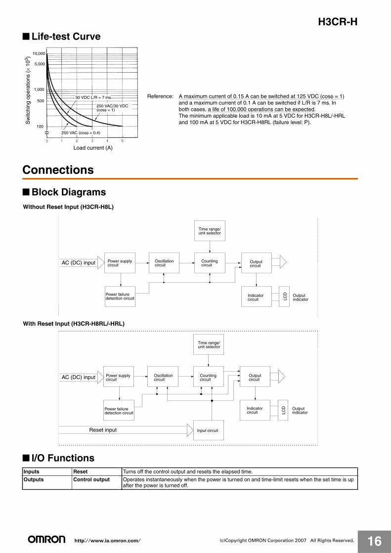
H3CR-H■ Life-test Curve
Connections
■ Block Diagrams
■ I/O Functions
10,000
5,000
1,000
500
100
Load current (A)
30 VDC L/R = 7 ms
250 VAC (cosφ = 0.4)
Sw
itchi
ng o
pera
tions
(×
103 )
250 VAC/30 VDC (cosφ = 1)
Reference: A maximum current of 0.15 A can be switched at 125 VDC (cosφ = 1) and a maximum current of 0.1 A can be switched if L/R is 7 ms. In both cases, a life of 100,000 operations can be expected.
The minimum applicable load is 10 mA at 5 VDC for H3CR-H8L/-HRL and 100 mA at 5 VDC for H3CR-H8RL (failure level: P).
Without Reset Input (H3CR-H8L)
LCD
AC (DC) input Power supply circuit
Power failure detection circuit
Oscillationcircuit
Time range/ unit selector
Countingcircuit
Outputcircuit
Indicatorcircuit
Outputindicator
With Reset Input (H3CR-H8RL/-HRL)
LCD
Input circuit
AC (DC) input
Reset input
Power supply circuit
Power failure detection circuit
Oscillationcircuit
Time range/ unit selector
Countingcircuit
Outputcircuit
Indicatorcircuit
Outputindicator
Inputs Reset Turns off the control output and resets the elapsed time.
Outputs Control output Operates instantaneously when the power is turned on and time-limit resets when the set time is up after the power is turned off.
http://www.ia.omron.com/ 17(c)Copyright OMRON Corporation 2007 All Rights Reserved.
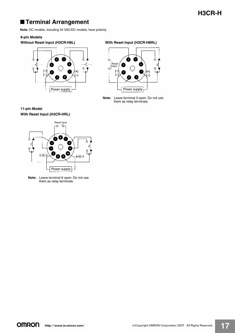
H3CR-H■ Terminal ArrangementNote: DC models, including 24 VAC/DC models, have polarity.
8-pin Models
Without Reset Input (H3CR-H8L) With Reset Input (H3CR-H8RL)
11-pin Model
With Reset Input (H3CR-HRL)
Power supply
Power supply
Reset input
Power supply
Resetinput
Note: Leave terminal 3 open. Do not usethem as relay terminals.
Note: Leave terminal 6 open. Do not usethem as relay terminals.
http://www.ia.omron.com/ 18(c)Copyright OMRON Corporation 2007 All Rights Reserved.
H3CR-H
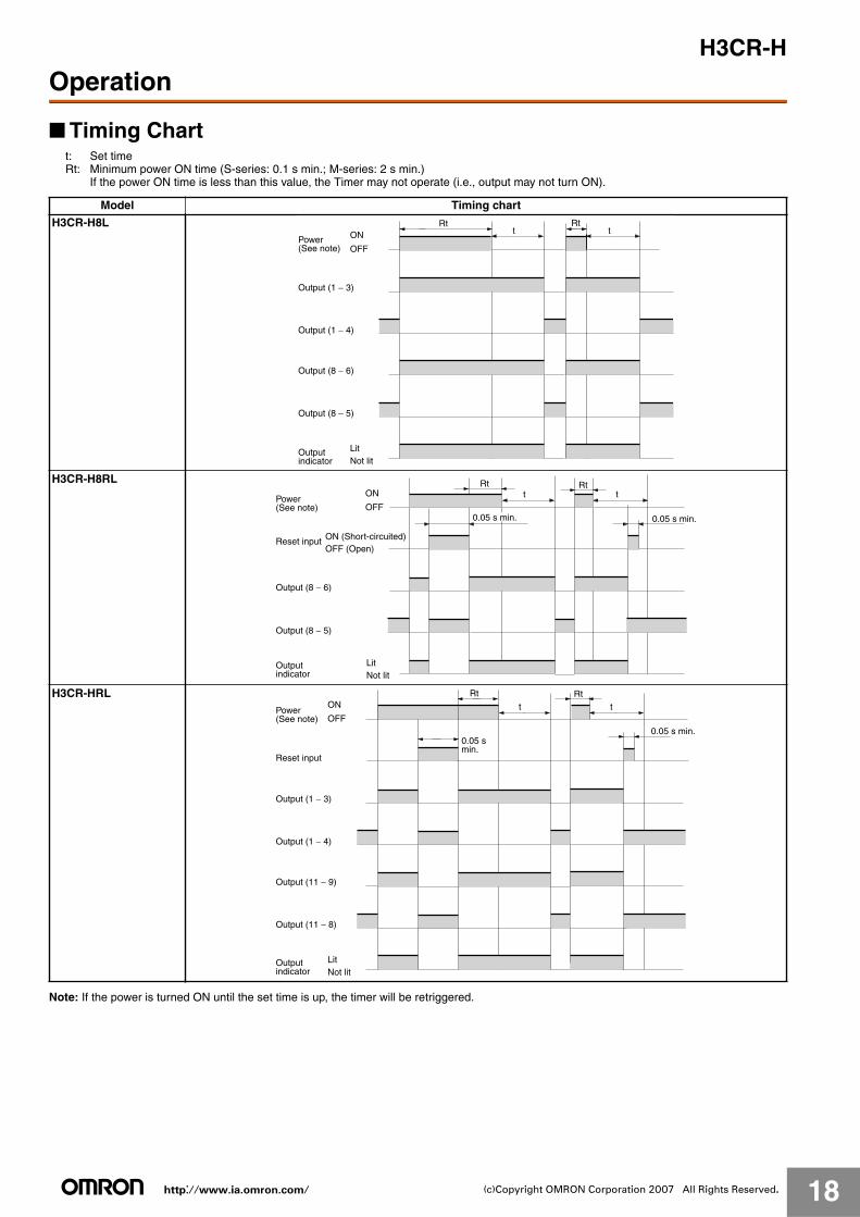
Operation
■ Timing Chartt: Set timeRt: Minimum power ON time (S-series: 0.1 s min.; M-series: 2 s min.)
If the power ON time is less than this value, the Timer may not operate (i.e., output may not turn ON).
Note: If the power is turned ON until the set time is up, the timer will be retriggered.
Model Timing chart
H3CR-H8L
H3CR-H8RL
H3CR-HRL
Rtt
RttON
OFF
Output (1 − 3)
LitNot lit
Output (1 − 4)
Output (8 − 6)
Output (8 − 5)
Power (See note)
Outputindicator
t tRtRt
LitNot lit
ON
OFF
Output (8 − 6)
Reset input ON (Short-circuited) OFF (Open)
0.05 s min. 0.05 s min.
Output (8 − 5)
Power (See note)
Outputindicator
Rt
tRt
tON
OFF
Output (1 − 3)
LitNot lit
Output (1 − 4)
Output (11 − 9)
Output (11 − 8)
Reset input
0.05 s min.
Power (See note)
Outputindicator
0.05 s min.
http://www.ia.omron.com/ 19(c)Copyright OMRON Corporation 2007 All Rights Reserved.
H3CR-H
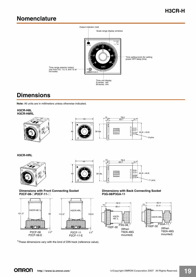
Nomenclature
DimensionsNote: All units are in millimeters unless otherwise indicated.
Output indicator (red)
Scale range display windows
Time range selector (select one from 0.6, 1.2, 6, and 12 at full scale)
Time unit displayS-series: secM-series: min
Time setting knob (for setting power OFF-delay time)
15 78.06 63.7 0.7
44.8 × 44.8
48
48
15 78.06 63.7 0.7
44.8 × 44.8
48
48
H3CR-HRL
39 dia.
39 dia.
8 pins
11 pins
H3CR-H8LH3CR-H8RL
112.2* 109.9
2.3*
15 91.4
101.3* 99
2.3*
1586.4
92.9 92.9
H3CR-HRL
*These dimensions vary with the kind of DIN track (reference value).
Y92F-30P3G-08
H3CR-H8@L
Y92F-30P3GA-11
H3CR-HRL
Dimensions with Front Connecting Socket P2CF-08-@/P2CF-11-@
P2CF-08P2CF-08-E
P2CF-11P2CF-11-E
H3CR-H8@L
(WhenY92A-48Gmounted)
(WhenY92A-48Gmounted)
Dimensions with Back Connecting Socket P3G-08/P3GA-11
http://www.ia.omron.com/ 20(c)Copyright OMRON Corporation 2007 All Rights Reserved.
H3CR-H
Safety Precautions (H3CR-H)Note: The undermentioned is common for all H3CR-H models.
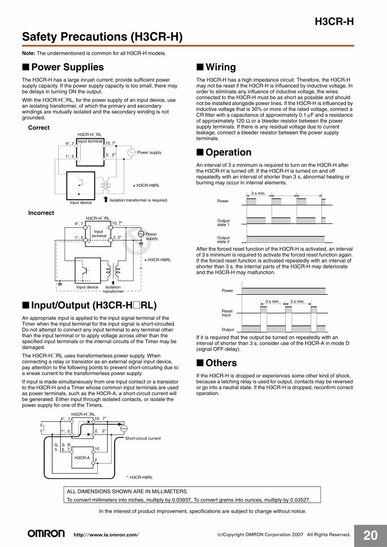
■ Power SuppliesThe H3CR-H has a large inrush current; provide sufficient power supply capacity. If the power supply capacity is too small, there may be delays in turning ON the output.
With the H3CR-H@RL, for the power supply of an input device, use an isolating transformer, of which the primary and secondary windings are mutually isolated and the secondary winding is not grounded.
■ Input/Output (H3CR-H@RL)An appropriate input is applied to the input signal terminal of the Timer when the input terminal for the input signal is short-circuited. Do not attempt to connect any input terminal to any terminal other than the input terminal or to apply voltage across other than the specified input terminals or the internal circuits of the Timer may be damaged.
The H3CR-H@RL uses transformerless power supply. When connecting a relay or transistor as an external signal input device, pay attention to the following points to prevent short-circuiting due to a sneak current to the transformerless power supply.
If input is made simultaneously from one input contact or a transistor to the H3CR-H and a Timer whose common input terminals are used as power terminals, such as the H3CR-A, a short-circuit current will be generated. Either input through isolated contacts, or isolate the power supply for one of the Timers.
■ WiringThe H3CR-H has a high impedance circuit. Therefore, the H3CR-H may not be reset if the H3CR-H is influenced by inductive voltage. In order to eliminate any influence of inductive voltage, the wires connected to the H3CR-H must be as short as possible and should not be installed alongside power lines. If the H3CR-H is influenced by inductive voltage that is 30% or more of the rated voltage, connect a CR filter with a capacitance of approximately 0.1 μF and a resistance of approximately 120 Ω or a bleeder resistor between the power supply terminals. If there is any residual voltage due to current leakage, connect a bleeder resistor between the power supply terminals.
■ OperationAn interval of 3 s minimum is required to turn on the H3CR-H after the H3CR-H is turned off. If the H3CR-H is turned on and off repeatedly with an interval of shorter than 3 s, abnormal heating or burning may occur in internal elements.
After the forced reset function of the H3CR-H is activated, an interval of 3 s minimum is required to activate the forced reset function again. If the forced reset function is activated repeatedly with an interval of shorter than 3 s, the internal parts of the H3CR-H may deteriorate and the H3CR-H may malfunction.
If it is required that the output be turned on repeatedly with an interval of shorter than 3 s, consider use of the H3CR-A in mode D (signal OFF-delay).
■ OthersIf the H3CR-H is dropped or experiences some other kind of shock, because a latching relay is used for output, contacts may be reversed or go into a neutral state. If the H3CR-H is dropped, reconfirm correct operation.
10,
2,
4*, 7
1*, 5
7*
2*
Correct
Input terminal
H3CR-H@RL
Power supply
Isolation transformer is required.Input device
*:H3CR-H8RL
H3CR-H@RL
Power supply
Inputterminal
Input device
4*, 7 10, 7*
2, 2*1*, 5
Incorrect
Isolationtransformer
*:H3CR-H8RL
10, 7*
2, 2*
10
2
R.S.76
G.5
4*,
51*,
7H3CR-H@RL
Short-circuit current
*: H3CR-H8RL
H3CR-A
Power
3 s min.
Outputstate 1
Outputstate 2
Power
3 s min.
Output
3 s min.
Resetinput
In the interest of product improvement, specifications are subject to change without notice.
ALL DIMENSIONS SHOWN ARE IN MILLIMETERS.
To convert millimeters into inches, multiply by 0.03937. To convert grams into ounces, multiply by 0.03527.
http://www.ia.omron.com/ C-1(c)Copyright OMRON Corporation 2007 All Rights Reserved.
Safety Precautions for All TimersRefer to the Safety Precautions for individual Timers for precautions specific to each Timer.
!WARNING
!CAUTION
■ Precautions for Safe Use
Operating Environment• Use the Timer within the ratings specified for ambient operating
temperature and ambient operating humidity for each model.• Store the Timer with the specified temperature range for each
model. If the Timer has been stored at a temperature of less than −10°C, allow the Timer to stand at room temperature for at least 3 hours before using it.
• Use the Timer within the performance specified for water and oil exposure for each model.
• Do not use the Timer in locations subject to shock and vibration. Long-term usage in such locations may damage the Timer due to stress. Magnetic contactors generate a shock of 1,000 to 2,000 m/s2 when switching a load. When mounting to DIN Track, separate magnetic contactors from the Timer so that the Timer is not subjected to vibration and shock. Use anti-vibration rubber.
• Do not use the Timer in locations subject to excessive dust, corrosive gases, or direct sunlight.
• Do not use organic solvents (such as paint thinner or benzine), strong alkalis, or strong acids because they will damage the external finish of the Timer.
• Separate the input devices, input wiring, and Timer as far as possible from sources of noise and power lines carrying noise.
• When using the Timer in environments subject to large amounts of static electricity (e.g., pipes carrying molding materials, powders, or fluid materials), separate the Timer as far as possible from the sources of static electricity.
• Do not remove the external case from the Timer. • Do not use the Timer in locations where condensation may occur
due to high humidity or sudden temperature changes. Condensation inside the Timer may result in malfunction or damage to Timer elements.
• The life of internal parts may be reduced if Timers are mounted in close proximity to each other.
• Resin and rubber parts (e.g., rubber packing) may deteriorate, shrink, or harden depending on the operating environment (e.g., subjected to corrosive gases, ultraviolet light, or high temperatures). We recommend periodic inspection and replacement.
• Normal operation may not be possible in locations subject to sulfidizing gas, such as in sewer systems or waste incinerators. OMRON does not market any Timers or other control devices for operation in atmospheres containing sulfidizing gas. Seal the Timer so that sulfidizing gas will not enter it. If sealing is not possible, OMRON does provide special Timers with improved resistance to sulfidizing gas. Ask your OMRON representative for details.
Power Supply• Be sure that the voltage applied is within the specified range,
otherwise the internal elements of the Timer may be damaged.• Install a switch or circuit breaker that allows the operator to
immediately turn OFF the power, and label it to clearly indicate its function.
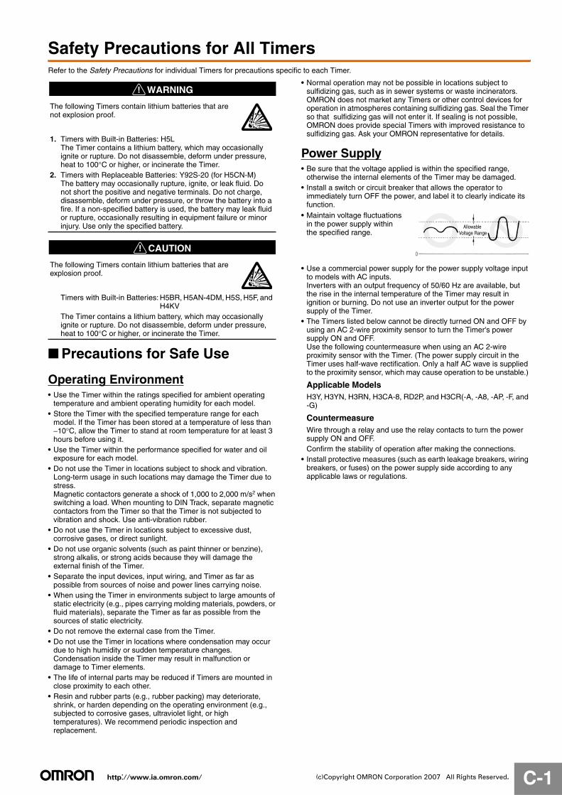
• Maintain voltage fluctuations in the power supply within the specified range.
• Use a commercial power supply for the power supply voltage input to models with AC inputs. Inverters with an output frequency of 50/60 Hz are available, but the rise in the internal temperature of the Timer may result in ignition or burning. Do not use an inverter output for the power supply of the Timer.
• The Timers listed below cannot be directly turned ON and OFF by using an AC 2-wire proximity sensor to turn the Timer's power supply ON and OFF. Use the following countermeasure when using an AC 2-wire proximity sensor with the Timer. (The power supply circuit in the Timer uses half-wave rectification. Only a half AC wave is supplied to the proximity sensor, which may cause operation to be unstable.)
Applicable ModelsH3Y, H3YN, H3RN, H3CA-8, RD2P, and H3CR(-A, -A8, -AP, -F, and -G)
CountermeasureWire through a relay and use the relay contacts to turn the power supply ON and OFF. Confirm the stability of operation after making the connections.
• Install protective measures (such as earth leakage breakers, wiring breakers, or fuses) on the power supply side according to any applicable laws or regulations.
The following Timers contain lithium batteries that are not explosion proof.
1. Timers with Built-in Batteries: H5LThe Timer contains a lithium battery, which may occasionally ignite or rupture. Do not disassemble, deform under pressure, heat to 100°C or higher, or incinerate the Timer.
2. Timers with Replaceable Batteries: Y92S-20 (for H5CN-M)The battery may occasionally rupture, ignite, or leak fluid. Do not short the positive and negative terminals. Do not charge, disassemble, deform under pressure, or throw the battery into a fire. If a non-specified battery is used, the battery may leak fluid or rupture, occasionally resulting in equipment failure or minor injury. Use only the specified battery.
The following Timers contain lithium batteries that are explosion proof.
Timers with Built-in Batteries: H5BR, H5AN-4DM, H5S, H5F, and H4KV
The Timer contains a lithium battery, which may occasionally ignite or rupture. Do not disassemble, deform under pressure, heat to 100°C or higher, or incinerate the Timer.
Allowable Voltage Range
http://www.ia.omron.com/ C-2(c)Copyright OMRON Corporation 2007 All Rights Reserved.
Correctly Handling Input SignalsMalfunction due to noise may occur if input wiring is placed in the same duct or conduit as power lines or high-voltage lines. Separate input wiring from power lines and wire them in a separate system. Also, use shielded cables, use metal conduits, and keep wiring distances as short as possible.
Timers with Relays• Do not connect a load that exceeds contact ratings, such as the
switching capacity (contact voltage or contact current). Insulation faults, contact welding, contact faults, and other failures to achieve specified performance may occur and the relay may be damaged or may burn.
• Continued use with deteriorated performance may ultimately result in insulation breakdown between circuits or relay burning. The life of the built-in relay is greatly affected by switching conditions. Before using the Timer, test operation under actual application conditions and confirm that the switching frequency presents no problems in performance.
• Electrical life depends on the type of load, switching frequency, and ambient environment. Observe the following precautions when using the Timer. When switching a DC load, contact transfer may cause the contacts to stick or may cause contact failure. Confirm applicability and consider using a surge absorbing element. When switching at high frequencies, heat generated by arcing may cause contacts to melt or may cause metal corrosion. Consider connecting an arc absorbing element, reducing the switching frequency, or lowering the humidity.
• The surge current depends on the type of load, which also affects contact switching frequency and the number of operations. Check the rated current and the surge current, and design the circuits with sufficient margin.
• Arcing when switching and relay heating may result in ignition or explosion. Do not use the Timer in atmospheres subject to inflammable or explosive gases.
• Contact faults may occur. Do not use the Timer in atmospheres subject to sulfidizing gas, chloride gas, or silicon gas.
• The switching capacity for DC voltage loads is lower than that for AC voltage loads.
Timers with Non-contact Outputs• Short faults or open faults may occur due to destruction of the
output element. Do not use the Timer for a load that exceeds the rated output current.
• Short faults or open faults may occur due to destruction of the output element from reverse electromotive force. When using the Timer for a DC inductive load, always connect a diode as a countermeasure against reverse electromotive force.
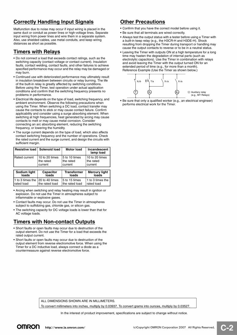
Other Precautions• Confirm that you have the correct model before using it. • Be sure that all terminals are wired correctly. • Always test the output status with a tester before using a Timer with
a built-in keep relay (e.g., the H3CR-H and H3DE-H). Shock resulting from dropping the Timer during transport or handling may cause the output contacts to reverse or to be in a neutral status.
• Leaving the Timer with outputs ON at a high temperature for a long time may hasten the degradation of internal parts (such as electrolytic capacitors). Use the Timer in combination with relays and avoid leaving the Timer with the output turned ON for an extended period of time (e.g., for more than a month).Reference Example (Use the Timer as shown below.)
• Be sure that only a qualified worker (e.g., an electrical engineer) performs electrical work for the Timer.
Resistive load Solenoid load Motor load Incandescent lamp load
Rated current 10 to 20 times the rated current
5 to 10 times the rated current
10 to 20 times the rated current
Sodium light loads
Capacitor loads
Transformer loads
Mercury light loads
1 to 3 times the rated load
20 to 40 times the rated load
5 to 15 times the rated load
1 to 3 times the rated load
XX1T X2
X2/b T/a X1/a X1/a
Auxiliary relay(e.g., MY Relays)
In the interest of product improvement, specifications are subject to change without notice.
ALL DIMENSIONS SHOWN ARE IN MILLIMETERS.
To convert millimeters into inches, multiply by 0.03937. To convert grams into ounces, multiply by 0.03527.
2007.3
OMRON CorporationIndustrial Automation Company
http://www.ia.omron.com/ (c)Copyright OMRON Corporation 2007 All Rights Reserved.
In the interest of product improvement, specifications are subject to change without notice.
Read and Understand This Catalog
Please read and understand this catalog before purchasing the products. Please consult your OMRON representative if you have any questions or comments.
Warranty and Limitations of Liability
WARRANTYOMRON's exclusive warranty is that the products are free from defects in materials and workmanship for a period of one year (or other period if specifi ed) from date of sale by OMRON.
OMRON MAKES NO WARRANTY OR REPRESENTATION, EXPRESS OR IMPLIED, REGARDING NON-INFRINGEMENT, MERCHANTABILITY, OR FITNESS FOR PARTICULAR PURPOSE OF THE PRODUCTS. ANY BUYER OR USER ACKNOWLEDGES THAT THE BUYER OR USER ALONE HAS DETERMINED THAT THE PRODUCTS WILL SUITABLY MEET THE REQUIREMENTS OF THEIR INTENDED USE. OMRON DISCLAIMS ALL OTHER WARRANTIES, EXPRESS OR IMPLIED.
LIMITATIONS OF LIABILITYOMRON SHALL NOT BE RESPONSIBLE FOR SPECIAL, INDIRECT, OR CONSEQUENTIAL DAMAGES, LOSS OF PROFITS, OR COMMERCIAL LOSS IN ANY WAY CONNECTED WITH THE PRODUCTS, WHETHER SUCH CLAIM IS BASED ON CONTRACT, WARRANTY, NEGLIGENCE, OR STRICT LIABILITY.
In no event shall responsibility of OMRON for any act exceed the individual price of the product on which liability is asserted.
IN NO EVENT SHALL OMRON BE RESPONSIBLE FOR WARRANTY, REPAIR, OR OTHER CLAIMS REGARDING THE PRODUCTS UNLESS OMRON'S ANALYSIS CONFIRMS THAT THE PRODUCTS WERE PROPERLY HANDLED, STORED, INSTALLED, AND MAINTAINED AND NOT SUBJECT TO CONTAMINATION, ABUSE, MISUSE, OR INAPPROPRIATE MODIFICATION OR REPAIR.
Application Considerations
SUITABILITY FOR USEOMRON shall not be responsible for conformity with any standards, codes, or regulations that apply to the combination of products in the customer's application or use of the product. At the customer's request, OMRON will provide applicable third party certifi cation documents identifying ratings and limitations of use that apply to the products. This information by itself is not suffi cient for a complete determination of the suitability of the products in combination with the end product, machine, system, or other application or use.
The following are some examples of applications for which particular attention must be given. This is not intended to be an exhaustive list of all possible uses of the products, nor is it intended to imply that the uses listed may be suitable for the products:
• Outdoor use, uses involving potential chemical contamination or electrical interference, or conditions or uses not described in this catalog.
• Nuclear energy control systems, combustion systems, railroad systems, aviation systems, medical equipment, amusement machines, vehicles, safety equipment, and installations subject to separate industry or government regulations.
• Systems, machines, and equipment that could present a risk to life or property.
Please know and observe all prohibitions of use applicable to the products.
NEVER USE THE PRODUCTS FOR AN APPLICATION INVOLVING SERIOUS RISK TO LIFE OR PROPERTY WITHOUT ENSURING THAT THE SYSTEM AS A WHOLE HAS BEEN DESIGNED TO ADDRESS THE RISKS, AND THAT THE OMRON PRODUCT IS PROPERLY RATED AND INSTALLED FOR THE INTENDED USE WITHIN THE OVERALL EQUIPMENT OR SYSTEM.
Disclaimers
CHANGE IN SPECIFICATIONSProduct specifi cations and accessories may be changed at any time based on improvements and other reasons.
It is our practice to change model numbers when published ratings or features are changed, or when signifi cant construction changes are made. However, some specifi cations of the product may be changed without any notice. When in doubt, special model numbers may be assigned to fi x or establish key specifi cations for your application on your request. Please consult with your OMRON representative at any time to confi rm actual specifi cations of purchased product.
DIMENSIONS AND WEIGHTSDimensions and weights are nominal and are not to be used for manufacturing purposes, even when tolerances are shown.
ERRORS AND OMISSIONSThe information in this catalog has been carefully checked and is believed to be accurate; however, no responsibility is assumed for clerical, typographical, or proofreading errors, or omissions.
PERFORMANCE DATA Performance data given in this catalog is provided as a guide for the user in determining suitability and does not constitute a warranty. It may represent the result of OMRON’s test conditions, and the users must correlate it to actual application requirements. Actual performance is subject to the OMRON Warranty and Limitations of Liability.
PROGRAMMABLE PRODUCTSOMRON shall not be responsible for the user's programming of a programmable product, or any consequence thereof.
COPYRIGHT AND COPY PERMISSIONThis catalog shall not be copied for sales or promotions without permission.
This catalog is protected by copyright and is intended solely for use in conjunction with the product. Please notify us before copying or reproducing this catalog in any manner, for any other purpose. If copying or transmitting this catalog to another, please copy or transmit it in its entirety.