Single step combustion synthesis of β-NiAl-coated γ-TiAl by microwave ignition and subsequent...
8
Single step combustion synthesis of β-NiAl-coated γ-TiAl by microwave ignition and subsequent annealing Roberto Rosa a, ⁎, Paolo Veronesi a , Cristina Leonelli a , Giorgio Poli a , Angelo Casagrande b a Dipartimento di Ingegneria “Enzo Ferrari”, Università degli Studi di Modena e Reggio Emilia, via Vignolese 905, 41125 Modena, Italy b Dipartimento di Scienza dei Metalli, Elettrochimica e Tecniche Chimiche (SMETEC), Alma Mater Studiorum-Università di Bologna, viale Risorgimento 4, 40136 Bologna, Italy abstract article info Article history: Received 20 October 2012 Accepted in revised form 15 June 2013 Available online 22 June 2013 Keywords: Intermetallic coatings Combustion synthesis Microwaves Powder metallurgy β-NiAl-coated γ-TiAl-based alloys were synthesised following a single combustion synthesis step in a mono mode microwave applicator operating at 2.45 GHz under a moderate pressure of 0.15 MPa, allowing the simultaneous synthesis and forming of the required shape. Two reactive cylindrical specimens composed respectively of substrate (Ti + Al, 50:50 at.%) and coating (Ni + Al, 50:50 at.%) powder mixtures were positioned in the region of maximum electric field strength of the microwave applicator. The high exothermicity of the reactions involved, together with the application of pressure, allowed synthesising in a self- propagating regime the new intermetallic phases and to promote a good adhesion between them, due to the formation of complex reaction interface belonging to the Ni –Al –Ti system. A subsequent isothermal annealing treatment at 1230 °C led to the obtainment of the desired homogeneous γ-TiAl structure into the substrate without affecting the single β-NiAl phase constituting the coating. The anomalous presence of annealing twins was observed and explained considering the different states in which combustion synthesis of aluminides in the Ni + Al, Ti + Al and Ni + Al + Ti systems occurs. © 2013 Elsevier B.V. All rights reserved. 1. Introduction γ-TiAl based intermetallic alloys are considered ideal candidate ma- terials as potential replacements for heavy steels, Ni- and Co-based superalloys for high temperatures structural applications such as in aerospace, automotive and power generation fields [1–4], due to their attractive properties such as low density, high specific stiffness, high yield strength and good creep resistance up to high temperatures [5–7]. However, high temperature oxidation resistance of γ-TiAl based intermetallic alloys might become a limiting factor for component design, since they are characterized by the lack of formation of a durable protective alumina scale [8]. Indeed, even if γ-TiAl presents a high Al content (close to 50 at.%), this is not sufficient to form continuous Al 2 O 3 scales, which makes such intermetallic not suitable for high- performance prolonged exposure to temperatures above 800 °C [9]. In fact, especially in case of long exposure times, the scales initially rich in alumina deteriorate and scales with a high amount of titania predomi- nate, presenting high growth rates, similar to pure TiO 2 ones [9]. Hence, to maintain a protective alumina scale for long times, it appears essential to suppress the diffusion of Ti from TiAl toward the outer layers. In previous studies, in order to improve high temperature resistance of γ-TiAl based alloys, the addition of other elements was considered [10,11] as well as different kind of surface protection treatments [12]. Indeed, the properties of γ-TiAl intermetallic are known to be very sensitive to microstructure, which, in turn, varies considerably with minor changes in alloy composition and in processing parameters, like thermal treat- ments [13]. Hence, due to the difficulties in carefully controlling the microstructure of complex shape components, the protection of γ-TiAl from high temperature oxidation can result easier by a surface engineer- ing approach, like coating application, rather than by the modification of the chemical composition. Known coatings used to protect γ-TiAl based intermetallic alloys from high temperature oxidation include various titanium silicides [14–16], partially yttria stabilized zirconia thermal bar- rier coatings [17,18], glass ceramics [19] and nickel aluminides [20–22], deposited or obtained by siliconizing [15,16], PVD [17,18], electrophoret- ic deposition (EPD) combined with hot pressing [22], sol–gel technique [23], and aluminizing [20,21,24,25]. However most of the deposited coatings are still far from satisfactory, especially as far as adhesion to the substrate is concerned [26,27]. Some of the authors recently exploited combustion synthesis (CS, [28,29]) to obtain a NiAl intermetal- lic coating on grade 2 titanium, with improved adhesion to the substrate by means of the formation, during synthesis, of an interfacial Ni–Al–Ti reaction layer with fine dendritic structure, composed by metastable ordered phases [30]. Such microstructure and phase distribution results effective in decreasing the Ti diffusion from the substrate towards the external protective NiAl coating at high temperature [31–33]. In order to favour the formation of the Ni–Al–Ti intermediate layer, the use of microwave assisted combustion synthesis allows to con- trol the energy transferred to the reacting species, and hence the resulting microstructure and phase distribution [34]. Indeed the use of microwave energy represents an intriguing ignition strategy for combustion Surface & Coatings Technology 232 (2013) 666–673 ⁎ Corresponding author. Tel.: +39 0592056224; fax: +39 0592056243. E-mail address: [email protected] (R. Rosa). 0257-8972/$ – see front matter © 2013 Elsevier B.V. All rights reserved. http://dx.doi.org/10.1016/j.surfcoat.2013.06.072 Contents lists available at ScienceDirect Surface & Coatings Technology journal homepage: www.elsevier.com/locate/surfcoat
Transcript of Single step combustion synthesis of β-NiAl-coated γ-TiAl by microwave ignition and subsequent...
Surface & Coatings Technology 232 (2013) 666–673
Contents lists available at ScienceDirect
Surface & Coatings Technology
j ourna l homepage: www.e lsev ie r .com/ locate /sur fcoat
Single step combustion synthesis of β-NiAl-coated γ-TiAl by microwaveignition and subsequent annealing
Roberto Rosa a,⁎, Paolo Veronesi a, Cristina Leonelli a, Giorgio Poli a, Angelo Casagrande b
a Dipartimento di Ingegneria “Enzo Ferrari”, Università degli Studi di Modena e Reggio Emilia, via Vignolese 905, 41125 Modena, Italyb Dipartimento di Scienza dei Metalli, Elettrochimica e Tecniche Chimiche (SMETEC), Alma Mater Studiorum-Università di Bologna, viale Risorgimento 4, 40136 Bologna, Italy
⁎ Corresponding author. Tel.: +39 0592056224; fax:E-mail address: [email protected] (R. Rosa).
0257-8972/$ – see front matter © 2013 Elsevier B.V. Allhttp://dx.doi.org/10.1016/j.surfcoat.2013.06.072
a b s t r a c t
a r t i c l e i n f oArticle history:Received 20 October 2012Accepted in revised form 15 June 2013Available online 22 June 2013
Keywords:Intermetallic coatingsCombustion synthesisMicrowavesPowder metallurgy
β-NiAl-coated γ-TiAl-based alloys were synthesised following a single combustion synthesis step in a monomode microwave applicator operating at 2.45 GHz under a moderate pressure of 0.15 MPa, allowing thesimultaneous synthesis and forming of the required shape. Two reactive cylindrical specimens composedrespectively of substrate (Ti + Al, 50:50 at.%) and coating (Ni + Al, 50:50 at.%) powder mixtures werepositioned in the region of maximum electric field strength of themicrowave applicator. The high exothermicityof the reactions involved, together with the application of pressure, allowed synthesising in a self-propagating regime the new intermetallic phases and to promote a good adhesion between them,due to the formation of complex reaction interface belonging to the Ni–Al–Ti system. A subsequentisothermal annealing treatment at 1230 °C led to the obtainment of the desired homogeneous γ-TiAlstructure into the substrate without affecting the single β-NiAl phase constituting the coating. Theanomalous presence of annealing twins was observed and explained considering the different statesin which combustion synthesis of aluminides in the Ni + Al, Ti + Al and Ni + Al + Ti systems occurs.
© 2013 Elsevier B.V. All rights reserved.
1. Introduction
γ-TiAl based intermetallic alloys are considered ideal candidate ma-terials as potential replacements for heavy steels, Ni- and Co-basedsuperalloys for high temperatures structural applications such as inaerospace, automotive and power generation fields [1–4], due to theirattractive properties such as low density, high specific stiffness, highyield strength and good creep resistance up to high temperatures [5–7].
However, high temperature oxidation resistance of γ-TiAl basedintermetallic alloys might become a limiting factor for componentdesign, since they are characterized by the lack of formation of a durableprotective alumina scale [8]. Indeed, even if γ-TiAl presents a high Alcontent (close to 50 at.%), this is not sufficient to form continuousAl2O3 scales, which makes such intermetallic not suitable for high-performance prolonged exposure to temperatures above 800 °C [9]. Infact, especially in case of long exposure times, the scales initially rich inalumina deteriorate and scales with a high amount of titania predomi-nate, presenting high growth rates, similar to pure TiO2 ones [9]. Hence,to maintain a protective alumina scale for long times, it appears essentialto suppress the diffusion of Ti from TiAl toward the outer layers.
In previous studies, in order to improvehigh temperature resistance ofγ-TiAl based alloys, the addition of other elementswas considered [10,11]as well as different kind of surface protection treatments [12]. Indeed, theproperties of γ-TiAl intermetallic are known to be very sensitive to
+39 0592056243.
rights reserved.
microstructure, which, in turn, varies considerably with minor changesin alloy composition and in processing parameters, like thermal treat-ments [13]. Hence, due to the difficulties in carefully controlling themicrostructure of complex shape components, the protection of γ-TiAlfromhigh temperature oxidation can result easier by a surface engineer-ing approach, like coating application, rather than by themodification ofthe chemical composition. Known coatings used to protect γ-TiAl basedintermetallic alloys from high temperature oxidation include varioustitanium silicides [14–16], partially yttria stabilized zirconia thermal bar-rier coatings [17,18], glass ceramics [19] and nickel aluminides [20–22],deposited or obtained by siliconizing [15,16], PVD [17,18], electrophoret-ic deposition (EPD) combined with hot pressing [22], sol–gel technique[23], and aluminizing [20,21,24,25]. However most of the depositedcoatings are still far from satisfactory, especially as far as adhesion tothe substrate is concerned [26,27]. Some of the authors recentlyexploited combustion synthesis (CS, [28,29]) to obtain aNiAl intermetal-lic coating on grade 2 titanium, with improved adhesion to the substrateby means of the formation, during synthesis, of an interfacial Ni–Al–Tireaction layer with fine dendritic structure, composed by metastableordered phases [30]. Such microstructure and phase distribution resultseffective in decreasing the Ti diffusion from the substrate towards theexternal protective NiAl coating at high temperature [31–33].
In order to favour the formation of the Ni–Al–Ti intermediatelayer, the use of microwave assisted combustion synthesis allows to con-trol the energy transferred to the reacting species, and hence the resultingmicrostructure and phase distribution [34]. Indeed the use of microwaveenergy represents an intriguing ignition strategy for combustion

667R. Rosa et al. / Surface & Coatings Technology 232 (2013) 666–673
synthesis reactions, since it relies to the direct microwave–materialsinteraction and to the peculiar energy transfer mechanism, whichgreatly differs from a pure heat transfer one, typical of most of the con-ventional heating techniques. Detailed microwave–materials interactionfundamentals (which are behind the aim of the present manuscript)can be found elsewhere [35–37].
The aim of the present work is to combustion synthesise, in a singlecombustion synthesis step, ignited by microwaves, Ti–Al intermetallicbased alloys coated by pure β-NiAl phase. The contemporary formationof the coating phase and of the phases constituting the substrate isexpected to lead to improve adhesion and oxidation resistance as a con-sequence of the formation of a reactive interlayer in the ternary systemNi–Al–Ti, with improved mechanical properties in comparison to NiAlcoating at room temperature [30].
Noticeably, the same synthesis process (i.e. CS) conducted onmassiveγ-TiAl to form protective superficial NiAl does not produce adhesion, dueessentially to the strong bonding of TiAl intermetallic structure [38].
In this framework, the use of microwave energy as ignition source isexpected also to more homogeneously heat the reacting species and toprovide an extra volumetric energy source, beneficial for the reactionsat the interface and to extend the time of existence of possible liquidphases [34,39].
To the best of authors knowledge, this paper represents the firstattempt to benefit from the numerous andwidely recognized advantagesof CSmanufacturing technique [28,29,40–42] in both the synthesis of thesubstrate and the coating in a single preparation approach, assisted bymicrowaves.
2. Experimental
Elemental Nickel (~3 μm, 99.7% purity), Aluminium (−200 mesh,99% purity) and Titanium powders (−325 mesh, 99.98% purity) werepurchased from Sigma Aldrich, Milan, Italy.
Fig. 1. Microwave single mode applicator used for combustion synthesis experiments
Ti and Al powders were weighted and mixed in a mortar over theγ-TiAl single-phase region of the Ti-Al phase diagram and specificallyin a 50:50 at.%, and the same procedure was separately followed forNi and Al powders (mixed in a 50:50 at.%).
In a typical experiment two different cylindrical pellets (20 mmdiameter and ~2–4 mm height) were distinctly prepared by colduniaxially pressing at 150 MPa the Ti–Al (4 g) and Ni–Al (2 g) pow-der mixtures, representative, respectively, of substrate and coating.
Fig. 1 shows a schematic representation of the MW single modeapplicator (with an expanded view of the load disposition insidethe cavity) based on a WR-340 rectangular waveguide geometry(86 × 43 mm section). The microwave source is a magnetron gener-ator (with an output power level ranging from 300 to 3000 W), oper-ating at the ISM (Industrial, Scientific and Medical) frequency of2.45 GHz, connected to a three-ports circulator and to a three-stubstuner. A shorting plunger allows controllably altering the electromag-netic field distribution and having the maximum of the electric fieldin correspondence of the sample, depending on its arrangementinside the applicator. In the expanded view of Fig. 1 it is clearly visiblethat the Ni + Al compacted powder mixture was positioned abovethe Ti + Al one. Two sacrificial nitrided stainless steel discs wereopportunely positioned in order to easily remove the reacted specimenfrom the two cylindrical refractory rams used to apply a slight 0.15 MPapressure during combustion synthesis experiments. The pressure ap-plied helps in reducing product porosity and enhancing adhesion be-tween the newly synthesised substrate-coating couple. An optionalsilicon carbide (SiC) MW co-absorber was used in some of the experi-ments because of its ability in decreasing arc generation phenomenaand providing a further heat contribution [43].
After positioning the samples couple in the centre of the single modeapplicator, a MW output power of 1.2 kWwas directed from themagne-tron generator to the specimen. During all the combustion synthesisexperiments a 20 Nml/min Ar flux was blown into the cavity in orderto reduce unwanted oxidation. The ignition and the occurring of CS
and expanded view of the arrangement of the reactive sample inside the cavity.

668 R. Rosa et al. / Surface & Coatings Technology 232 (2013) 666–673
reactions in the metallic compacted powder mixtures were detectedvisually and by the built-in arc detector, basically consisting of a lightsensor measuring the light emitted along the transmission line and inthe applicator during magnetron operations.
The synthesised couple was then allowed to cool down to roomtemperature.
Some samples were subjected to a subsequent annealing at 1230 °Cfor 7 h under argon atmosphere in a conventional furnace in order toenhance their homogeneity, obtain the desired microstructure andcomplete γ-TiAl phase formation. This isothermal exposure at hightemperature results necessary in the Ti + Al (50:50 at.%) powder mix-ture, because during its CS the adiabatic temperature is of only 1240 °C[44] and this implies that the CS products of the substrate are in thesolid state, with limited interdiffusion processes due to the low temper-ature and extremely short reaction time. On the contrary, the higherexothermicity of the Ni–Al system forms a stable, protective anddense polycrystalline β-NiAl coating [30] obtained by solidification ofthe product from the liquid state (the adiabatic temperature ofNi + Al, 50:50 at.%, powder mixture exceeds 1638 °C, correspondingto its melting temperature [45]), and hence not requiring any furtherannealing steps.
Samples to be subjected to microstructural investigation were cut,in order to expose the whole cross section, and then embedded inepoxy resin. The specimen cross section was polished with abrasiveSiC paper up to 2500 mesh and then by using diamond paste downto 0.5 μm particle size.
Information on microstructures of the NiAl coating and the γ-TiAlbulk substrate were obtained by optical microscope observations.Moreover, microstructural and compositional investigations wereperformed bymeans of scanning electronmicroscopy (ESEM Quanta200 Fei, Oxford Instruments) and Energy Dispersive X-ray Spectros-copy (EDS, Inca-350, Oxford Instruments). Phase composition of thereacted samples was investigated by means of X-ray Diffraction(XRD) technique (PANAlytical X'Pert PRO diffractometer, Cu-Kαradiation, λ = 1.5405 Å).
3. Results and discussion
In the aforementioned experimental conditions, the ignition ofthe combustion synthesis process (in a self propagating regime[37]) occurred in less than 2 min, including also the time necessaryto reach the proper impedancematching between the generator andthe sample, by means of the three-stubs tuner and the shortingplunger.
3.1. Microstructural analysis and reaction mechanisms
Optical micrographs of etched samples (FeCl3 + ethanol for thecoating and HF + HNO3 + H2O for Ti–Al based substrate) arereported in Fig. 2.
Fig. 2. Optical micrographs of (A) NiAl coating, (B) reaction
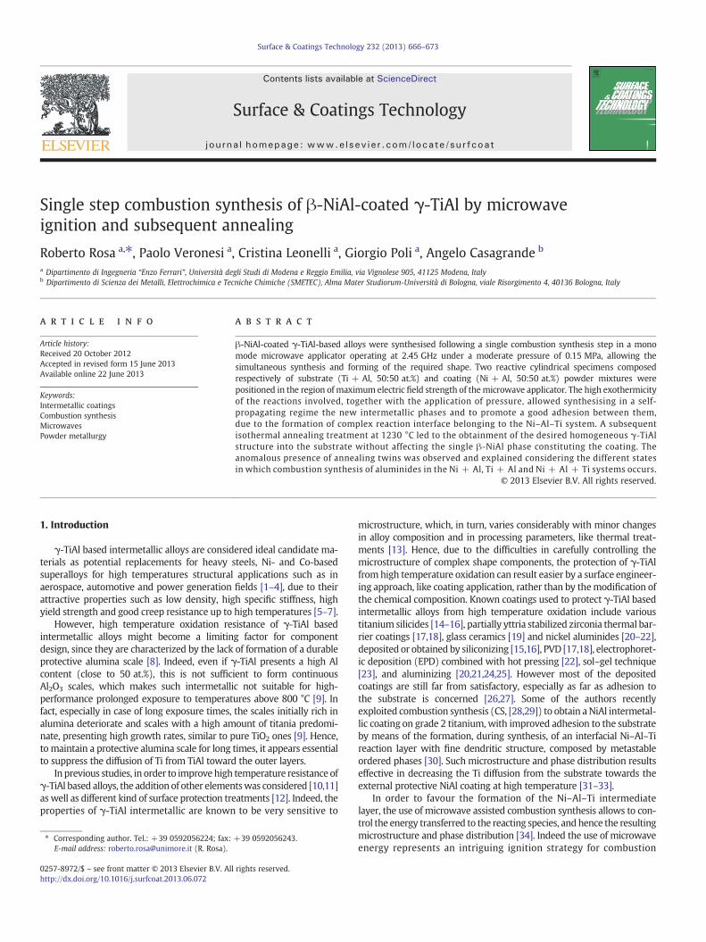
Particularly, Fig. 2A shows the polycrystalline outer coating layermade of equiaxed NiAl grains without preferential orientation. Despitethe small number of grains reported in the micrograph, the absenceof preferential orientation is also confirmed by the X-ray diffractionpattern of the NiAl coating, as discussed afterward in this section. InFig. 2B the reaction interface between the NiAl coating (left side ofFig. 2B) and Ti–Al intermetallics-based substrate (right side of Fig. 2B)is reported. The typical microstructure of the as combustion synthesisedTi–Al based substrate, consisting of dispersed spherical-shape brighterparticles, is reported in Fig. 2C. In order to obtain a deeper insight intothe microstructure as well as the chemical composition of the as com-bustion synthesised phases constituting the coating-substrate couple,scanning electron microscopy was performed together with EDS micro-analysis. The backscattered electron SEM micrograph of a typical trans-versal cross section of the sample after the CS is shown in Fig. 3.
The as synthesised samples consist of a denser coating (right partof Fig. 3), in correspondence of the former Ni + Al powders disc,lying on a more porous and thicker substrate, in correspondence ofthe former Ti + Al powders disc (left part of Fig. 3). The coatinglayer is homogenous and polycrystalline and EDS analysis (notreported) confirmed that it has a Ni:Al molar ratio of 1.
In Fig. 4 are reported magnified backscattered electron images ofthe as combustion synthesised Ti–Al substrate, showing a coarse,globular morphology, with a dispersion of 10–20 μm spheroidal par-ticles embedded in a darker matrix. Semi quantitative EDS analysisperformed in the three main distinguishable regions (A, B, and C) ofone of the spherical particles is reported in Fig. 4 as well.
The whiter zones correspond to the core of the former Ti particles,where no Al diffused during the occurrence of the rapid combustionsynthesis; moving outward from the Ti cores, an increasing Al contentis detected, corresponding to titanium aluminide phases formation.The results of EDS analysis show the variable composition existingin the Ti + Al region of the sample, probably due to the very shorttime of interdiffusion allowed by the CS process (few seconds) and,overall, to the much lower enthalpy of reaction of the titaniumaluminides formation (TiAl and Ti3Al ΔHf values are −75.3 kJ/moland −100 kJ/mol respectively [44,46]) with respect to the nickelaluminides ones (NiAl ΔHf = −118 kJ/mol [47]).
As a matter of facts, considering the adiabatic temperature, only1340 °C is reported for the formation of the first intermetallic, TiAl3,which possesses the lowest free energy of formation among the pos-sible Ti–Al intermetallics [48]. As suggested by the EDS results, thisdoes not preclude the nucleation and growth of other equilibrium ti-tanium richer phases, as Ti3Al, around the titanium powder particlesby diffusion in solid state.
Combustion synthesis of Ti + Al powder mixtures is driven by liq-uid Al–solid Ti interactions, and the ignition occurs only after the sup-plied energy had melted the aluminium. Hence, from the formation ofthe first liquid phase, a small amount of Ti–Al intermetallic startsforming on the Ti particle surface. However, this occurs without
interface and (C) Ti–Al intermetallics-based substrate.
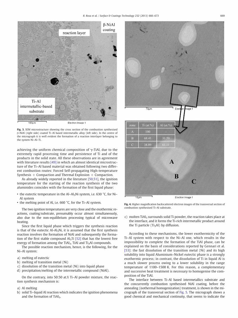
Fig. 3. SEM microstructure showing the cross section of the combustion synthesisedβ-NiAl (right side) coated Ti–Al based intermetallic alloy (left side). In the centre ofthe micrograph it is well evident the formation of a reaction interlayer belonging tothe system Ni–Al–Ti.
Fig. 4. Higher magnification backscattered electron images of the transversal section ofcombustion synthesised Ti–Al substrate.
669R. Rosa et al. / Surface & Coatings Technology 232 (2013) 666–673
achieving the uniform chemical composition of γ-TiAl, due to theextremely rapid processing time and persistence of Ti and of theproducts in the solid state. All these observations are in agreementwith literature results [49] in which an almost identical microstruc-ture of the Ti–Al based material was obtained following two differ-ent combustion routes: Forced Self-propagating High-temperatureSynthesis + Compaction and Thermal Explosion + Compaction.
As already widely reported in the literature [50,51], the ignitiontemperature for the starting of the reaction synthesis of the twoaluminides coincides with the formation of the first liquid phase:
• the eutectic temperature in the Al–Al3Ni system, i.e. 630 °C, for Ni–Al system
• the melting point of Al, i.e. 660 °C, for the Ti–Al system.
The two ignition temperatures are very close and the exothermic re-actions, coating/substrate, presumably occur almost simultaneously,also due to the non-equilibrium processing typical of microwaveheating.
Since the first liquid phase which triggers the synthesis reactionis that of the eutectic Al-Al3Ni, it is assumed that the first synthesisreaction involves the formation of NiAl and subsequently the forma-tion of the first stable compound Al3Ti [52] that has the lowest freeenergy of formation among the TiAl3, TiAl and Ti3Al compounds.
The possible reaction mechanism, hence, is the following, for theNi–Al system:
a) melting of eutecticb) melting of transition metal (Ni)c) dissolution of the transition metal (Ni) into liquid phased) precipitation/melting of the intermetallic compound (NiAl).
On the contrary, into 50:50 at.% Ti–Al powder mixture, the reac-tion synthesis mechanism is:
a) Al meltingb) solid Ti–liquid Al reaction which indicates the ignition phenomena
and the formation of TiAl3.
c) molten TiAl3 surrounds solid Ti powder, the reaction takes place atthe interface, and it forms the Ti-rich intermetallic product aroundthe Ti particle (Ti3Al) by diffusion.
According to these mechanisms, the lower exothermicity of theTi–Al system with respect to the Ni–Al one, which results in theimpossibility to complete the formation of the TiAl phase, can beexplained on the basis of considerations reported by Gennari et al.[53]: the fast dissolution of the transition metal (Ni) and its highsolubility into liquid Aluminium–Nickel eutectic phase is a stronglyexothermic process; in contrast, the dissolution of Ti in liquid Al isa much slower process owing to a lower solubility in the rangetemperature of 1100–1500 K. For this reason, a complementaryand successive heat treatment is necessary to homogenise the com-position of the TiAl.
The interface between Ti–Al based intermetallics substrate andthe concurrently combustion synthesised NiAl coating, before theannealing (isothermal homogenization) treatment, is shown in the mi-crograph of the transversal section of Fig. 5. The micrograph shows agood chemical and mechanical continuity, that seems to indicate the
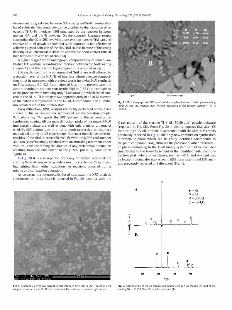
Fig. 6. SEM micrograph and EDS results of the interface between β-NiAl phase coating(zone A) and the reaction layer formed, belonging to the ternary system Ni–Al–Ti(zone B).
670 R. Rosa et al. / Surface & Coatings Technology 232 (2013) 666–673
obtainment of a good joint, betweenNiAl coating and Ti-Al intermetallic-based substrate. This continuity can be ascribed to the formation of aneutectic Ti–Al–Ni interlayer [30] originated by the reaction betweenmolten NiAl and the Ti powders. On the contrary, literature resultsconcerning the CS or SHS involving a pre-existing massive TiAl part andreactive Ni + Al powders show that such approach is not effective inachieving a good adhesion of the NiAl/TiAl couple, because of the strongbonding of an intermetallic structure and the too short contact time athigh temperature with liquid NiAl [54].
A higher magnification micrograph, comprehensive of semi quan-titative EDS analysis, regarding the interface between the NiAl coating(region A) and the reaction layer (region B) is reported in Fig. 6.
EDS results confirm the obtainment of NiAl phase well adhered toa reaction layer at the NiAl/Ti–Al interface whose average composi-tion is not in agreement with previous works involving NiAl synthesison Ti substrates [30–32]. As a matter of fact, in the present case, theatomic aluminium composition results higher (~55%) in comparisonto the previous work involving only Ti substrate (in which the Al con-tent in the Ni–Al–Ti interlayer was approximately of 15 at.%) becauseat the eutectic temperature of the Ni–Al–Ti compound, the alumini-um powders are in the molten state.
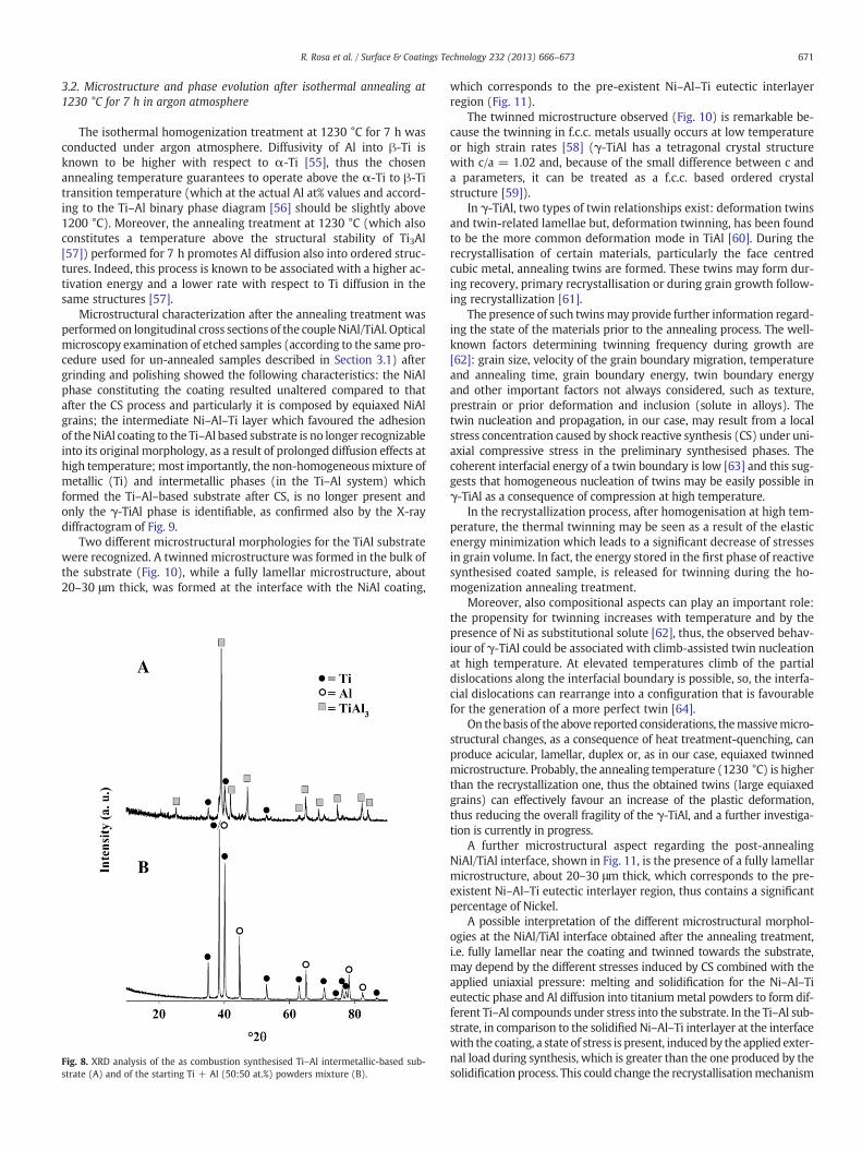
X-ray diffraction (XRD) analysis was firstly performed on the outersurface of the as combustion synthesised substrate-coating couple.Particularly Fig. 7A reports the XRD pattern of the as combustionsynthesised coating. All the main diffraction peaks of the single β-NiAlintermetallic phase are well evident with only a minor amount ofα-Al2O3 diffractions due to a not enough-protective atmospheremaintained during the CS experiments. Moreover the relative peaks in-tensities of the NiAl intermetallic well fit with the JCPDS card number44-1188 (experimentally obtained with an annealing treatment undervacuum), thus confirming the absence of any preferential orientationresulting from the obtainment of the β-NiAl phase by combustionsynthesis.
In Fig. 7B it is also reported the X-ray diffraction profile of thestarting Ni + Al compacted powders mixture (i.e. before CS ignition),highlighting that neither oxidation nor reactions occurred duringmixing and compaction operations.
As concerns the intermetallic-based substrate, the XRD analysis(performed on its surface) is reported in Fig. 8A together with the
Fig. 5. Scanning electron micrograph of the interface between Ni–Al–Ti reaction area(upper left corner), and Ti–Al based intermetallics substrate (bottom right corner).
X-ray pattern of the starting Ti + Al (50:50 at.%) powder mixture(reported in Fig. 8B). From Fig. 8A it clearly appears that after CSthe starting Ti is still present, in agreement with the SEM-EDS resultspreviously reported in Fig. 4. The only new combustion synthesisedintermetallic phase which can be easily identified corresponds tothe point compound TiAl3, although the presence of other intermetal-lic phases belonging to the Ti–Al binary system cannot be excluded(mainly due to the broad basement of the identified TiAl3 main dif-fraction peak, where other phases, such as γ-TiAl and α2-Ti3Al, canbe located) taking also into account SEM observations and EDS anal-ysis previously reported and discussed (Fig. 4).
Fig. 7. XRD analysis of the as combustion synthesised β-NiAl coating (A) and of thestarting Ni + Al (50:50 at.%) powders mixture (B).
671R. Rosa et al. / Surface & Coatings Technology 232 (2013) 666–673
3.2. Microstructure and phase evolution after isothermal annealing at1230 °C for 7 h in argon atmosphere
The isothermal homogenization treatment at 1230 °C for 7 h wasconducted under argon atmosphere. Diffusivity of Al into β-Ti isknown to be higher with respect to α-Ti [55], thus the chosenannealing temperature guarantees to operate above the α-Ti to β-Titransition temperature (which at the actual Al at% values and accord-ing to the Ti–Al binary phase diagram [56] should be slightly above1200 °C). Moreover, the annealing treatment at 1230 °C (which alsoconstitutes a temperature above the structural stability of Ti3Al[57]) performed for 7 h promotes Al diffusion also into ordered struc-tures. Indeed, this process is known to be associated with a higher ac-tivation energy and a lower rate with respect to Ti diffusion in thesame structures [57].
Microstructural characterization after the annealing treatment wasperformed on longitudinal cross sections of the couple NiAl/TiAl. Opticalmicroscopy examination of etched samples (according to the same pro-cedure used for un-annealed samples described in Section 3.1) aftergrinding and polishing showed the following characteristics: the NiAlphase constituting the coating resulted unaltered compared to thatafter the CS process and particularly it is composed by equiaxed NiAlgrains; the intermediate Ni–Al–Ti layer which favoured the adhesionof theNiAl coating to the Ti–Al based substrate is no longer recognizableinto its original morphology, as a result of prolonged diffusion effects athigh temperature; most importantly, the non-homogeneousmixture ofmetallic (Ti) and intermetallic phases (in the Ti–Al system) whichformed the Ti–Al–based substrate after CS, is no longer present andonly the γ-TiAl phase is identifiable, as confirmed also by the X-raydiffractogram of Fig. 9.
Two different microstructural morphologies for the TiAl substratewere recognized. A twinned microstructure was formed in the bulk ofthe substrate (Fig. 10), while a fully lamellar microstructure, about20–30 μm thick, was formed at the interface with the NiAl coating,
Fig. 8. XRD analysis of the as combustion synthesised Ti–Al intermetallic-based sub-strate (A) and of the starting Ti + Al (50:50 at.%) powders mixture (B).
which corresponds to the pre-existent Ni–Al–Ti eutectic interlayerregion (Fig. 11).
The twinned microstructure observed (Fig. 10) is remarkable be-cause the twinning in f.c.c. metals usually occurs at low temperatureor high strain rates [58] (γ-TiAl has a tetragonal crystal structurewith c/a = 1.02 and, because of the small difference between c anda parameters, it can be treated as a f.c.c. based ordered crystalstructure [59]).
In γ-TiAl, two types of twin relationships exist: deformation twinsand twin-related lamellae but, deformation twinning, has been foundto be the more common deformation mode in TiAl [60]. During therecrystallisation of certain materials, particularly the face centredcubic metal, annealing twins are formed. These twins may form dur-ing recovery, primary recrystallisation or during grain growth follow-ing recrystallization [61].
The presence of such twinsmay provide further information regard-ing the state of the materials prior to the annealing process. The well-known factors determining twinning frequency during growth are[62]: grain size, velocity of the grain boundary migration, temperatureand annealing time, grain boundary energy, twin boundary energyand other important factors not always considered, such as texture,prestrain or prior deformation and inclusion (solute in alloys). Thetwin nucleation and propagation, in our case, may result from a localstress concentration caused by shock reactive synthesis (CS) under uni-axial compressive stress in the preliminary synthesised phases. Thecoherent interfacial energy of a twin boundary is low [63] and this sug-gests that homogeneous nucleation of twins may be easily possible inγ-TiAl as a consequence of compression at high temperature.
In the recrystallization process, after homogenisation at high tem-perature, the thermal twinning may be seen as a result of the elasticenergy minimization which leads to a significant decrease of stressesin grain volume. In fact, the energy stored in the first phase of reactivesynthesised coated sample, is released for twinning during the ho-mogenization annealing treatment.
Moreover, also compositional aspects can play an important role:the propensity for twinning increases with temperature and by thepresence of Ni as substitutional solute [62], thus, the observed behav-iour of γ-TiAl could be associated with climb-assisted twin nucleationat high temperature. At elevated temperatures climb of the partialdislocations along the interfacial boundary is possible, so, the interfa-cial dislocations can rearrange into a configuration that is favourablefor the generation of a more perfect twin [64].
On thebasis of the above reported considerations, themassivemicro-structural changes, as a consequence of heat treatment-quenching, canproduce acicular, lamellar, duplex or, as in our case, equiaxed twinnedmicrostructure. Probably, the annealing temperature (1230 °C) is higherthan the recrystallization one, thus the obtained twins (large equiaxedgrains) can effectively favour an increase of the plastic deformation,thus reducing the overall fragility of the γ-TiAl, and a further investiga-tion is currently in progress.
A further microstructural aspect regarding the post-annealingNiAl/TiAl interface, shown in Fig. 11, is the presence of a fully lamellarmicrostructure, about 20–30 μm thick, which corresponds to the pre-existent Ni–Al–Ti eutectic interlayer region, thus contains a significantpercentage of Nickel.
A possible interpretation of the different microstructural morphol-ogies at the NiAl/TiAl interface obtained after the annealing treatment,i.e. fully lamellar near the coating and twinned towards the substrate,may depend by the different stresses induced by CS combined with theapplied uniaxial pressure: melting and solidification for the Ni–Al–Tieutectic phase and Al diffusion into titaniummetal powders to form dif-ferent Ti–Al compounds under stress into the substrate. In the Ti–Al sub-strate, in comparison to the solidified Ni–Al–Ti interlayer at the interfacewith the coating, a state of stress is present, inducedby the applied exter-nal load during synthesis, which is greater than the one produced by thesolidification process. This could change the recrystallisationmechanism
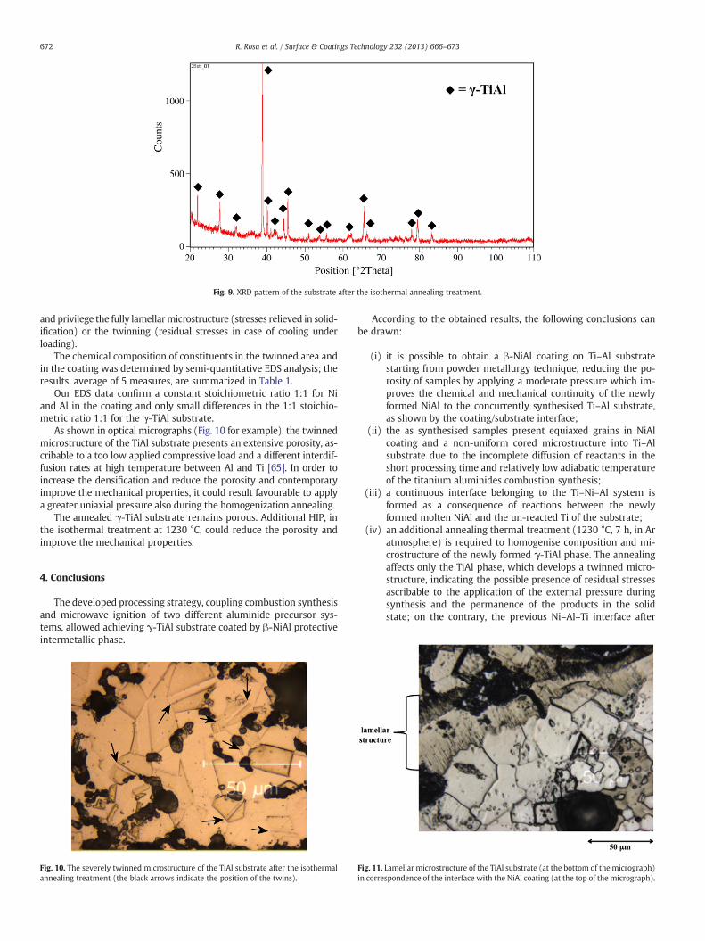
Fig. 9. XRD pattern of the substrate after the isothermal annealing treatment.
672 R. Rosa et al. / Surface & Coatings Technology 232 (2013) 666–673
and privilege the fully lamellarmicrostructure (stresses relieved in solid-ification) or the twinning (residual stresses in case of cooling underloading).
The chemical composition of constituents in the twinned area andin the coating was determined by semi-quantitative EDS analysis; theresults, average of 5 measures, are summarized in Table 1.
Our EDS data confirm a constant stoichiometric ratio 1:1 for Niand Al in the coating and only small differences in the 1:1 stoichio-metric ratio 1:1 for the γ-TiAl substrate.
As shown in optical micrographs (Fig. 10 for example), the twinnedmicrostructure of the TiAl substrate presents an extensive porosity, as-cribable to a too low applied compressive load and a different interdif-fusion rates at high temperature between Al and Ti [65]. In order toincrease the densification and reduce the porosity and contemporaryimprove the mechanical properties, it could result favourable to applya greater uniaxial pressure also during the homogenization annealing.
The annealed γ-TiAl substrate remains porous. Additional HIP, inthe isothermal treatment at 1230 °C, could reduce the porosity andimprove the mechanical properties.
4. Conclusions
The developed processing strategy, coupling combustion synthesisand microwave ignition of two different aluminide precursor sys-tems, allowed achieving γ-TiAl substrate coated by β-NiAl protectiveintermetallic phase.
Fig. 10. The severely twinned microstructure of the TiAl substrate after the isothermalannealing treatment (the black arrows indicate the position of the twins).
According to the obtained results, the following conclusions canbe drawn:
(i) it is possible to obtain a β-NiAl coating on Ti–Al substratestarting from powder metallurgy technique, reducing the po-rosity of samples by applying a moderate pressure which im-proves the chemical and mechanical continuity of the newlyformed NiAl to the concurrently synthesised Ti–Al substrate,as shown by the coating/substrate interface;
(ii) the as synthesised samples present equiaxed grains in NiAlcoating and a non-uniform cored microstructure into Ti–Alsubstrate due to the incomplete diffusion of reactants in theshort processing time and relatively low adiabatic temperatureof the titanium aluminides combustion synthesis;
(iii) a continuous interface belonging to the Ti–Ni–Al system isformed as a consequence of reactions between the newlyformed molten NiAl and the un-reacted Ti of the substrate;
(iv) an additional annealing thermal treatment (1230 °C, 7 h, in Aratmosphere) is required to homogenise composition and mi-crostructure of the newly formed γ-TiAl phase. The annealingaffects only the TiAl phase, which develops a twinned micro-structure, indicating the possible presence of residual stressesascribable to the application of the external pressure duringsynthesis and the permanence of the products in the solidstate; on the contrary, the previous Ni–Al–Ti interface after
Fig. 11. Lamellar microstructure of the TiAl substrate (at the bottom of the micrograph)in correspondence of the interface with the NiAl coating (at the top of the micrograph).
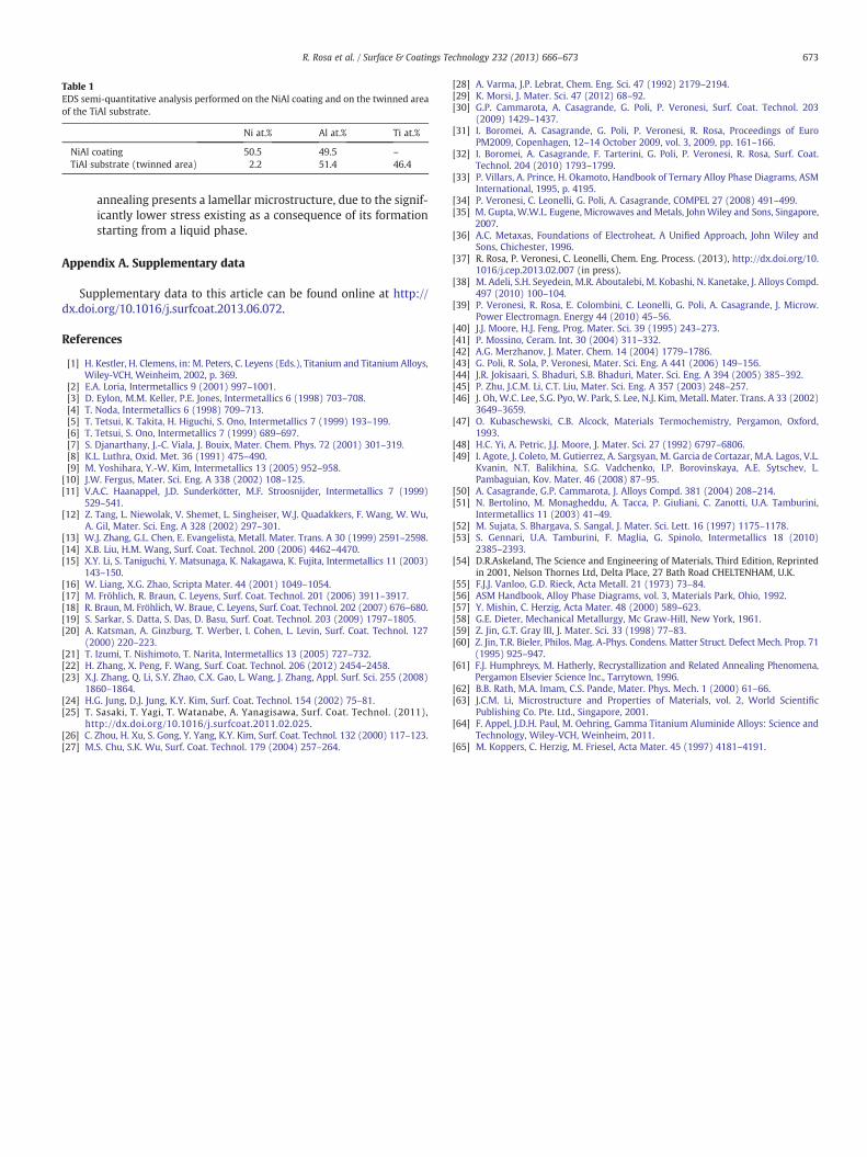
Table 1EDS semi-quantitative analysis performed on the NiAl coating and on the twinned areaof the TiAl substrate.
Ni at.% Al at.% Ti at.%
NiAl coating 50.5 49.5 –
TiAl substrate (twinned area) 2.2 51.4 46.4
673R. Rosa et al. / Surface & Coatings Technology 232 (2013) 666–673
annealing presents a lamellar microstructure, due to the signif-icantly lower stress existing as a consequence of its formationstarting from a liquid phase.
Appendix A. Supplementary data
Supplementary data to this article can be found online at http://dx.doi.org/10.1016/j.surfcoat.2013.06.072.
References
[1] H. Kestler, H. Clemens, in: M. Peters, C. Leyens (Eds.), Titanium and Titanium Alloys,Wiley-VCH, Weinheim, 2002, p. 369.
[2] E.A. Loria, Intermetallics 9 (2001) 997–1001.[3] D. Eylon, M.M. Keller, P.E. Jones, Intermetallics 6 (1998) 703–708.[4] T. Noda, Intermetallics 6 (1998) 709–713.[5] T. Tetsui, K. Takita, H. Higuchi, S. Ono, Intermetallics 7 (1999) 193–199.[6] T. Tetsui, S. Ono, Intermetallics 7 (1999) 689–697.[7] S. Djanarthany, J.-C. Viala, J. Bouix, Mater. Chem. Phys. 72 (2001) 301–319.[8] K.L. Luthra, Oxid. Met. 36 (1991) 475–490.[9] M. Yoshihara, Y.-W. Kim, Intermetallics 13 (2005) 952–958.
[10] J.W. Fergus, Mater. Sci. Eng. A 338 (2002) 108–125.[11] V.A.C. Haanappel, J.D. Sunderkötter, M.F. Stroosnijder, Intermetallics 7 (1999)
529–541.[12] Z. Tang, L. Niewolak, V. Shemet, L. Singheiser, W.J. Quadakkers, F. Wang, W. Wu,
A. Gil, Mater. Sci. Eng. A 328 (2002) 297–301.[13] W.J. Zhang, G.L. Chen, E. Evangelista, Metall. Mater. Trans. A 30 (1999) 2591–2598.[14] X.B. Liu, H.M. Wang, Surf. Coat. Technol. 200 (2006) 4462–4470.[15] X.Y. Li, S. Taniguchi, Y. Matsunaga, K. Nakagawa, K. Fujita, Intermetallics 11 (2003)
143–150.[16] W. Liang, X.G. Zhao, Scripta Mater. 44 (2001) 1049–1054.[17] M. Fröhlich, R. Braun, C. Leyens, Surf. Coat. Technol. 201 (2006) 3911–3917.[18] R. Braun, M. Fröhlich, W. Braue, C. Leyens, Surf. Coat. Technol. 202 (2007) 676–680.[19] S. Sarkar, S. Datta, S. Das, D. Basu, Surf. Coat. Technol. 203 (2009) 1797–1805.[20] A. Katsman, A. Ginzburg, T. Werber, I. Cohen, L. Levin, Surf. Coat. Technol. 127
(2000) 220–223.[21] T. Izumi, T. Nishimoto, T. Narita, Intermetallics 13 (2005) 727–732.[22] H. Zhang, X. Peng, F. Wang, Surf. Coat. Technol. 206 (2012) 2454–2458.[23] X.J. Zhang, Q. Li, S.Y. Zhao, C.X. Gao, L. Wang, J. Zhang, Appl. Surf. Sci. 255 (2008)
1860–1864.[24] H.G. Jung, D.J. Jung, K.Y. Kim, Surf. Coat. Technol. 154 (2002) 75–81.[25] T. Sasaki, T. Yagi, T. Watanabe, A. Yanagisawa, Surf. Coat. Technol. (2011),
http://dx.doi.org/10.1016/j.surfcoat.2011.02.025.[26] C. Zhou, H. Xu, S. Gong, Y. Yang, K.Y. Kim, Surf. Coat. Technol. 132 (2000) 117–123.[27] M.S. Chu, S.K. Wu, Surf. Coat. Technol. 179 (2004) 257–264.
[28] A. Varma, J.P. Lebrat, Chem. Eng. Sci. 47 (1992) 2179–2194.[29] K. Morsi, J. Mater. Sci. 47 (2012) 68–92.[30] G.P. Cammarota, A. Casagrande, G. Poli, P. Veronesi, Surf. Coat. Technol. 203
(2009) 1429–1437.[31] I. Boromei, A. Casagrande, G. Poli, P. Veronesi, R. Rosa, Proceedings of Euro
PM2009, Copenhagen, 12–14 October 2009, vol. 3, 2009, pp. 161–166.[32] I. Boromei, A. Casagrande, F. Tarterini, G. Poli, P. Veronesi, R. Rosa, Surf. Coat.
Technol. 204 (2010) 1793–1799.[33] P. Villars, A. Prince, H. Okamoto, Handbook of Ternary Alloy Phase Diagrams, ASM
International, 1995, p. 4195.[34] P. Veronesi, C. Leonelli, G. Poli, A. Casagrande, COMPEL 27 (2008) 491–499.[35] M. Gupta, W.W.L. Eugene, Microwaves and Metals, JohnWiley and Sons, Singapore,
2007.[36] A.C. Metaxas, Foundations of Electroheat, A Unified Approach, John Wiley and
Sons, Chichester, 1996.[37] R. Rosa, P. Veronesi, C. Leonelli, Chem. Eng. Process. (2013), http://dx.doi.org/10.
1016/j.cep.2013.02.007 (in press).[38] M. Adeli, S.H. Seyedein, M.R. Aboutalebi, M. Kobashi, N. Kanetake, J. Alloys Compd.
497 (2010) 100–104.[39] P. Veronesi, R. Rosa, E. Colombini, C. Leonelli, G. Poli, A. Casagrande, J. Microw.
Power Electromagn. Energy 44 (2010) 45–56.[40] J.J. Moore, H.J. Feng, Prog. Mater. Sci. 39 (1995) 243–273.[41] P. Mossino, Ceram. Int. 30 (2004) 311–332.[42] A.G. Merzhanov, J. Mater. Chem. 14 (2004) 1779–1786.[43] G. Poli, R. Sola, P. Veronesi, Mater. Sci. Eng. A 441 (2006) 149–156.[44] J.R. Jokisaari, S. Bhaduri, S.B. Bhaduri, Mater. Sci. Eng. A 394 (2005) 385–392.[45] P. Zhu, J.C.M. Li, C.T. Liu, Mater. Sci. Eng. A 357 (2003) 248–257.[46] J. Oh, W.C. Lee, S.G. Pyo, W. Park, S. Lee, N.J. Kim, Metall. Mater. Trans. A 33 (2002)
3649–3659.[47] O. Kubaschewski, C.B. Alcock, Materials Termochemistry, Pergamon, Oxford,
1993.[48] H.C. Yi, A. Petric, J.J. Moore, J. Mater. Sci. 27 (1992) 6797–6806.[49] I. Agote, J. Coleto, M. Gutierrez, A. Sargsyan, M. Garcia de Cortazar, M.A. Lagos, V.L.
Kvanin, N.T. Balikhina, S.G. Vadchenko, I.P. Borovinskaya, A.E. Sytschev, L.Pambaguian, Kov. Mater. 46 (2008) 87–95.
[50] A. Casagrande, G.P. Cammarota, J. Alloys Compd. 381 (2004) 208–214.[51] N. Bertolino, M. Monagheddu, A. Tacca, P. Giuliani, C. Zanotti, U.A. Tamburini,
Intermetallics 11 (2003) 41–49.[52] M. Sujata, S. Bhargava, S. Sangal, J. Mater. Sci. Lett. 16 (1997) 1175–1178.[53] S. Gennari, U.A. Tamburini, F. Maglia, G. Spinolo, Intermetallics 18 (2010)
2385–2393.[54] D.R.Askeland, The Science and Engineering of Materials, Third Edition, Reprinted
in 2001, Nelson Thornes Ltd, Delta Place, 27 Bath Road CHELTENHAM, U.K.[55] F.J.J. Vanloo, G.D. Rieck, Acta Metall. 21 (1973) 73–84.[56] ASM Handbook, Alloy Phase Diagrams, vol. 3, Materials Park, Ohio, 1992.[57] Y. Mishin, C. Herzig, Acta Mater. 48 (2000) 589–623.[58] G.E. Dieter, Mechanical Metallurgy, Mc Graw-Hill, New York, 1961.[59] Z. Jin, G.T. Gray III, J. Mater. Sci. 33 (1998) 77–83.[60] Z. Jin, T.R. Bieler, Philos. Mag. A-Phys. Condens. Matter Struct. Defect Mech. Prop. 71
(1995) 925–947.[61] F.J. Humphreys, M. Hatherly, Recrystallization and Related Annealing Phenomena,
Pergamon Elsevier Science Inc., Tarrytown, 1996.[62] B.B. Rath, M.A. Imam, C.S. Pande, Mater. Phys. Mech. 1 (2000) 61–66.[63] J.C.M. Li, Microstructure and Properties of Materials, vol. 2, World Scientific
Publishing Co. Pte. Ltd., Singapore, 2001.[64] F. Appel, J.D.H. Paul, M. Oehring, Gamma Titanium Aluminide Alloys: Science and
Technology, Wiley-VCH, Weinheim, 2011.[65] M. Koppers, C. Herzig, M. Friesel, Acta Mater. 45 (1997) 4181–4191.