A Continuous β-NiAl Layer Forming at the Interface of...
30
A Continuous β-NiAl Layer Forming at the Interface of a MCrAlY and CMSX-4 Kang Yuan, Ru Peng and Xin-Hai Li Linköping University Post Print N.B.: When citing this work, cite the original article. The original publication is available at www.springerlink.com: Kang Yuan, Ru Peng and Xin-Hai Li, A Continuous β-NiAl Layer Forming at the Interface of a MCrAlY and CMSX-4, 2016, Journal of thermal spray technology (Print), (25), 1, 244-251. http://dx.doi.org/10.1007/s11666-015-0293-4 Copyright: Springer Verlag (Germany) http://www.springerlink.com/?MUD=MP Postprint available at: Linköping University Electronic Press http://urn.kb.se/resolve?urn=urn:nbn:se:liu:diva-123740
Transcript of A Continuous β-NiAl Layer Forming at the Interface of...
A Continuous β-NiAl Layer Forming at the Interface of a MCrAlY and CMSX-4
Kang Yuan, Ru Peng and Xin-Hai Li
Linköping University Post Print
N.B.: When citing this work, cite the original article.
The original publication is available at www.springerlink.com:
Kang Yuan, Ru Peng and Xin-Hai Li, A Continuous β-NiAl Layer Forming at the Interface of a MCrAlY and CMSX-4, 2016, Journal of thermal spray technology (Print), (25), 1, 244-251. http://dx.doi.org/10.1007/s11666-015-0293-4 Copyright: Springer Verlag (Germany)
http://www.springerlink.com/?MUD=MP
Postprint available at: Linköping University Electronic Press
http://urn.kb.se/resolve?urn=urn:nbn:se:liu:diva-123740
1
A Continuous β-NiAl Layer Forming at the Interface of a MCrAlY
and CMSX-4
Kang Yuan1, Ru Lin Peng1,*, Xin-Hai Li2
1Department of Management and Engineering, Linkoping University, SE-58183 Linkoping, Sweden
2Siemens Industrial Turbomachinery AB, SE-61283 Finspång, Sweden
*Corresponding author: E-mail: [email protected]
Keywords: β-layer; CMSX-4; MCrAlY; diffusion; Al activity.
Abstract.
A large test sample of single crystal superalloy (CMSX-4) deposited with a MCrAlY
coating of γ and β phases was subjected to a thermal-cycling fatigue (TCF) test at 1100 °C for
about 300 cycles. Near the coating-substrate interface where an inner β-depletion zone often
develops in the coating for other superalloy-MCrAlY systems, a continuous β-layer was formed
instead for this particular system after the TCF test. The formation of the β-layer was related to
the accumulation of Al at the interface. Simulations using an oxidation-diffusion model were
carried out on this and a number of other superalloy-MCrAlY systems. It was derived that the
formation of the β-layer at the interface was likely due to the high Al activity of CMSX-4 which
resisted the inward diffusion of Al from the coating. The simulation results also indicated a
positive effect provided by the formation of the β-layer on the coating’s oxidation resistance.
1. Introduction
2
MCrAlY (M=Ni, Co) coatings are widely used as overlays or bond coats in thermal
barrier coating (TBC) systems in aerospace engines and industrial gas turbines nowadays [1-3].
In an oxidation process at high temperature, a thermally-grown oxide (TGO), preferably
alumina, forms at the MCrAlY coating surface and protects the underlying material from
oxidation and corrosion. In a MCrAlY coating, the Al-rich β-NiAl phase, as Al reservoir,
provides the coating surface with Al needed to maintain the protective TGO. Under continued
thermal exposure, continued oxidation at the coating surface consumes Al in the coating and
thus the β-phase. In addition, the coating also loses Al into the substrates due to the inter-
diffusion of alloying elements through coating-substrate interface (the substrate is considered
to be an Al sink), leading to the development of an inner β-depletion zone of the coating near
the interface [4,5]. If the diffusion of Al from the coating into the substrate can be hindered or
slowed, more Al will be available for maintaining the protective TGO and therefore the coating
life can be prolonged.
This paper is an extension of the ITSC2015 paper [6]. In the study, a continuous β-NiAl
layer was observed to form automatically at the coating-substrate interface in a system of
CMSX-4 substrate with a MCrAlY coating during a thermal cyclic test. Such a continuous β-
layer may contribute to a better coating life as it can serve as an effective Al reservoir. The
mechanism of the formation of the β-layer was analyzed based on experimental study and
diffusion modeling.
2. Experiments and model setting-up
A large test sample of single crystal CMSX-4 was coated with a TBC system. The TBC
was composed of a top coat (yttria-stabilized zirconia) and a MCrAlY bond coat. Both the top
coat and the bond coat were deposited by electron-beam physical-vapor deposition (EB-PVD)
3
technique. The compositions of the MCrAlY coating (c1) and the CMSX-4 substrate (s1) are
presented in Table 1. Table 1 also gives the compositions of other coatings and substrates which
were used for diffusion modeling in this paper.
The sample was tested in a thermal-cycling fatigue (TCF) rig. Each TCF cycle contained
one-hour heating at 1100 °C in air and 10-min forced-air cooling to about 100 °C. The test was
stopped after about 300 cycles. The cross section of the tested sample was finally investigated
in a scanning electron microscope (SEM) equipped with an energy dispersive spectrometer
(EDS) and an electron back-scattered diffraction (EBSD) detector.
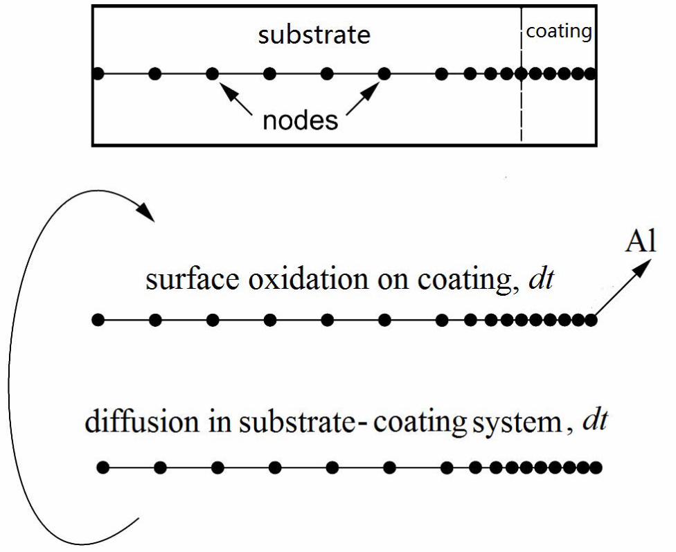
A developed oxidation-diffusion model [4,7,8] was adopted to study the influence of
heating at 1100 °C on systems combining the substrates and coatings given in Table 1. The
modelling scheme is as follows (Fig. 1): 1) Al was removed from the outmost nodes to simulate
the consumption of Al due to surface oxidation, 2) a homogenization diffusion simulation was
done in the coating-substrate system using the DICTRA software from Thermo-Calc, 3) the
previous two steps were cycled until the predetermined heating time was reached. The
diffusivities of alloying elements at 1100 °C were calculated in DICTRA software using the
Ni-based databases (TCNI6 and MOBNI2) from Thermo-Calc. The oxidation rate of the
coatings used in the model was described by a parabolic law as shown in Eq. 1.
h=h0+(kp*t)0.5 (1)
In Eq.1, h is TGO thickness (unit: μm), t is time (unit: hour), h0 is original TGO
thickness which was simply set as zero for the modeling in this paper, kp is the oxidation
constant which from fitting to experimental data was found to be 0.157 μm2/h.
4
3. Results
3.1. Experimental observations in s1-c1 sample
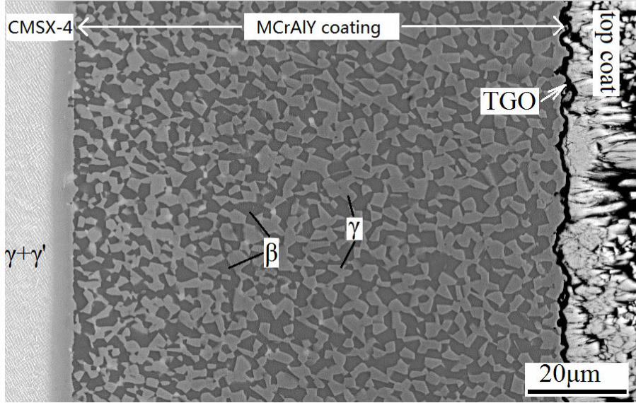
Fig. 2 shows a cross section of the s1-c1 sample before the TCF test. A typical γ/β
microstructure formed in the MCrAlY coating, while a γ/γ’ microstructure existed in the single
crystal CMSX-4. The β-phase was Al-rich (17 wt.%) and the γ-phase was Al-poor (4.6 wt.%).
Between the top coat and the MCrAlY bond coat, a TGO of alumina was found (< 0.5 μm). The
TGO grew to about 7 μm after around 300 TCF cycles.
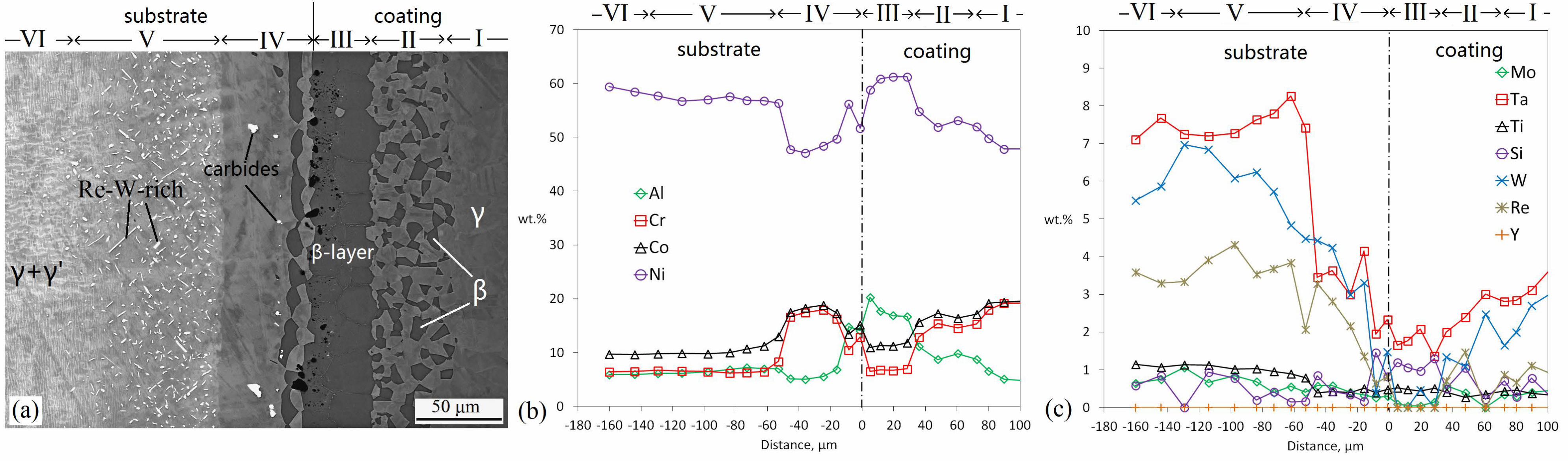
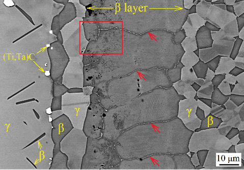
The microstructure in the sample changed during the TCF process; the developed
microstructure after about 300 cycles is shown in Fig. 3a. As can be seen, the inner β-depletion
zone, which is commonly found in superalloy-MCrAlY systems exposed to high temperatures,
was absent in the current system. Instead, a continuous β-layer formed at the coating-substrate
interface.
The cross section of the β-layer sample can be divided into six characteristic zones,
shown in Fig. 3a. Zone I was the OBDZ. Zone II had a typical γ/β microstructure. Zone III
contained the β-layer. Zone IV was the GPDZ, in which some secondary β-phase and (Ta,Ti)-
carbides also formed. In zone V, many (Re, W)-rich precipitates (identified as the µ-phase by
EBSD measurement) formed in a γ/γ’ matrix of γ’-rich. Zone VI was the unaffected substrate
with γ/γ’.
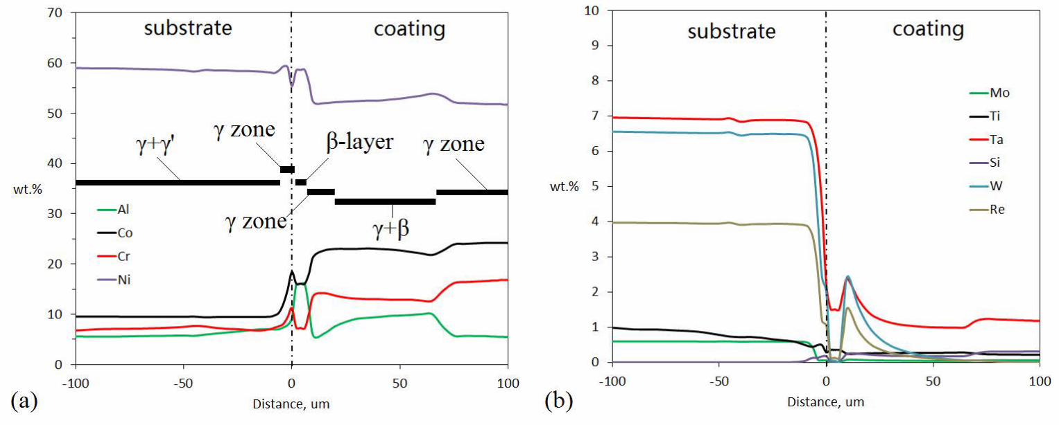
The chemical concentration profiles in Fig. 3b and c indicated that extensive diffusion
had occurred, resulting in the complex microstructural changes observed on both sides of the
coating-substrate interface. Co and Cr diffused from the coating to the substrate while Ni moved
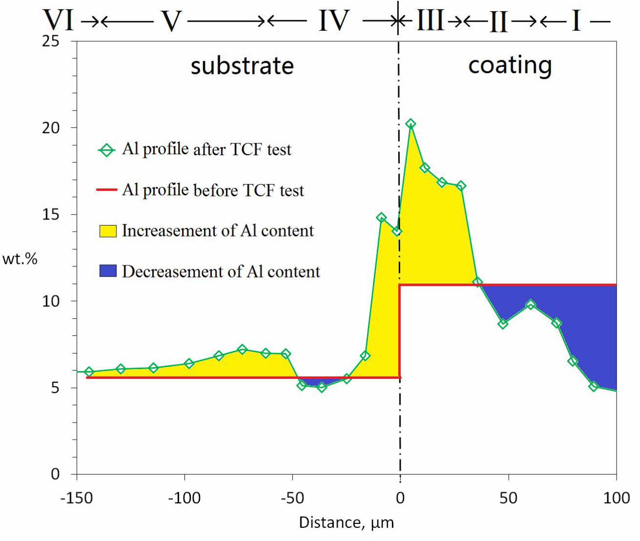
in the opposite direction (Fig. 3b). The Al profile is particularly presented in Fig. 4. As it was
shown, some Al from the coating and from zone IV diffused into the substrate in zone V, while
5
some others from the coating were trapped at the coating-substrate interface, forming zone III
with up to 17% Al. Diffusion of elements like Ta, W, Re, Mo from the substrate into the coating
also occurred (Fig. 3c).
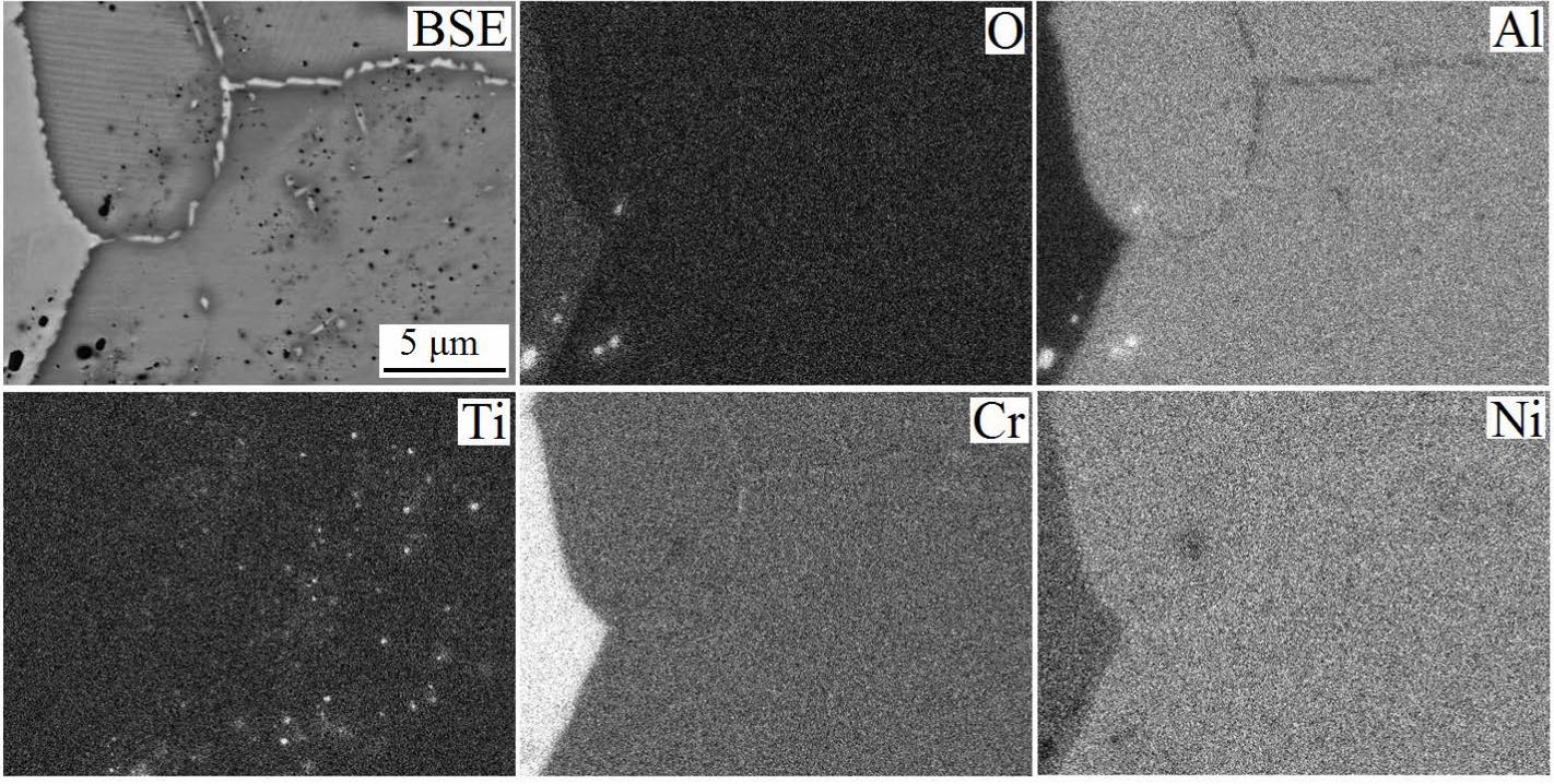
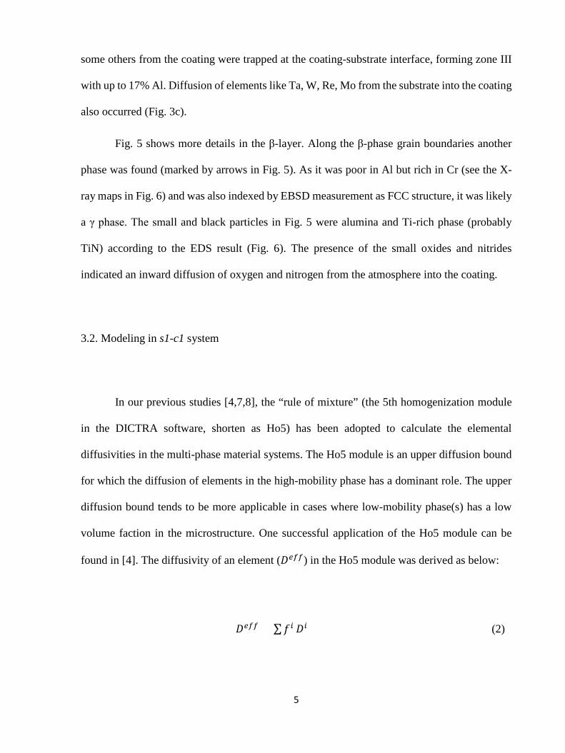
Fig. 5 shows more details in the β-layer. Along the β-phase grain boundaries another
phase was found (marked by arrows in Fig. 5). As it was poor in Al but rich in Cr (see the X-
ray maps in Fig. 6) and was also indexed by EBSD measurement as FCC structure, it was likely
a γ phase. The small and black particles in Fig. 5 were alumina and Ti-rich phase (probably
TiN) according to the EDS result (Fig. 6). The presence of the small oxides and nitrides
indicated an inward diffusion of oxygen and nitrogen from the atmosphere into the coating.
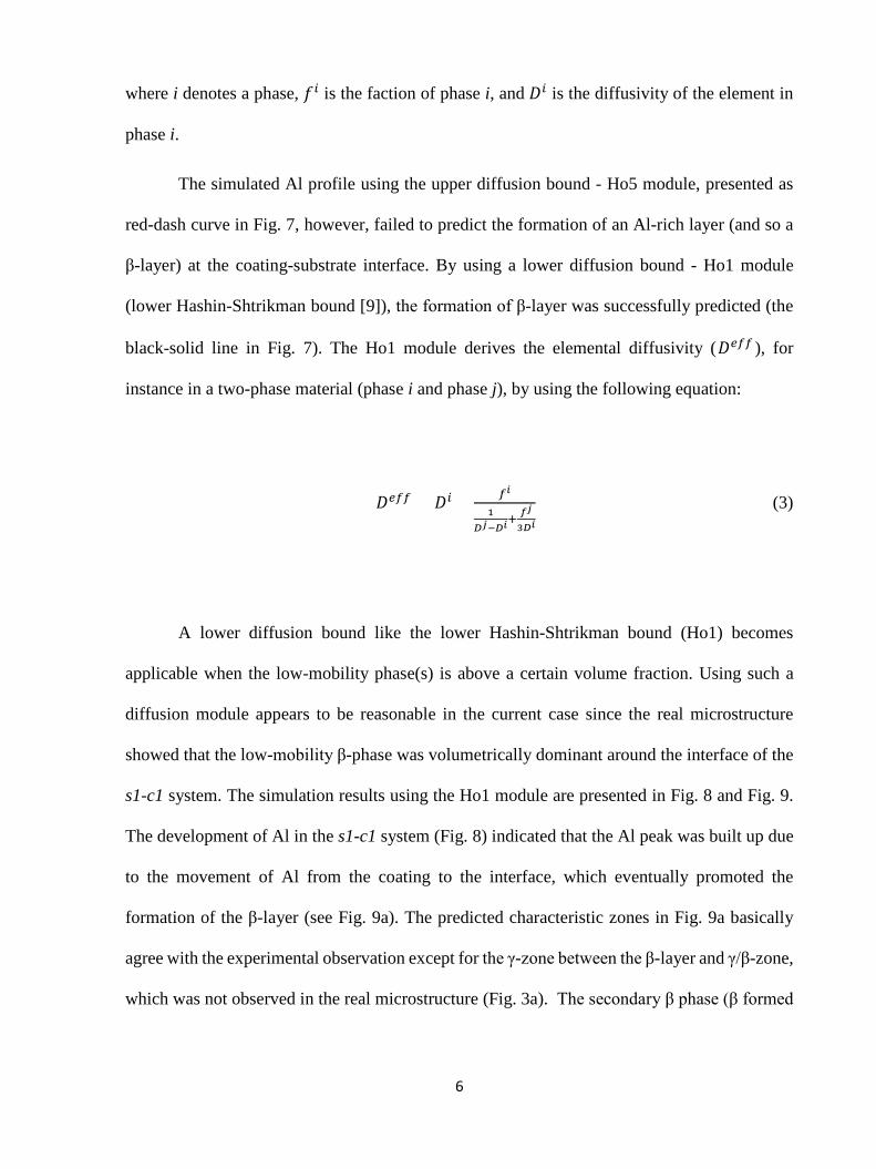
3.2. Modeling in s1-c1 system
In our previous studies [4,7,8], the “rule of mixture” (the 5th homogenization module
in the DICTRA software, shorten as Ho5) has been adopted to calculate the elemental
diffusivities in the multi-phase material systems. The Ho5 module is an upper diffusion bound
for which the diffusion of elements in the high-mobility phase has a dominant role. The upper
diffusion bound tends to be more applicable in cases where low-mobility phase(s) has a low
volume faction in the microstructure. One successful application of the Ho5 module can be
found in [4]. The diffusivity of an element (𝐷𝐷𝑒𝑒𝑒𝑒𝑒𝑒) in the Ho5 module was derived as below:
𝐷𝐷𝑒𝑒𝑒𝑒𝑒𝑒 = ∑𝑓𝑓𝑖𝑖 𝐷𝐷𝑖𝑖 (2)
6
where i denotes a phase, 𝑓𝑓𝑖𝑖 is the faction of phase i, and 𝐷𝐷𝑖𝑖 is the diffusivity of the element in
phase i.
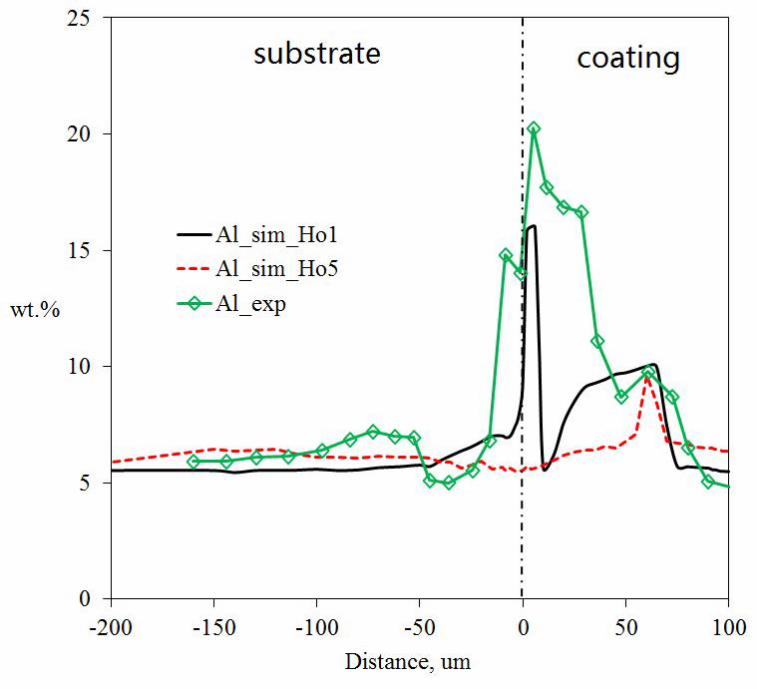
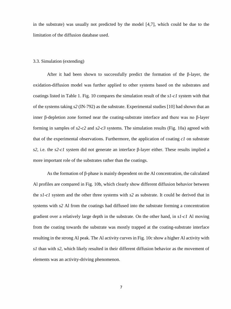
The simulated Al profile using the upper diffusion bound - Ho5 module, presented as
red-dash curve in Fig. 7, however, failed to predict the formation of an Al-rich layer (and so a
β-layer) at the coating-substrate interface. By using a lower diffusion bound - Ho1 module
(lower Hashin-Shtrikman bound [9]), the formation of β-layer was successfully predicted (the
black-solid line in Fig. 7). The Ho1 module derives the elemental diffusivity (𝐷𝐷𝑒𝑒𝑒𝑒𝑒𝑒 ), for
instance in a two-phase material (phase i and phase j), by using the following equation:
𝐷𝐷𝑒𝑒𝑒𝑒𝑒𝑒 = 𝐷𝐷𝑖𝑖 + 𝑒𝑒𝑖𝑖
1𝐷𝐷𝑗𝑗−𝐷𝐷𝑖𝑖
+ 𝑓𝑓𝑗𝑗
3𝐷𝐷𝑖𝑖
(3)
A lower diffusion bound like the lower Hashin-Shtrikman bound (Ho1) becomes
applicable when the low-mobility phase(s) is above a certain volume fraction. Using such a
diffusion module appears to be reasonable in the current case since the real microstructure
showed that the low-mobility β-phase was volumetrically dominant around the interface of the
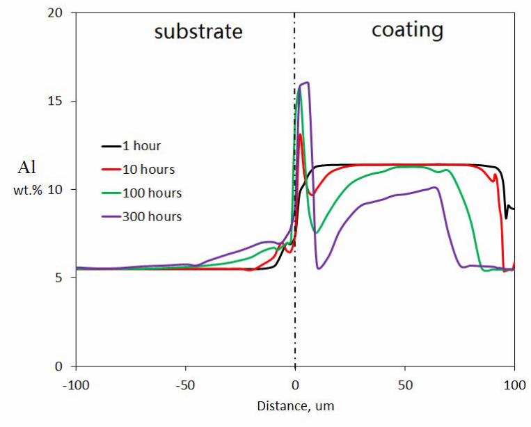
s1-c1 system. The simulation results using the Ho1 module are presented in Fig. 8 and Fig. 9.
The development of Al in the s1-c1 system (Fig. 8) indicated that the Al peak was built up due
to the movement of Al from the coating to the interface, which eventually promoted the
formation of the β-layer (see Fig. 9a). The predicted characteristic zones in Fig. 9a basically
agree with the experimental observation except for the γ-zone between the β-layer and γ/β-zone,
which was not observed in the real microstructure (Fig. 3a). The secondary β phase (β formed
7
in the substrate) was usually not predicted by the model [4,7], which could be due to the
limitation of the diffusion database used.
3.3. Simulation (extending)
After it had been shown to successfully predict the formation of the β-layer, the
oxidation-diffusion model was further applied to other systems based on the substrates and
coatings listed in Table 1. Fig. 10 compares the simulation result of the s1-c1 system with that
of the systems taking s2 (IN-792) as the substrate. Experimental studies [10] had shown that an
inner β-depletion zone formed near the coating-substrate interface and there was no β-layer
forming in samples of s2-c2 and s2-c3 systems. The simulation results (Fig. 10a) agreed with
that of the experimental observations. Furthermore, the application of coating c1 on substrate
s2, i.e. the s2-c1 system did not generate an interface β-layer either. These results implied a
more important role of the substrates rather than the coatings.
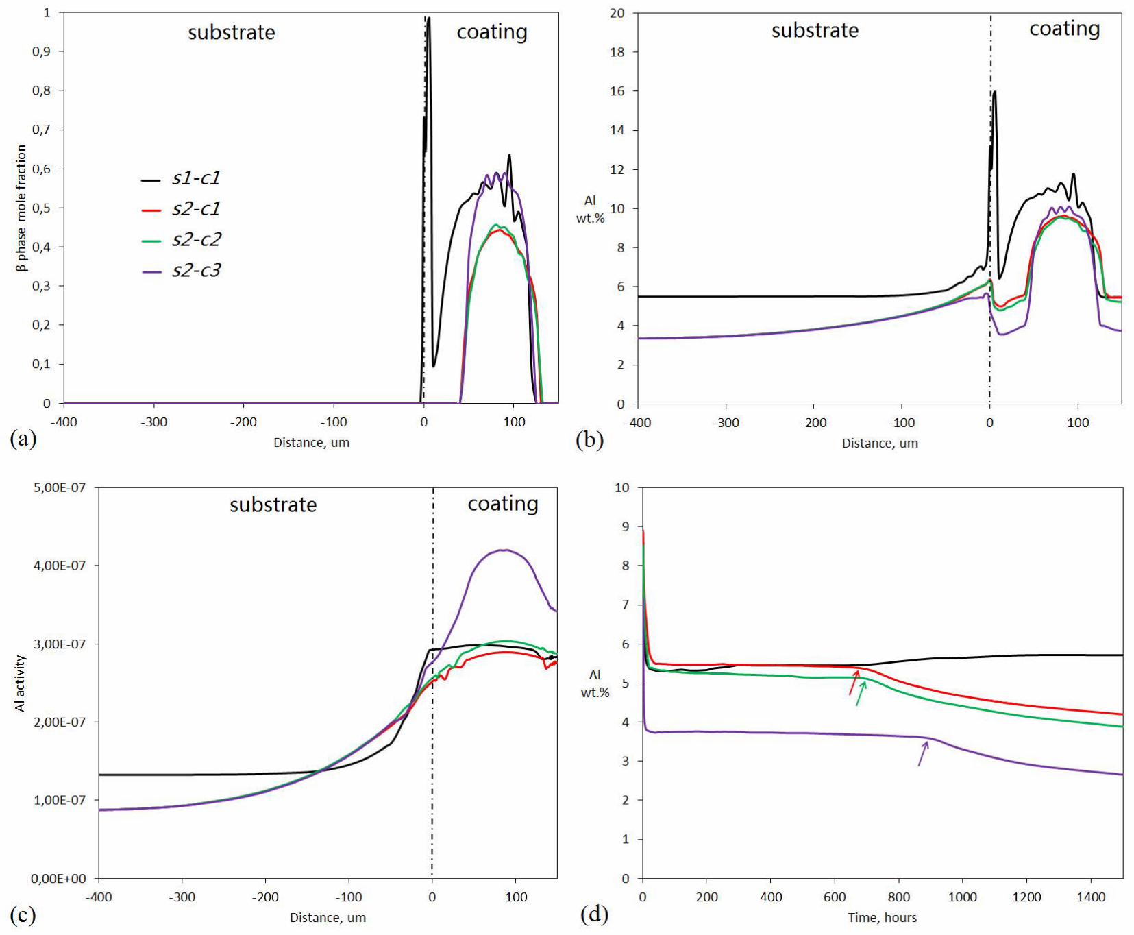
As the formation of β-phase is mainly dependent on the Al concentration, the calculated
Al profiles are compared in Fig. 10b, which clearly show different diffusion behavior between
the s1-c1 system and the other three systems with s2 as substrate. It could be derived that in
systems with s2 Al from the coatings had diffused into the substrate forming a concentration
gradient over a relatively large depth in the substrate. On the other hand, in s1-c1 Al moving
from the coating towards the substrate was mostly trapped at the coating-substrate interface
resulting in the strong Al peak. The Al activity curves in Fig. 10c show a higher Al activity with
s1 than with s2, which likely resulted in their different diffusion behavior as the movement of
elements was an activity-driving phenomenon.
8
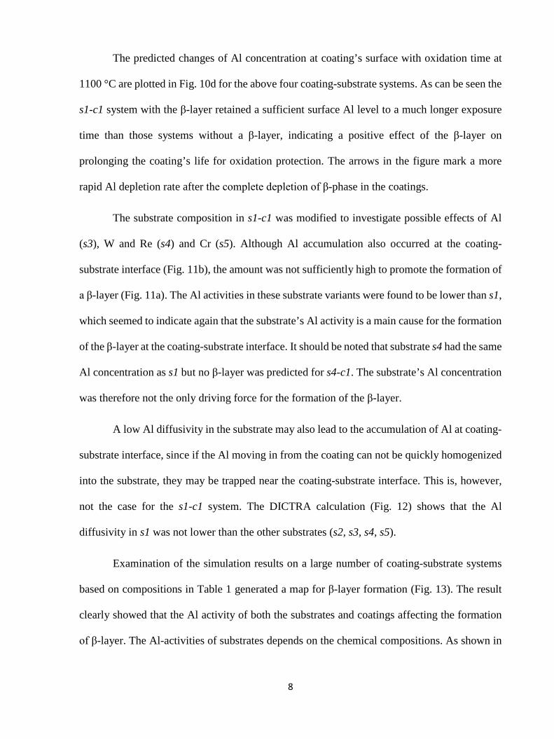
The predicted changes of Al concentration at coating’s surface with oxidation time at
1100 °C are plotted in Fig. 10d for the above four coating-substrate systems. As can be seen the
s1-c1 system with the β-layer retained a sufficient surface Al level to a much longer exposure
time than those systems without a β-layer, indicating a positive effect of the β-layer on
prolonging the coating’s life for oxidation protection. The arrows in the figure mark a more
rapid Al depletion rate after the complete depletion of β-phase in the coatings.
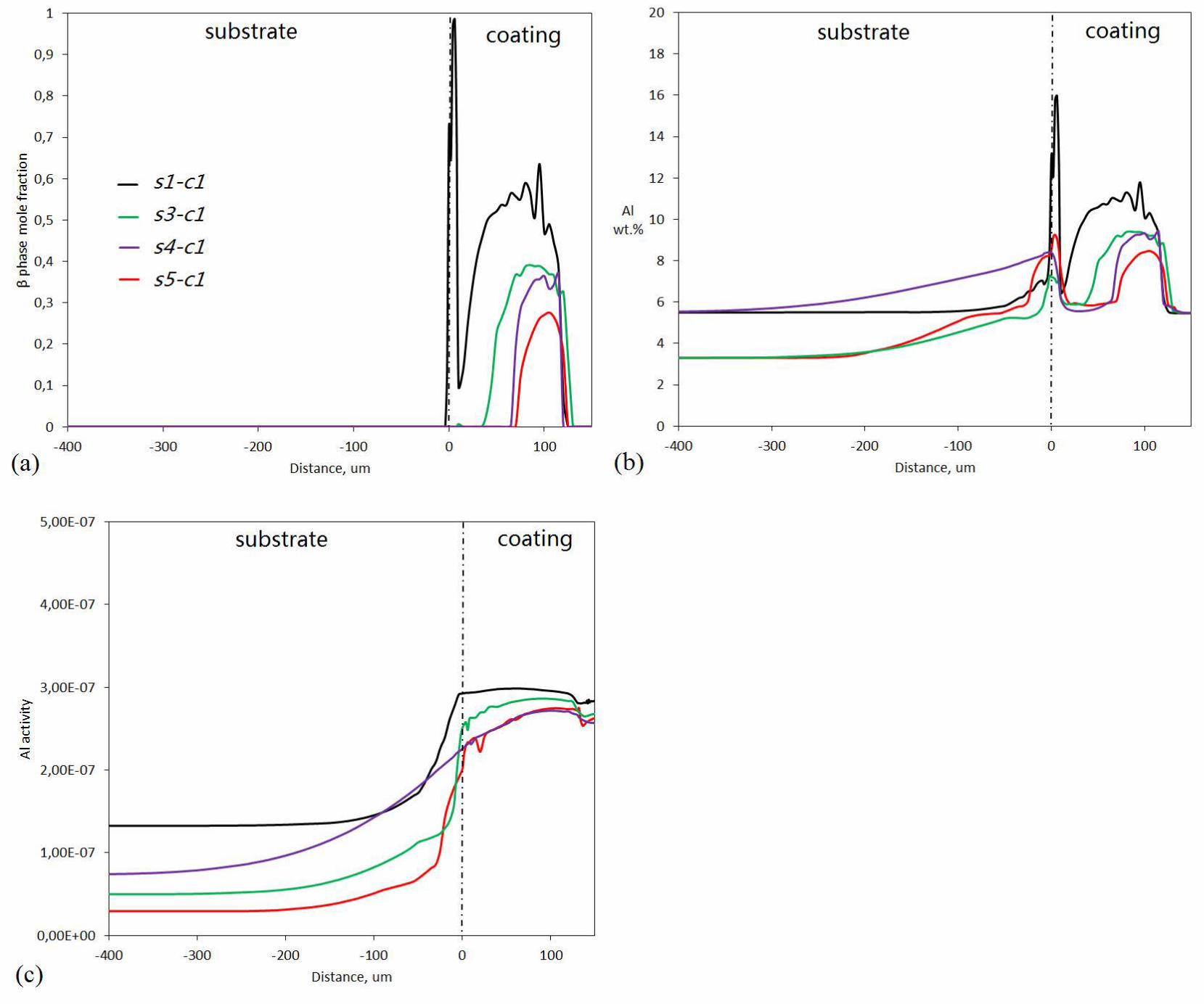
The substrate composition in s1-c1 was modified to investigate possible effects of Al
(s3), W and Re (s4) and Cr (s5). Although Al accumulation also occurred at the coating-
substrate interface (Fig. 11b), the amount was not sufficiently high to promote the formation of
a β-layer (Fig. 11a). The Al activities in these substrate variants were found to be lower than s1,
which seemed to indicate again that the substrate’s Al activity is a main cause for the formation
of the β-layer at the coating-substrate interface. It should be noted that substrate s4 had the same
Al concentration as s1 but no β-layer was predicted for s4-c1. The substrate’s Al concentration
was therefore not the only driving force for the formation of the β-layer.
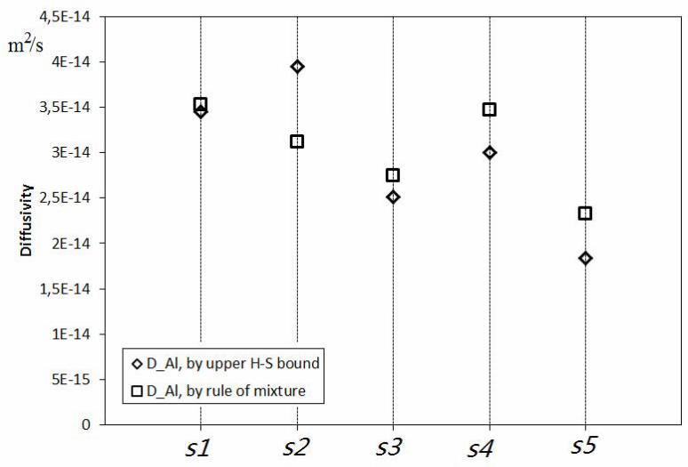
A low Al diffusivity in the substrate may also lead to the accumulation of Al at coating-
substrate interface, since if the Al moving in from the coating can not be quickly homogenized
into the substrate, they may be trapped near the coating-substrate interface. This is, however,
not the case for the s1-c1 system. The DICTRA calculation (Fig. 12) shows that the Al
diffusivity in s1 was not lower than the other substrates (s2, s3, s4, s5).
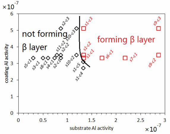
Examination of the simulation results on a large number of coating-substrate systems
based on compositions in Table 1 generated a map for β-layer formation (Fig. 13). The result
clearly showed that the Al activity of both the substrates and coatings affecting the formation
of β-layer. The Al-activities of substrates depends on the chemical compositions. As shown in
9
Table 2, it increased with increasing concentration of alloying elements like Al, Mo, Re, Cr, Ti,
etc (balanced by Ni).
4. Discussion
Whether or not a continuous β-layer can form in a coating-substrate system is largely
dependent on the behavior of the diffusion of elements especially the Al in the system. Both the
experimental work and simulations showed that β-depletion of the coating near the coating-
substrate interface which was observed in s2-c2 and s2-c3 was inhibited in the s1-c1 sample.
In another word, the inward diffusion of Al from the MCrAlY coating into the CMSX-4
substrate was slower than into the IN792 substrate. A substrate resisting inward diffusion of Al
seemed to be essential for the formation of the β-layer at the interface. Indeed the simulations
predicted a β-layer when c1, c2 or c3 was combined with a CMSX-4 substrate but no β-layer
when any of these coatings was applied on an IN792 substrate (Fig. 13). On the other hand, Fig.
13 also revealed the importance of the coating composition. No β-layer was expected when
coatings c4 and c5 were combined with a CMSX-4 substrate. c4 and c5 has a lower Al
concentration and thus lower Al activity than c1, c2 and c3.
Fig. 10d revealed that the formation of β-layer may prolong the coating’s oxidation life
by providing the coating surface with the Al needed to maintain a protective scale to a longer
thermal exposure time. The Al in the β-layer may be used only for forming Al oxide at coating
surface or also could diffuse into the substrate after a long thermal exposure time. Further work
with experiments and simulations are needed in the future to investigate the long term
interdiffusion and oxidation behavior of the s1-c1 system. Fig. 13 and Table 2 suggested that
10
increasing the substrate’s Al activity can increase the possibility of β-layer formation. While
increasing the Al concentration in the substrate seemed to be an efficient way to enhance the
Al activity, the substrate’s Al activity can also be enhanced via increasing the concentration of
elements of Cr, Ta, Mo and Re (Ni as the balanced element). This indicated that selecting or
tailoring the chemical composition to reduce the substrate’s sinking effect on Al could be an
effective way to enhance the oxidation resistance of the coated system.
5. Conclusion
A continuous β-NiAl layer was found near the coating-substrate interface in a sample
of CMSX-4 deposited with MCrAlY subjected to a thermal cycling testing (1100 °C, for about
300 hours). The experimental study and simulations using an oxidation-diffusion model showed
that the formation of the β-layer in this coating-substrate system was likely due to the high Al
activity of the CMSX-4 substrate. The high Al activity is believed to reduce the substrate’s
sinking effect on Al such that Al moving from a coating with a sufficient concentration of Al
towards the substrate is accumulated at the coating-substrate interface to form the β-layer. The
simulation results also showed a positive effect provided by the β-layer on the coating’s
oxidation resistance.
The results of the current work indicate the potential and possibility of enhancing
oxidation resistance of MCrAlY-superalloy systems by modifying superalloys composition to
sufficiently inhibit the sinking effect of the substrate on Al.
11
Acknowledgement
The Siemens Industrial Turbomachinery AB (Finspång, Sweden) is greatly
acknowledged for its financial support in this research. The authors are also grateful for KME
and Energiforsk in Sweden for their support and the Swedish Energy Agency for funding the
project.
References
[1] N.P. Padture, M. Gell, E.H. Jordan, Thermal Barrier Coatings for Gas-Turbine Engine Applications, Science, 2002, 296(5566), p 280-284
[2] D.J. Wortman, B.A. Nagaraj, E.C. Duderstadt, Thermal Barrier Coatings for Gas Turbine Use, Mater. Sci. Eng. A, 1989, 120–121, Part 2(0), p 433-440
[3] S. Bose and J. DeMasi-Marcin, Thermal Barrier Coating Experience in Gas Turbine Engines at Pratt & Whitney, J. Therm. Spray Technol., 1997, 6(1), p 99-104
[4] K. Yuan, R. Eriksson, R. Lin Peng, X. Li, S. Johansson, Y. Wang, Modeling of Microstructural Evolution and Lifetime Prediction of MCrAlY Coatings on Nickel Based Superalloys during High Temperature Oxidation, Surf. Coat. Technol., 2013, 232(0), p 204-215
[5] T. Gomez-Acebo, B. Navarcorena, F. Castro, Interdiffusion in Multiphase, Al-Co-Cr-Ni-Ti Diffusion Couples, J. Phase Equilib. Diffu., 2004, 25(3), p 237-251
[6] K. Yuan, R. Lin Peng, X. Li, A Continuous β-NiAl Layer Forming at the Interface of a MCrAlY and CMSX-4, ITSC 2015—Proceedings of the International Thermal Spray Conference, 2015, p 54-61
[7] K. Yuan, R. Eriksson, R. Lin Peng, X. Li, S. Johansson, Y. Wang, MCrAlY Coating Design Based on Oxidation-Diffusion Modelling. Part I: Microstructural Evolution, Surf. Coat. Technol., 2014, 254(0), p 79-96
[8] R. Eriksson, K. Yuan, X. Li, R. Lin Peng, MCrAlY Coating Design Based on Oxidation–diffusion Modelling. Part II: Lifing Aspects, Surf. Coat. Technol., 2014, 253(0), p 27-37
[9] Z. Hashin and S. Shtrikman, A Variational Approach to the Theory of the Effective Magnetic Permeability of Multiphase Materials, J. Appl. Phys., 1962, 33(10), p 3125-3131
12
[10] K. Yuan, R. Lin Peng, X. Li, S. Johansson, Y. Wang, Some Aspects of Elemental Behaviour in HVOF MCrAlY Coatings in High-Temperature Oxidation, Surf. Coat. Technol., 2015, 261(0), p 86-101
13
Figure captions:
Figure 1: Oxidation-diffusion model.
Figure 2: Cross section of c1-s1 sample in as-received status.
Figure 3. Cross section of c1-s1 sample after the TCF test: (a) microstructures, (b) and (c)
concentration profiles of elements across the cross section in figure (a).
Figure 4. Al concentration profile from Fig. 3b.
Figure 5. Microstructure details in the area with β layer.
Figure 6. EDS maps of some elements in the area marked by square in Fig. 5.
Figure 7. Simulated Al profile using oxidation-diffusion model (1100 °C and 300 hours). The
simulations used two homogenization modules: Ho1 (the general lower Hashin-Shtrikman
bound) and Ho5 (the rule of mixture).
Figure 8. Simulation results showing the building-up of Al peak at the coating-substrate
interface using Ho1 module.
Figure 9. Simulated composition profiles and microstructure using Ho1 module. The widths of
the phase zones are marked by horizontal black bars in figure a.
Figure 10. Simulated profiles of (a) β phase, (b) Al concentration and (c) Al activity in different
substrate-coating systems by using Ho1 module. Figure (d) gives the development of Al content
at the outmost coating area (the arrows mark the time when β phase was depleted from the
entire coating).
Figure 11. Simulated profiles of (a) β phase, (b) Al concentration and (c) Al activity in substrate-
coating systems using Ho1 module with different substrates.

14
Figure 12. Al diffusivity in different substrates at 1100 °C calculated by DICTRA using Ho1
and Ho5 modules.
Figure 13. The activity-activity map of Al showing the region for the formation of a
continuous β layer at coating-substrate interface based on simulations in different substrate-
coating systems.
15
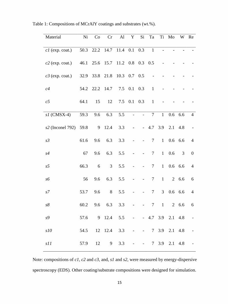
Table 1: Compositions of MCrAlY coatings and substrates (wt.%).
Material Ni Co Cr Al Y Si Ta Ti Mo W Re
c1 (exp. coat.) 50.3 22.2 14.7 11.4 0.1 0.3 1 - - - -
c2 (exp. coat.) 46.1 25.6 15.7 11.2 0.8 0.3 0.5 - - - -
c3 (exp. coat.) 32.9 33.8 21.8 10.3 0.7 0.5 - - - - -
c4 54.2 22.2 14.7 7.5 0.1 0.3 1 - - - -
c5 64.1 15 12 7.5 0.1 0.3 1 - - - -
s1 (CMSX-4) 59.3 9.6 6.3 5.5 - - 7 1 0.6 6.6 4
s2 (Inconel 792) 59.8 9 12.4 3.3 - - 4.7 3.9 2.1 4.8 -
s3 61.6 9.6 6.3 3.3 - - 7 1 0.6 6.6 4
s4 67 9.6 6.3 5.5 - - 7 1 0.6 3 0
s5 66.3 6 3 5.5 - - 7 1 0.6 6.6 4
s6 56 9.6 6.3 5.5 - - 7 1 2 6.6 6
s7 53.7 9.6 8 5.5 - - 7 3 0.6 6.6 4
s8 60.2 9.6 6.3 3.3 - - 7 1 2 6.6 6
s9 57.6 9 12.4 5.5 - - 4.7 3.9 2.1 4.8 -
s10 54.5 12 12.4 3.3 - - 7 3.9 2.1 4.8 -
s11 57.9 12 9 3.3 - - 7 3.9 2.1 4.8 -
Note: compositions of c1, c2 and c3, and, s1 and s2, were measured by energy-dispersive
spectroscopy (EDS). Other coating/substrate compositions were designed for simulation.
16
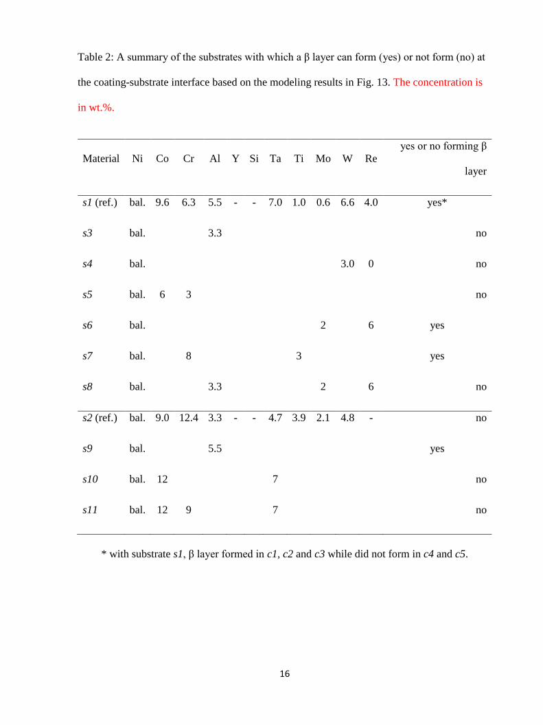
Table 2: A summary of the substrates with which a β layer can form (yes) or not form (no) at
the coating-substrate interface based on the modeling results in Fig. 13. The concentration is
in wt.%.
Material Ni Co Cr Al Y Si Ta Ti Mo W Re yes or no forming β
layer
s1 (ref.) bal. 9.6 6.3 5.5 - - 7.0 1.0 0.6 6.6 4.0 yes*
s3 bal. 3.3 no
s4 bal. 3.0 0 no
s5 bal. 6 3 no
s6 bal. 2 6 yes
s7 bal. 8 3 yes
s8 bal. 3.3 2 6 no
s2 (ref.) bal. 9.0 12.4 3.3 - - 4.7 3.9 2.1 4.8 - no
s9 bal. 5.5 yes
s10 bal. 12 7 no
s11 bal. 12 9 7 no
* with substrate s1, β layer formed in c1, c2 and c3 while did not form in c4 and c5.