SIL 2 - Gasdetectorsusa.com
69
SIL 2 IEC 61508 合格声明 Декларация λ λ
Transcript of SIL 2 - Gasdetectorsusa.com
SIL 2
IEC 61508
合格声明Декларация
λ
λ
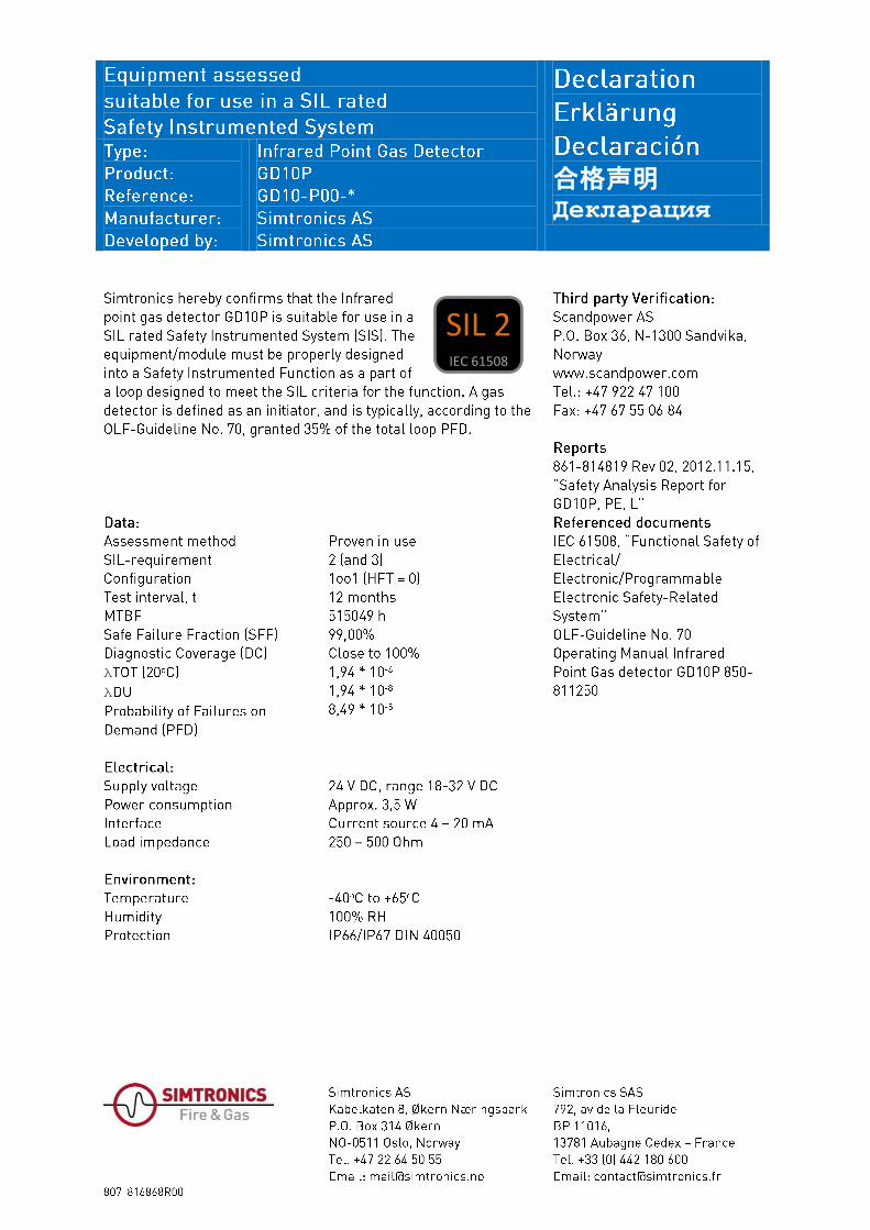
This document is the property of Simtronics ASA Dette dokumentet er Simtronics ASAs eiendom og må ikke and must not be copied, shown, or in any way be kopieres, fremvises eller på annen måte meddeles andre communicated to persons other than those requiring the enn de som trenger disse opplysningene for utførelsen av information for the execution of their duty. sine plikter.
Document No. 861-814819
Safety Analysis Report for GD10P,PE,L
Document code or file name: (Mandatory if Document No. is not used): SDM-75742 - Safety Analysis Report (SAR)
REVISION
DOC REVISION DATE CN
DESCRIPTION OF CHANGE (Alternatively, use last page for descriptions. CN N/A for non-released documents.)
Sign.
00 04.02.05 01 07.09.26 07 Updated with additional information as FMEA, reference list and MTBF number HK
DOC. REVISION PREPARED VERIFIED APPROVED
01
Name: Steinar Lind Title: Dev.Eng. Sign:
Name: Kristina Arianson Title: Consultant / Scandpower Sign:
Name: Arvid Bjerkestrand Title: R&D Manager Sign:
861-814819 Revision 01
- 1 -
P.O. Box 3, N-2027 Kjeller, Norway
www.scandpower.com Tel.: +47 64 84 44 00 Fax: +47 64 84 44 11
I. ABBREVIATIONS AND DEFINITIONS
λ SD Lambda Safe Detected λ SU Lambda Safe Undetected λ DD Lambda Dangerous Detected λ DU Lambda Dangerous Undetected λ TOT Lambda Total CCF Common Cause Failure DC Diagnostic Coverage E/E/PE Electric/Electronic/Programmable Electronic FMEA Failure Mode Effect Analysis FMECA Failure Mode Effect Criticality Analysis HWT Hardware Fault Tolerance IEC International Electrotechnical Comission IR Infrared LEL Lower Explosion Level MTBF Mean Time Between Failures MTTR Mean Time To Repair N/A Not Applicable OREDA Offshore Reliability Data PbSe Lead selenide PCS Production Control System PFD Probability of Failure on Demand PLC Programmable Logic Controller PSF Probability of Systematic Failures SAR Safety Analysis Report SFF Safe Failure Fraction SIL Safety Integrity Level SIS Safety Instrumented System SRS Safety Requirement Specification Definitions are based on the definitions in IEC 61508 - Part 4.
861-814819 Revision 01
- 2 -
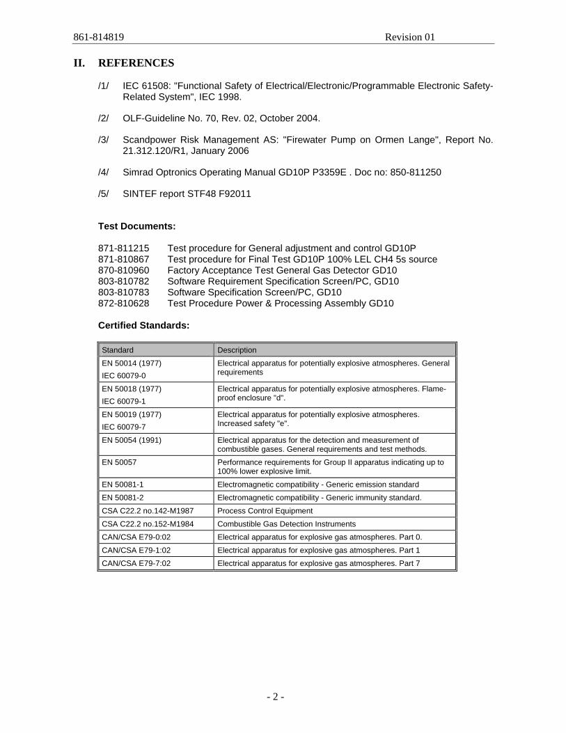
II. REFERENCES
/1/ IEC 61508: "Functional Safety of Electrical/Electronic/Programmable Electronic Safety-
Related System", IEC 1998.
/2/ OLF-Guideline No. 70, Rev. 02, October 2004.
/3/ Scandpower Risk Management AS: "Firewater Pump on Ormen Lange", Report No. 21.312.120/R1, January 2006
/4/ Simrad Optronics Operating Manual GD10P P3359E . Doc no: 850-811250
/5/ SINTEF report STF48 F92011
Test Documents: 871-811215 Test procedure for General adjustment and control GD10P 871-810867 Test procedure for Final Test GD10P 100% LEL CH4 5s source 870-810960 Factory Acceptance Test General Gas Detector GD10 803-810782 Software Requirement Specification Screen/PC, GD10 803-810783 Software Specification Screen/PC, GD10 872-810628 Test Procedure Power & Processing Assembly GD10 Certified Standards: Standard Description
EN 50014 (1977) IEC 60079-0
Electrical apparatus for potentially explosive atmospheres. General requirements
EN 50018 (1977) IEC 60079-1
Electrical apparatus for potentially explosive atmospheres. Flame-proof enclosure "d".
EN 50019 (1977) IEC 60079-7
Electrical apparatus for potentially explosive atmospheres. Increased safety "e".
EN 50054 (1991) Electrical apparatus for the detection and measurement of combustible gases. General requirements and test methods.
EN 50057 Performance requirements for Group II apparatus indicating up to 100% lower explosive limit.
EN 50081-1 Electromagnetic compatibility - Generic emission standard
EN 50081-2 Electromagnetic compatibility - Generic immunity standard.
CSA C22.2 no.142-M1987 Process Control Equipment
CSA C22.2 no.152-M1984 Combustible Gas Detection Instruments
CAN/CSA E79-0:02 Electrical apparatus for explosive gas atmospheres. Part 0.
CAN/CSA E79-1:02 Electrical apparatus for explosive gas atmospheres. Part 1
CAN/CSA E79-7:02 Electrical apparatus for explosive gas atmospheres. Part 7
861-814819 Revision 01
- 3 -
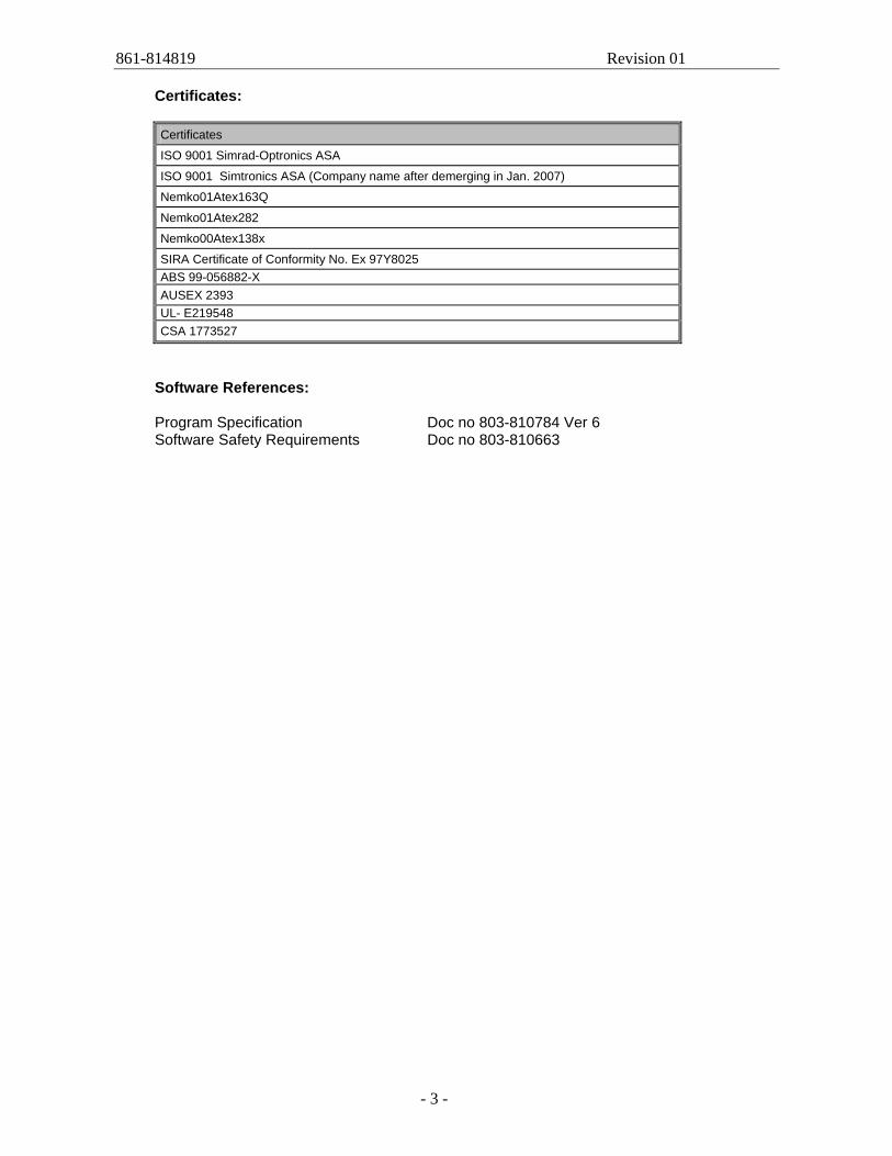
Certificates: Certificates
ISO 9001 Simrad-Optronics ASA
ISO 9001 Simtronics ASA (Company name after demerging in Jan. 2007)
Nemko01Atex163Q
Nemko01Atex282
Nemko00Atex138x
SIRA Certificate of Conformity No. Ex 97Y8025 ABS 99-056882-X AUSEX 2393 UL- E219548 CSA 1773527
Software References: Program Specification Doc no 803-810784 Ver 6 Software Safety Requirements Doc no 803-810663
861-814819 Revision 01
- 4 -
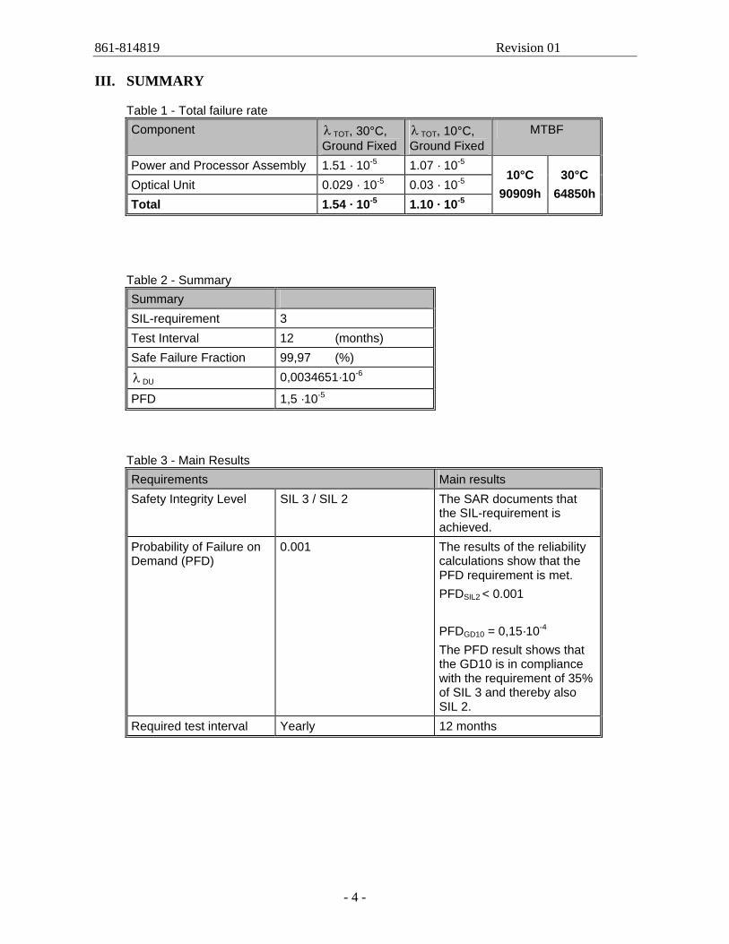
III. SUMMARY
Table 1 - Total failure rate Component λ TOT, 30°C,
Ground Fixed λ TOT, 10°C, Ground Fixed
MTBF
Power and Processor Assembly 1.51 · 10-5 1.07 · 10-5 Optical Unit 0.029 · 10-5 0.03 · 10-5 Total 1.54 · 10-5 1.10 · 10-5
10°C 90909h
30°C 64850h
Table 2 - Summary Summary SIL-requirement 3 Test Interval 12 (months) Safe Failure Fraction 99,97 (%)
λ DU 0,0034651·10-6
PFD 1,5 ·10-5
Table 3 - Main Results Requirements Main results Safety Integrity Level SIL 3 / SIL 2 The SAR documents that
the SIL-requirement is achieved.
Probability of Failure on Demand (PFD)
0.001 The results of the reliability calculations show that the PFD requirement is met. PFDSIL2 < 0.001 PFDGD10 = 0,15·10-4 The PFD result shows that the GD10 is in compliance with the requirement of 35% of SIL 3 and thereby also SIL 2.
Required test interval Yearly 12 months
861-814819 Revision 01
- 5 -
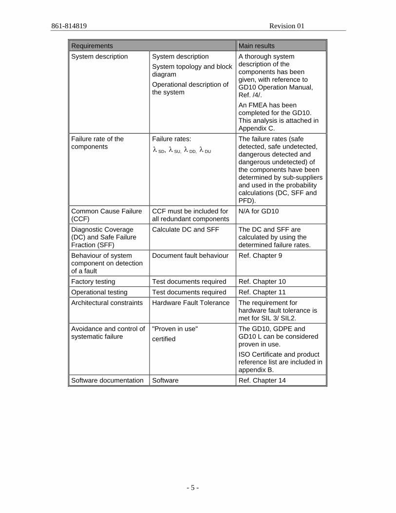
Requirements Main results System description
System description System topology and block diagram Operational description of the system
A thorough system description of the components has been given, with reference to GD10 Operation Manual, Ref. /4/. An FMEA has been completed for the GD10. This analysis is attached in Appendix C.
Failure rate of the components
Failure rates: λ SD, λ SU, λ DD, λ DU
The failure rates (safe detected, safe undetected, dangerous detected and dangerous undetected) of the components have been determined by sub-suppliers and used in the probability calculations (DC, SFF and PFD).
Common Cause Failure (CCF)
CCF must be included for all redundant components
N/A for GD10
Diagnostic Coverage (DC) and Safe Failure Fraction (SFF)
Calculate DC and SFF The DC and SFF are calculated by using the determined failure rates.
Behaviour of system component on detection of a fault
Document fault behaviour Ref. Chapter 9
Factory testing Test documents required Ref. Chapter 10 Operational testing Test documents required Ref. Chapter 11 Architectural constraints Hardware Fault Tolerance The requirement for
hardware fault tolerance is met for SIL 3/ SIL2.
Avoidance and control of systematic failure
"Proven in use" certified
The GD10, GDPE and GD10 L can be considered proven in use. ISO Certificate and product reference list are included in appendix B.
Software documentation Software Ref. Chapter 14
861-814819 Revision 01
- 6 -
TABLE OF CONTENTS
I. ABBREVIATIONS AND DEFINITIONS II. REFERENCES III. SUMMARY
1. INTRODUCTION 1.1 General 1.2 Scope of Work
2. SYSTEM DESCRIPTION 2.1 General 2.2 Construction 2.3 Gas data
3. SYSTEM TOPOLOGY AND BLOCK DIAGRAM 3.1 Block Diagram
4. OPERATIONAL DESCRIPTION OF THE SYSTEM 4.1 Installation
4.1.1 Mounting 4.1.2 Electrical Connections
4.2 Start-up procedure
5. ASSUMPTIONS 5.1 Restrictions
6. FAILURE RATE OF THE COMPONENTS Failure Data from Repair Statistics Dangerous Undetected Failures
7. COMMON CAUSE FAILURES
8. DIAGNOSTIC COVERAGE & SAFE FAILURE FRACTION
9. BEHAVIOUR OF SYSTEMS/COMPONENTS ON DETECTION OF A FAULT
10. FACTORY TESTING
11. OPERATIONAL TESTING
12. ARCHITECTURAL CONSTRAINTS 12.1 General
13. AVOIDANCE AND CONTROL OF SYSTEMATIC FAILURES
14. SOFTWARE DOCUMENTATION
15. RESULTS
Appendix A: Failure Rate Data Appendix B: An extract of the reference list and certificates Appendix C: FMEA for GD10
861-814819 Revision 01
- 7 -
1. INTRODUCTION
1.1 General
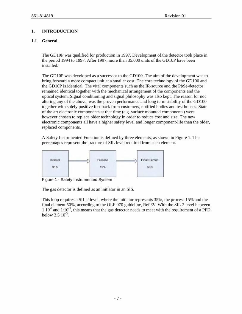
The GD10P was qualified for production in 1997. Development of the detector took place in the period 1994 to 1997. After 1997, more than 35.000 units of the GD10P have been installed. The GD10P was developed as a successor to the GD100. The aim of the development was to bring forward a more compact unit at a smaller cost. The core technology of the GD100 and the GD10P is identical. The vital components such as the IR-source and the PbSe-detector remained identical together with the mechanical arrangement of the components and the optical system. Signal conditioning and signal philosophy was also kept. The reason for not altering any of the above, was the proven performance and long term stability of the GD100 together with solely positive feedback from customers, notified bodies and test houses. State of the art electronic components at that time (e.g. surface mounted components) were however chosen to replace older technology in order to reduce cost and size. The new electronic components all have a higher safety level and longer component-life than the older, replaced components. A Safety Instrumented Function is defined by three elements, as shown in Figure 1. The percentages represent the fracture of SIL level required from each element.
Figure 1 - Safety Instrumented System The gas detector is defined as an initiator in an SIS. This loop requires a SIL 2 level, where the initiator represents 35%, the process 15% and the final element 50%, according to the OLF 070 guideline, Ref /2/. With the SIL 2 level between 1·10-2 and 1·10-3, this means that the gas detector needs to meet with the requirement of a PFD below 3.5·10-3.
861-814819 Revision 01
- 8 -
1.2 Scope of Work
The SAR is part of the vendor documentation from the engineering and construction phase and contains information regarding how Simtronics, as a vendor, has implemented the requirements set by IEC 61508/61511, the OLF Guideline 070 and the SRS. - IEC 61508-2 clause 7.4.7.3 lists information that shall be available for each safety-
related subsystem and hence documented in the SAR - IEC 61511-1 clause 11.9.2 lists information that shall be taken into account when
calculating the PFD due to hardware failures and hence documented in the SAR - The SAR layout suggested in the OLF Guideline 070, Chapter E.3 has been used.This
SAR is based on the requirements to SAR given in the OLF Guideline, Ref. /2/.
861-814819 Revision 01
- 9 -
2. SYSTEM DESCRIPTION
The information in this chapter refers to the GD10 Operating Manual, chapters 1 and 2, Ref. /4/, if nothing else stated.
2.1 General
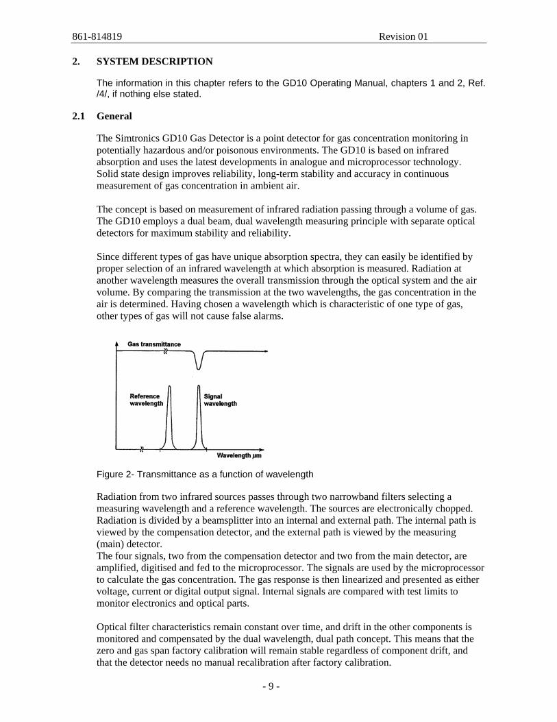
The Simtronics GD10 Gas Detector is a point detector for gas concentration monitoring in potentially hazardous and/or poisonous environments. The GD10 is based on infrared absorption and uses the latest developments in analogue and microprocessor technology. Solid state design improves reliability, long-term stability and accuracy in continuous measurement of gas concentration in ambient air. The concept is based on measurement of infrared radiation passing through a volume of gas. The GD10 employs a dual beam, dual wavelength measuring principle with separate optical detectors for maximum stability and reliability. Since different types of gas have unique absorption spectra, they can easily be identified by proper selection of an infrared wavelength at which absorption is measured. Radiation at another wavelength measures the overall transmission through the optical system and the air volume. By comparing the transmission at the two wavelengths, the gas concentration in the air is determined. Having chosen a wavelength which is characteristic of one type of gas, other types of gas will not cause false alarms.
Figure 2- Transmittance as a function of wavelength Radiation from two infrared sources passes through two narrowband filters selecting a measuring wavelength and a reference wavelength. The sources are electronically chopped. Radiation is divided by a beamsplitter into an internal and external path. The internal path is viewed by the compensation detector, and the external path is viewed by the measuring (main) detector. The four signals, two from the compensation detector and two from the main detector, are amplified, digitised and fed to the microprocessor. The signals are used by the microprocessor to calculate the gas concentration. The gas response is then linearized and presented as either voltage, current or digital output signal. Internal signals are compared with test limits to monitor electronics and optical parts. Optical filter characteristics remain constant over time, and drift in the other components is monitored and compensated by the dual wavelength, dual path concept. This means that the zero and gas span factory calibration will remain stable regardless of component drift, and that the detector needs no manual recalibration after factory calibration.
861-814819 Revision 01
- 10 -
2.2 Construction
A complete GD10 Gas Detector consists of the following: - An external gas measuring path where gas is measured by means of IR radiation. A
weather protection enclosure is mounted around the measuring path to protect the optical surfaces from rain and dust.
- An optoelectronic unit, which generates IR radiation to the gas measuring path, measures the reflected IR radiation from the gas measuring path and calculates the gas concentration. This unit is enclosed by an EExd certified housing.
- A terminal compartment with cable entry and mini-terminals for electrical connection. The compartment is protected by a cover and is EExe certified.
2.3 Gas data
The GD10 standard version is factory calibrated and linearized with methane gas in the 0-100% LEL range. Calibration/linearization to other gases or concentrations can also be done. Accurate measurements can only be achieved by having the detector calibrated for the gas it is intended to measure. Gases such as ethane, propane and butane are also detected by the GD10. A GD10 calibrated for methane has a higher sensitivity to these gases than to methane. This means that explosion danger from other HC-gases will always be detected by the GD10.
861-814819 Revision 01
- 11 -
3. SYSTEM TOPOLOGY AND BLOCK DIAGRAM
3.1 Block Diagram
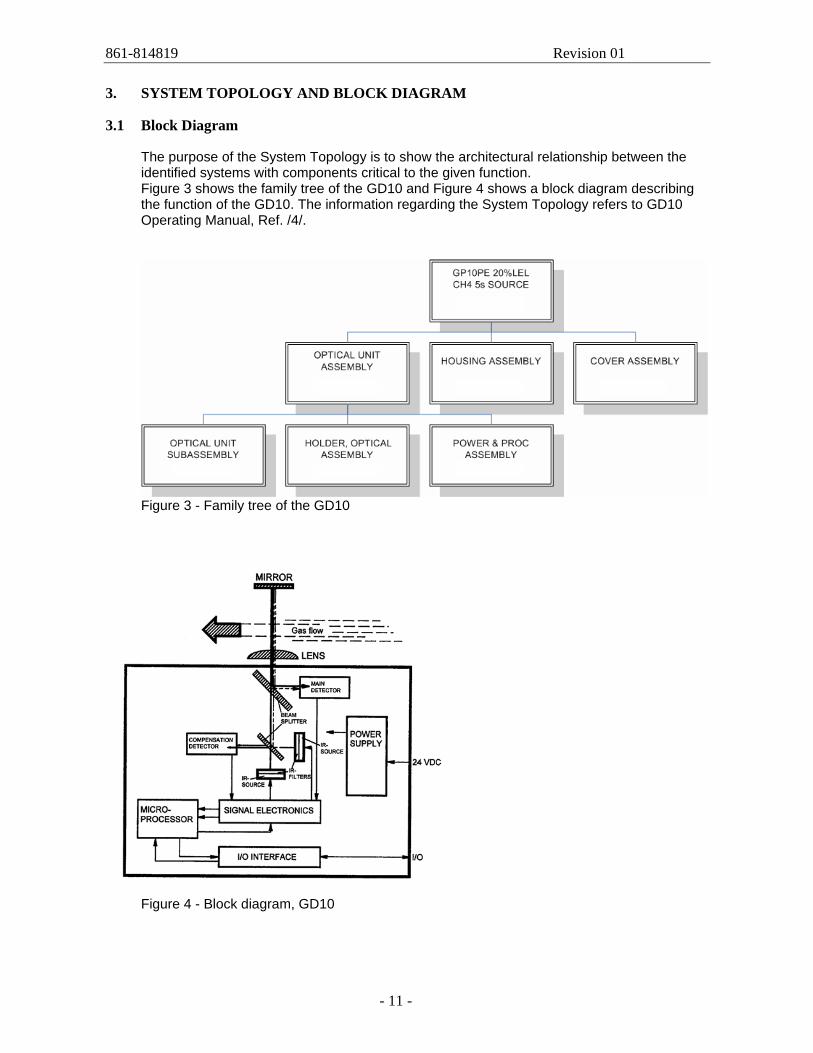
The purpose of the System Topology is to show the architectural relationship between the identified systems with components critical to the given function. Figure 3 shows the family tree of the GD10 and Figure 4 shows a block diagram describing the function of the GD10. The information regarding the System Topology refers to GD10 Operating Manual, Ref. /4/.
Figure 3 - Family tree of the GD10
Figure 4 - Block diagram, GD10
861-814819 Revision 01
- 12 -
4. OPERATIONAL DESCRIPTION OF THE SYSTEM
4.1 Installation
The information in this chapter refers to the GD10 Operating Manual, Ref. /4/, chapters 3, 4 and 5 if nothing else stated.
4.1.1 Mounting
The location of each detector should preferably be determined at the system design stage. Choice of mounting area: 1. The detector should be mounted where the gas leakage is most likely to occur. To
detect methane, which is lighter than air, inside an enclosed area the detector should be mounted high in the area to be protected or immediately above potential leaking sites.
2. To detect gases heavier than air, e.g. propane, the detector should be mounted below the potential leaking site.
3. The detector should be mounted in a place where maintenance, i.e cleaning of the optics, is easily performed.
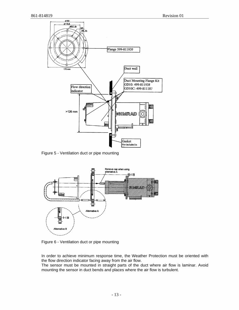
4. The detector may be mounted in areas where no oxygen is present. 5. The detector may be mounted in areas with strong airflow. 6. The detector should NOT be mounted where it could be exposed to water drenching. If installed in a ventilation duct or pipe, the mounting arrangement and accessories shown in Figure 5 and Figure 6 should be used.
861-814819 Revision 01
- 13 -
Figure 5 - Ventilation duct or pipe mounting
Figure 6 - Ventilation duct or pipe mounting In order to achieve minimum response time, the Weather Protection must be oriented with the flow direction indicator facing away from the air flow. The sensor must be mounted in straight parts of the duct where air flow is laminar. Avoid mounting the sensor in duct bends and places where the air flow is turbulent.
861-814819 Revision 01
- 14 -
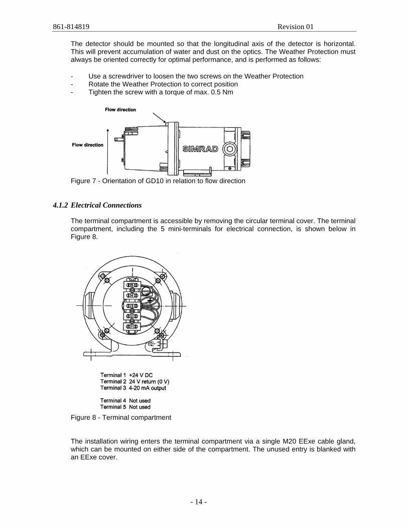
The detector should be mounted so that the longitudinal axis of the detector is horizontal. This will prevent accumulation of water and dust on the optics. The Weather Protection must always be oriented correctly for optimal performance, and is performed as follows: - Use a screwdriver to loosen the two screws on the Weather Protection - Rotate the Weather Protection to correct position - Tighten the screw with a torque of max. 0.5 Nm
Figure 7 - Orientation of GD10 in relation to flow direction
4.1.2 Electrical Connections
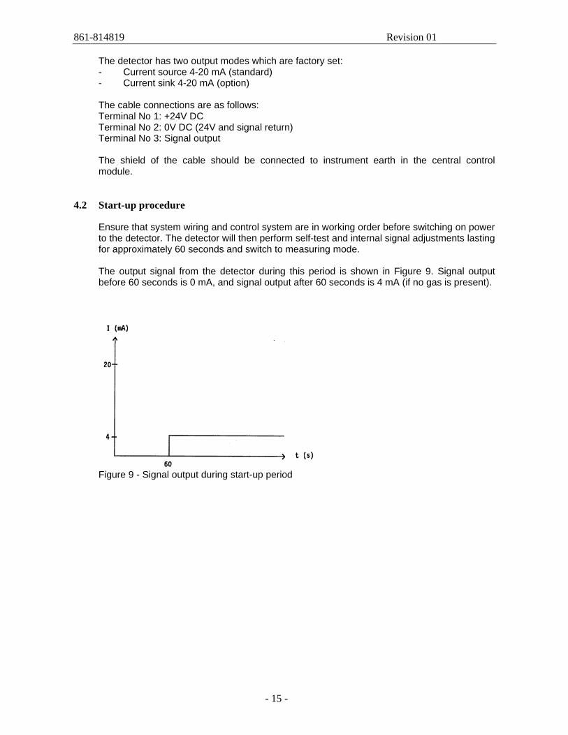
The terminal compartment is accessible by removing the circular terminal cover. The terminal compartment, including the 5 mini-terminals for electrical connection, is shown below in Figure 8.
Figure 8 - Terminal compartment The installation wiring enters the terminal compartment via a single M20 EExe cable gland, which can be mounted on either side of the compartment. The unused entry is blanked with an EExe cover.
861-814819 Revision 01
- 15 -
The detector has two output modes which are factory set: - Current source 4-20 mA (standard) - Current sink 4-20 mA (option)
The cable connections are as follows: Terminal No 1: +24V DC Terminal No 2: 0V DC (24V and signal return) Terminal No 3: Signal output The shield of the cable should be connected to instrument earth in the central control module.
4.2 Start-up procedure
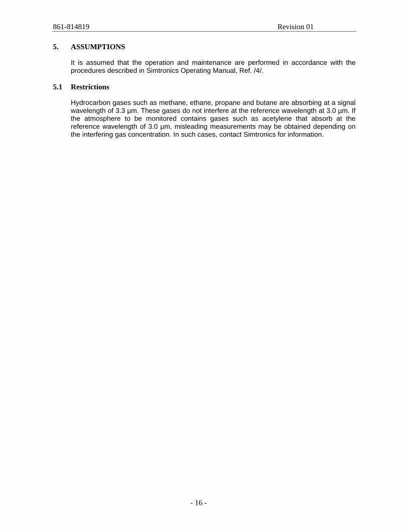
Ensure that system wiring and control system are in working order before switching on power to the detector. The detector will then perform self-test and internal signal adjustments lasting for approximately 60 seconds and switch to measuring mode. The output signal from the detector during this period is shown in Figure 9. Signal output before 60 seconds is 0 mA, and signal output after 60 seconds is 4 mA (if no gas is present).
Figure 9 - Signal output during start-up period
861-814819 Revision 01
- 16 -
5. ASSUMPTIONS
It is assumed that the operation and maintenance are performed in accordance with the procedures described in Simtronics Operating Manual, Ref. /4/.
5.1 Restrictions
Hydrocarbon gases such as methane, ethane, propane and butane are absorbing at a signal wavelength of 3.3 µm. These gases do not interfere at the reference wavelength at 3.0 µm. If the atmosphere to be monitored contains gases such as acetylene that absorb at the reference wavelength of 3.0 µm, misleading measurements may be obtained depending on the interfering gas concentration. In such cases, contact Simtronics for information.
861-814819 Revision 01
- 17 -
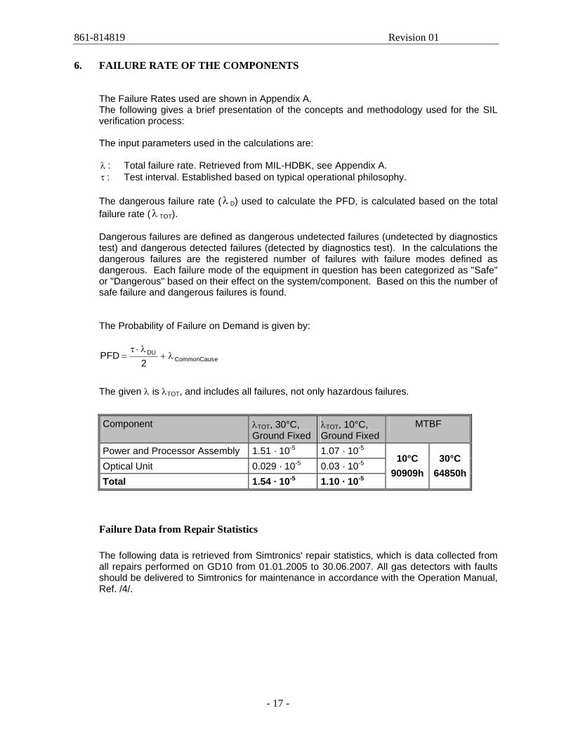
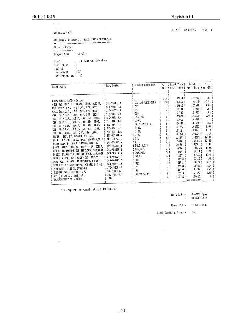
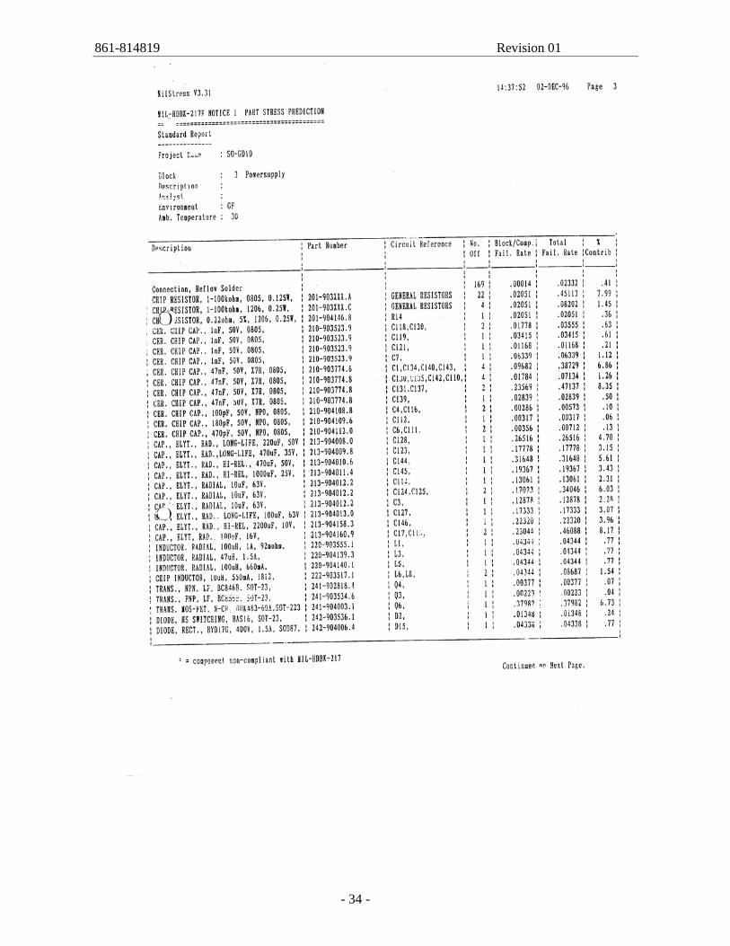
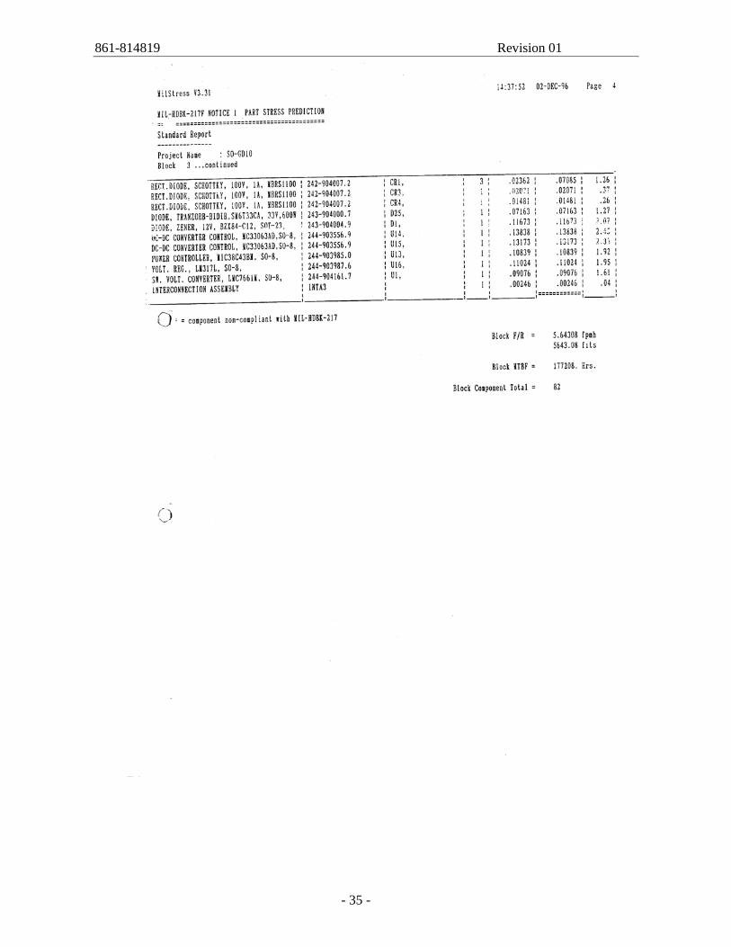
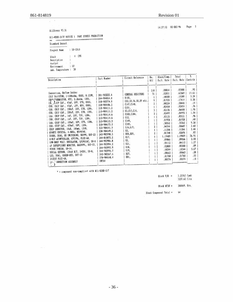
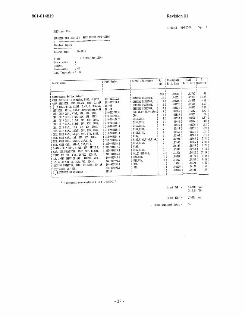
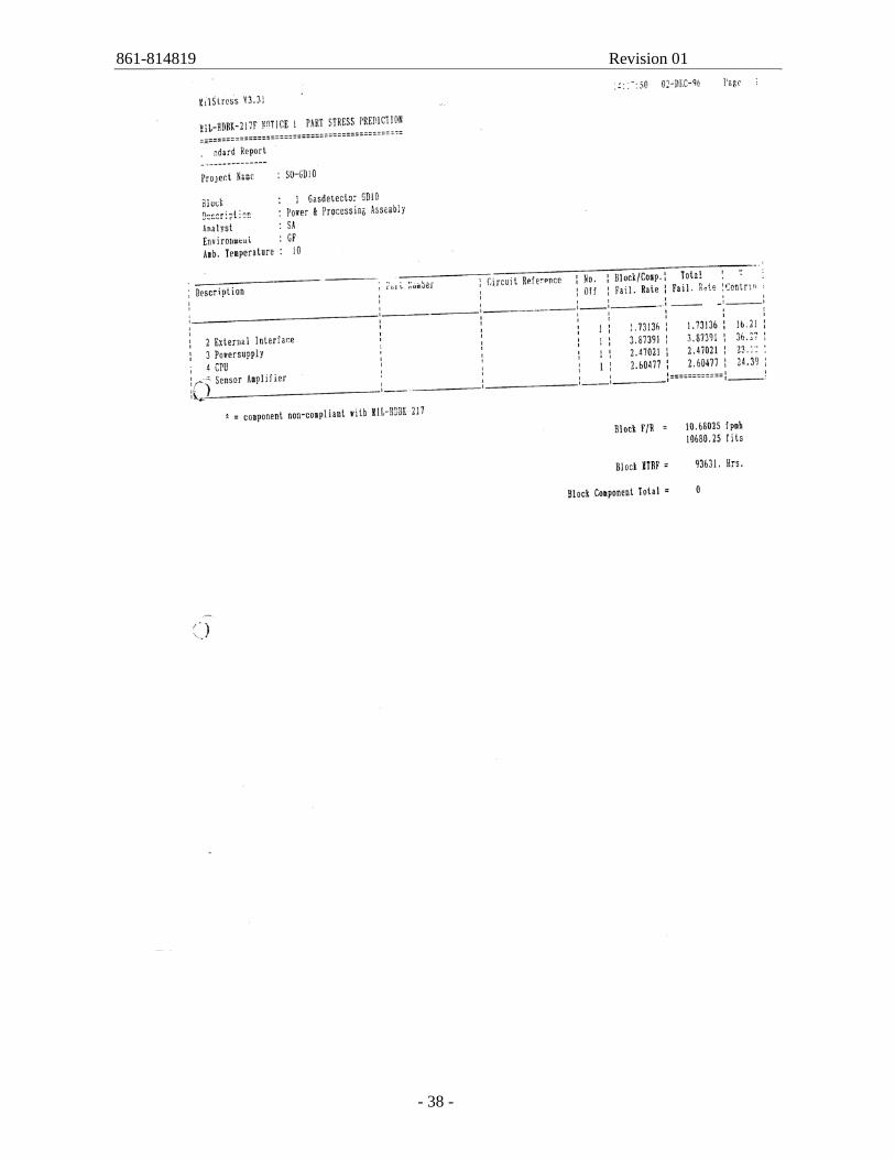
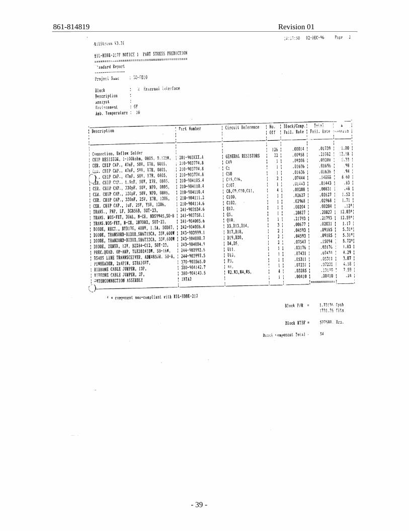
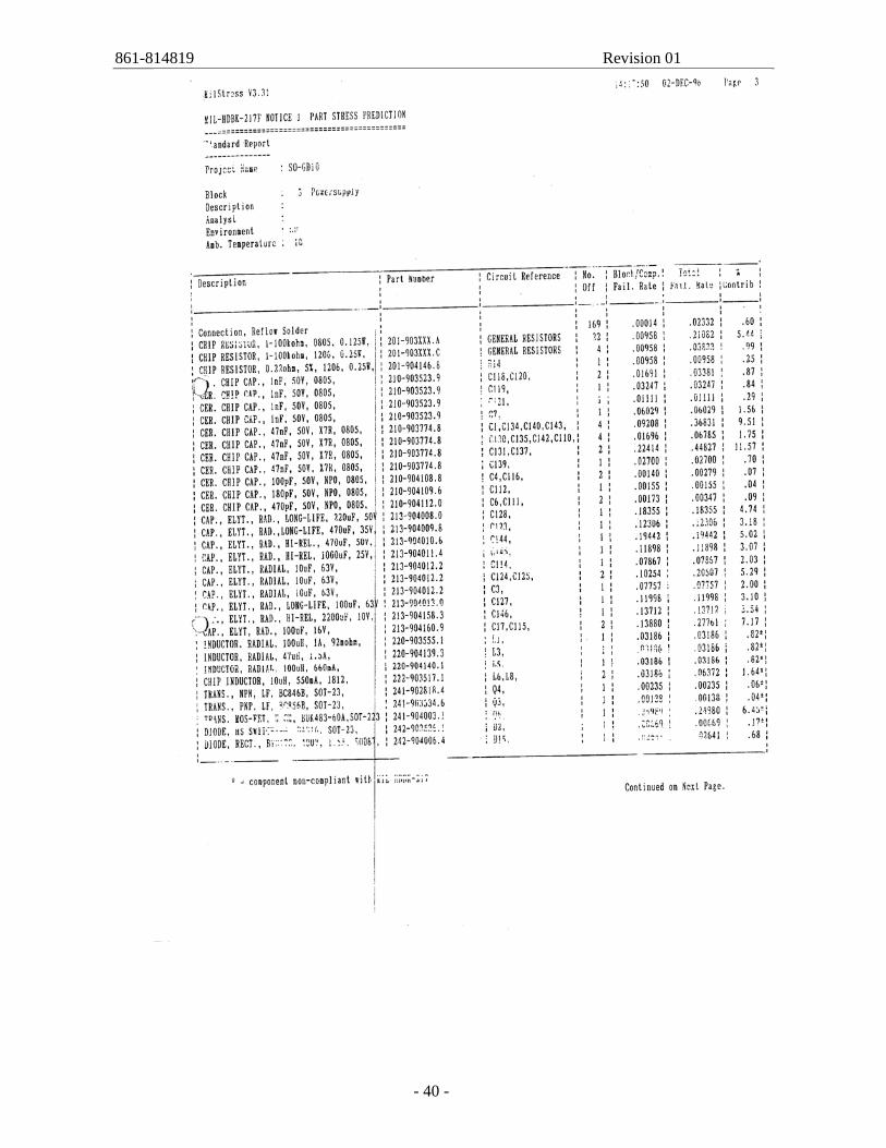
6. FAILURE RATE OF THE COMPONENTS
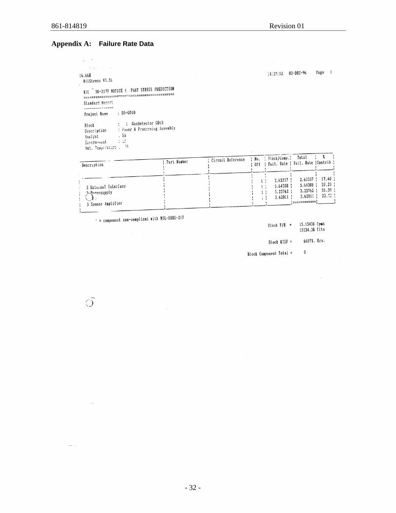
The Failure Rates used are shown in Appendix A. The following gives a brief presentation of the concepts and methodology used for the SIL verification process: The input parameters used in the calculations are: λ : Total failure rate. Retrieved from MIL-HDBK, see Appendix A. τ : Test interval. Established based on typical operational philosophy. The dangerous failure rate (λ D) used to calculate the PFD, is calculated based on the total failure rate (λ TOT). Dangerous failures are defined as dangerous undetected failures (undetected by diagnostics test) and dangerous detected failures (detected by diagnostics test). In the calculations the dangerous failures are the registered number of failures with failure modes defined as dangerous. Each failure mode of the equipment in question has been categorized as "Safe" or "Dangerous" based on their effect on the system/component. Based on this the number of safe failure and dangerous failures is found. The Probability of Failure on Demand is given by:
eCommonCausDU
2PFD λ+
λ⋅τ=
The given λ is λTOT, and includes all failures, not only hazardous failures.
Component λTOT, 30°C, Ground Fixed
λTOT, 10°C, Ground Fixed
MTBF
Power and Processor Assembly 1.51 · 10-5 1.07 · 10-5 Optical Unit 0.029 · 10-5 0.03 · 10-5 Total 1.54 · 10-5 1.10 · 10-5
10°C 90909h
30°C 64850h
Failure Data from Repair Statistics
The following data is retrieved from Simtronics' repair statistics, which is data collected from all repairs performed on GD10 from 01.01.2005 to 30.06.2007. All gas detectors with faults should be delivered to Simtronics for maintenance in accordance with the Operation Manual, Ref. /4/.
861-814819 Revision 01
- 18 -
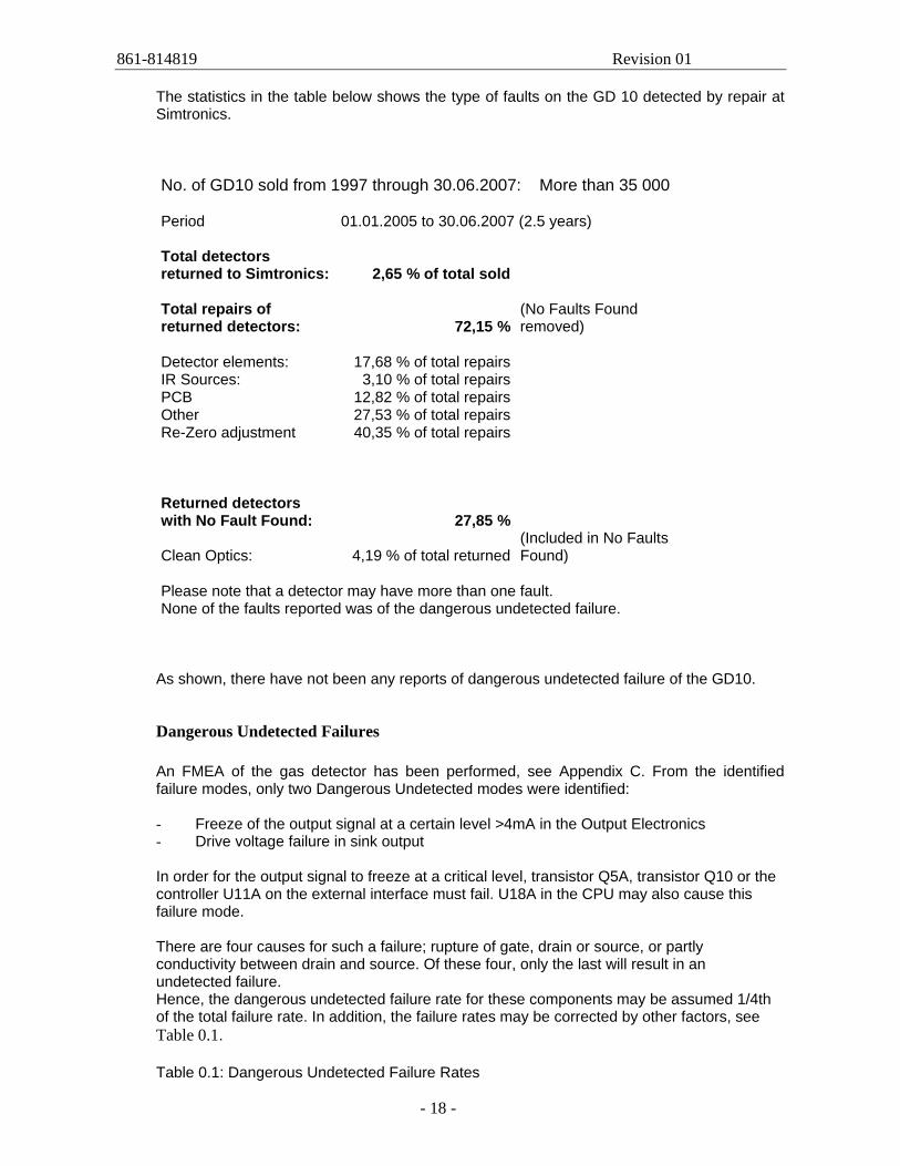
The statistics in the table below shows the type of faults on the GD 10 detected by repair at Simtronics. No. of GD10 sold from 1997 through 30.06.2007: More than 35 000 Period 01.01.2005 to 30.06.2007 (2.5 years) Total detectors returned to Simtronics: 2,65 % of total sold Total repairs of returned detectors: 72,15 %
(No Faults Found removed)
Detector elements: 17,68 % of total repairs IR Sources: 3,10 % of total repairs PCB 12,82 % of total repairs Other 27,53 % of total repairs Re-Zero adjustment 40,35 % of total repairs Returned detectors with No Fault Found: 27,85 %
Clean Optics: 4,19 % of total returned(Included in No Faults Found)
Please note that a detector may have more than one fault. None of the faults reported was of the dangerous undetected failure.
As shown, there have not been any reports of dangerous undetected failure of the GD10.
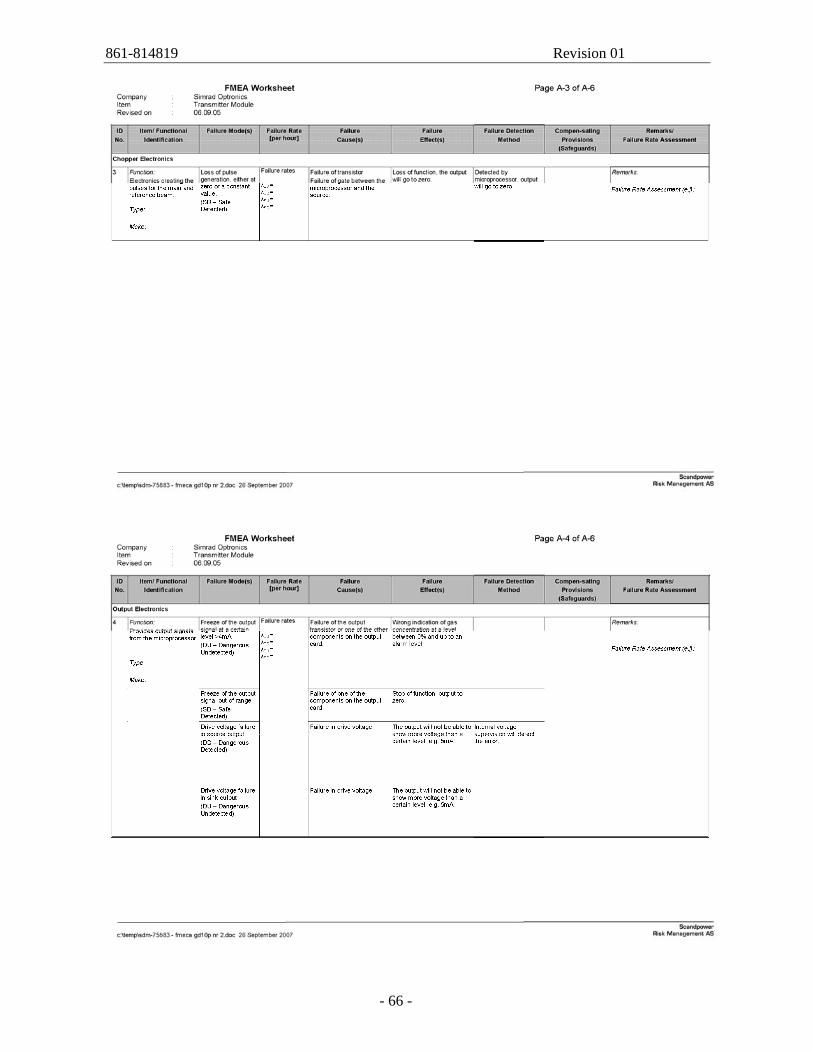
Dangerous Undetected Failures An FMEA of the gas detector has been performed, see Appendix C. From the identified failure modes, only two Dangerous Undetected modes were identified: - Freeze of the output signal at a certain level >4mA in the Output Electronics - Drive voltage failure in sink output In order for the output signal to freeze at a critical level, transistor Q5A, transistor Q10 or the controller U11A on the external interface must fail. U18A in the CPU may also cause this failure mode.
There are four causes for such a failure; rupture of gate, drain or source, or partly conductivity between drain and source. Of these four, only the last will result in an undetected failure. Hence, the dangerous undetected failure rate for these components may be assumed 1/4th of the total failure rate. In addition, the failure rates may be corrected by other factors, see Table 0.1.
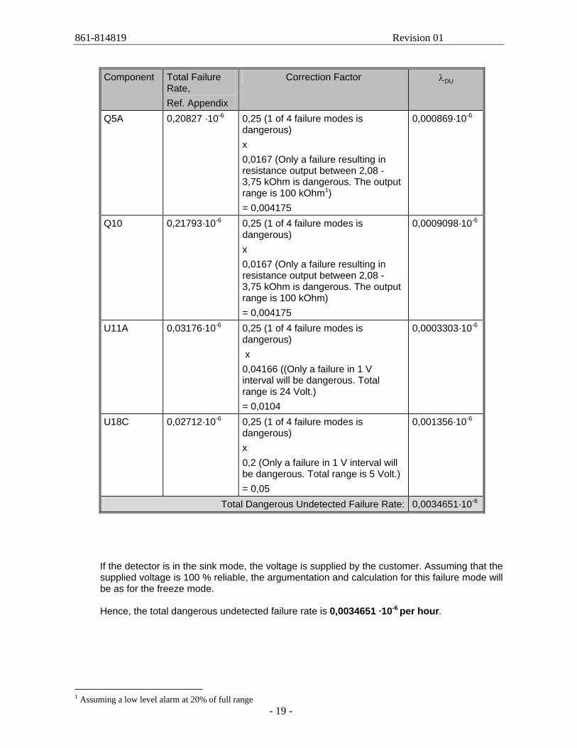
Table 0.1: Dangerous Undetected Failure Rates
861-814819 Revision 01
- 19 -
Component Total Failure
Rate, Ref. Appendix
Correction Factor DUλ
Q5A 0,20827 ·10-6
0,25 (1 of 4 failure modes is dangerous) x 0,0167 (Only a failure resulting in resistance output between 2,08 - 3,75 kOhm is dangerous. The output range is 100 kOhm1) = 0,004175
0,000869·10-6
Q10 0,21793·10-6 0,25 (1 of 4 failure modes is dangerous) x 0,0167 (Only a failure resulting in resistance output between 2,08 - 3,75 kOhm is dangerous. The output range is 100 kOhm) = 0,004175
0,0009098·10-6
U11A 0,03176·10-6 0,25 (1 of 4 failure modes is dangerous) x 0,04166 ((Only a failure in 1 V interval will be dangerous. Total range is 24 Volt.) = 0,0104
0,0003303·10-6
U18C 0,02712·10-6 0,25 (1 of 4 failure modes is dangerous) x 0,2 (Only a failure in 1 V interval will be dangerous. Total range is 5 Volt.) = 0,05
0,001356·10-6
Total Dangerous Undetected Failure Rate: 0,0034651·10-6
If the detector is in the sink mode, the voltage is supplied by the customer. Assuming that the supplied voltage is 100 % reliable, the argumentation and calculation for this failure mode will be as for the freeze mode. Hence, the total dangerous undetected failure rate is 0,0034651 ·10-6 per hour.
1 Assuming a low level alarm at 20% of full range
861-814819 Revision 01
- 20 -
7. COMMON CAUSE FAILURES
There are not identified any common cause failures for the GD10, GDPE or GD10L.
861-814819 Revision 01
- 21 -
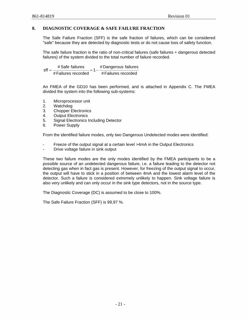
8. DIAGNOSTIC COVERAGE & SAFE FAILURE FRACTION
The Safe Failure Fraction (SFF) is the safe fraction of failures, which can be considered "safe" because they are detected by diagnostic tests or do not cause loss of safety function.
The safe failure fraction is the ratio of non-critical failures (safe failures + dangerous detected failures) of the system divided to the total number of failure recorded.
recordedFailures#failuresDangerous#
1recordedFailures#
failuresSafe#sff −==
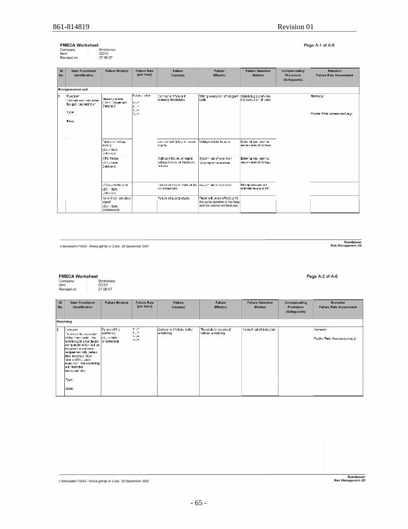
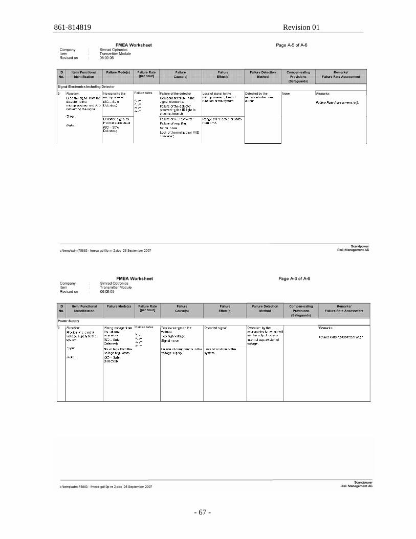
An FMEA of the GD10 has been performed, and is attached in Appendix C. The FMEA divided the system into the following sub-systems: 1. Microprocessor unit 2. Watchdog 3. Chopper Electronics 4. Output Electronics 5. Signal Electronics Including Detector 6. Power Supply
From the identified failure modes, only two Dangerous Undetected modes were identified: - Freeze of the output signal at a certain level >4mA in the Output Electronics - Drive voltage failure in sink output These two failure modes are the only modes identified by the FMEA participants to be a possible source of an undetected dangerous failure, i.e. a failure leading to the detector not detecting gas when in fact gas is present. However, for freezing of the output signal to occur, the output will have to stick in a position of between 4mA and the lowest alarm level of the detector. Such a failure is considered extremely unlikely to happen. Sink voltage failure is also very unlikely and can only occur in the sink type detectors, not in the source type. The Diagnostic Coverage (DC) is assumed to be close to 100%. The Safe Failure Fraction (SFF) is 99,97 %.
861-814819 Revision 01
- 22 -
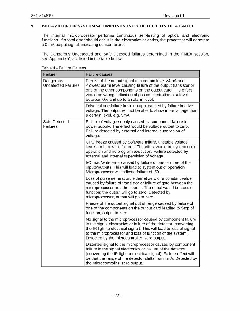
9. BEHAVIOUR OF SYSTEMS/COMPONENTS ON DETECTION OF A FAULT
The internal microprocessor performs continuous self-testing of optical and electronic functions. If a fatal error should occur in the electronics or optics, the processor will generate a 0 mA output signal, indicating sensor failure. The Dangerous Undetected and Safe Detected failures determined in the FMEA session, see Appendix Y, are listed in the table below. Table 4 - Failure Causes Failure Failure causes
Freeze of the output signal at a certain level >4mA and <lowest alarm level causing failure of the output transistor or one of the other components on the output card. The effect would be wrong indication of gas concentration at a level between 0% and up to an alarm level.
Dangerous Undetected Failures
Drive voltage failure in sink output caused by failure in drive voltage. The output will not be able to show more voltage than a certain level, e.g. 5mA. Failure of voltage supply caused by component failure in power supply. The effect would be voltage output to zero. Failure detected by external and internal supervision of voltage. CPU freeze caused by Software failure, unstable voltage levels, or hardware failures. The effect would be system out of operation and no program execution. Failure detected by external and internal supervision of voltage. I/O read/write error caused by failure of one or more of the inputs/outputs. This will lead to system out of operation. Microprocessor will indicate failure of I/O. Loss of pulse generation, either at zero or a constant value caused by failure of transistor or failure of gate between the microprocessor and the source. The effect would be Loss of function; the output will go to zero. Detected by microprocessor, output will go to zero. Freeze of the output signal out of range caused by failure of one of the components on the output card leading to Stop of function, output to zero. No signal to the microprocessor caused by component failure in the signal electronics or failure of the detector (converting the IR light to electrical signal). This will lead to loss of signal to the microprocessor and loss of function of the system. Detected by the microcontroller, zero output.
Safe Detected Failures
Distorted signal to the microprocessor caused by component failure in the signal electronics or failure of the detector (converting the IR light to electrical signal). Failure effect will be that the range of the detector shifts from 4mA. Detected by the microcontroller, zero output.
861-814819 Revision 01
- 23 -
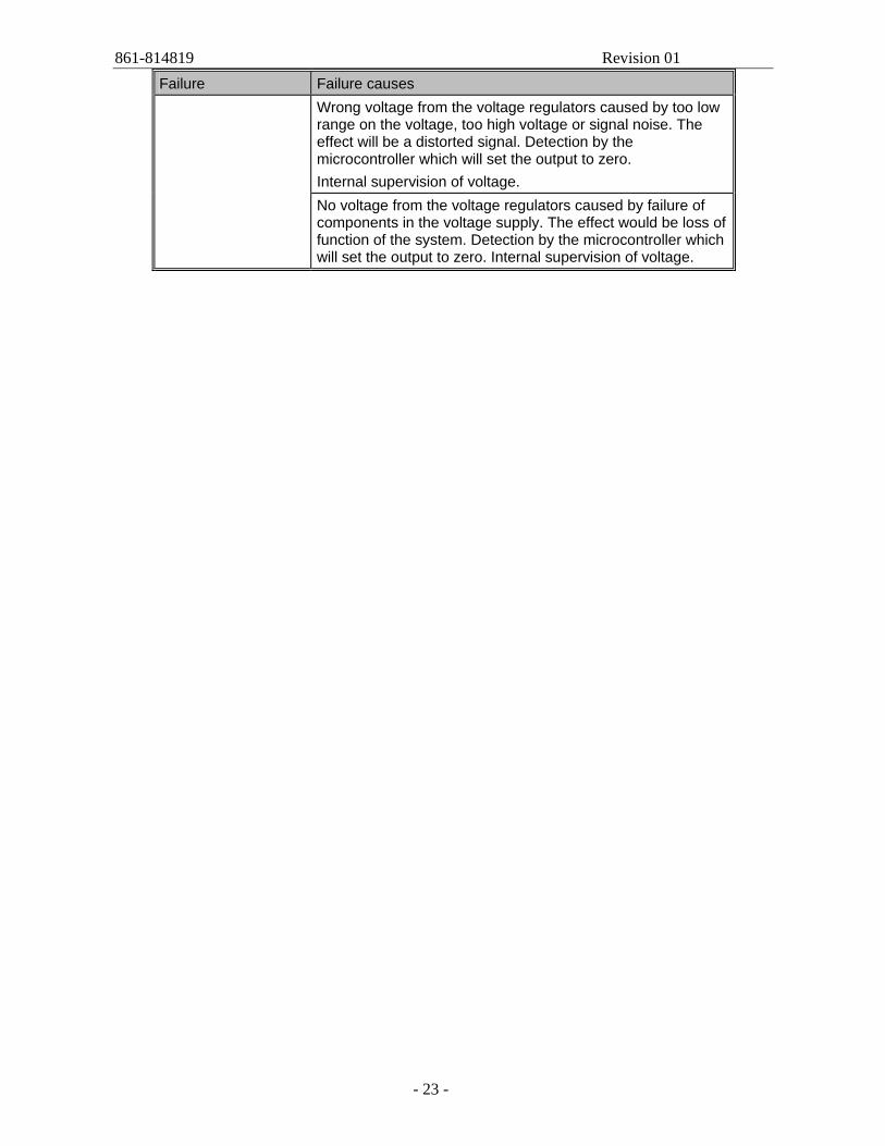
Failure Failure causes Wrong voltage from the voltage regulators caused by too low range on the voltage, too high voltage or signal noise. The effect will be a distorted signal. Detection by the microcontroller which will set the output to zero. Internal supervision of voltage. No voltage from the voltage regulators caused by failure of components in the voltage supply. The effect would be loss of function of the system. Detection by the microcontroller which will set the output to zero. Internal supervision of voltage.
861-814819 Revision 01
- 24 -
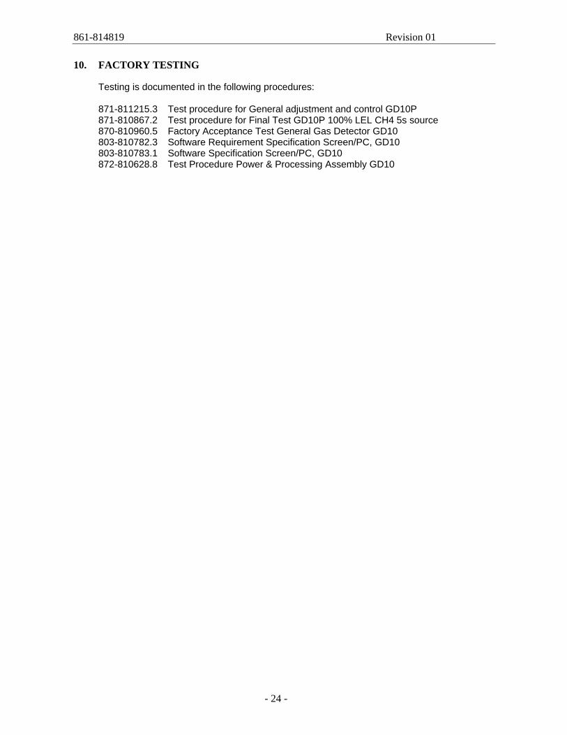
10. FACTORY TESTING
Testing is documented in the following procedures: 871-811215.3 Test procedure for General adjustment and control GD10P 871-810867.2 Test procedure for Final Test GD10P 100% LEL CH4 5s source 870-810960.5 Factory Acceptance Test General Gas Detector GD10 803-810782.3 Software Requirement Specification Screen/PC, GD10 803-810783.1 Software Specification Screen/PC, GD10 872-810628.8 Test Procedure Power & Processing Assembly GD10
861-814819 Revision 01
- 25 -
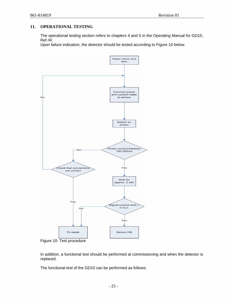
11. OPERATIONAL TESTING
The operational testing section refers to chapters 4 and 5 in the Operating Manual for GD10, Ref /4/. Upon failure indication, the detector should be tested according to Figure 10 below.
Figure 10: Test procedure
In addition, a functional test should be performed at commissioning and when the detector is replaced. The functional test of the GD10 can be performed as follows:
861-814819 Revision 01
- 26 -
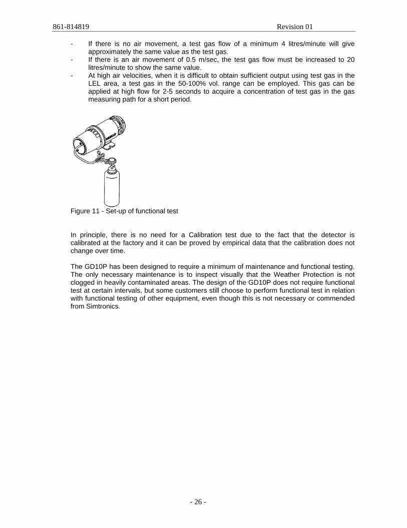
- If there is no air movement, a test gas flow of a minimum 4 litres/minute will give
approximately the same value as the test gas. - If there is an air movement of 0.5 m/sec, the test gas flow must be increased to 20
litres/minute to show the same value. - At high air velocities, when it is difficult to obtain sufficient output using test gas in the
LEL area, a test gas in the 50-100% vol. range can be employed. This gas can be applied at high flow for 2-5 seconds to acquire a concentration of test gas in the gas measuring path for a short period.
Figure 11 - Set-up of functional test In principle, there is no need for a Calibration test due to the fact that the detector is calibrated at the factory and it can be proved by empirical data that the calibration does not change over time. The GD10P has been designed to require a minimum of maintenance and functional testing. The only necessary maintenance is to inspect visually that the Weather Protection is not clogged in heavily contaminated areas. The design of the GD10P does not require functional test at certain intervals, but some customers still choose to perform functional test in relation with functional testing of other equipment, even though this is not necessary or commended from Simtronics.
861-814819 Revision 01
- 27 -
12. ARCHITECTURAL CONSTRAINTS
12.1 General
The Hardware Fault Tolerance (HFT) requirements for an E/E/PE safety-related system con-taining type B sub-systems is given in IEC 61508 -2, sub clause 7.4, Ref. /1/. A type A sub-system is in IEC 61508 terminology a system where all possible failure modes can be determined for all constituent components. For type B sub-systems, the behaviour under fault conditions can not be completely determined for at least one component (e.g. a logic solver). The GD10 Gas Detector is a type B system as it contains software in form of a micro processor.
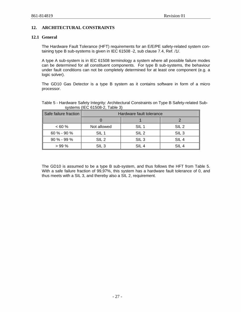
Table 5 - Hardware Safety Integrity: Architectural Constraints on Type B Safety-related Sub-
systems (IEC 61508-2, Table 3) Hardware fault tolerance Safe failure fraction
0 1 2 < 60 % Not allowed SIL 1 SIL 2
60 % - 90 % SIL 1 SIL 2 SIL 3 90 % - 99 % SIL 2 SIL 3 SIL 4
> 99 % SIL 3 SIL 4 SIL 4 The GD10 is assumed to be a type B sub-system, and thus follows the HFT from Table 5. With a safe failure fraction of 99,97%, this system has a hardware fault tolerance of 0, and thus meets with a SIL 3, and thereby also a SIL 2, requirement.
861-814819 Revision 01
- 28 -
13. AVOIDANCE AND CONTROL OF SYSTEMATIC FAILURES
Systematic faults are faults in hardware and software introduced during specification, design, operation or maintenance/testing, which may result in the failure of the safety function under certain conditions, e.g. for particular input signal states. These failures are, unlike random hardware faults, not quantified in IEC 61058/61511 methodology. In order to avoid and control this category of failures it is required in IEC 61508 that certain techniques and measures shall be used to avoid and control this category of failures. The standard has adopted a qualitative approach to address the implementation of the measures. The respective requirements concerning hardware and software are given in IEC 61508-2 and IEC 61508-3. The standard provides tables that specify in which areas/processes systematic failures must be addressed. The tables define the required effectiveness of the techniques applied, and the importance of using the different measures is also specified. A great variety of techniques can be applied and the standard provides examples/recommendations in IEC 61508-7. According to IEC61508-2 clause 7.4.4 and 7.4.5 the requirement related to avoidance and control of systematic failures will not apply to a subsystem considered “proven in use”. The term “proven in use” is defined by clause 7.4.6 to 7.4.12 in IEC 61508-2.
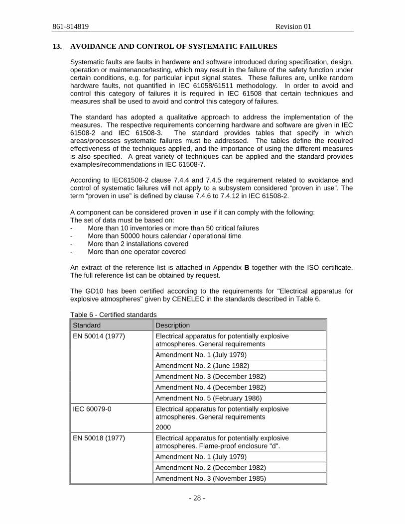
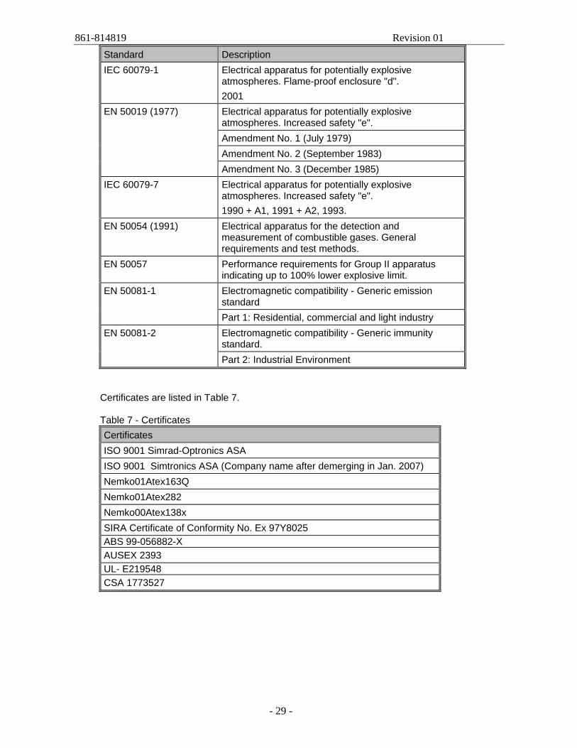
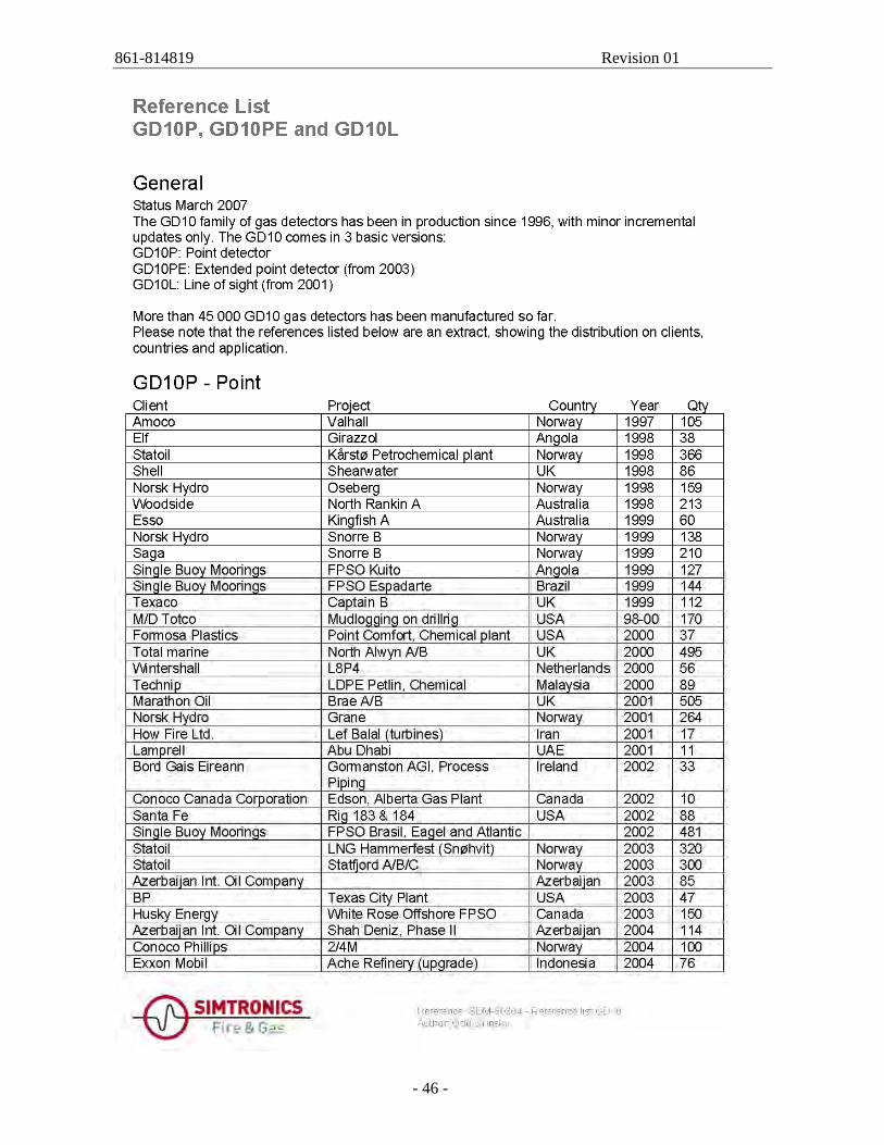
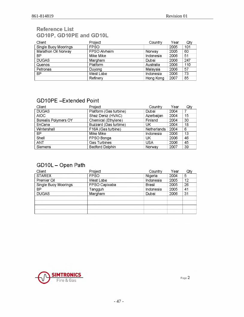
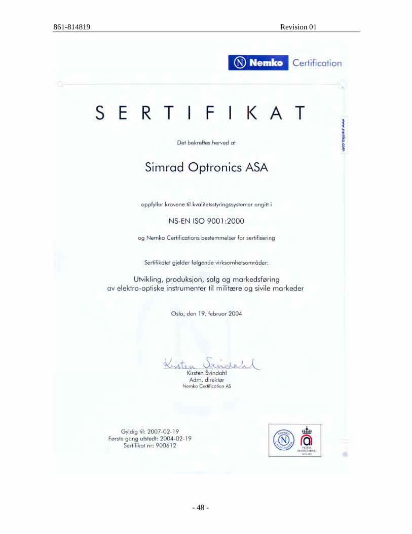
A component can be considered proven in use if it can comply with the following: The set of data must be based on: - More than 10 inventories or more than 50 critical failures - More than 50000 hours calendar / operational time - More than 2 installations covered - More than one operator covered An extract of the reference list is attached in Appendix B together with the ISO certificate. The full reference list can be obtained by request. The GD10 has been certified according to the requirements for "Electrical apparatus for explosive atmospheres" given by CENELEC in the standards described in Table 6. Table 6 - Certified standards Standard Description
Electrical apparatus for potentially explosive atmospheres. General requirements Amendment No. 1 (July 1979) Amendment No. 2 (June 1982) Amendment No. 3 (December 1982) Amendment No. 4 (December 1982)
EN 50014 (1977)
Amendment No. 5 (February 1986) IEC 60079-0 Electrical apparatus for potentially explosive
atmospheres. General requirements 2000 Electrical apparatus for potentially explosive atmospheres. Flame-proof enclosure "d". Amendment No. 1 (July 1979) Amendment No. 2 (December 1982)
EN 50018 (1977)
Amendment No. 3 (November 1985)
861-814819 Revision 01
- 29 -
Standard Description IEC 60079-1 Electrical apparatus for potentially explosive
atmospheres. Flame-proof enclosure "d". 2001 Electrical apparatus for potentially explosive atmospheres. Increased safety "e". Amendment No. 1 (July 1979) Amendment No. 2 (September 1983)
EN 50019 (1977)
Amendment No. 3 (December 1985) IEC 60079-7 Electrical apparatus for potentially explosive
atmospheres. Increased safety "e". 1990 + A1, 1991 + A2, 1993.
EN 50054 (1991) Electrical apparatus for the detection and measurement of combustible gases. General requirements and test methods.
EN 50057 Performance requirements for Group II apparatus indicating up to 100% lower explosive limit. Electromagnetic compatibility - Generic emission standard
EN 50081-1
Part 1: Residential, commercial and light industry Electromagnetic compatibility - Generic immunity standard.
EN 50081-2
Part 2: Industrial Environment
Certificates are listed in Table 7.
Table 7 - Certificates Certificates ISO 9001 Simrad-Optronics ASA ISO 9001 Simtronics ASA (Company name after demerging in Jan. 2007) Nemko01Atex163Q Nemko01Atex282 Nemko00Atex138x SIRA Certificate of Conformity No. Ex 97Y8025 ABS 99-056882-X AUSEX 2393 UL- E219548 CSA 1773527
861-814819 Revision 01
- 30 -
14. SOFTWARE DOCUMENTATION
Documentation for the micro processor can be found in the Program Specification, document no 803-810784.9 version 6, and the Software Safety Requirements, document no 803-810663.5. Please contact Simtronics to view these documents.
861-814819 Revision 01
- 31 -
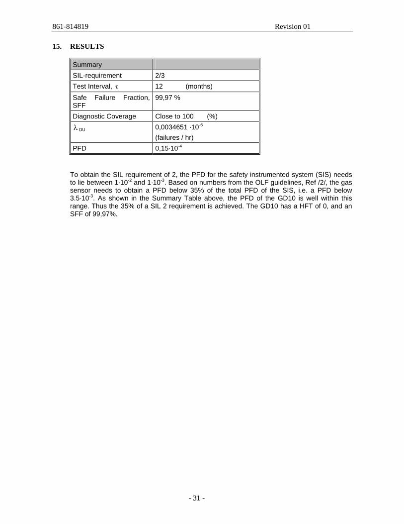
15. RESULTS
Summary SIL-requirement 2/3 Test Interval, τ 12 (months) Safe Failure Fraction, SFF
99,97 %
Diagnostic Coverage Close to 100 (%) λ DU 0,0034651 ·10-6
(failures / hr) PFD 0,15·10-4
To obtain the SIL requirement of 2, the PFD for the safety instrumented system (SIS) needs to lie between 1·10-2 and 1·10-3. Based on numbers from the OLF guidelines, Ref /2/, the gas sensor needs to obtain a PFD below 35% of the total PFD of the SIS, i.e. a PFD below 3.5·10-3. As shown in the Summary Table above, the PFD of the GD10 is well within this range. Thus the 35% of a SIL 2 requirement is achieved. The GD10 has a HFT of 0, and an SFF of 99,97%.
861-814819 Revision 01
- 32 -
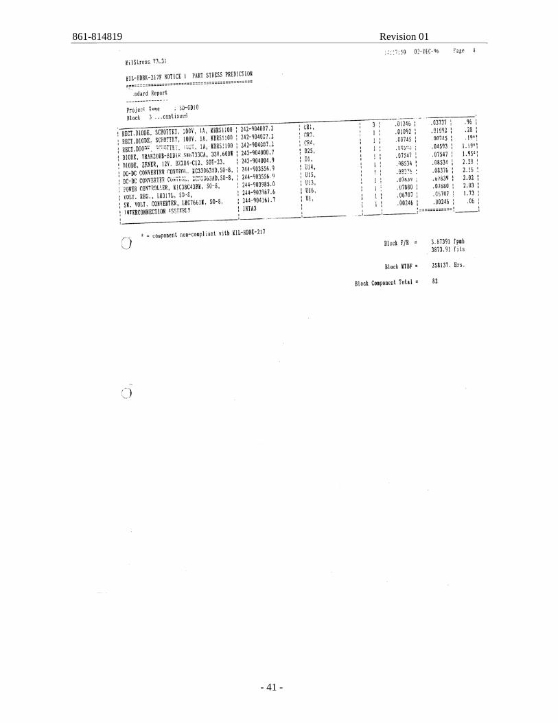
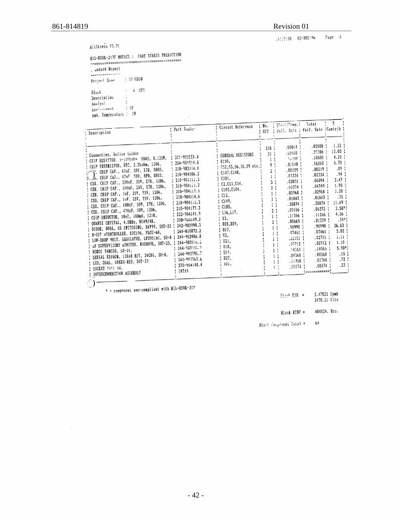
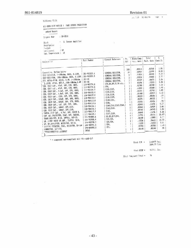
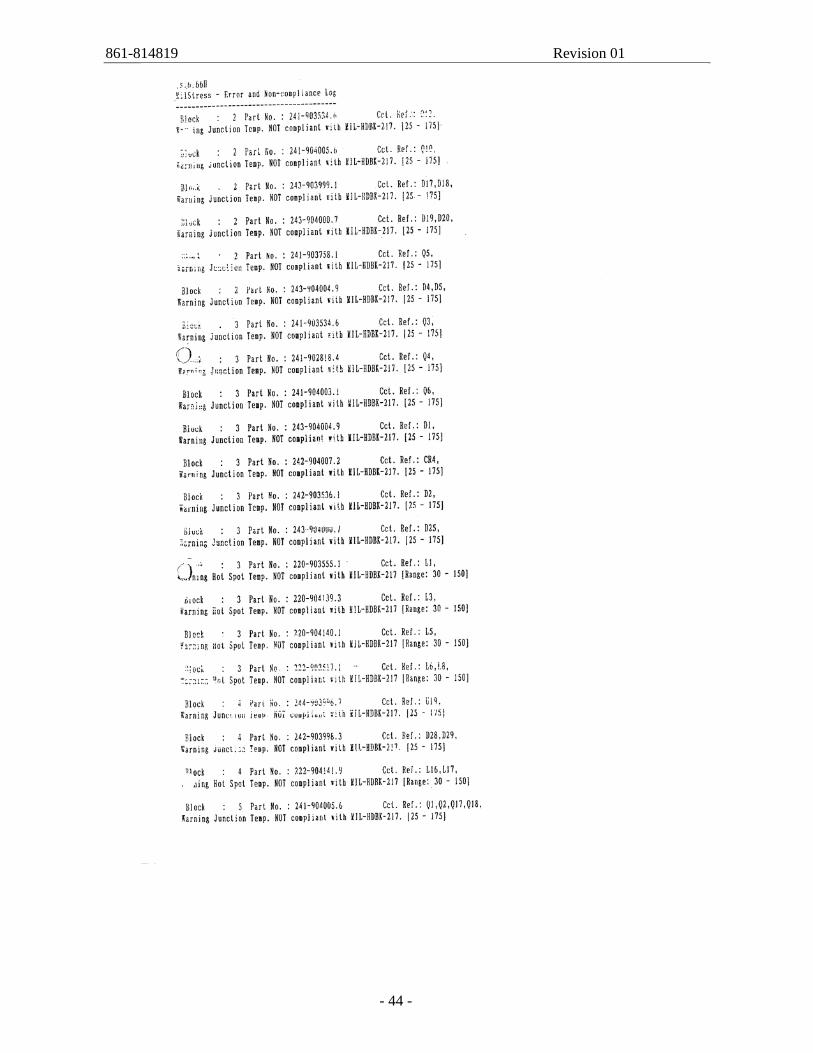
Appendix A: Failure Rate Data
861-814819 Revision 01
- 33 -
861-814819 Revision 01
- 34 -
861-814819 Revision 01
- 35 -
861-814819 Revision 01
- 36 -
861-814819 Revision 01
- 37 -
861-814819 Revision 01
- 38 -
861-814819 Revision 01
- 39 -
861-814819 Revision 01
- 40 -
861-814819 Revision 01
- 41 -
861-814819 Revision 01
- 42 -
861-814819 Revision 01
- 43 -
861-814819 Revision 01
- 44 -
861-814819 Revision 01
- 45 -
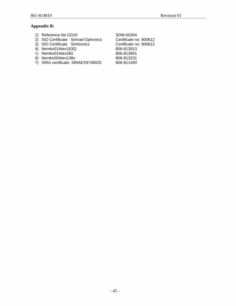
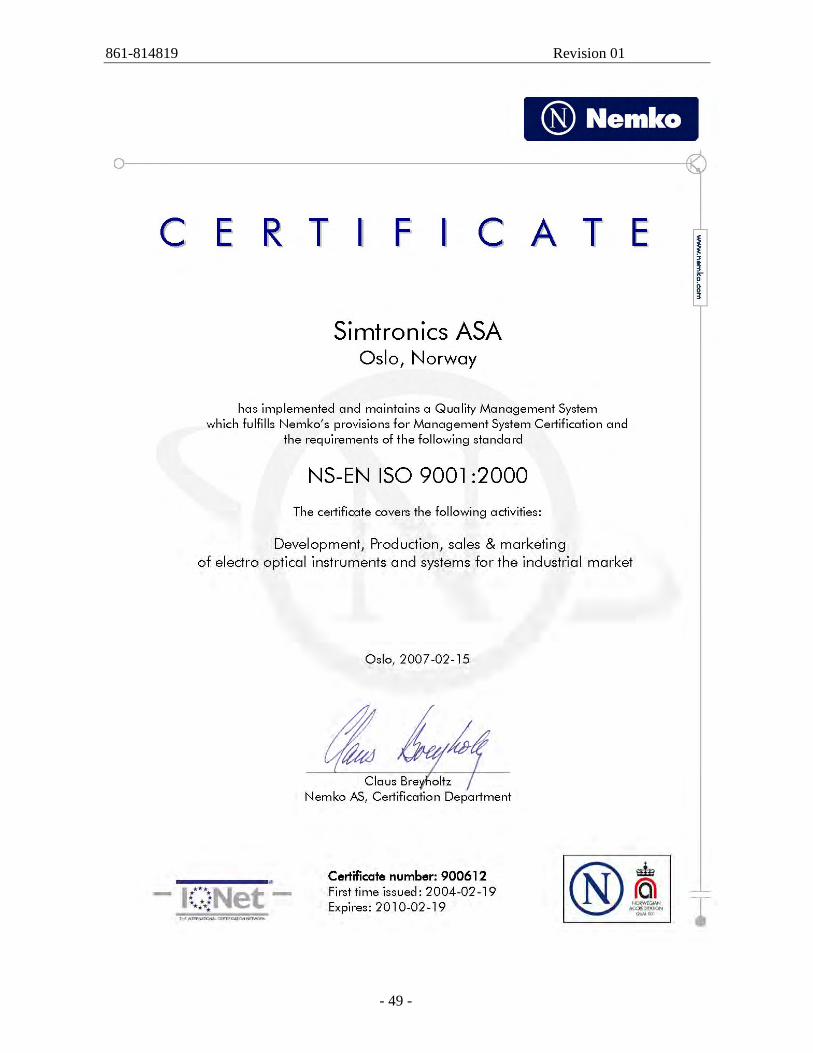
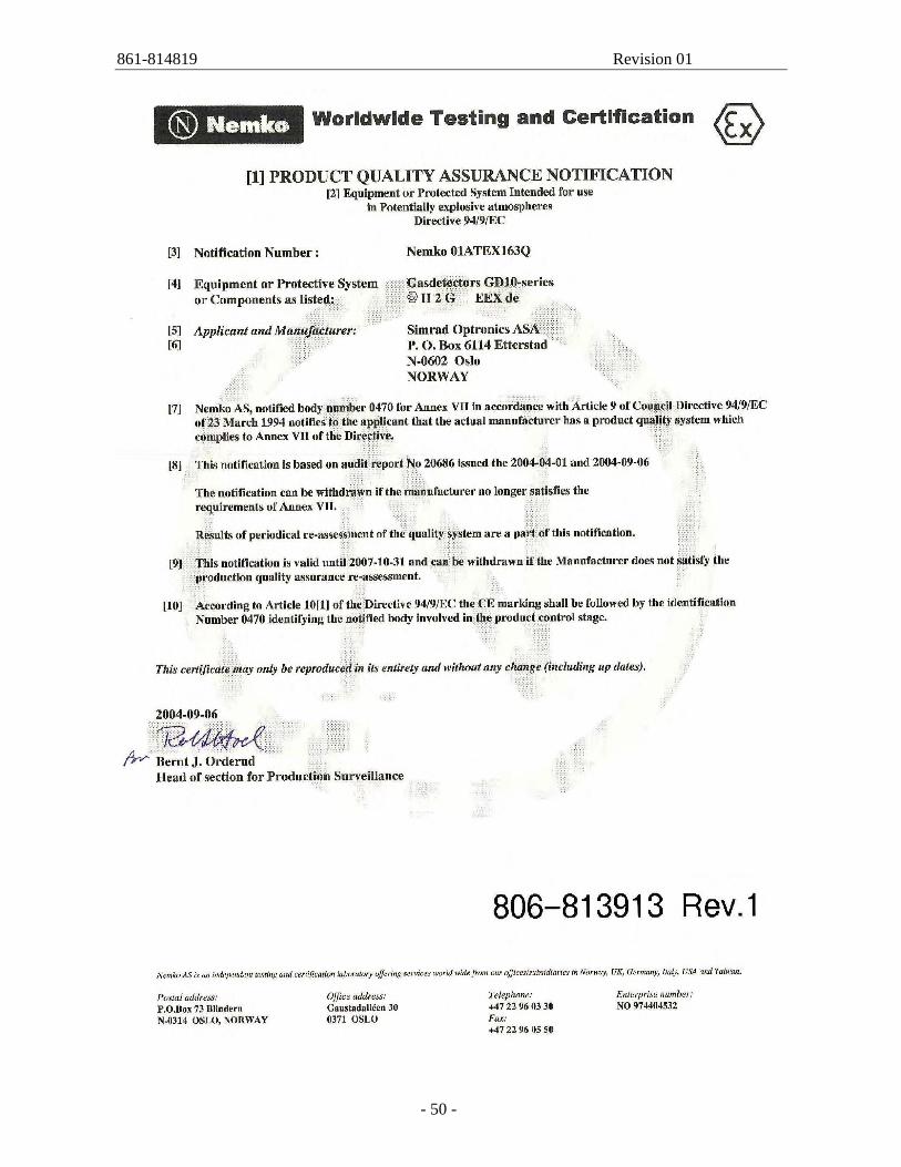
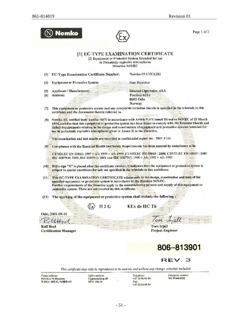
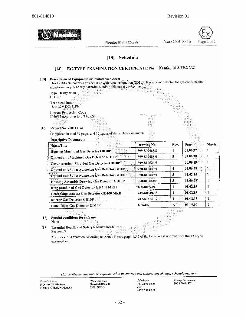
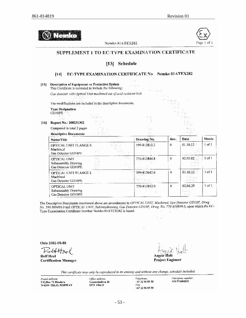
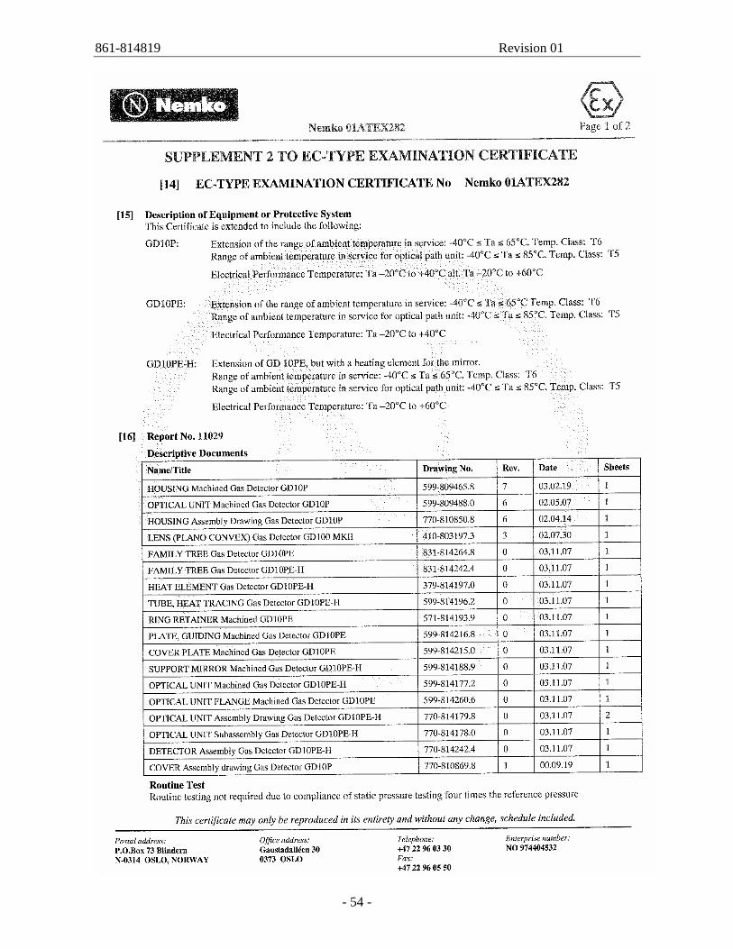
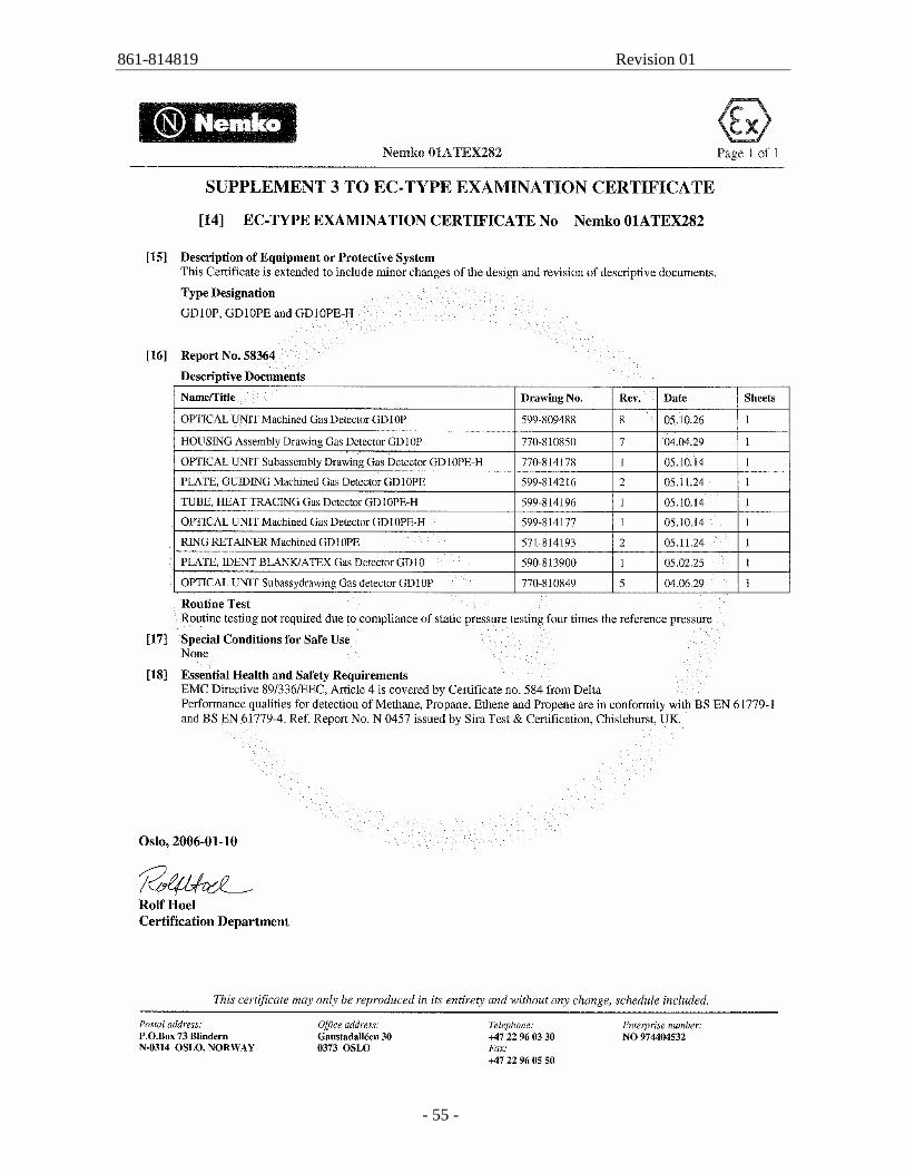
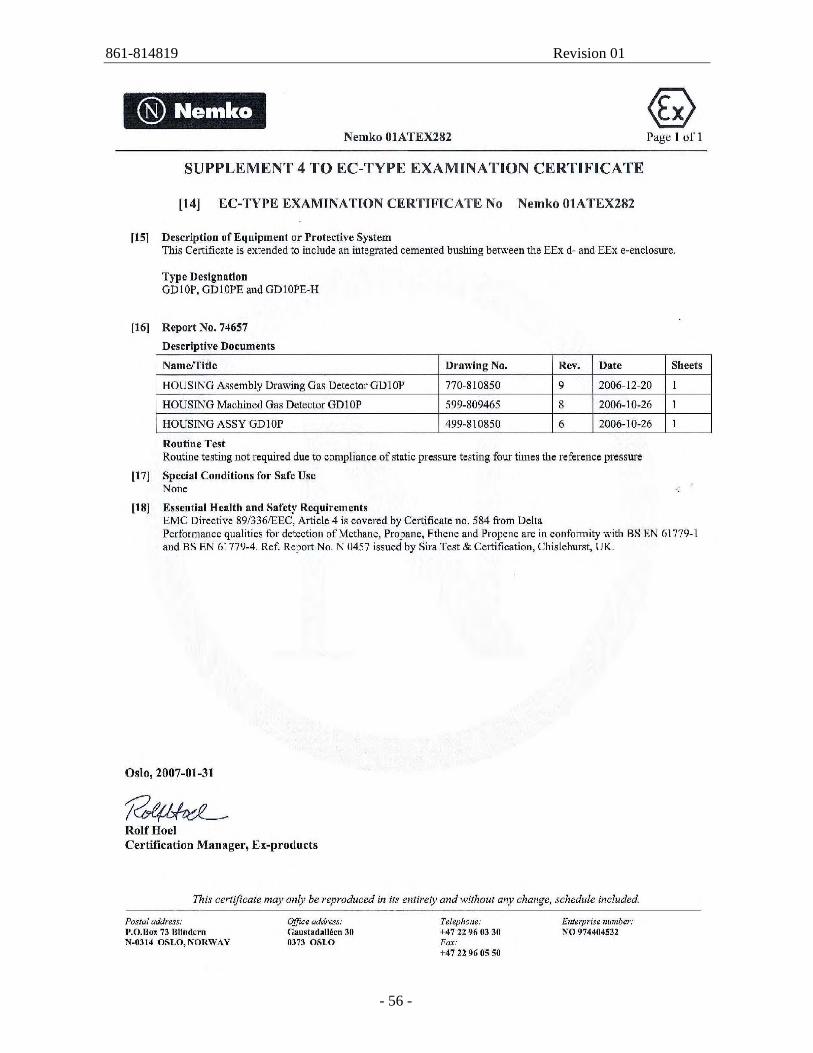
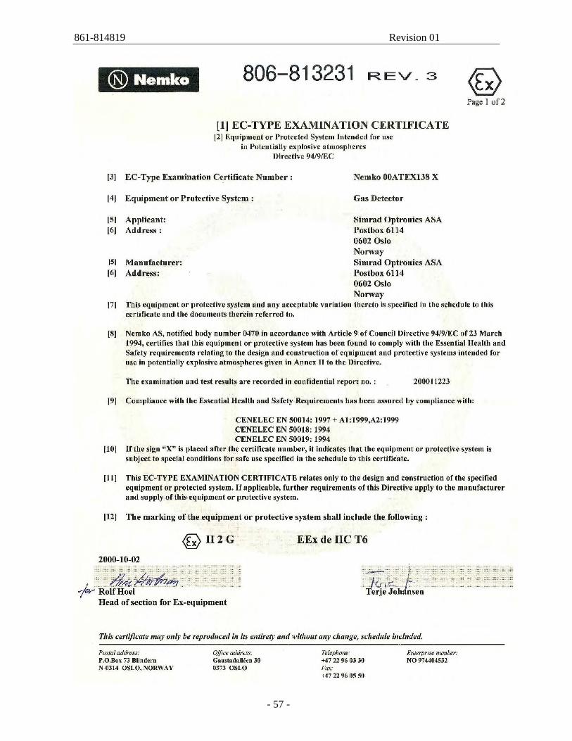
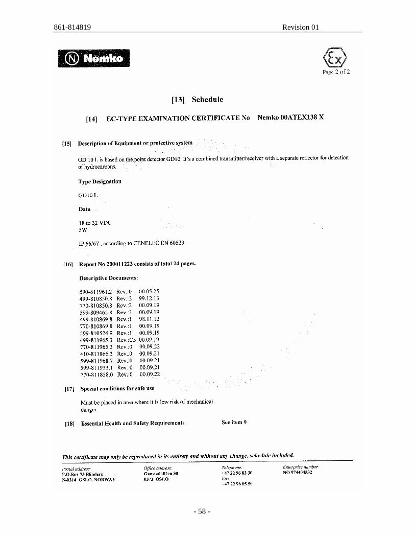
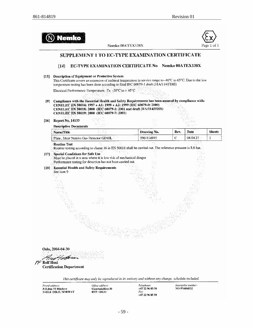
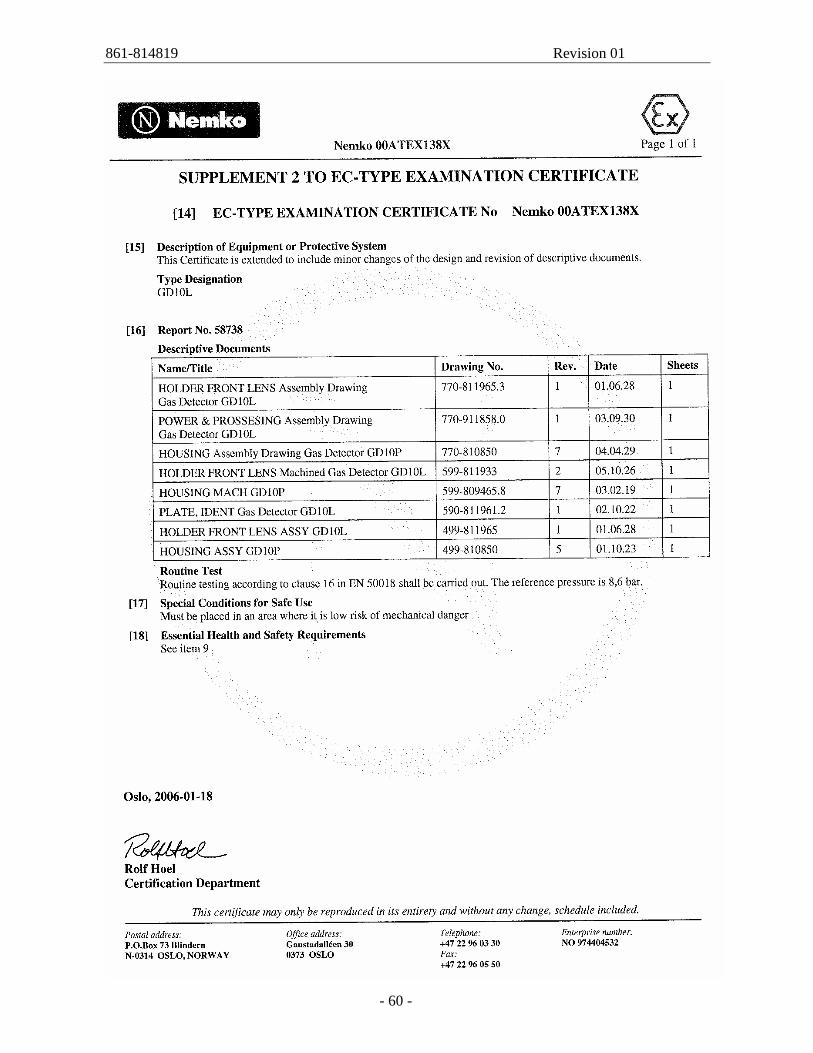
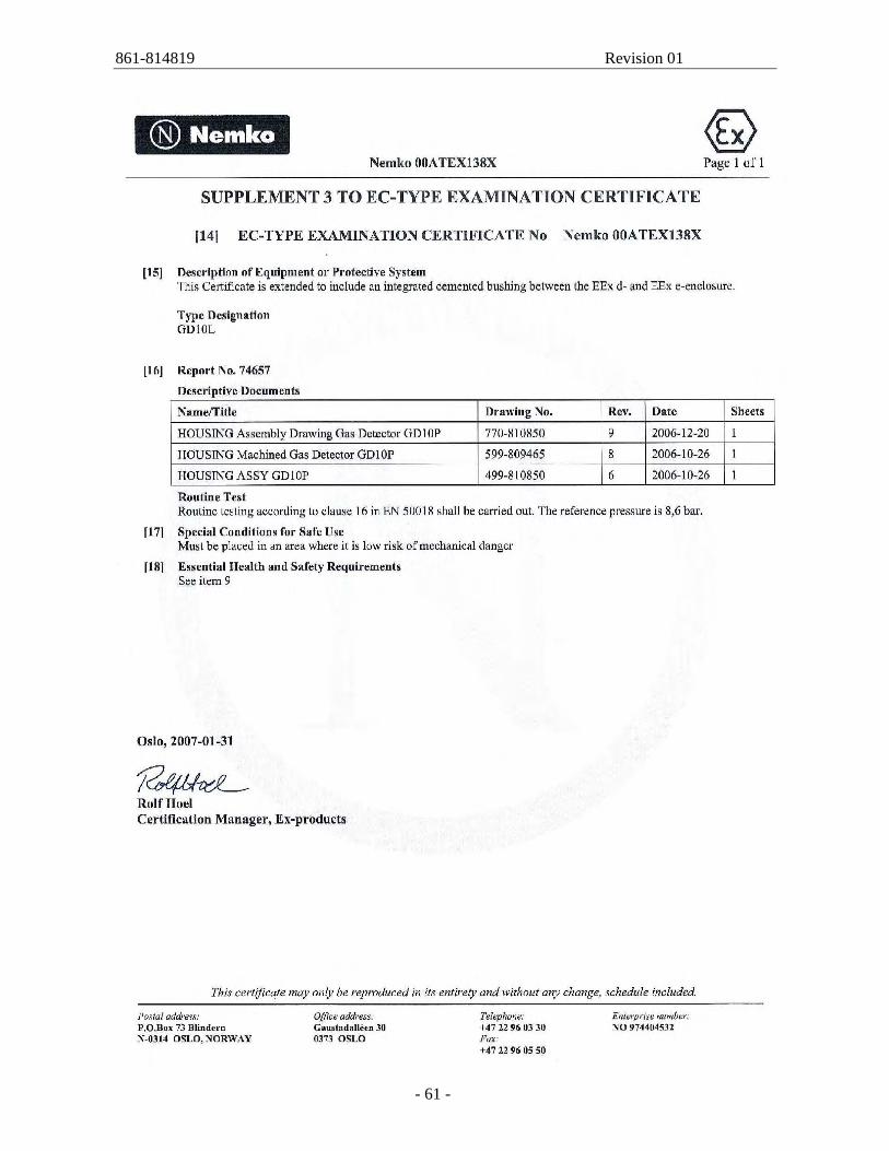
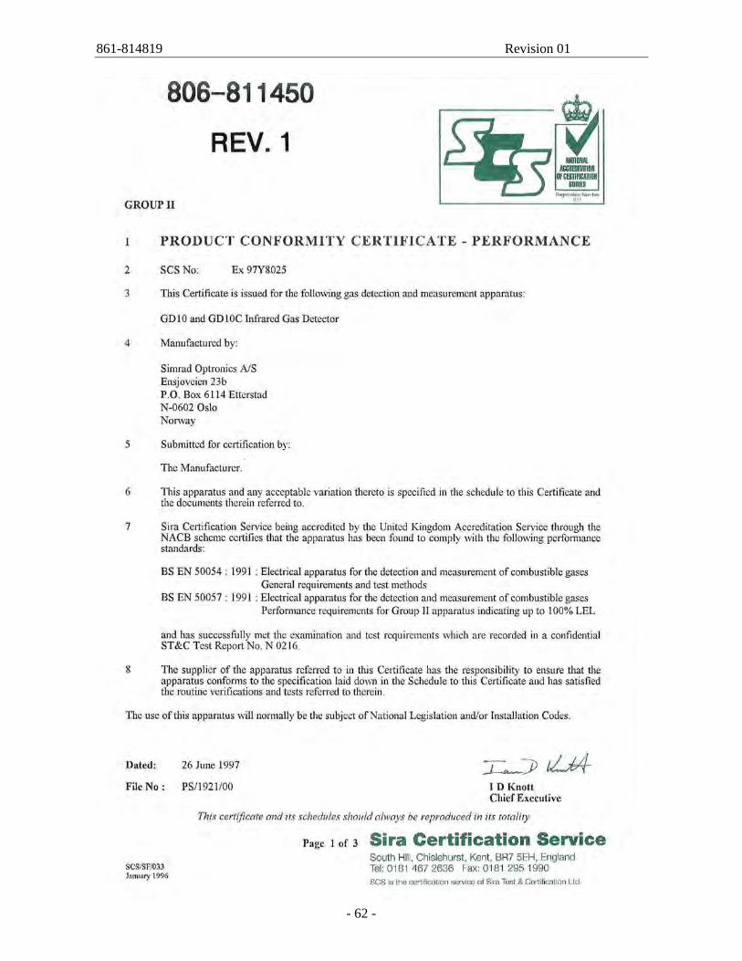
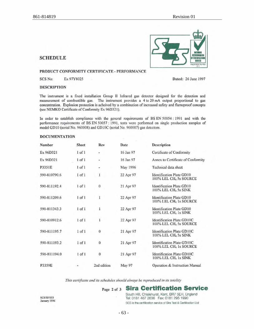
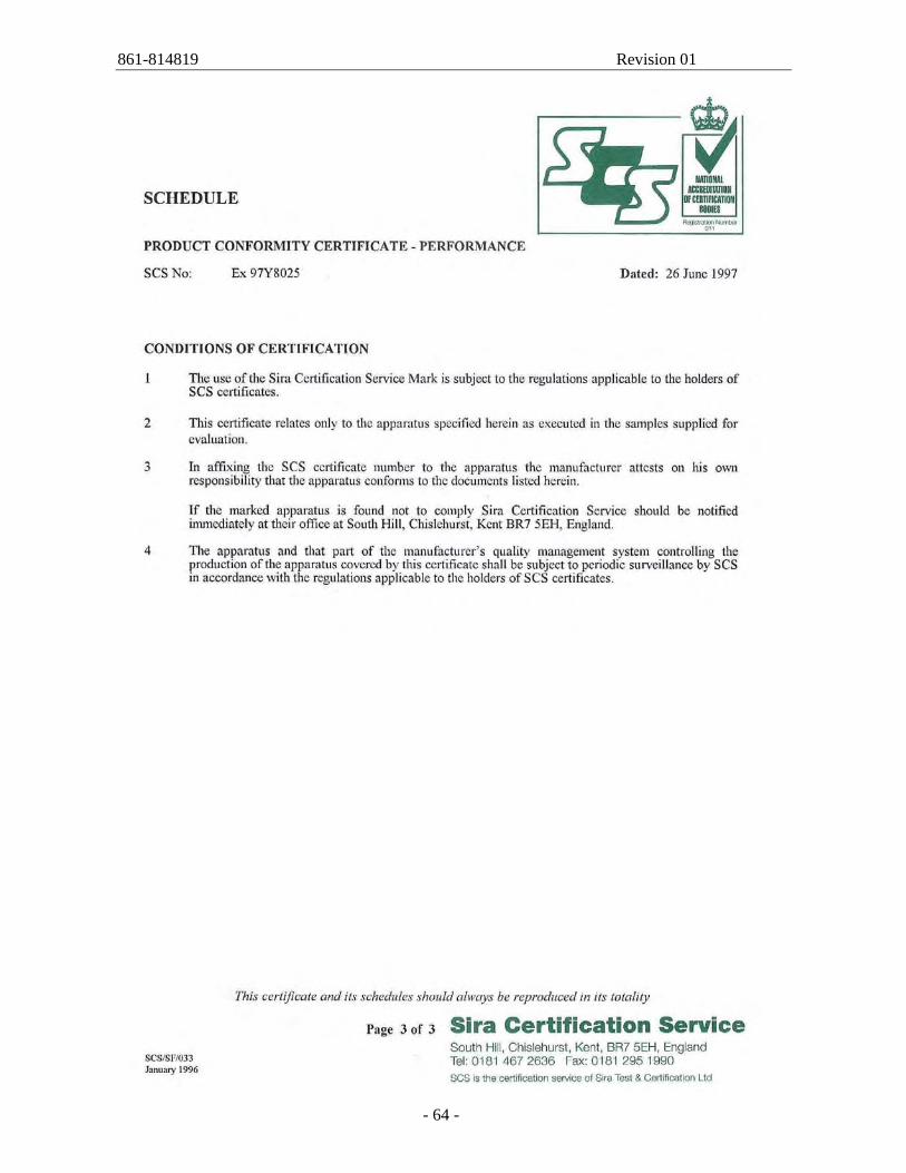
Appendix B: 1) Reference list GD10 SDM-60304 2) ISO Certificate Simrad-Optronics Certificate no: 900612 3) ISO Certificate Simtronics Certificate no: 900612 4) Nemko01Atex163Q 806-813913 5) Nemko01Atex282 806-813901 6) Nemko00Atex138x 806-813231 7) SIRA certificate: SIRAEX9748025 806-811450
861-814819 Revision 01
- 46 -
861-814819 Revision 01
- 47 -
861-814819 Revision 01
- 48 -
861-814819 Revision 01
- 49 -
861-814819 Revision 01
- 50 -
861-814819 Revision 01
- 51 -
861-814819 Revision 01
- 52 -
861-814819 Revision 01
- 53 -
861-814819 Revision 01
- 54 -
861-814819 Revision 01
- 55 -
861-814819 Revision 01
- 56 -
861-814819 Revision 01
- 57 -
861-814819 Revision 01
- 58 -
861-814819 Revision 01
- 59 -
861-814819 Revision 01
- 60 -
861-814819 Revision 01
- 61 -
861-814819 Revision 01
- 62 -
861-814819 Revision 01
- 63 -
861-814819 Revision 01
- 64 -
861-814819 Revision 01
- 65 -
861-814819 Revision 01
- 66 -
861-814819 Revision 01
- 67 -