residual stress review - University of Cincinnati
20
Case Study: Residual Stress Measurement
Transcript of residual stress review - University of Cincinnati
Case Study:
Residual Stress Measurement
Life Prediction/Prognostics
106102
intact (no residual stress)
with opposite residual stress
Fatigue Life [cycles]104 108
0
500
1000
1500
endurancelimit
service load
life timenatural
life timeincreasedA
ltern
atin
g St
ress
[MPa
]
Residual stresses have numerous origins that are highly variable.Residual stresses relax at service temperatures.
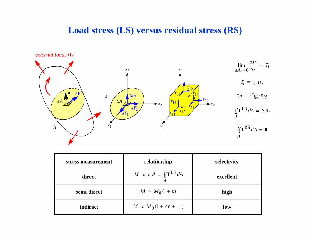
lowindirect
highsemi-direct
excellentdirect
selectivityrelationshipstress measurement
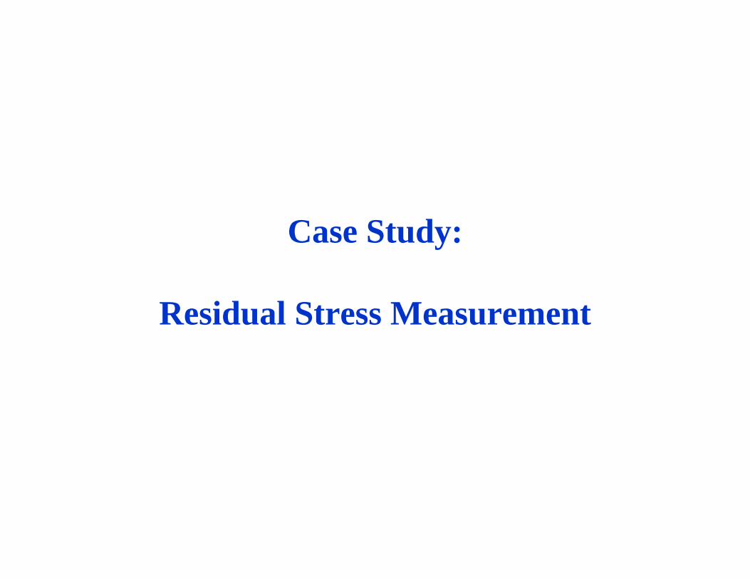
Load stress (LS) versus residual stress (RS)
0 (1 )M M≈ + ε
τ23F3Δ
AΔ
A
AΔA
FΔn
external loads L( )
x1
x2
x3
x1
x2
x3
F2ΔF1Δ
τ33
τ32
τ13
τ31
τ12τ11
τ22τ21
0 (1 ... )M M≈ + ηε +
LS
AdA = ∑∫∫T L
RS
AdA =∫∫T 0
0lim i
iA
F TAΔ →
Δ=
Δ
i ij jT n= τ
ij ijkl klCτ = ε
LS
AM A dA≈ τ = ∫∫ T
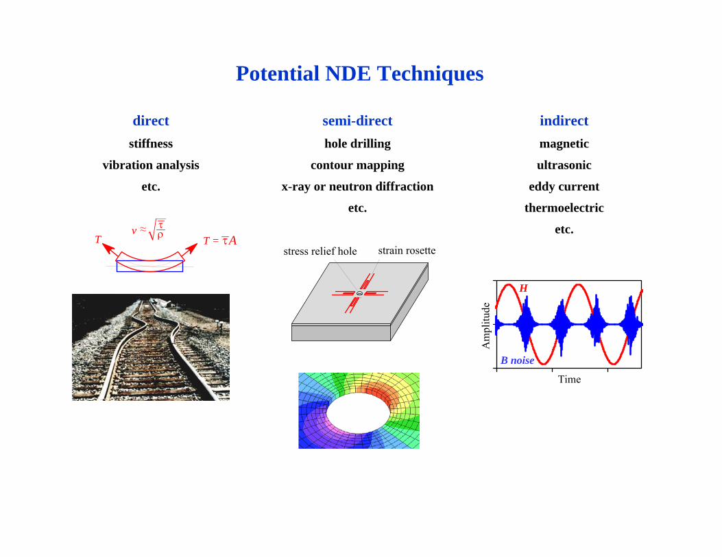
Potential NDE Techniques
directstiffness
vibration analysis
etc.
semi-directhole drilling
contour mapping
x-ray or neutron diffraction
etc.
indirectmagnetic
ultrasonic
eddy current
thermoelectric
etc.strain rosettestress relief hole
Time
Am
plitu
de
H
B noise
T T = Aτ τρv ≈
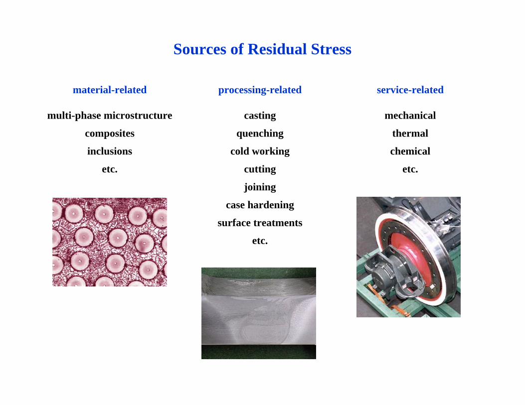
Sources of Residual Stress
material-related
multi-phase microstructure
composites
inclusions
etc.
processing-related
casting
quenching
cold working
cutting
joining
case hardening
surface treatments
etc.
service-related
mechanical
thermal
chemical
etc.
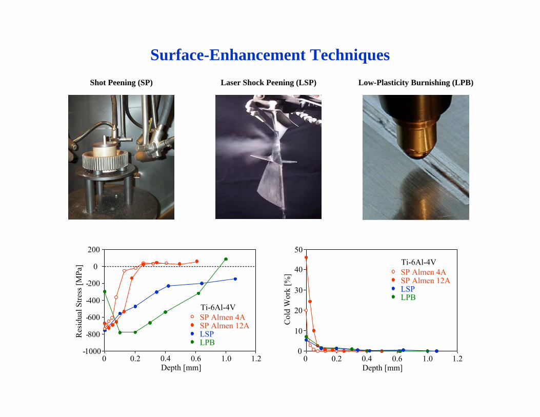
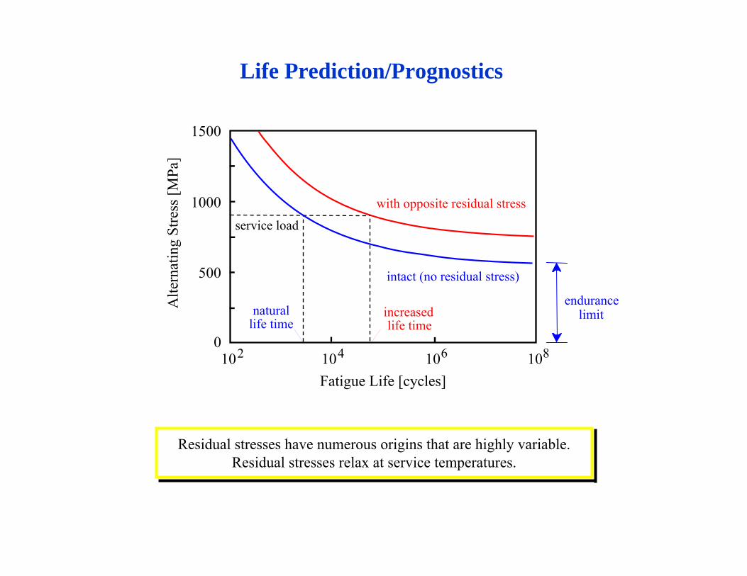
Surface-Enhancement TechniquesLow-Plasticity Burnishing (LPB)Shot Peening (SP) Laser Shock Peening (LSP)
Depth [mm]0 0.2 0.4 0.6 1.0 1.2
200
0
-200
-400
-600
-800
-1000
Res
idua
l Stre
ss [M
Pa]
SP Almen 12ASP Almen 4A
LSPLPB
Ti-6Al-4V
0 0.2 0.4 0.6 1.0 1.2Depth [mm]
Col
d W
ork
[%] 40
30
20
10
0
50
SP Almen 12ASP Almen 4A
LSPLPB
Ti-6Al-4V
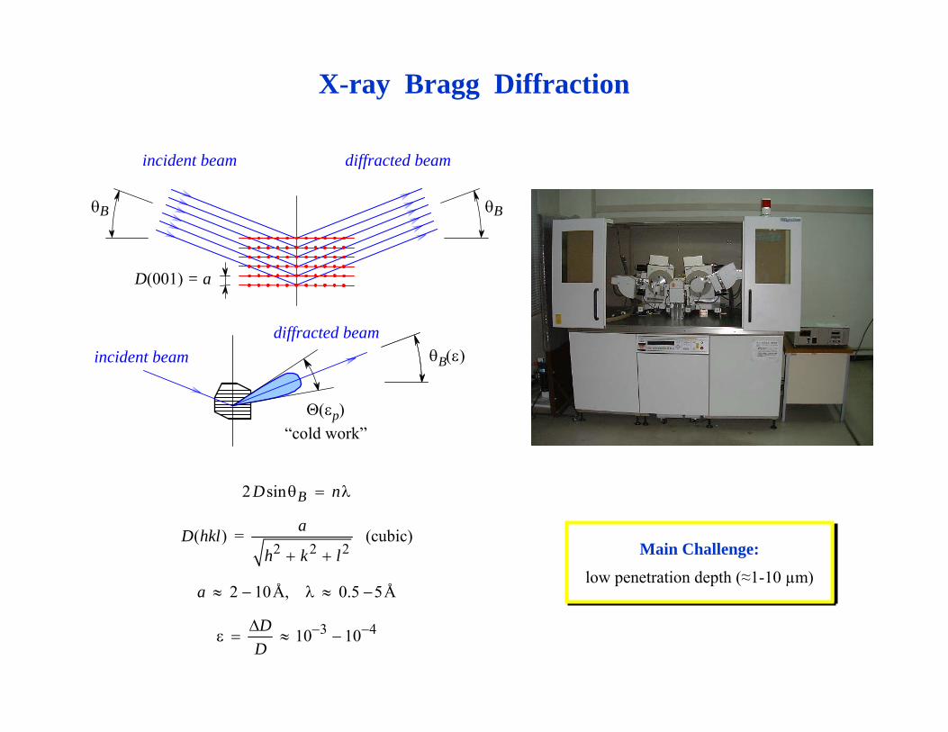
X-ray Bragg Diffraction
2 2 2
3 4
2 sin
( ) = (cubic)
2 10Å, 0.5 5Å
10 10
BD n
aD hklh k l
a
DD
− −
θ = λ
+ +
≈ − λ ≈ −
Δε = ≈ −
incident beam diffracted beam
D(001) = a
θB θB
incident beamdiffracted beam
Θ(εp)“cold work”
θB(ε)
Main Challenge:
low penetration depth (≈1-10 µm)
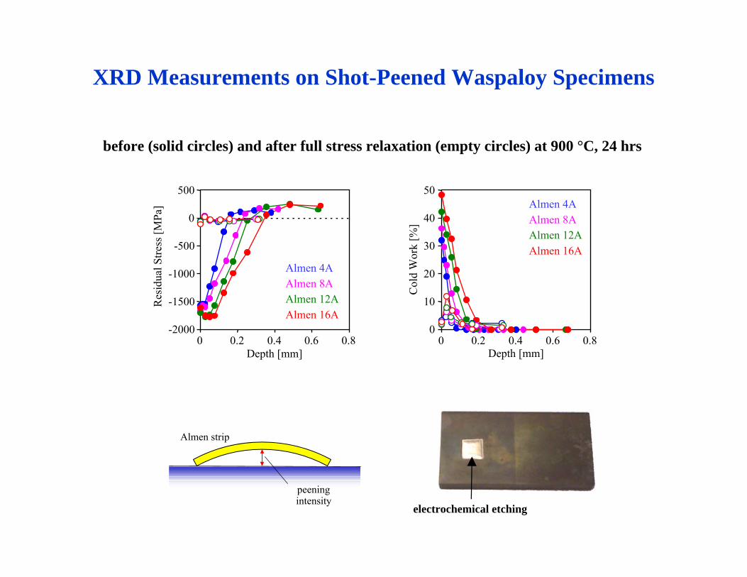
before (solid circles) and after full stress relaxation (empty circles) at 900 °C, 24 hrs
XRD Measurements on Shot-Peened Waspaloy Specimens
electrochemical etching
-2000
-1500
-1000
-500
0
500
0 0.2 0.4 0.6 0.8Depth [mm]
Res
idua
l Stre
ss [M
Pa]
Almen 4AAlmen 8AAlmen 12AAlmen 16A
0
10
20
30
40
50
0 0.2 0.4 0.6 0.8
Col
d W
ork
[%]
Almen 4AAlmen 8AAlmen 12AAlmen 16A
Depth [mm]
peeningintensity
Almen strip
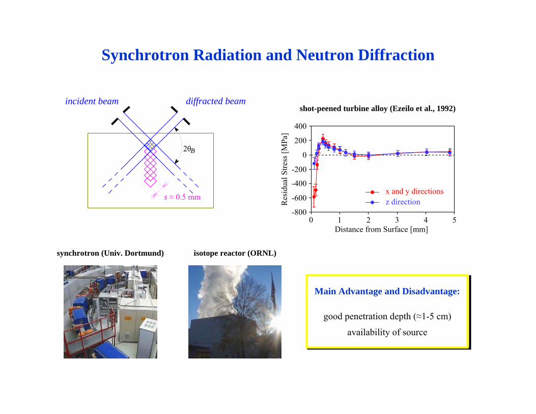
Synchrotron Radiation and Neutron Diffraction
Main Advantage and Disadvantage:
good penetration depth (≈1-5 cm)
availability of source
2θB
incident beam diffracted beam
s ≈ 0.5 mm
isotope reactor (ORNL) synchrotron (Univ. Dortmund)
shot-peened turbine alloy (Ezeilo et al., 1992)
x and y directionsz direction
Distance from Surface [mm]20 1 3 4 5
400
200
-400
-200
-800
-600
0
Res
idua
l Stre
ss [M
Pa]
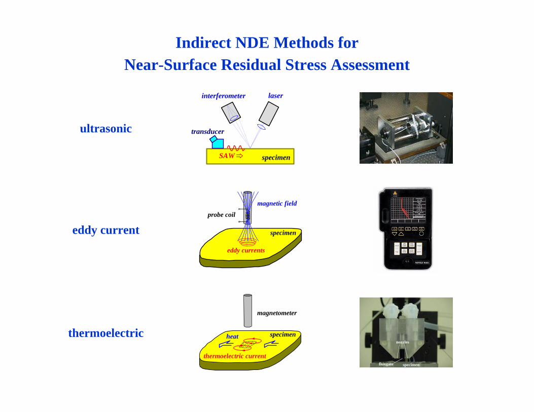
Indirect NDE Methods for Near-Surface Residual Stress Assessment
thermoelectric
fluxgate
nozzles
specimen
specimenheat
thermoelectric current
magnetometer
ultrasonic
SAW
laser
specimen
interferometer
transducer
eddy current specimen
eddy currents
probe coil
magnetic field
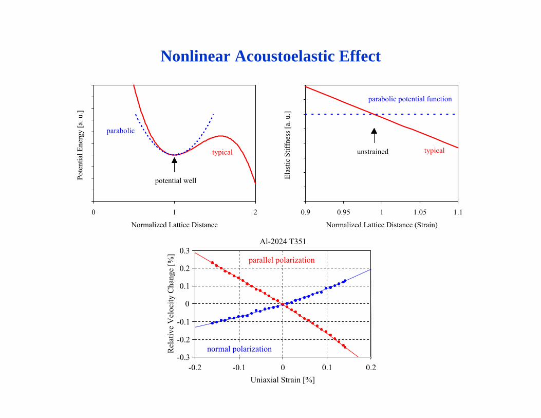
Nonlinear Acoustoelastic Effect
Normalized Lattice Distance
Pote
ntia
l Ene
rgy
[a. u
.]
0 1 2
typical
parabolic
potential well
Al-2024 T351
-0.3
-0.2
-0.1
0
0.1
0.2
0.3
-0.2 -0.1 0 0.1 0.2Uniaxial Strain [%]
Rel
ativ
e V
eloc
ity C
hang
e [%
]
parallel polarization
normal polarization
Normalized Lattice Distance (Strain)
Elas
tic S
tiffn
ess [
a. u
.]
0.9 0.95 1 1.05 1.1
typical
parabolic potential function
unstrained
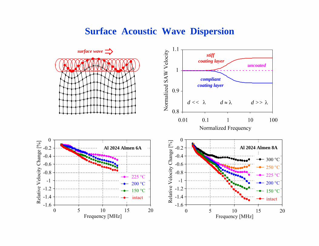
Surface Acoustic Wave Dispersion
0.8
0.9
1
1.1
0.01 0.1 1 10 100Normalized Frequency
Nor
mal
ized
SA
W V
eloc
ity
stiff coating layer
compliantcoating layer
uncoated
λd << d >> λd ≈ λ
surface wave
-1.6-1.4-1.2
-1-0.8-0.6-0.4-0.2
0
0 5 10 15 20Frequency [MHz]
Rel
ativ
e V
eloc
ity C
hang
e [%
] a
300 °C250 °C225 °C200 °C
150 °Cintact
Al 2024 Almen 8A
Rel
ativ
e V
eloc
ity C
hang
e [%
]
-1.6-1.4-1.2
-1-0.8-0.6-0.4-0.2
0
0 5 10 15 20Frequency [MHz]
225 °C200 °C150 °Cintact
Al 2024 Almen 6A

Indirect NDE Methods for Near-Surface Residual Stress Assessment
thermoelectric
fluxgate
nozzles
specimen
specimenheat
thermoelectric current
magnetometer
ultrasonic
SAW
laser
specimen
interferometer
transducer
eddy current specimen
eddy currents
probe coil
magnetic field
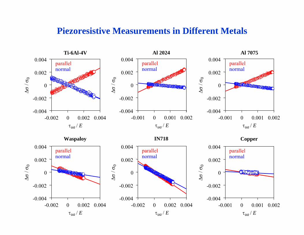
parallel
-0.004
-0.002
0
0.002
0.004
-0.001 0 0.001 0.002τua / E
Δσ /
σ 0
normal
Copper
Ti-6Al-4V
parallel
-0.004
-0.002
0
0.002
0.004
-0.002 0 0.002 0.004τua / E
Δσ /
σ 0
normalparallel
-0.004
-0.002
0
0.002
0.004
-0.001 0 0.001 0.002τua / E
Δσ /
σ 0
normal
Al 2024
parallel
-0.004
-0.002
0
0.002
0.004
-0.001 0 0.001 0.002τua / E
Δσ /
σ 0
normal
Al 7075
Piezoresistive Measurements in Different Metals
Waspaloy
parallel
-0.004
-0.002
0
0.002
0.004
-0.002 0 0.002 0.004τua / E
Δσ /
σ 0
normal
IN718
parallel
-0.004
-0.002
0
0.002
0.004
-0.002 0 0.002 0.004τua / E
Δσ /
σ 0
normal
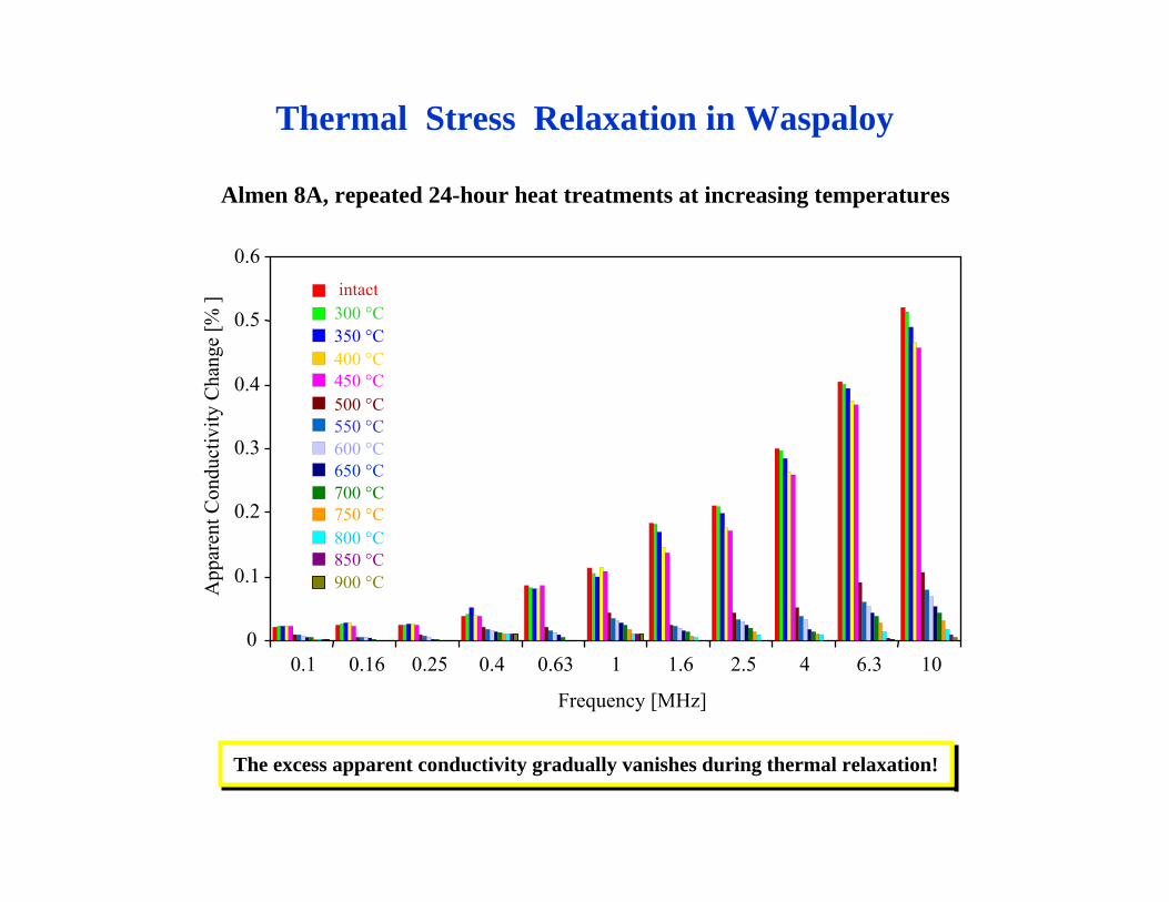
Almen 8A, repeated 24-hour heat treatments at increasing temperatures
0.1 0.16 0.25 0.4 0.63 1 1.6 2.5 4 6.3 10
Frequency [MHz]
0
0.1
0.2
0.3
0.4
0.5
0.6
App
aren
t Con
duct
ivity
Cha
nge
[% ] intact
300 °C350 °C400 °C450 °C500 °C550 °C600 °C650 °C700 °C750 °C800 °C850 °C900 °C
The excess apparent conductivity gradually vanishes during thermal relaxation!
Thermal Stress Relaxation in Waspaloy
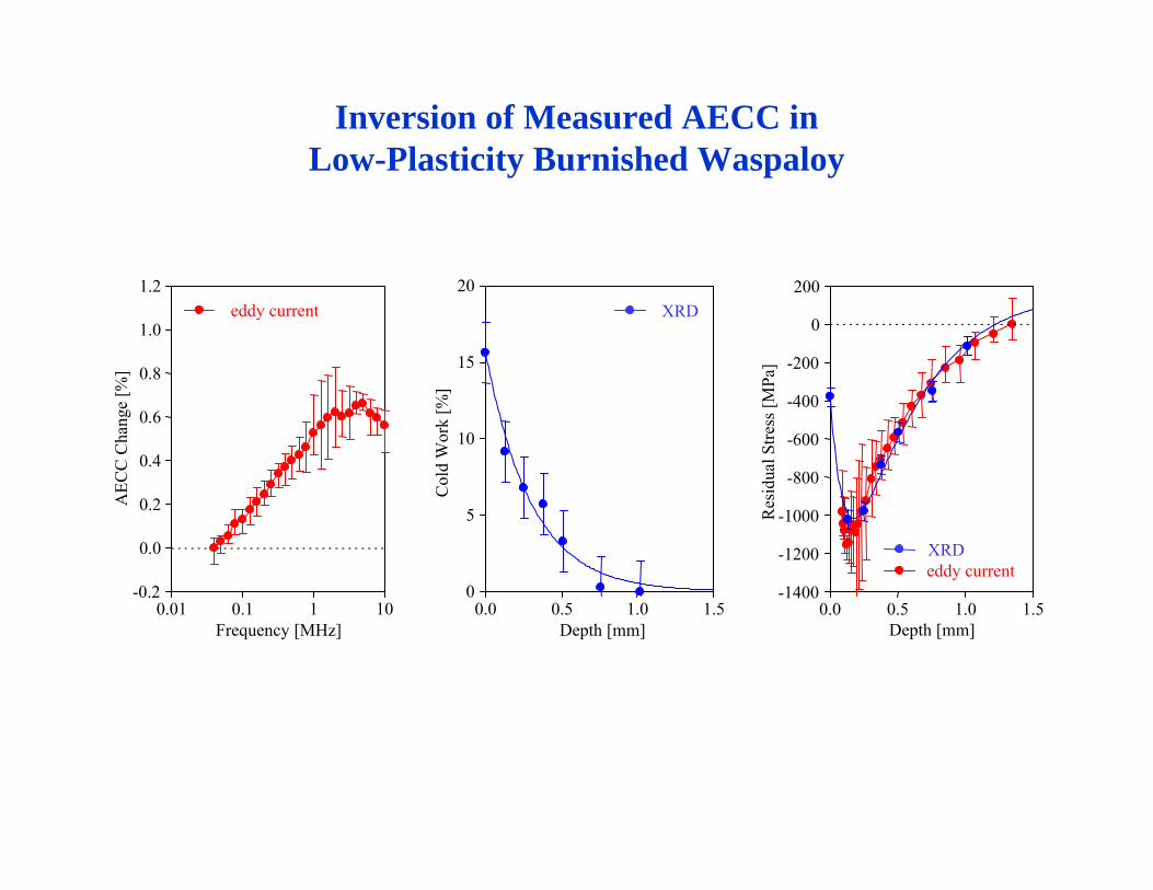
Inversion of Measured AECC in Low-Plasticity Burnished Waspaloy
-0.2
0.0
0.2
0.4
0.6
0.8
1.0
1.2
0.01 0.1 1 10Frequency [MHz]
AEC
C C
hang
e [%
]
eddy current
0.0 0.5 1.0 1.5Depth [mm]
Col
d W
ork
[%]
.
0
5
10
15
20XRD
.
-1400
-1200
-1000
-800
-600
-400
-200
0
200
0.0 0.5 1.0 1.5Depth [mm]
Res
idua
l Stre
ss [M
Pa]
eddy currentXRD

Indirect NDE Methods for Near-Surface Residual Stress Assessment
thermoelectric
fluxgate
nozzles
specimen
specimenheat
thermoelectric current
magnetometer
ultrasonic
SAW
laser
specimen
interferometer
transducer
eddy current specimen
eddy currents
probe coil
magnetic field
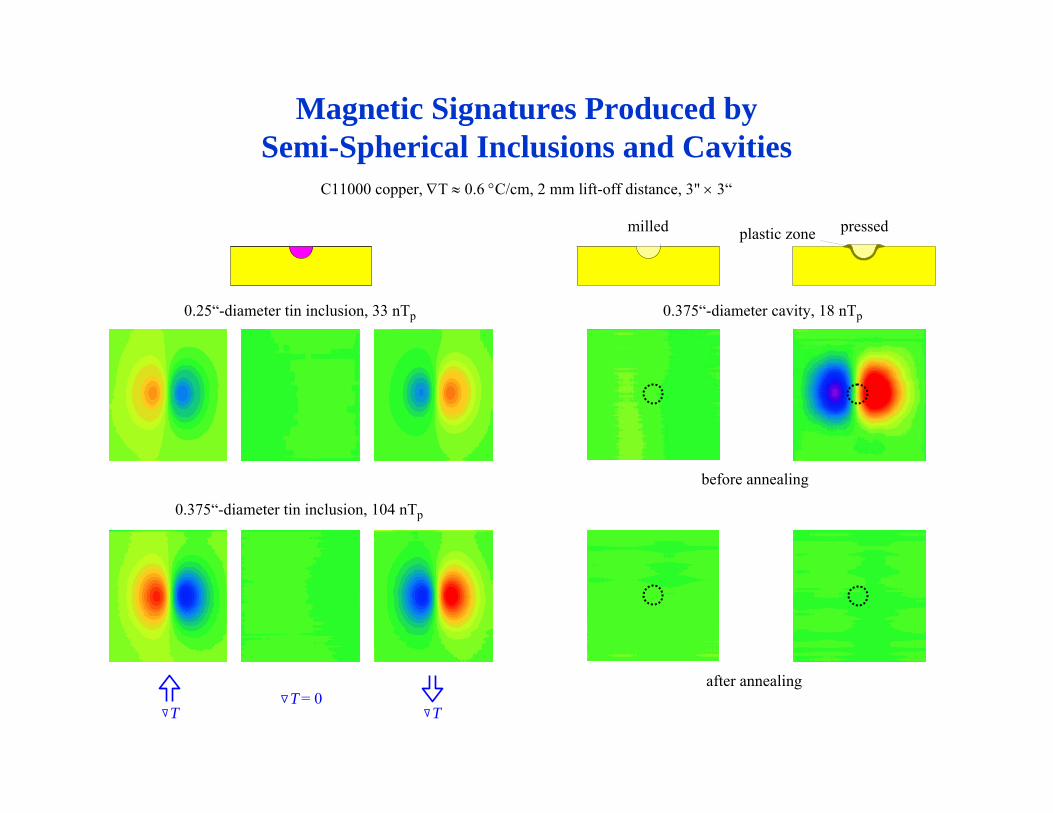
Magnetic Signatures Produced bySemi-Spherical Inclusions and Cavities
milled pressed
before annealing
after annealing
plastic zone
C11000 copper, ∇T ≈ 0.6 °C/cm, 2 mm lift-off distance, 3" × 3“
0.25“-diameter tin inclusion, 33 nTp 0.375“-diameter cavity, 18 nTp
T TT = 0
0.375“-diameter tin inclusion, 104 nTp
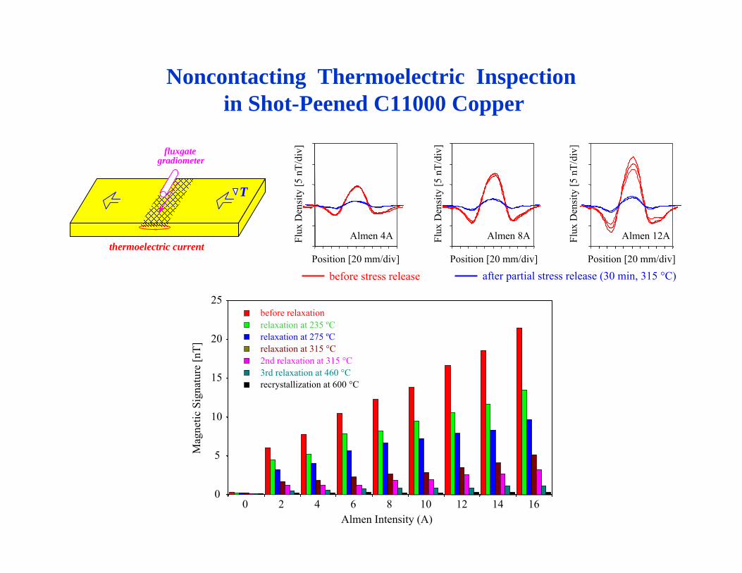
Noncontacting Thermoelectric Inspectionin Shot-Peened C11000 Copper
before relaxationrelaxation at 235 ºCrelaxation at 275 ºCrelaxation at 315 °C2nd relaxation at 315 °C3rd relaxation at 460 °Crecrystallization at 600 °C
0
5
10
15
20
25
0 2 4 6 8 10 12 14 16Almen Intensity (A)
Mag
netic
Sig
natu
re [n
T]
T
thermoelectric current
fluxgategradiometer
Position [20 mm/div]
Flux
Den
sity
[5 n
T/di
v]
Almen 4A
Position [20 mm/div]
Flux
Den
sity
[5 n
T/di
v]
Almen 8A
Position [20 mm/div]
Flux
Den
sity
[5 n
T/di
v]
Almen 12A
before stress release after partial stress release (30 min, 315 °C)
Conclusion
Essentially the same destructive method works in every material.
Very different nondestructive methods are needed in different materials.