Power Profiler Kit -...
29
Power Profiler Kit User Guide v2.1 4425_027 v2.1 / 2018-03-23
Transcript of Power Profiler Kit -...
Power Profiler Kit
User Guidev2.1
4425_027 v2.1 / 2018-03-23
ContentsRevision history. . . . . . . . . . . . . . . . . . . . . . . . . . . . . . . . . . iv
1 Introduction. . . . . . . . . . . . . . . . . . . . . . . . . . . . . . . . . . . 5
2 Minimum requirements. . . . . . . . . . . . . . . . . . . . . . . . . . . . 6
3 Kit content. . . . . . . . . . . . . . . . . . . . . . . . . . . . . . . . . . . . 73.1 Hardware content . . . . . . . . . . . . . . . . . . . . . . . . . . . . . . . . 73.2 Downloadable content . . . . . . . . . . . . . . . . . . . . . . . . . . . . . . 73.3 Related documentation . . . . . . . . . . . . . . . . . . . . . . . . . . . . . . 7
4 Quick start. . . . . . . . . . . . . . . . . . . . . . . . . . . . . . . . . . . . 9
5 Power Profiler Kit overview. . . . . . . . . . . . . . . . . . . . . . . . . . 115.1 Measurement system . . . . . . . . . . . . . . . . . . . . . . . . . . . . . . 11
5.1.1 Block diagram . . . . . . . . . . . . . . . . . . . . . . . . . . . . . . . . 115.1.2 Power supply . . . . . . . . . . . . . . . . . . . . . . . . . . . . . . . . 115.1.3 Measurement ranges and switch levels . . . . . . . . . . . . . . . . . . . . . 125.1.4 DUT output . . . . . . . . . . . . . . . . . . . . . . . . . . . . . . . . . 125.1.5 EEPROM . . . . . . . . . . . . . . . . . . . . . . . . . . . . . . . . . . 135.1.6 Display interface and joystick . . . . . . . . . . . . . . . . . . . . . . . . . 13
5.2 Connectors . . . . . . . . . . . . . . . . . . . . . . . . . . . . . . . . . . . 135.3 Switches . . . . . . . . . . . . . . . . . . . . . . . . . . . . . . . . . . . . 14
6 Configuring Power Profiler Kit. . . . . . . . . . . . . . . . . . . . . . . . 176.1 Optimizing measurement accuracy . . . . . . . . . . . . . . . . . . . . . . . . . 17
6.1.1 Power Profiler Kit use with nRF5x DK . . . . . . . . . . . . . . . . . . . . . . 176.1.2 Current measurement on external DUTs . . . . . . . . . . . . . . . . . . . . . 17
6.2 Connecting Power Profiler Kit to nRF5x DK . . . . . . . . . . . . . . . . . . . . . 186.3 Measuring current on nRF5x DK . . . . . . . . . . . . . . . . . . . . . . . . . . 186.4 Measuring current on nRF5x DK while debugging . . . . . . . . . . . . . . . . . . . 196.5 Measuring current on custom hardware with nRF5x DK . . . . . . . . . . . . . . . . 206.6 Measuring current on custom hardware without nRF5x DK . . . . . . . . . . . . . . . 21
7 Connecting Power Profiler Kit to a computer. . . . . . . . . . . . . . . . 23
8 Installing Power Profiler Kit software package. . . . . . . . . . . . . . . 24
9 Using Power Profiler Kit application. . . . . . . . . . . . . . . . . . . . . 25
10 Electrical specifications. . . . . . . . . . . . . . . . . . . . . . . . . . . . 2610.1 Environmental specifications . . . . . . . . . . . . . . . . . . . . . . . . . . . 2610.2 Power supply specifications . . . . . . . . . . . . . . . . . . . . . . . . . . . 2610.3 Measurement specifications . . . . . . . . . . . . . . . . . . . . . . . . . . . 26
10.3.1 Maximum DUT admissible current . . . . . . . . . . . . . . . . . . . . . . . 2610.3.2 Measurement resolution . . . . . . . . . . . . . . . . . . . . . . . . . . . 2710.3.3 Measurement accuracy . . . . . . . . . . . . . . . . . . . . . . . . . . . 27
4425_027 v2.1 ii
11 Troubleshooting. . . . . . . . . . . . . . . . . . . . . . . . . . . . . . . . 28
Legal notices. . . . . . . . . . . . . . . . . . . . . . . . . . . . . . . . . . . 29
4425_027 v2.1 iii
Revision history
Date Version Description
March 2018 2.1 The following content was corrected:
• Quick start on page 9• Troubleshooting on page 28
March 2018 2.0 Updated due to new software
July 2017 1.1 Updated to match PPK v1.1.0
Settings window updated:
• A new tab added, see Using Power Profiler Kit application onpage 25
• Logging feature added, see File menu options
Updated:
• Installing Power Profiler Kit software package on page 24• Troubleshooting on page 28
October 2016 1.0 First release
4425_027 v2.1 iv
1 Introduction
The Power Profiler Kit (PPK) is an affordable, flexible tool that measures the real-time power consumptionof your designs.
The PPK measures power consumption for a connected nRF5x Development Kit or any external board. Itmeasures current from 1 μA up to 70 mA and gives a detailed picture of the current profile for the userapplication.
The PPK can be used in conjunction with the nRF5x DK to measure current on the nRF5x DK or on anexternal board. The hardware is delivered with an application that is installed using nRF Connect fordesktop. There are several measurement configurations, which are described in this user guide.
Key features• Variable power supply voltage ranging from 1.8 V to 3.6 V (software configurable)• Maximum 70 mA current measurement• Resolution down to 0.2 µA• Automatic switching between three current measurement ranges ensuring optimal resolution• Measurement accuracy better than +/-20 % (average currents measurement)• Desktop application for measurement analysis• Real-time current measurement display• Recording display up to two minutes• Real-time display with a resolution down to 13 µs• Internal/external trigger
Applications• Quick power consumption measurements on a firmware running on an nRF5x DK• Quick power consumption measurements on a firmware running on an external board• Accumulative measurements, such as average, peak, maximum• Instantaneous measurements presented as waveform plots
4425_027 v2.1 5
2 Minimum requirements
Before you start setting up the Power Profiler Kit (PPK), check that you have the required hardware andsoftware.
Hardware requirements• USB cable for connecting the PPK to a USB port of a computer• nRF5x Development Kit (DK) or a SEGGER J-Link debugger
Software requirementsThe supported operating systems are:
• Microsoft Windows 7/8/10• Mac OS• Linux
To install the PPK software package, the nRF Connect desktop application is needed. It can bedownloaded from the nRF Connect for desktop product page. For more information, see the nRF Connectdocumentation.
4425_027 v2.1 6
3 Kit content
The Power Profiler Kit consists of hardware and access to software components, reference design files,and documentation.
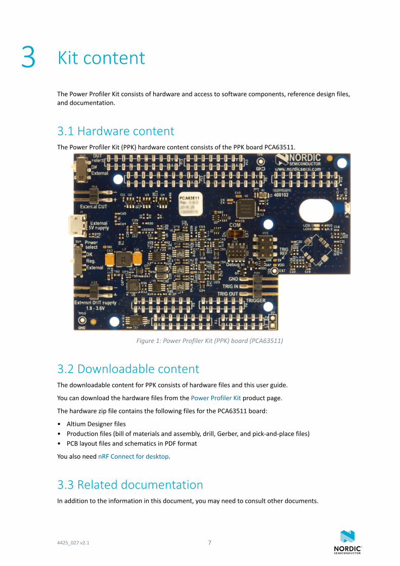
3.1 Hardware contentThe Power Profiler Kit (PPK) hardware content consists of the PPK board PCA63511.
Figure 1: Power Profiler Kit (PPK) board (PCA63511)
3.2 Downloadable contentThe downloadable content for PPK consists of hardware files and this user guide.
You can download the hardware files from the Power Profiler Kit product page.
The hardware zip file contains the following files for the PCA63511 board:
• Altium Designer files• Production files (bill of materials and assembly, drill, Gerber, and pick-and-place files)• PCB layout files and schematics in PDF format
You also need nRF Connect for desktop.
3.3 Related documentationIn addition to the information in this document, you may need to consult other documents.
4425_027 v2.1 7
Kit content
Nordic documentation• nRF51 Development Kit• nRF52 Development Kit• nRF52840 Preview Development Kit
4425_027 v2.1 8
4 Quick start
Complete a few steps to set up your Power Profiler Kit (PPK). In the simplest configuration, the PPK isconnected to an nRF5x Development Kit (DK, not included in the package).
In this quick start, the PPK measures current on the nRF5x DK device, which also acts as a power supplyand sends data to the Power Profiler application.
See Nordic Semiconductor Infocenter for information on the nRF51 Series and nRF52 Series.
Complete the following steps:
1. Prepare the nRF5x DK for current measurements by cutting the nRF current measurement solderbridge.For more details, see:
• Section Preparing the development kit board in nRF51 Development Kit User Guide• Preparing the development kit board in nRF52 DK User Guide• Preparing the development kit board in nRF52840 PDK User Guide
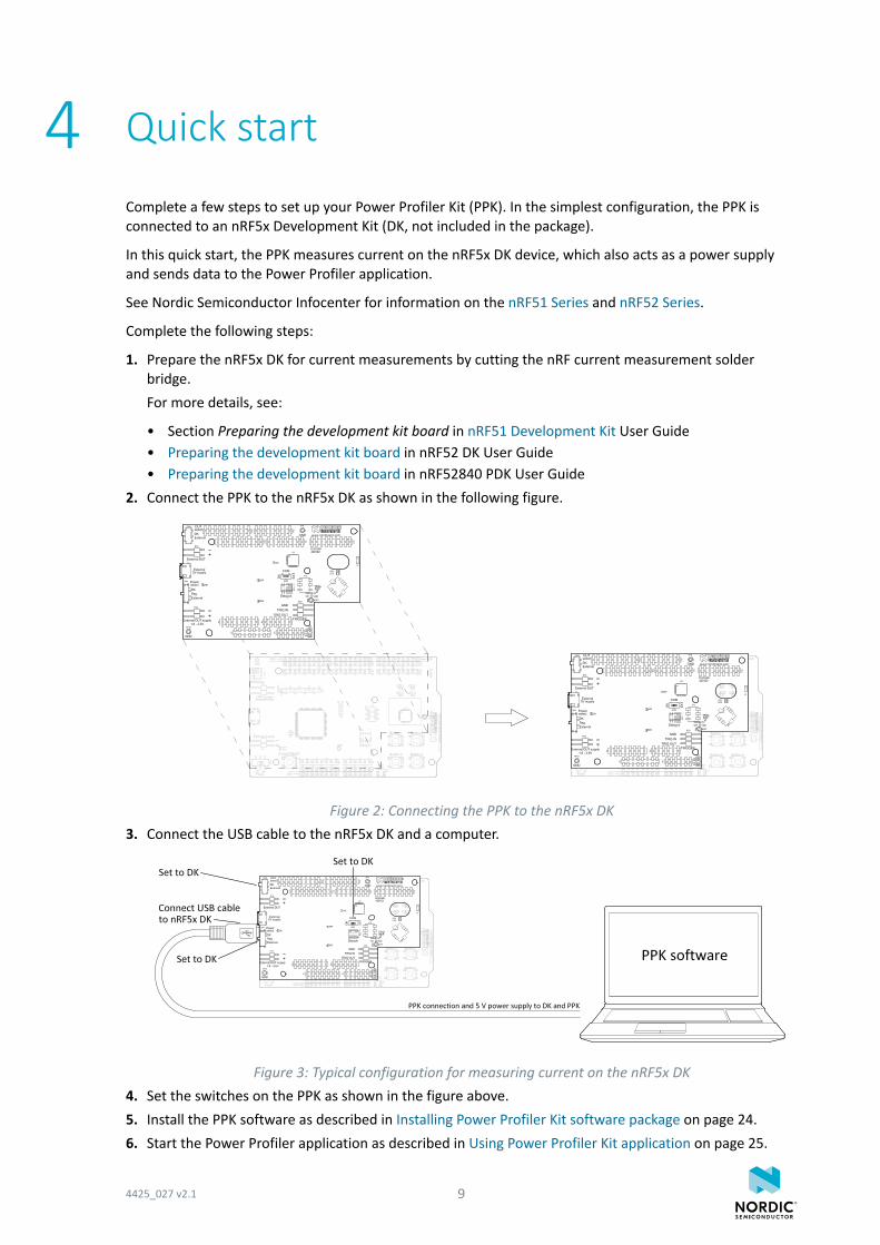
2. Connect the PPK to the nRF5x DK as shown in the following figure.
Figure 2: Connecting the PPK to the nRF5x DK3. Connect the USB cable to the nRF5x DK and a computer.
Figure 3: Typical configuration for measuring current on the nRF5x DK4. Set the switches on the PPK as shown in the figure above.5. Install the PPK software as described in Installing Power Profiler Kit software package on page 24.6. Start the Power Profiler application as described in Using Power Profiler Kit application on page 25.
4425_027 v2.1 9

Quick start
The PPK is ready to use.
4425_027 v2.1 10
5 Power Profiler Kit overview
The Power Profiler Kit (PPK) contains both hardware and software components.
5.1 Measurement systemThe PPK is driven by the nRF52832 SoC, which uses its ADC (analog-to-digital converter) to measure avoltage drop over a series of measurement resistors. Resistor values are used to calculate the powerconsumption. The PPK has three different measurement ranges, which are managed by an automaticswitch circuitry.
To send the data to the desktop application, the nRF52832 SoC on the PPK uses the SEGGER RTT (Real-Time Transfer). By connecting the PPK to an nRF5x DK, the SEGGER J-Link debug probe available on thenRF5x DK can be used for the computer connection. Alternatively, an external SEGGER J-Link debugger canbe used.
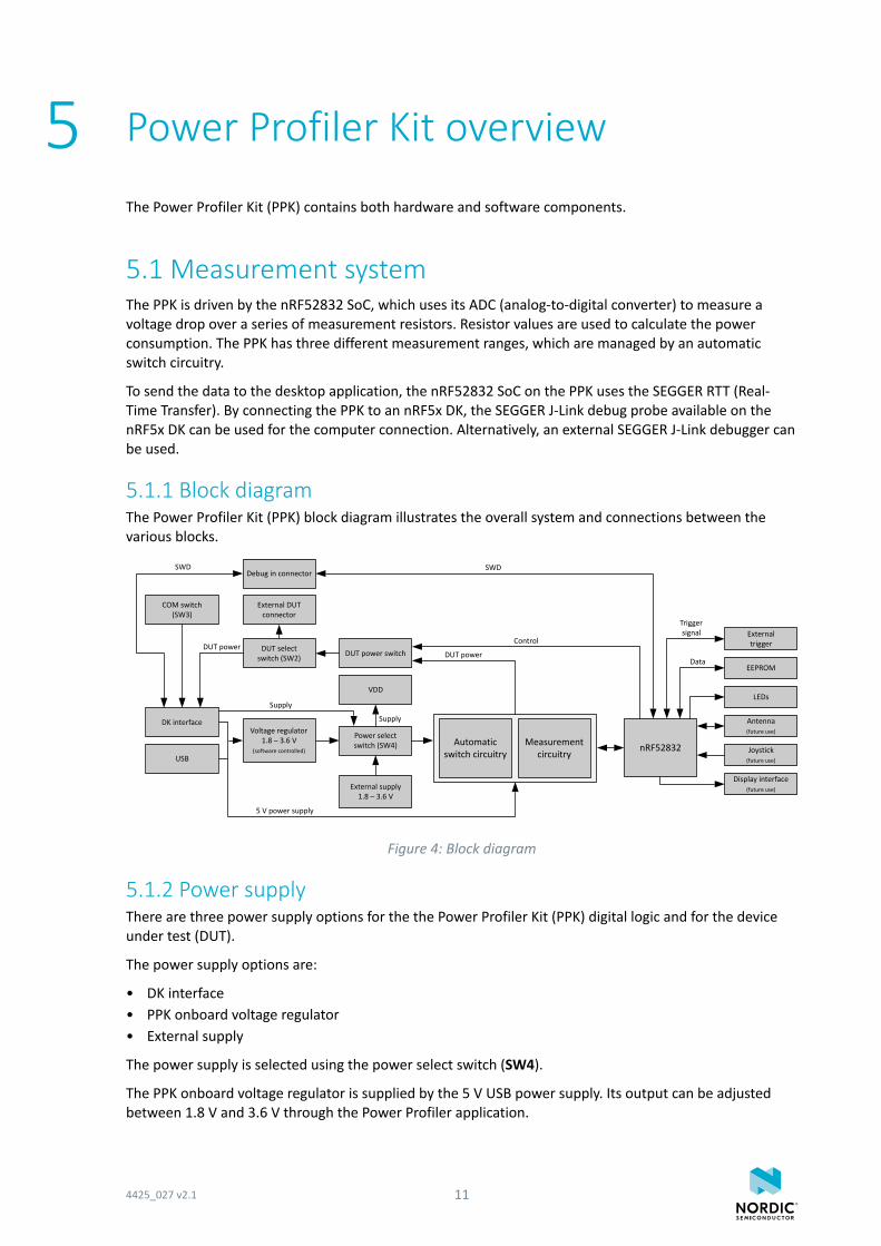
5.1.1 Block diagramThe Power Profiler Kit (PPK) block diagram illustrates the overall system and connections between thevarious blocks.
Joystick (future use)
LEDs
Antenna (future use)
nRF52832Automatic switch circuitry
DUT power switch
EEPROM
External trigger
Power select switch (SW4)
Voltage regulator 1.8 – 3.6 V
(software controlled)
Debug in connector
DK interface
USB
External supply 1.8 – 3.6 V
DUT select switch (SW2)
External DUT connector
Display interface (future use)
COM switch (SW3)
Measurement circuitry
Data
Trigger signal
SWD
ControlDUT power
SWD
DUT power
Supply
5 V power supply
VDD
Supply
Figure 4: Block diagram
5.1.2 Power supplyThere are three power supply options for the the Power Profiler Kit (PPK) digital logic and for the deviceunder test (DUT).
The power supply options are:
• DK interface• PPK onboard voltage regulator• External supply
The power supply is selected using the power select switch (SW4).
The PPK onboard voltage regulator is supplied by the 5 V USB power supply. Its output can be adjustedbetween 1.8 V and 3.6 V through the Power Profiler application.
4425_027 v2.1 11
Power Profiler Kit overview
If an external power supply is used, the voltage is applied directly to the circuits without regulation. Thisvoltage must be limited to the 1.8–3.6 V range.
When the DK is selected as the power supply, the DK supplies the PPK circuitry.
The analog part of the automatic switch circuitry requires a 5 V power supply. When the PPK is connectedto an nRF5x DK, the 5 V is supplied by the DK. When the PPK is used standalone, a USB cable has to beconnected to supply the 5 V required by the circuitry.
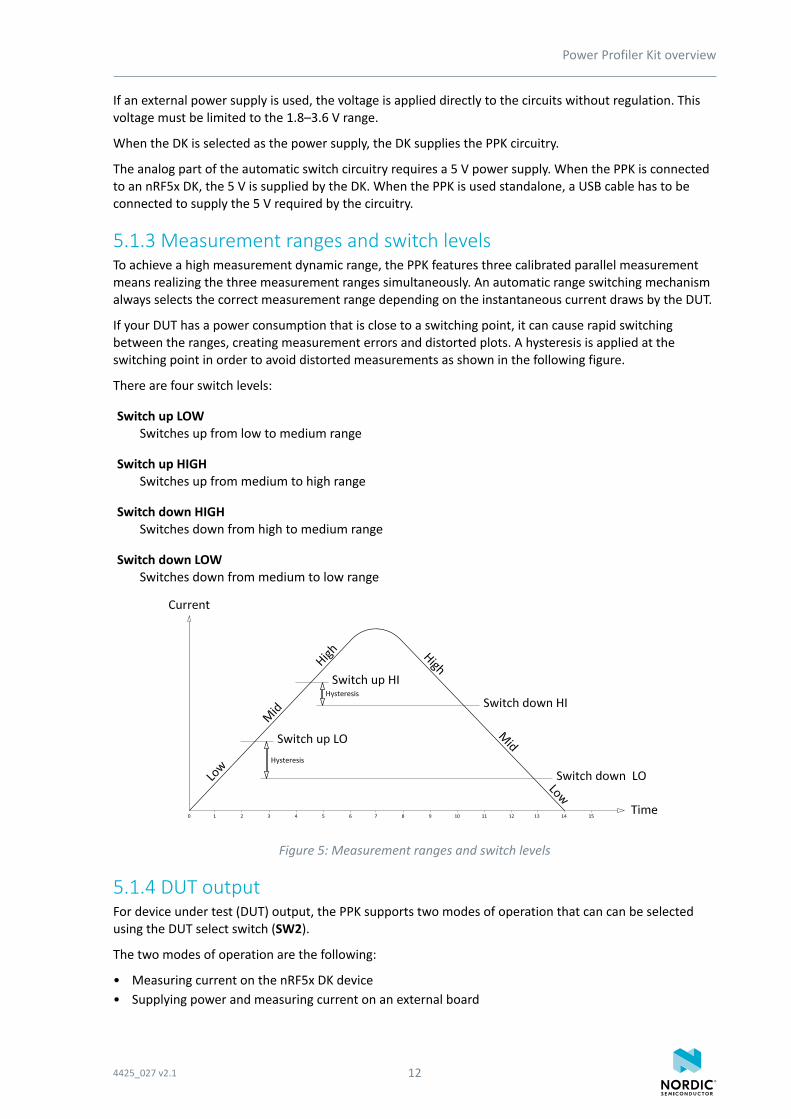
5.1.3 Measurement ranges and switch levelsTo achieve a high measurement dynamic range, the PPK features three calibrated parallel measurementmeans realizing the three measurement ranges simultaneously. An automatic range switching mechanismalways selects the correct measurement range depending on the instantaneous current draws by the DUT.
If your DUT has a power consumption that is close to a switching point, it can cause rapid switchingbetween the ranges, creating measurement errors and distorted plots. A hysteresis is applied at theswitching point in order to avoid distorted measurements as shown in the following figure.
There are four switch levels:
Switch up LOWSwitches up from low to medium range
Switch up HIGHSwitches up from medium to high range
Switch down HIGHSwitches down from high to medium range
Switch down LOWSwitches down from medium to low range
Figure 5: Measurement ranges and switch levels
5.1.4 DUT outputFor device under test (DUT) output, the PPK supports two modes of operation that can can be selectedusing the DUT select switch (SW2).
The two modes of operation are the following:
• Measuring current on the nRF5x DK device• Supplying power and measuring current on an external board
4425_027 v2.1 12
Power Profiler Kit overview
The DUT can be turned on and off using the power switch (Power OFF) in the Power Profiler application.See Figure 15: Settings and Plots view in the Power Profiler application on page 25.
5.1.5 EEPROMOn the PPK, there is an EEPROM memory connected to the nRF52832 SoC. The EEPROM is used to storecalibration data.
5.1.6 Display interface and joystickReserved for future use.
5.2 ConnectorsAccess to the Power Profiler Kit (PPK) is available from a set of connectors.
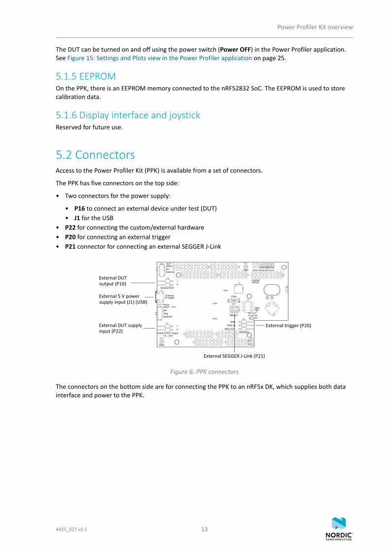
The PPK has five connectors on the top side:
• Two connectors for the power supply:
• P16 to connect an external device under test (DUT)• J1 for the USB
• P22 for connecting the custom/external hardware• P20 for connecting an external trigger• P21 connector for connecting an external SEGGER J-Link
Figure 6: PPK connectors
The connectors on the bottom side are for connecting the PPK to an nRF5x DK, which supplies both datainterface and power to the PPK.
4425_027 v2.1 13
Power Profiler Kit overview
Connector Description
External 5 V power supply input(USB; J1)
This USB connector on the PPK supplies the onboard analogmeasurement circuitry and the onboard regulator with 5 Vprovided by a USB host.
This connector is used when the PPK is used standalone or anytime the USB on the nRF5x DK is not connected.
Note: When used with an nRF5x DK with USB connection,this connector must not be used.
External DUT output (P16) The External DUT connector provides power to the DUT.
External DUT supply input (P22) A lab power supply from 1.8 to 3.6 V can be connected here toprovide precise control of the voltage.
External trigger (P20) This connector allows you to:
• Feed an external trigger to the PPK (15 V max)• Have the PPK send a trigger signal to external instruments
The voltage of the TRIG OUT pin can be configured by the TRIG REFon the PPK board which has the following options:
• VDD: default• 5 V: cut SB7 and solder SB8• External voltage: cut SB7 and SB8 (if shorted) and connect to
TP5 (EXT)
External SEGGER J-Link (P21) Used to connect an external SEGGER J-Link for communicating withthe desktop application when:
• The PPK is used standalone• The SEGGER J-Link on the nRF5x DK is used for debugging of the
nRF5x chip on the DK
If this connector is in use and the PPK is connected to an nRF5xDK board, the COM switch (SW3) must be in the "EXT" positionto disconnect the PPK from the SEGGER J-Link on the DK. Howto connect and use is described in Table 2: PPK switches on page15.
Table 1: PPK connectors
5.3 SwitchesThe Power Profiler Kit (PPK) has three switches: One for selecting the device under test (DUT) on whichcurrent is measured, one for the power supply, and one for the SEGGER J-Link connection.
4425_027 v2.1 14
Power Profiler Kit overview
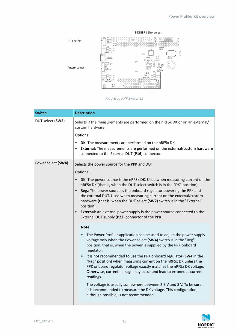
Figure 7: PPK switches
Switch Description
DUT select (SW2) Selects if the measurements are performed on the nRF5x DK or on an external/custom hardware.
Options:
• DK: The measurements are performed on the nRF5x DK.• External: The measurements are performed on the external/custom hardware
connected to the External DUT (P16) connector.
Power select (SW4) Selects the power source for the PPK and DUT.
Options:
• DK: The power source is the nRF5x DK. Used when measuring current on thenRF5x DK (that is, when the DUT select switch is in the "DK" position).
• Reg.: The power source is the onboard regulator powering the PPK andthe external DUT. Used when measuring current on the external/customhardware (that is, when the DUT select (SW2) switch is in the "External"position).
• External: An external power supply is the power source connected to theExternal DUT supply (P22) connector of the PPK.
Note:
• The Power Profiler application can be used to adjust the power supplyvoltage only when the Power select (SW4) switch is in the "Reg"position, that is, when the power is supplied by the PPK onboardregulator.
• It is not recommended to use the PPK onboard regulator (SW4 in the"Reg" position) when measuring current on the nRF5x DK unless thePPK onboard regulator voltage exactly matches the nRF5x DK voltage.Otherwise, current leakage may occur and lead to erroneous currentreadings.
The voltage is usually somewhere between 2.9 V and 3 V. To be sure,it is recommended to measure the DK voltage. This configuration,although possible, is not recommended.
4425_027 v2.1 15
Power Profiler Kit overview
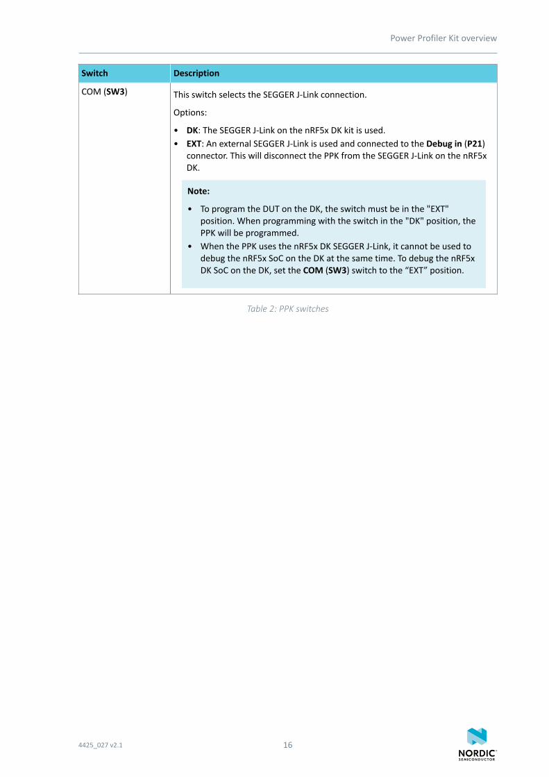
Switch Description
COM (SW3) This switch selects the SEGGER J-Link connection.
Options:
• DK: The SEGGER J-Link on the nRF5x DK kit is used.• EXT: An external SEGGER J-Link is used and connected to the Debug in (P21)
connector. This will disconnect the PPK from the SEGGER J-Link on the nRF5xDK.
Note:
• To program the DUT on the DK, the switch must be in the "EXT"position. When programming with the switch in the "DK" position, thePPK will be programmed.
• When the PPK uses the nRF5x DK SEGGER J-Link, it cannot be used todebug the nRF5x SoC on the DK at the same time. To debug the nRF5xDK SoC on the DK, set the COM (SW3) switch to the “EXT” position.
Table 2: PPK switches
4425_027 v2.1 16
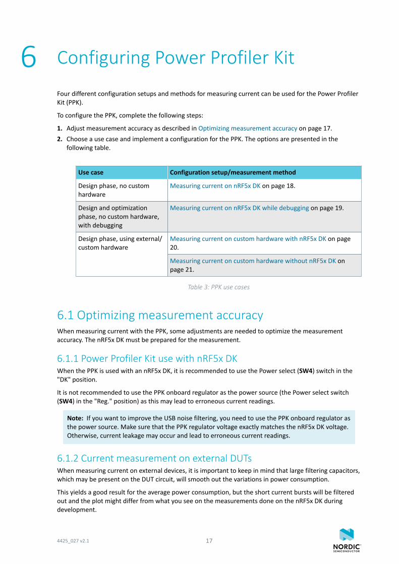
6 Configuring Power Profiler Kit
Four different configuration setups and methods for measuring current can be used for the Power ProfilerKit (PPK).
To configure the PPK, complete the following steps:
1. Adjust measurement accuracy as described in Optimizing measurement accuracy on page 17.2. Choose a use case and implement a configuration for the PPK. The options are presented in the
following table.
Use case Configuration setup/measurement method
Design phase, no customhardware
Measuring current on nRF5x DK on page 18.
Design and optimizationphase, no custom hardware,with debugging
Measuring current on nRF5x DK while debugging on page 19.
Measuring current on custom hardware with nRF5x DK on page20.
Design phase, using external/custom hardware
Measuring current on custom hardware without nRF5x DK onpage 21.
Table 3: PPK use cases
6.1 Optimizing measurement accuracyWhen measuring current with the PPK, some adjustments are needed to optimize the measurementaccuracy. The nRF5x DK must be prepared for the measurement.
6.1.1 Power Profiler Kit use with nRF5x DKWhen the PPK is used with an nRF5x DK, it is recommended to use the Power select (SW4) switch in the"DK" position.
It is not recommended to use the PPK onboard regulator as the power source (the Power select switch(SW4) in the "Reg." position) as this may lead to erroneous current readings.
Note: If you want to improve the USB noise filtering, you need to use the PPK onboard regulator asthe power source. Make sure that the PPK regulator voltage exactly matches the nRF5x DK voltage.Otherwise, current leakage may occur and lead to erroneous current readings.
6.1.2 Current measurement on external DUTsWhen measuring current on external devices, it is important to keep in mind that large filtering capacitors,which may be present on the DUT circuit, will smooth out the variations in power consumption.
This yields a good result for the average power consumption, but the short current bursts will be filteredout and the plot might differ from what you see on the measurements done on the nRF5x DK duringdevelopment.
4425_027 v2.1 17
Configuring Power Profiler Kit
You must include decoupling capacitors to ensure correct operation of the devices. However, as a goodpractice, keep extra decoupling capacitors to a minimum when measuring detailed current draw.
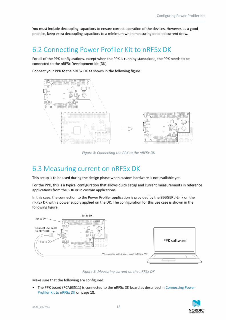
6.2 Connecting Power Profiler Kit to nRF5x DKFor all of the PPK configurations, except when the PPK is running standalone, the PPK needs to beconnected to the nRF5x Development Kit (DK).
Connect your PPK to the nRF5x DK as shown in the following figure.
Figure 8: Connecting the PPK to the nRF5x DK
6.3 Measuring current on nRF5x DKThis setup is to be used during the design phase when custom hardware is not available yet.
For the PPK, this is a typical configuration that allows quick setup and current measurements in referenceapplications from the SDK or in custom applications.
In this case, the connection to the Power Profiler application is provided by the SEGGER J-Link on thenRF5x DK with a power supply applied on the DK. The configuration for this use case is shown in thefollowing figure.
Figure 9: Measuring current on the nRF5x DK
Make sure that the following are configured:
• The PPK board (PCA63511) is connected to the nRF5x DK board as described in Connecting PowerProfiler Kit to nRF5x DK on page 18.
4425_027 v2.1 18
Configuring Power Profiler Kit
• The DUT select switch (SW2) is in the "DK" position.• The Power select switch (SW4) is in the "DK" position.• The COM switch (SW3) is in the "DK" position.• The USB cable is plugged into the USB connector on the nRF5x DK and connected to a computer with
the Power Profiler application.
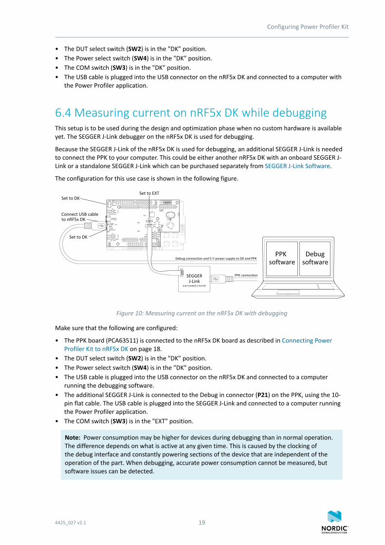
6.4 Measuring current on nRF5x DK while debuggingThis setup is to be used during the design and optimization phase when no custom hardware is availableyet. The SEGGER J-Link debugger on the nRF5x DK is used for debugging.
Because the SEGGER J-Link of the nRF5x DK is used for debugging, an additional SEGGER J-Link is neededto connect the PPK to your computer. This could be either another nRF5x DK with an onboard SEGGER J-Link or a standalone SEGGER J-Link which can be purchased separately from SEGGER J-Link Software.
The configuration for this use case is shown in the following figure.
Figure 10: Measuring current on the nRF5x DK with debugging
Make sure that the following are configured:
• The PPK board (PCA63511) is connected to the nRF5x DK board as described in Connecting PowerProfiler Kit to nRF5x DK on page 18.
• The DUT select switch (SW2) is in the "DK" position.• The Power select switch (SW4) is in the "DK" position.• The USB cable is plugged into the USB connector on the nRF5x DK and connected to a computer
running the debugging software.• The additional SEGGER J-Link is connected to the Debug in connector (P21) on the PPK, using the 10-
pin flat cable. The USB cable is plugged into the SEGGER J-Link and connected to a computer runningthe Power Profiler application.
• The COM switch (SW3) is in the "EXT" position.
Note: Power consumption may be higher for devices during debugging than in normal operation.The difference depends on what is active at any given time. This is caused by the clocking ofthe debug interface and constantly powering sections of the device that are independent of theoperation of the part. When debugging, accurate power consumption cannot be measured, butsoftware issues can be detected.
4425_027 v2.1 19
Configuring Power Profiler Kit
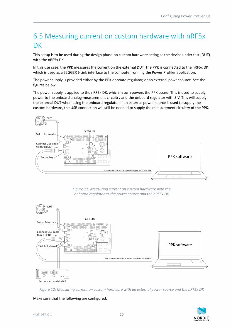
6.5 Measuring current on custom hardware with nRF5xDKThis setup is to be used during the design phase on custom hardware acting as the device under test (DUT)with the nRF5x DK.
In this use case, the PPK measures the current on the external DUT. The PPK is connected to the nRF5x DKwhich is used as a SEGGER J-Link interface to the computer running the Power Profiler application.
The power supply is provided either by the PPK onboard regulator, or an external power source. See thefigures below.
The power supply is applied to the nRF5x DK, which in turn powers the PPK board. This is used to supplypower to the onboard analog measurement circuitry and the onboard regulator with 5 V. This will supplythe external DUT when using the onboard regulator. If an external power source is used to supply thecustom hardware, the USB connection will still be needed to supply the measurement circuitry of the PPK.
Figure 11: Measuring current on custom hardware with theonboard regulator as the power source and the nRF5x DK
Figure 12: Measuring current on custom hardware with an external power source and the nRF5x DK
Make sure that the following are configured:
4425_027 v2.1 20
Configuring Power Profiler Kit
• The PPK board (PCA63511) is connected to the nRF5x DK board as described in Connecting PowerProfiler Kit to nRF5x DK on page 18.
• The USB cable is plugged into the USB connector on the nRF5x DK and connected to a computerrunning the Power Profiler application.
• The DUT select switch (SW2) is in the "External" position.• The custom hardware is connected to the External DUT connector (P16) of the PPK.• The power source is one of the following:
• The PPK onboard regulator: Set the Power select switch (SW4) in the "Reg" position.• External power supply: In addition to the USB cable plugged into the nRF5x DK, make sure that the
external power is connected to the External DUT supply connector (P22) of the PPK (voltage rangefrom 1.8 V to 3.6 V). Set the Power select switch (SW4) in the "External" position.
• The COM switch (SW3) is in the "DK" position.
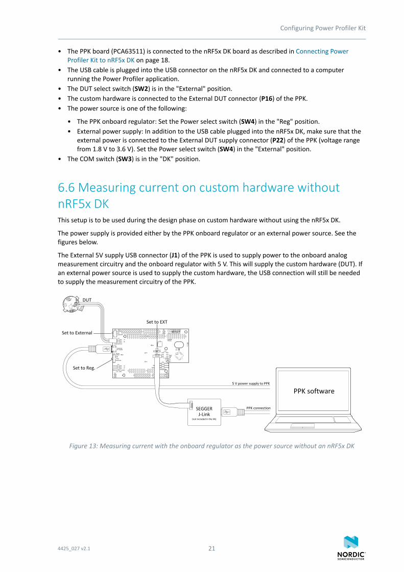
6.6 Measuring current on custom hardware withoutnRF5x DKThis setup is to be used during the design phase on custom hardware without using the nRF5x DK.
The power supply is provided either by the PPK onboard regulator or an external power source. See thefigures below.
The External 5V supply USB connector (J1) of the PPK is used to supply power to the onboard analogmeasurement circuitry and the onboard regulator with 5 V. This will supply the custom hardware (DUT). Ifan external power source is used to supply the custom hardware, the USB connection will still be neededto supply the measurement circuitry of the PPK.
Figure 13: Measuring current with the onboard regulator as the power source without an nRF5x DK
4425_027 v2.1 21
Configuring Power Profiler Kit
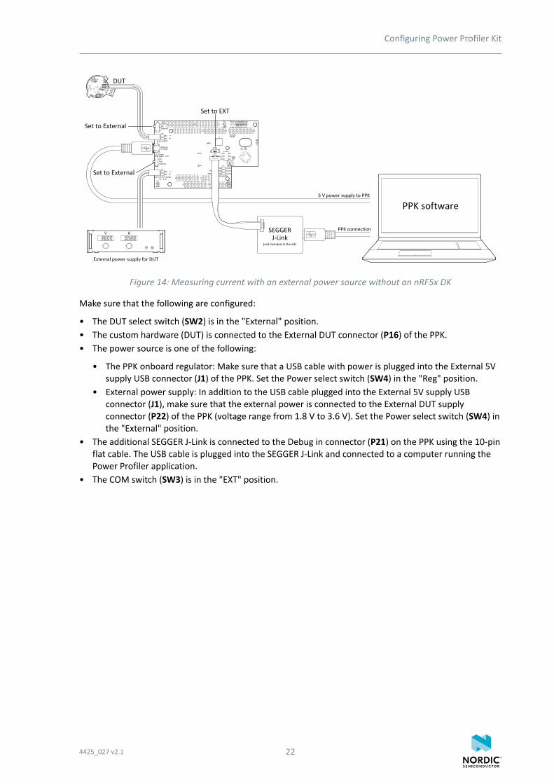
Figure 14: Measuring current with an external power source without an nRF5x DK
Make sure that the following are configured:
• The DUT select switch (SW2) is in the "External" position.• The custom hardware (DUT) is connected to the External DUT connector (P16) of the PPK.• The power source is one of the following:
• The PPK onboard regulator: Make sure that a USB cable with power is plugged into the External 5Vsupply USB connector (J1) of the PPK. Set the Power select switch (SW4) in the "Reg" position.
• External power supply: In addition to the USB cable plugged into the External 5V supply USBconnector (J1), make sure that the external power is connected to the External DUT supplyconnector (P22) of the PPK (voltage range from 1.8 V to 3.6 V). Set the Power select switch (SW4) inthe "External" position.
• The additional SEGGER J-Link is connected to the Debug in connector (P21) on the PPK using the 10-pinflat cable. The USB cable is plugged into the SEGGER J-Link and connected to a computer running thePower Profiler application.
• The COM switch (SW3) is in the "EXT" position.
4425_027 v2.1 22
7 Connecting Power Profiler Kit to acomputer
You need to connect the Power Profiler Kit (PPK) to a computer with a USB cable in order to use it.
1. Connect the PPK to your computer using a USB cable.
• If the PPK is connected to an nRF5x DK, connect the USB cable to the nRF5x DK.• If the PPK is running standalone, connect the USB cable to the PPK (J1). See Figure 6: PPK
connectors on page 13.2. If you are using an external SEGGER J-Link in your configuration, use a USB cable to connect it to your
computer.3. If you are using the nRF5x DK, slide the nRF5x power switch to "ON".
If Windows driver installation starts for the inserted DK, wait until it finishes before continuing.4. Verify that the LED2 is lit on the PPK.
Your PPK is now connected to the computer. You are ready to start the Power Profiler application.
4425_027 v2.1 23
8 Installing Power Profiler Kit softwarepackage
The Power Profiler Kit (PPK) software package is installed using nRF Connect.
Before you start, check Minimum requirements on page 6.
1. Open nRF Connect.2. Click Add/remove apps.3. Click Install.
For information about using the software, see Using Power Profiler Kit application on page 25.
4425_027 v2.1 24
9 Using Power Profiler Kit application
The Power Profiler Kit (PPK) must be configured correctly, connected to your computer, and poweredbefore the Power Profiler application can be started.
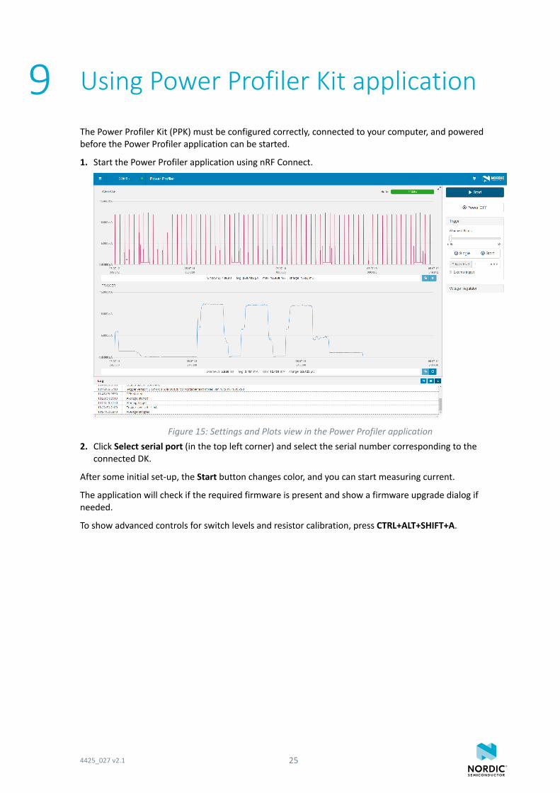
1. Start the Power Profiler application using nRF Connect.
Figure 15: Settings and Plots view in the Power Profiler application2. Click Select serial port (in the top left corner) and select the serial number corresponding to the
connected DK.
After some initial set-up, the Start button changes color, and you can start measuring current.
The application will check if the required firmware is present and show a firmware upgrade dialog ifneeded.
To show advanced controls for switch levels and resistor calibration, press CTRL+ALT+SHIFT+A.
4425_027 v2.1 25
10 Electrical specifications
These specifications contain the property values that are essential for using the Power Profiler Kit (PPK).
10.1 Environmental specificationsThese environmental specifications contain the values that are essential for using the Power Profiler Kit(PPK).
Item Name Min Typ Max Unit Description
Operatingtemperature
Op_Temp 15 30 °C
Table 4: Environmental specifications
10.2 Power supply specificationsThese power supply values are essential for using the Power Profiler Kit (PPK).
Item Name Min Typ Max Unit Description
DUT voltage VDD_DUT 1.8 3.6 V
External supplyvoltage
VDD_EXT 1.8 3.6 V
Micro-USBsupply voltage
V5V 4.5 5.5 V USB voltagetolerances
Table 5: Power supply specifications
10.3 Measurement specificationsThese measurement specifications contain the property values that are essential for using the PowerProfiler Kit (PPK).
10.3.1 Maximum DUT admissible currentThe maximum DUT admissible current specification contains the value that is essential for using the PowerProfiler Kit (PPK).
Item Name Min Typ Max Unit Description
Maximum DUTadmissiblecurrent
Max_I 70 mA
Table 6: Maximum DUT admissible current
4425_027 v2.1 26
Electrical specifications
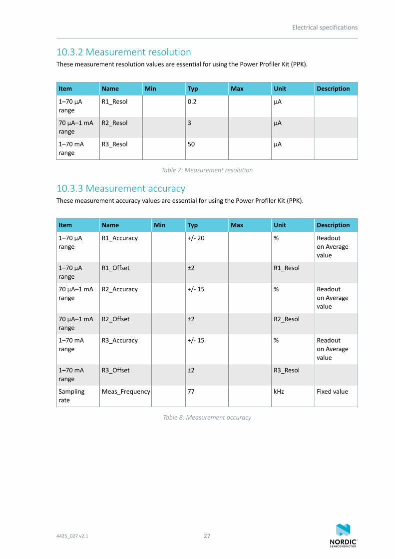
10.3.2 Measurement resolutionThese measurement resolution values are essential for using the Power Profiler Kit (PPK).
Item Name Min Typ Max Unit Description
1–70 µArange
R1_Resol 0.2 µA
70 µA–1 mArange
R2_Resol 3 µA
1–70 mArange
R3_Resol 50 µA
Table 7: Measurement resolution
10.3.3 Measurement accuracyThese measurement accuracy values are essential for using the Power Profiler Kit (PPK).
Item Name Min Typ Max Unit Description
1–70 µArange
R1_Accuracy +/- 20 % Readouton Averagevalue
1–70 µArange
R1_Offset ±2 R1_Resol
70 µA–1 mArange
R2_Accuracy +/- 15 % Readouton Averagevalue
70 µA–1 mArange
R2_Offset ±2 R2_Resol
1–70 mArange
R3_Accuracy +/- 15 % Readouton Averagevalue
1–70 mArange
R3_Offset ±2 R3_Resol
Samplingrate
Meas_Frequency 77 kHz Fixed value
Table 8: Measurement accuracy
4425_027 v2.1 27
11 Troubleshooting
Here are some basic troubleshooting steps to help you fix issues you may encounter when using the PowerProfiler Kit (PPK).
PPK only measuring noise
Make sure you have prepared the nRF5x DK for current measurements by cutting the nRF currentmeasurement solder bridge as described in:
• Section Preparing the development kit board in nRF51 Development Kit User Guide• Preparing the development kit board in nRF52 DK User Guide• Preparing the development kit board in nRF52840 PDK User Guide
Measurements fluctuate when there should be a steady current drawYour DUT may have a power consumption that is close to a switching point causing rapid switchingbetween the ranges and creating measurement errors/distorted plots. Try adjusting the switchingpoints.
The graph response is very slowAvoid using USB hubs and docking stations. Also, if the trigger window is receiving a lot of updates,consider stopping this plot to have better throughput for the Average plot.
For more information, visit Nordic Developer Zone.
For personalized support from our technical support team, sign up for or sign in to Nordic Developer Zoneand enter a private ticket.
4425_027 v2.1 28
Legal noticesBy using this documentation you agree to our terms and conditions of use. Nordic Semiconductor maychange these terms and conditions at any time without notice.
Liability disclaimerNordic Semiconductor ASA reserves the right to make changes without further notice to the product toimprove reliability, function or design. Nordic Semiconductor ASA does not assume any liability arising outof the application or use of any product or circuits described herein.
All information contained in this document represents information on the product at the time ofpublication. Nordic Semiconductor ASA reserves the right to make corrections, enhancements, and otherchanges to this document without notice. While Nordic Semiconductor ASA has used reasonable carein preparing the information included in this document, it may contain technical or other inaccuracies,omissions and typographical errors. Nordic Semiconductor ASA assumes no liability whatsoever for anydamages incurred by you resulting from errors in or omissions from the information included herein.
Life support applicationsNordic Semiconductor products are not designed for use in life support appliances, devices, or systemswhere malfunction of these products can reasonably be expected to result in personal injury.
Nordic Semiconductor ASA customers using or selling these products for use in such applications do soat their own risk and agree to fully indemnify Nordic Semiconductor ASA for any damages resulting fromsuch improper use or sale.
RoHS and REACH statementNordic Semiconductor products meet the requirements of Directive 2011/65/EU of the EuropeanParliament and of the Council on the Restriction of Hazardous Substances (RoHS 2) and the requirementsof the REACH regulation (EC 1907/2006) on Registration, Evaluation, Authorization and Restriction ofChemicals.
The SVHC (Substances of Very High Concern) candidate list is continually being updated. Completehazardous substance reports, material composition reports and latest version of Nordic's REACHstatement can be found on our website www.nordicsemi.com.
TrademarksAll trademarks, service marks, trade names, product names and logos appearing in this documentation arethe property of their respective owners.
Copyright notice© 2018 Nordic Semiconductor ASA. All rights are reserved. Reproduction in whole or in part is prohibitedwithout the prior written permission of the copyright holder.
4425_027 v2.1 29


![Novak Super Duty XR Manual - CompetitionX · POWER CAPACITORS [Novak kit #5675] An external power capacitor is installed, and MUST BE USED to maintain cool and smooth operation. Refer](https://static.fdocument.org/doc/165x107/5e2fb8c02441df018b2f2b1b/novak-super-duty-xr-manual-competitionx-power-capacitors-novak-kit-5675-an.jpg)