
Positron Emission · r A t t e n u a t i o n C o e f f i c i e n t (c m-1) Newborn 1 YO 5 YO 10 YO...
16
1 Basic Physics of PET and PET/CT Frederic H. Fahey DSc Children’s Hospital Boston Harvard Medical School [email protected] Outline • Basics of PET Scanner Design • Data Acquisition • Scintillation Materials • Reconstruction Methods • PET/CT • Time-of-Flight (TOF) PET • MicroPET Positron Emission 18 F 511 keV 511 keV + e- Detector Ring
Transcript of Positron Emission · r A t t e n u a t i o n C o e f f i c i e n t (c m-1) Newborn 1 YO 5 YO 10 YO...
1
BasicPhysics of PET andPET/CT
FredericH. FaheyDSc
Children’s Hospital BostonHarvardMedical School
Outline
• Basicsof PETScannerDesign
• Data Acquisition
• Scintillation Materials
• Reconstruction Methods
• PET/CT
• Time-of-Flight (TOF) PET
• MicroPET
Positron Emission18F
511keV
511keVβ+
e-
DetectorRing
2
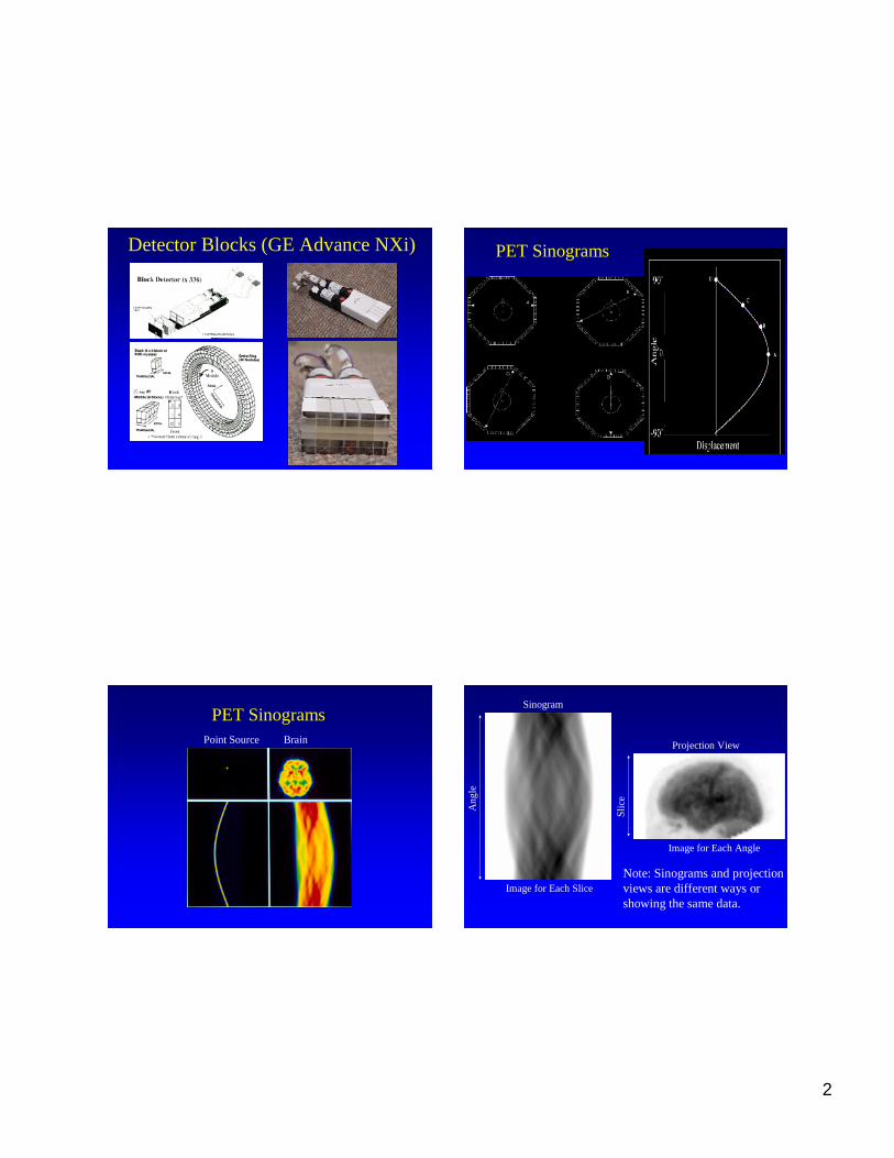
Detector Blocks(GE AdvanceNXi) PET Sinograms
PointSource Brain
PET SinogramsSinogram
Imagefor Each Slice
Ang
le
Imagefor Each Angle
Projection View
Slic
e
Note: Sinogramsandprojectionviewsaredifferent waysorshowingthesamedata.
3
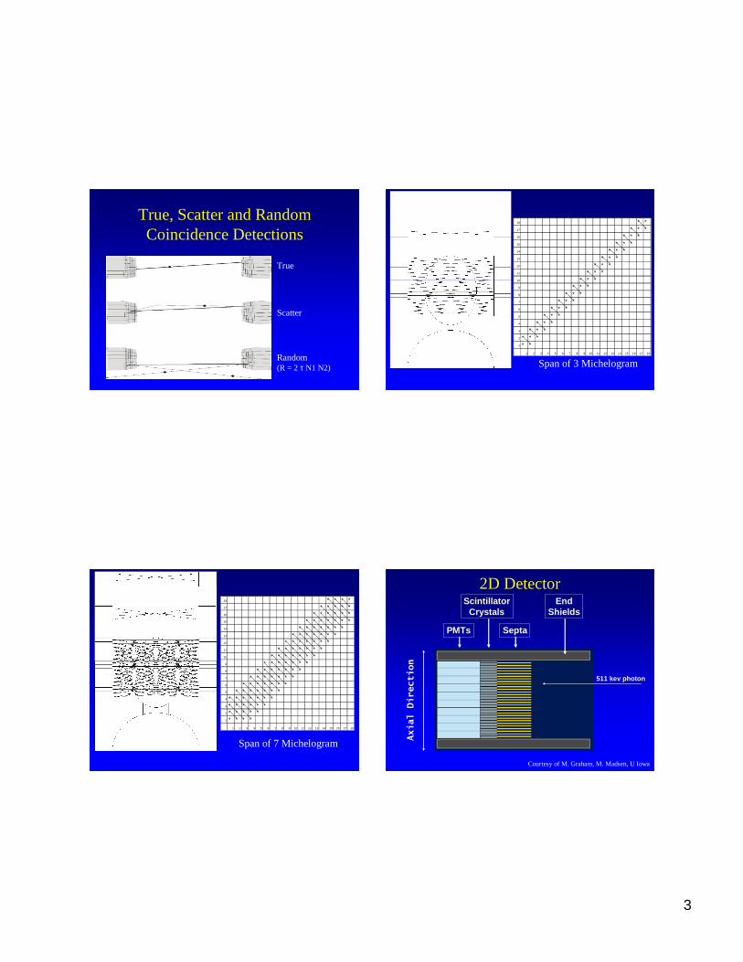
True, ScatterandRandomCoincidence Detections
True
Random
Scatter
(R = 2 τ N1 N2)
18 * *17 * * *16 * * *15 * * *14 * * *13 * * *12 * * *11 * * *10 * * *
9 * * *8 * * *7 * * *6 * * *5 * * *4 * * *3 * * *2 * * *1 * *
1 2 3 4 5 6 7 8 9 10 11 12 13 14 15 16 17 18
Spanof 3 Michelogram
18 * * * *17 * * * * *16 * * * * * *15 * * * * * * *14 * * * * * * *13 * * * * * * *12 * * * * * * *11 * * * * * * *10 * * * * * * *
9 * * * * * * *8 * * * * * * *7 * * * * * * *6 * * * * * * *5 * * * * * * *4 * * * * * * *3 * * * * * *2 * * * * *1 * * * *
1 2 3 4 5 6 7 8 9 10 11 12 13 14 15 16 17 18
Spanof 7 Michelogram
2D Detector
PMTs
ScintillatorCrys tals
Septa
EndShields
511 kev photon
Axial
Direction
Courtesyof M. Graham,M. Madsen,U Iowa

4
AcquisitionModes
2D
3Dseptaare
removed
16 * * * * * * * * * * * * * * * *15 * * * * * * * * * * * * * * * *14 * * * * * * * * * * * * * * * *13 * * * * * * * * * * * * * * * *12 * * * * * * * * * * * * * * * *11 * * * * * * * * * * * * * * * *10 * * * * * * * * * * * * * * * *
9 * * * * * * * * * * * * * * * *8 * * * * * * * * * * * * * * * *7 * * * * * * * * * * * * * * * *6 * * * * * * * * * * * * * * * *5 * * * * * * * * * * * * * * * *4 * * * * * * * * * * * * * * * *3 * * * * * * * * * * * * * * * *2 * * * * * * * * * * * * * * * *1 * * * * * * * * * * * * * * * *
1 2 3 4 5 6 7 8 9 10 11 12 13 14 15 16
Segment1
Segment 2
Segment 3
18 * * * * * * * * * * * *17 * * * * * * * * * * * * *16 * * * * * * * * * * * * * *15 * * * * * * * * * * * * * * *14 * * * * * * * * * * * * * * * *13 * * * * * * * * * * * * * * * * *12 * * * * * * * * * * * * * * * * * *11 * * * * * * * * * * * * * * * * * *10 * * * * * * * * * * * * * * * * * *
9 * * * * * * * * * * * * * * * * * *8 * * * * * * * * * * * * * * * * * *7 * * * * * * * * * * * * * * * * * *6 * * * * * * * * * * * * * * * * *5 * * * * * * * * * * * * * * * *4 * * * * * * * * * * * * * * *3 * * * * * * * * * * * * * *2 * * * * * * * * * * * * *1 * * * * * * * * * * * *
1 2 3 4 5 6 7 8 9 10 11 12 13 14 15 16 17 18
1
2
3
4
5
6
7
8
9
10
11
GE 3D Projection view and Michelogram3D PET
• Sensitivi ty dropsoff towardsedges
• 4-5X increased sensitivityoverall
• Increasedscatter (15%to 40%)
• Increasedrandomsfrom out-of-field activity
• Rebinning algorithmsto apply2Dreconstruction
• Somedevices canacquirein 2D or 3D whereassomecanonly acquirein 3D
• 3D in Brain, 2D (or 3D) in WholeBody

5
Criteriafor Scintillation Material
• Detection Efficiency (StoppingPower)– High Effective Z– High Density
• Light Output– Goodenergy resolution– Goodcrystal identifi cation
• Decay Time– Reductionof randomcoincidences– Time-of-Flight PET
CrystalIdentification
SCINTILLATOR NaI(Tl) BGO LSO GSO
Rel. Light Output 100 15-20 75 20-25
PeakWavelength (nm) 410 480 420 440
DecayConstant(ns) 230 300 12,42 30-60
Density(g/mL) 3.67 7.13 7.40 6.71
Effective Z 51 75 66 59
Indexof Refraction 1.85 2.15 1.82 1.85
Hygroscopic? Yes No No No
New Detector Materials Feedback Loop
Backprojection
SimulatedProjections
ActualProjections
Compare
Usetoimprovecurrentestimate
Current Estimate
Err or
Courtesy of JeroldW. Wallis, M.D.

6
Maximum LikelihoodReconstruct ion (ML -EM)
• Maximizethelikelihoodthattheestimatedactivity distribution in thebody(thereconstructed transaxialslices)would leadto themeasured projections
• Usetheexpectation maximization(EM)algorithm to iteratively estimate theactivitydistribution
pixelj
projection bini
aij is theprobabilitythat a photonemittedfrom pixelj isdetectedatprojectionbini.
EM-ML Reconstruction
• aij can contain physical information(effectsof spatialresolution,scatter, attenuation…)
• EM-ML algorithm takesinto accountthenatureof thenoise(quantummottle)in theprojectiondata
• Canyield a moreaccuratereconstruction
λ’ (k)j = λ’ (k -1)j Σ [aij { d/ Σ [aij] λ’ (k -1)j } ]Σ [aij]
λ’ (k)j is thenewestestimateof theobjectpixel value
λ’ (k -1)j is estimateof theobject at last iteration
d is theprojection data
d’ = Σ [aij] λ’ (k -1)j is thecalculated projection data
ML-EM Algorithm

7
λ’ (k)j = λ’ (k -1)j Σ [aij {d/ (Σ [aij] λ’ (k -1)j+acj(rj nj + cj) } ]Σ [aij/nj acj]
acis photonattenuation data
r is randomdata
n is normalization data
c is scatter data
ML-EM Algorithm (addedcorrections)Advantagesof Iterative Reconstruction
• Correct physicscanbeincluded in thereconstruction andPoissionstatistics
• Attenuationcorrection
• Reduction of streak artifact
• Overall quality
Courtesyof SiemensMedical Solutions
Accuratecharacterizationofthepoint spreadfunctions(PSFs) throughout thefilesofview allowsfor anaccurateestimationof the“aij” matrixleading to improvementinspatial resolution andsignal-to-noise.
Courtesyof SiemensMedical Solutions
FBP HD
ImprovedImageQuality with AccurateSpecificationOf thePSFThroughouttheField of View
8
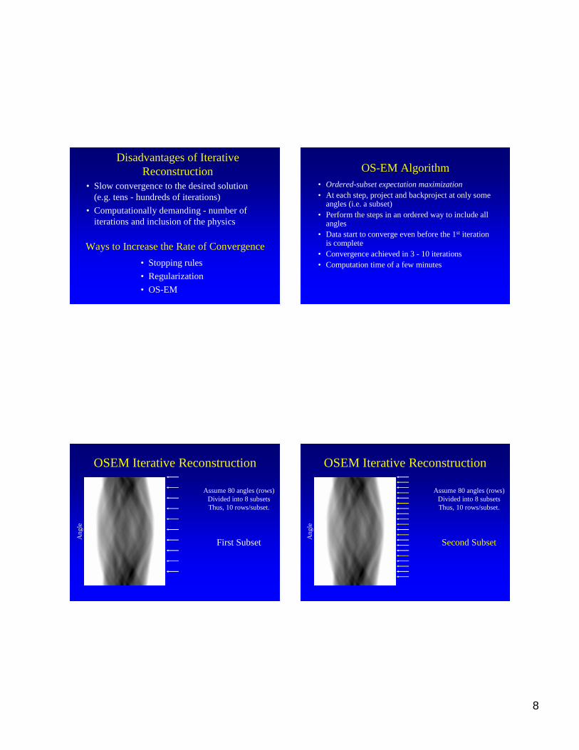
Disadvantagesof IterativeReconstruction
• Slow convergenceto thedesired solution(e.g. tens- hundredsof iterations)
• Computationally demanding- numberofiterationsand inclusionof thephysics
Waysto Increase theRateof Convergence
• Stoppingrules
• Regularization
• OS-EM
OS-EM Algorithm• Ordered-subsetexpectation maximization• At eachstep,project andbackprojectat only some
angles(i.e. a subset)• Performthestepsin anordered way to includeall
angles• Datastart to convergeevenbefore the1st iteration
is complete• Convergenceachievedin 3 - 10 iterations• Computationtime of a few minutes
OSEM IterativeReconstruction
Ang
le
Assume80 angles(rows)Divided into 8 subsetsThus,10 rows/subset.
First Subset
OSEM IterativeReconstruction
Ang
le
Assume80 angles(rows)Divided into 8 subsetsThus, 10 rows/subset.
SecondSubset

9
OSEM IterativeReconstruction
Ang
le
Assume80 angles(rows)Divided into 8 subsetsThus,10 rows/subset.
Third Subset
By thetimeone hasprocessedall of the
projections(rows)once,theestimateof theobjecthasbeenupdated8 times.
OSEM IterativeReconstruction
• FilteredBack-Projection– Fast
– Robust
– Subjectto noise& streaks
• OSEM– Almost asfast
– Handlesnoise& streaks
Example: 28 subsets(12projectionsper subset)and2 iterations)
Single Slice Rebinning (SSRB) FourierRebinning
• More accurate approachto rebinning
• Better estimate of determininginto whichparallelplaneobliquedatashouldbeplaced
• Based on thefrequency-distancerelationship(Valueof Fouriertransformofa sinogramreceivescontributionsmainlyfrom sources at a fixed distancet=-k/ω)
10
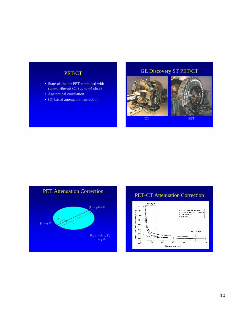
PET/CT
• State-of-the-art PETcombinedwithstate-of-the-art CT (up to 64 slice)
• Anatomical correlation
• CT-basedattenuationcorrection
GE DiscoveryST PET/CT
CT PET
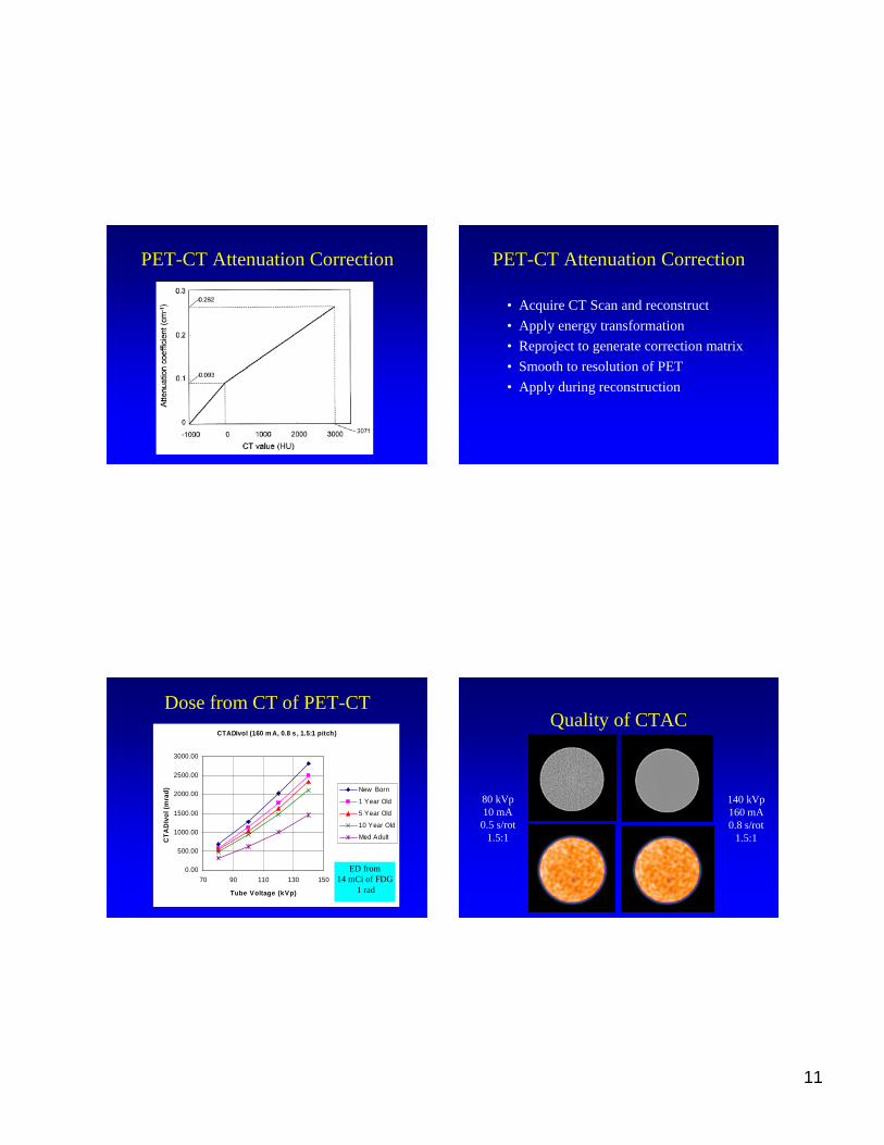
PET AttenuationCorrection
L
X
P1 = e-µx
P2 = e-µ(L-x)
PTOT = P1 x P2= e-µL
PET-CT AttenuationCorrection
11
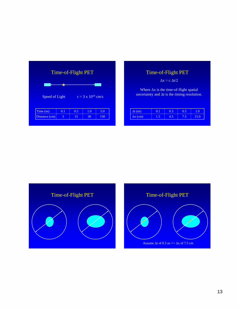
PET-CT Attenuation Correction PET-CT AttenuationCorrection
• Acquire CT Scanandreconstruct
• Apply energy transformation
• Reproject to generatecorrection matrix
• Smoothto resolution of PET
• Apply duringreconstruction
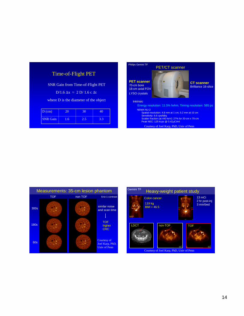
Dosefrom CT of PET-CTCTADIv ol (160 m A, 0.8 s , 1.5:1 pitc h)
0.00
500.00
1000.00
1500.00
2000.00
2500.00
3000.00
70 90 110 130 150
Tube Voltag e (kVp)
CT
AD
Ivo
l(m
rad
) New Born
1 Year Old
5 Year Old
10 Year Old
Med Adult
ED from14 mCi of FDG
1 rad
Quality of CTAC
80 kVp10 mA0.5s/rot
1.5:1
140 kVp160mA0.8 s/rot
1.5:1

12
Quality of CTAC
80 kVp10 mA0.5s/rot
1.5:1
140kVp160 mA0.8 s/rot
1.5:1
Effect of PatientSize80 kVp, 10 mA, 0.5s/rotation
Acc ura cy of Atten ua tion Correction w it h Pati ent Siz e
0.0780
0.0800
0.0820
0.0840
0.0860
0.0880
0.0900
0.0920
80/10/.5
Lin
ear
Att
enu
atio
nC
oef
fici
ent
(cm
-1)
New born
1 YO
5 YO
10 YO
15 YO
Small Adult
Med Adult
Large Adult
PET-CT Scanners
• SiemensBiograph
• GE DiscoveryST
• GE DiscoverySTE
• PhilipsGemini
PET-CT ScannersGE Discovery STE GE Dis co very ST Philips Gemin i
Detector Dimension (m m) 4.7 x 6.3 x 30 6.2 x 6.2 x 30 4 x 6 x 20# of PET Detec tors 13,440 10,080 17,864PET Detecto r Material BGO BGO GSOSpatial Resolution 5.0 6.1 4.92D/3D 2D/3D 2D/3D 3DAtten Corr CT CT CT&Cs-137
Siemens Biograph LSO Siemens Hi-Rez LSODetec tor Dimension (m m) 6.5 x 6.5 x 25 4 x 4 x 20# of PET Detectors 9,216 23,336PET Detector Materia l LSO LSOSpatia l Resoluti on 6.3 4.62D/3D 3D 3DAtten Corr CT CT
13
Time-of-Flight PET
Speed of Light c = 3 x 1010 cm/s
15030153Distance(cm)
5.01.00.50.1Time (ns)
Time-of-Flight PET
∆x = c ∆t/2
Where∆x is thetime-of-fli ght spatialuncertaintyand∆t is thetiming resolution.
15.07.54.51.5∆x (cm)
1.00.50.30.1∆t (ns)
Time-of-Flight PET Time-of-Flight PET
Assume∆t of 0.5ns=> ∆x of 7.5cm
14
Time-of-Flight PET
SNR Gainfrom Time-of-Flight PET
D/1.6∆x ≈ 2 D/ 1.6c ∆t
whereD is thediameter of theobject
3.32.51.6SNRGain
403020D (cm)
PET/CT scanner
PET scanner70-cm bore18-cm axial FOV
LYSO crystals
CT scannerBrilliance 16-slice
Philips Gemini TF
NEMA NU-2Spatial resolution: 4.8 mm at 1 cm, 5.2 mm at 10 cmSensitivity: 6.6 cps/kBqScatter fraction (at 440 keV): 27% for 20-cm x 70-cmPeak NEC: 125 kcps @ 0.42µCi/ml
Energy resolution: 11.5% fwhm, Timing resolution: 585 psIntrinsic
Courtesyof Joel Karp, PhD, Univ of Penn
Measurements: 35-cm lesion phantom
60s
TOF non TOF
180s
6-to-1 contrast
300ssimilar noiseand scan time
TOFhigherCRC
CourtesyofJoel Karp, PhD,Univ of Penn
Heavy-weight patient study13 mCi2 hr post-inj3 min/bed
MIP
Colon cancer
119 kgBMI = 46.5
non-TOF
Gemini TF
TOFLDCT
Courtesyof Joel Karp, PhD, Univ of Penn
15
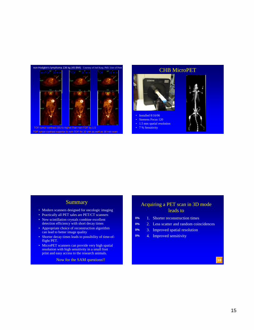
non-Hodgkin’s lymphoma 136 kg (45 BMI)
TOF tumor contrast (SUV) higher than non-TOF by 1.5
nonTOF 30 min TOF 30 min TOF 10 min
TOF tumor contrast superior to non-TOF for 10 min as well as 30 min scan
Courtesyof JoelKarp, PhD,Univ of Penn
CHB MicroPET
• Installed 8/16/06• SiemensFocus 120• 1.5 mm spatialresolution• 7 % Sensitivity
Summary• Modern scannersdesignedfor oncologic imaging• Practically all PET sales arePET/CT scanners• New scintillation crystals combine excellent
detection efficiencywith shortdecaytimes• Appropriatechoiceof reconstruction algorithm
canleadto betterimagequality• Shorter decaytimes leadsto possibility of time-of-
flight PET.• MicroPETscannerscanprovidevery high spatial
resolutionwith high sensitivi ty in a small footprint and easyaccess to theresearch animals.
Now for theSAM questions!!
Acquiring a PETscanin 3D modeleadsto
0%
0%
0%
0%
10
1. Shorterreconstructiontimes
2. Lessscatter andrandomcoincidences
3. Improved spatial resolution
4. Improved sensitivity

16
Answer
4. Improvedsensitiv ity
Reference: CherrySR,SorensonJA, PhelpsME,“Physicsin NuclearMedicine,Saunders,
PhiladelphiaPA. page351-352.
Explanation: 3D PEThasapproximatelythe samespatialresolutionas2D PETwith increasedscatterandrandom coincidences. It isalsomorecomplicatedto reconstruct.However, theremovalof theinter-planesepta leadsto a largeincreasein thelines-of-response(LORs) andthusa 4 to 5 fold increasein sensitivity.
Time-of-flight PETimprovesimagequality, particularly in
0%
0%
0%
0%
10
1. Fast scans
2. Largerpatients
3. Smallanimals
4. Time sequencesof scans
Answer
2. Larger Patients
Reference: SulemanSurti, Austin Kuhn,MatthewE. Werner,Amy E. Perkins,Jeffrey KolthammerandJoel S.Karp,“Performanceof PhilipsGeminiTF PET/CT Scannerwith SpecialConsiderationfor Its Time-of-Flight ImagingCapabilities” ,J Nucl Med 48: 471-480,2007.
Explanation: Time-of-flight PETinvolvesbothdataacquisitionandreconstruction. It allowsoneto locatetheannihilationeventalongthe line-of-responsewhich leadsto reducednoiseandhighercontrastin the imagedata. With currenttechnology,theevent canbelocalizedto within about7-8 cm which leadsto betterimageimprovement in largerpatientsbut not for small patientsor smallanimals. It is not atall relatedto thedurationof thescan or whetherthe study is acquired as a time sequence.


![Crecimiento óptimo: El Modelo de Cass-Koopmans … · sin consumo y en el segundo sin capital) θ t [] t t c r c σ = −θ ... tt tt t t t t t t. c Hc v w r e w r nv c.](https://static.fdocument.org/doc/165x107/5ba66e0109d3f263508bae94/crecimiento-optimo-el-modelo-de-cass-koopmans-sin-consumo-y-en-el-segundo.jpg)