PneumaxCatalogo 2012 Capitolo3 GB.book Page 34 Thursday ...
22
Series 1700 Size 3 3.34 Specifications may be subject to change without prior notice 3
Transcript of PneumaxCatalogo 2012 Capitolo3 GB.book Page 34 Thursday ...
Series 1700Size 3
3.34 Specifications may be subject to change without prior notice
3
PneumaxCatalogo 2012 Capitolo3_GB.book Page 34 Thursday, June 27, 2013 1:26 PM

Air Service Units Series 1700Size 3
3.35
3
Specifications may be subject to change without prior notice
Air Service UnitsSerie 1700Size 3_GB_2012Air Service UnitsFilter
Filter
Ordering code
17301c.s.t
cCONNECTIONSA = G 3/8"B = G 1/2"
sFILTER PORE SIZEA = 5μB = 20μC = 50μ
t TYPES = Automatic drain
Example: 17301A.BFilter size 3 with G 3/8" connections and filter pore size 20μ.
Flow
rat
e cu
rves
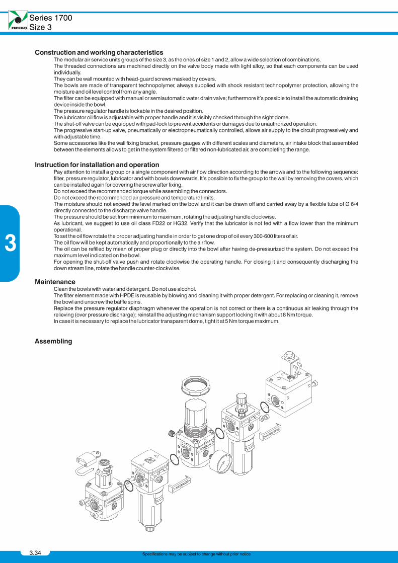
Operational characteristic Technical characteristic- Body made with light alloy.- Wall mounting possibility with M6 screws protected by covers.- Double filtering action: by air centrifuging and by replaceable and reusable HDPE porous filter
element.- Transparent technopolymer bowl with shock resistant technopolymer protection connected to
the body with bayonet cap and safety button.- Manual and semi-automatic water drain valve; in the semi-automatic version the drainage hap-
pens when there is no pressure or by pushing the valve up-wards.- Possibility to see the water level on 360°.- Automatic water drainage bowl available on request.
Connections G 3/8" - G 1/2"Max working pressure (bar) 13 bar - 1,3 MPaMinimum working pressure with automatic drain (bar) 0,5Maximum working pressure with automatic drain (bar) 10Temperature °C 50°CWeight gr. 405Filter pore size 5μ - 20μ - 50μBowl capacity 48 cm³Assembly position VerticalWall fixing screw M6Max. fittings torque 40 Nm
PneumaxCatalogo 2012 Capitolo3_GB.book Page 35 Thursday, June 27, 2013 1:26 PM
Series 1700Size 3
Air Service Units
3.36
3
Specifications may be subject to change without prior notice
Air Service UnitsCoalescing filter
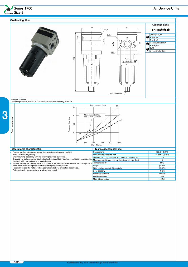
Coalescing filter
Ordering code
17308c.e.t
cCONNECTIONSA = G 3/8"B = G 1/2"
e FILTER EFFICIENCYE = 99,97%
t TYPES = Automatic drain
Example: 17308A.ECoalescing filter size 3 with G 3/8" connections and filter efficiency of 99,97%.
Flow
rat
e cu
rves
Operational characteristic Technical characteristic- Coalescing filter element remove 0,01μ particles equivalent to 99,97%.- Body made with light alloy.- Wall mounting possibility with M6 screws protected by covers.- Transparent technopolymer bowl with shock resistant technopolymer protection connected to
the body with bayonet cap and safety button.- Manual and semi-automatic water drain valve; in the semi-automatic version the drainage hap-
pens when there is no pressure or by pushing the valve up-wards.- Possibility to see the water level on 360° also with bowl protection assembled.- Automatic water drainage bowl available on request.
Connections G 3/8" - G 1/2"Max working pressure (bar) 13 bar - 1,3 MPaMinimum working pressure with automatic drain (bar) 0,5Maximum working pressure with automatic drain (bar) 10Temperature °C 50°CWeight gr. 405Filter efficiency with 0,01μ particle 99,97%Bowl capacity 48 cm³Assembly position VerticalWall fixing screw M6Max. fittings torque 40 Nm
PneumaxCatalogo 2012 Capitolo3_GB.book Page 36 Thursday, June 27, 2013 1:26 PM
Air Service Units Series 1700Size 3
3.37
3
Specifications may be subject to change without prior notice
Air Service UnitsPressure regulator
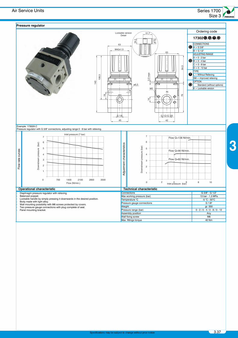
Pressure regulator
Ordering code
17302c.g.t.o
cCONNECTIONSA = G 3/8"B = G 1/2"
g
ADJUSTING RANGEA = 0 - 2 barB = 0 - 4 barC = 0 - 8 barD = 0 - 12 bar
tTYPEL = Without RelievingSM = improved relieving
oOPTION Standard (without options)K = Lockable version
Example: 17302A.CPressure regulator with G 3/8" connections, adjusting range 0 - 8 bar with relieving.
Flow
rat
e cu
rves
Adj
ustm
ent c
hara
cter
istic
s
Operational characteristic Technical characteristic- Diaphragm pressure regulator with relieving.- Balanced poppet.- Lockable handle by simply pressing it downwards in the desired position.- Body made with light alloy.- Wall mounting possibility with M6 screws protected by covers.- Two pressure gauge connections with plug complete of seal.- Panel mounting bracket.
Connections G 3/8" - G 1/2"Max working pressure (bar) 13 bar - 1,3 MPaTemperature °C -5 °C - 50°CPressure gauge connections G 1/8"Weight gr. 550Pressure range (bar) 0 - 2 / 0 - 4 / 0 - 8 / 0 - 12Assembly position AnyWall fixing screw M6Max. fittings torque 40 Nm
PneumaxCatalogo 2012 Capitolo3_GB.book Page 37 Thursday, June 27, 2013 1:26 PM
Series 1700Size 3
Air Service Units
3.38
3
Specifications may be subject to change without prior notice
Air Service UnitsPiloted pressure regulator
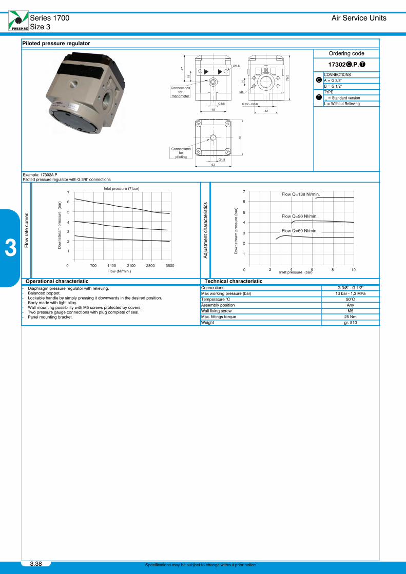
Piloted pressure regulator
Ordering code
17302c.P.t
cCONNECTIONSA = G 3/8"B = G 1/2"
tTYPE _ = Standard versionL = Without Relieving
Example: 17302A.PPiloted pressure regulator with G 3/8" connections
Flow
rat
e cu
rves
Adj
ustm
ent c
hara
cter
istic
s
Operational characteristic Technical characteristic- Diaphragm pressure regulator with relieving.- Balanced poppet.- Lockable handle by simply pressing it downwards in the desired position.- Body made with light alloy.- Wall mounting possibility with M5 screws protected by covers.- Two pressure gauge connections with plug complete of seal.- Panel mounting bracket.
Connections G 3/8" - G 1/2"Max working pressure (bar) 13 bar - 1,3 MPaTemperature °C 50°CAssembly position AnyWall fixing screw M5Max. fittings torque 25 NmWeight gr. 510
PneumaxCatalogo 2012 Capitolo3_GB.book Page 38 Thursday, June 27, 2013 1:26 PM
Air Service Units Series 1700Size 3
3.39
3
Specifications may be subject to change without prior notice
Air Service UnitsPressure regulator including manometer
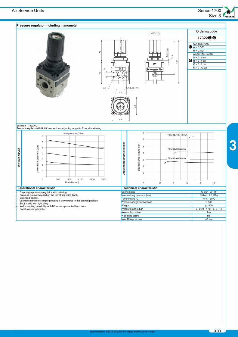
Pressure regulator including manometer
Ordering code
17322c.g
cCONNECTIONSA = G 3/8"B = G 1/2"
g
ADJUSTING RANGEA = 0 - 2 barB = 0 - 4 barC = 0 - 8 barD = 0 - 12 bar
Example: 17322A.CPressure regulator with G 3/8" connections, adjusting range 0 - 8 bar with relieving.
Flow
rat
e cu
rves
Adj
ustm
ent c
hara
cter
istic
s
Operational characteristic Technical characteristic- Diaphragm pressure regulator with relieving.- Pressure gauge included on the top of adjusting knob.- Balanced poppet.- Lockable handle by simply pressing it downwards in the desired position.- Body made with light alloy.- Wall mounting possibility with M5 screws protected by covers.- Panel mounting bracket.
Connections G 3/8" - G 1/2"Max working pressure (bar) 13 bar - 1,3 MPaTemperature °C -5 °C - 50°CPressure gauge connections G 1/8"Weight gr. 600Pressure range (bar) 0 - 2 / 0 - 4 / 0 - 8 / 0 - 12Assembly position AnyWall fixing screw M6Max. fittings torque 40 Nm
PneumaxCatalogo 2012 Capitolo3_GB.book Page 39 Thursday, June 27, 2013 1:26 PM
Series 1700Size 3
Air Service Units
3.40
3
Specifications may be subject to change without prior notice
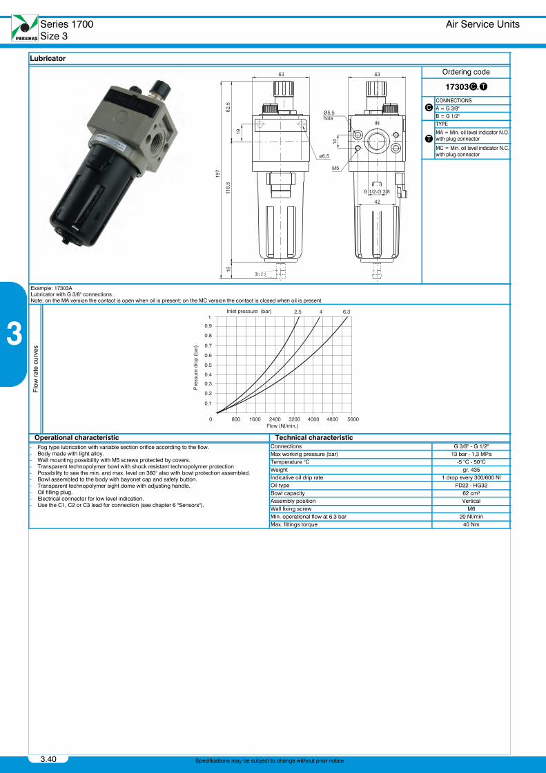
Air Service UnitsLubricator
Lubricator
Ordering code
17303c.t
cCONNECTIONSA = G 3/8"B = G 1/2"
t
TYPE
MA = Min. oil level indicator N.O.with plug connector
MC = Min. oil level indicator N.C.with plug connector
Example: 17303ALubricator with G 3/8" connections.Note: on the MA version the contact is open when oil is present; on the MC version the contact is closed when oil is present
Flow
rat
e cu
rves
Operational characteristic Technical characteristic- Fog type lubrication with variable section orifice according to the flow.- Body made with light alloy.- Wall mounting possibility with M5 screws protected by covers.- Transparent technopolymer bowl with shock resistant technopolymer protection- Possibility to see the min. and max. level on 360° also with bowl protection assembled.- Bowl assembled to the body with bayonet cap and safety button.- Transparent technopolymer sight dome with adjusting handle.- Oil filling plug.- Electrical connector for low level indication.- Use the C1, C2 or C3 lead for connection (see chapter 6 "Sensors").
Connections G 3/8" - G 1/2"Max working pressure (bar) 13 bar - 1,3 MPaTemperature °C -5 °C - 50°CWeight gr. 435Indicative oil drip rate 1 drop every 300/600 NlOil type FD22 - HG32Bowl capacity 62 cm³Assembly position VerticalWall fixing screw M6Min. operational flow at 6,3 bar 20 Nl/minMax. fittings torque 40 Nm
PneumaxCatalogo 2012 Capitolo3_GB.book Page 40 Thursday, June 27, 2013 1:26 PM
Air Service Units Series 1700Size 3
3.41
3
Specifications may be subject to change without prior notice
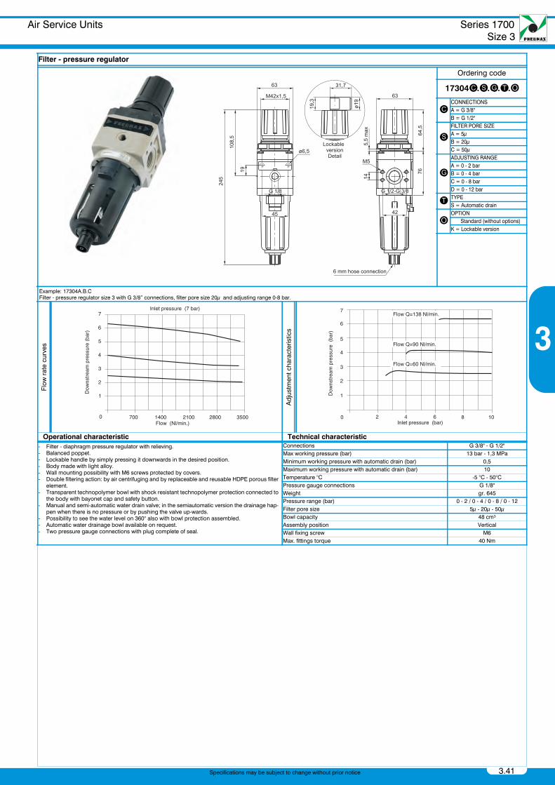
Air Service UnitsFilter - pressure regulator
Filter - pressure regulator
Ordering code
17304c.s.g.t.o
cCONNECTIONSA = G 3/8"B = G 1/2"
sFILTER PORE SIZEA = 5μB = 20μC = 50μ
g
ADJUSTING RANGEA = 0 - 2 barB = 0 - 4 barC = 0 - 8 barD = 0 - 12 bar
t TYPES = Automatic drain
oOPTION Standard (without options)K = Lockable version
Example: 17304A.B.CFilter - pressure regulator size 3 with G 3/8” connections, filter pore size 20μ and adjusting range 0-8 bar.
Flow
rat
e cu
rves
Adj
ustm
ent c
hara
cter
istic
s
Operational characteristic Technical characteristic- Filter - diaphragm pressure regulator with relieving.- Balanced poppet.- Lockable handle by simply pressing it downwards in the desired position.- Body made with light alloy.- Wall mounting possibility with M6 screws protected by covers.- Double filtering action: by air centrifuging and by replaceable and reusable HDPE porous filter
element.- Transparent technopolymer bowl with shock resistant technopolymer protection connected to
the body with bayonet cap and safety button.- Manual and semi-automatic water drain valve; in the semiautomatic version the drainage hap-
pen when there is no pressure or by pushing the valve up-wards.- Possibility to see the water level on 360° also with bowl protection assembled.- Automatic water drainage bowl available on request.- Two pressure gauge connections with plug complete of seal.
Connections G 3/8" - G 1/2"Max working pressure (bar) 13 bar - 1,3 MPaMinimum working pressure with automatic drain (bar) 0,5Maximum working pressure with automatic drain (bar) 10Temperature °C -5 °C - 50°CPressure gauge connections G 1/8"Weight gr. 645Pressure range (bar) 0 - 2 / 0 - 4 / 0 - 8 / 0 - 12Filter pore size 5μ - 20μ - 50μBowl capacity 48 cm³Assembly position VerticalWall fixing screw M6Max. fittings torque 40 Nm
PneumaxCatalogo 2012 Capitolo3_GB.book Page 41 Thursday, June 27, 2013 1:26 PM
Series 1700Size 3
Air Service Units
3.42
3
Specifications may be subject to change without prior notice
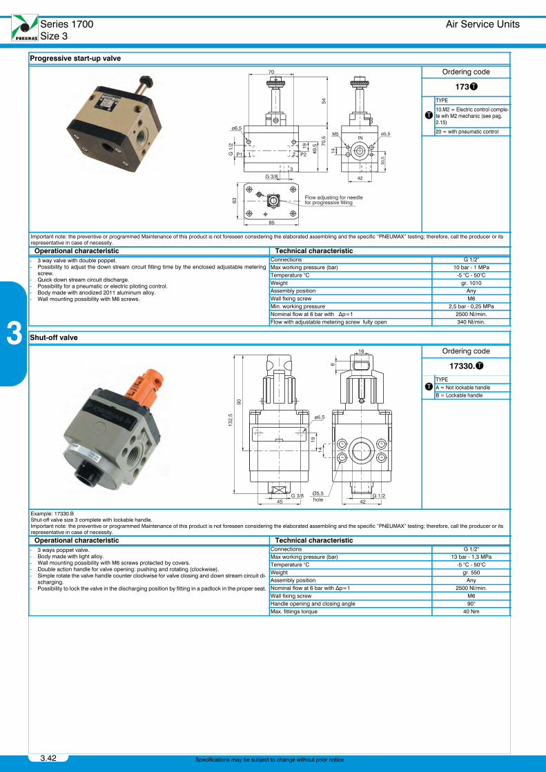
Air Service UnitsProgressive start-up valve
Air Service UnitsShut-off valve
Progressive start-up valve
Ordering code
173t
t
TYPE
10.M2 = Electric control comple-te wih M2 mechanic (see pag. 2.15)
20 = with pneumatic control
Important note: the preventive or programmed Maintenance of this product is not foreseen considering the elaborated assembling and the specific “PNEUMAX” testing; therefore, call the producer or its representative in case of necessity.
Operational characteristic Technical characteristic- 3 way valve with double poppet.- Possibility to adjust the down stream circuit filling time by the enclosed adjustable metering
screw.- Quick down stream circuit discharge.- Possibility for a pneumatic or electric piloting control.- Body made with anodized 2011 aluminum alloy.- Wall mounting possibility with M6 screws.
Connections G 1/2"Max working pressure (bar) 10 bar - 1 MPaTemperature °C -5 °C - 50°CWeight gr. 1010Assembly position AnyWall fixing screw M6Min. working pressure 2,5 bar - 0,25 MPaNominal flow at 6 bar with ∆p=1 2500 Nl/min.Flow with adjustable metering screw fully open 340 Nl/min.
Shut-off valve
Ordering code
17330.t
tTYPEA = Not lockable handleB = Lockable handle
Example: 17330.BShut-off valve size 3 complete with lockable handle.Important note: the preventive or programmed Maintenance of this product is not foreseen considering the elaborated assembling and the specific “PNEUMAX” testing; therefore, call the producer or its representative in case of necessity.
Operational characteristic Technical characteristic- 3 ways poppet valve.- Body made with light alloy.- Wall mounting possibility with M6 screws protected by covers.- Double action handle for valve opening: pushing and rotating (clockwise).- Simple rotate the valve handle counter clockwise for valve closing and down stream circuit di-
scharging.- Possibility to lock the valve in the discharging position by fitting in a padlock in the proper seat.
Connections G 1/2"Max working pressure (bar) 13 bar - 1,3 MPaTemperature °C -5 °C - 50°CWeight gr. 550Assembly position AnyNominal flow at 6 bar with ∆p=1 2500 Nl/min.Wall fixing screw M6Handle opening and closing angle 90°Max. fittings torque 40 Nm
PneumaxCatalogo 2012 Capitolo3_GB.book Page 42 Thursday, June 27, 2013 1:26 PM
Air Service Units Series 1700Size 3
3.43
3
Specifications may be subject to change without prior notice
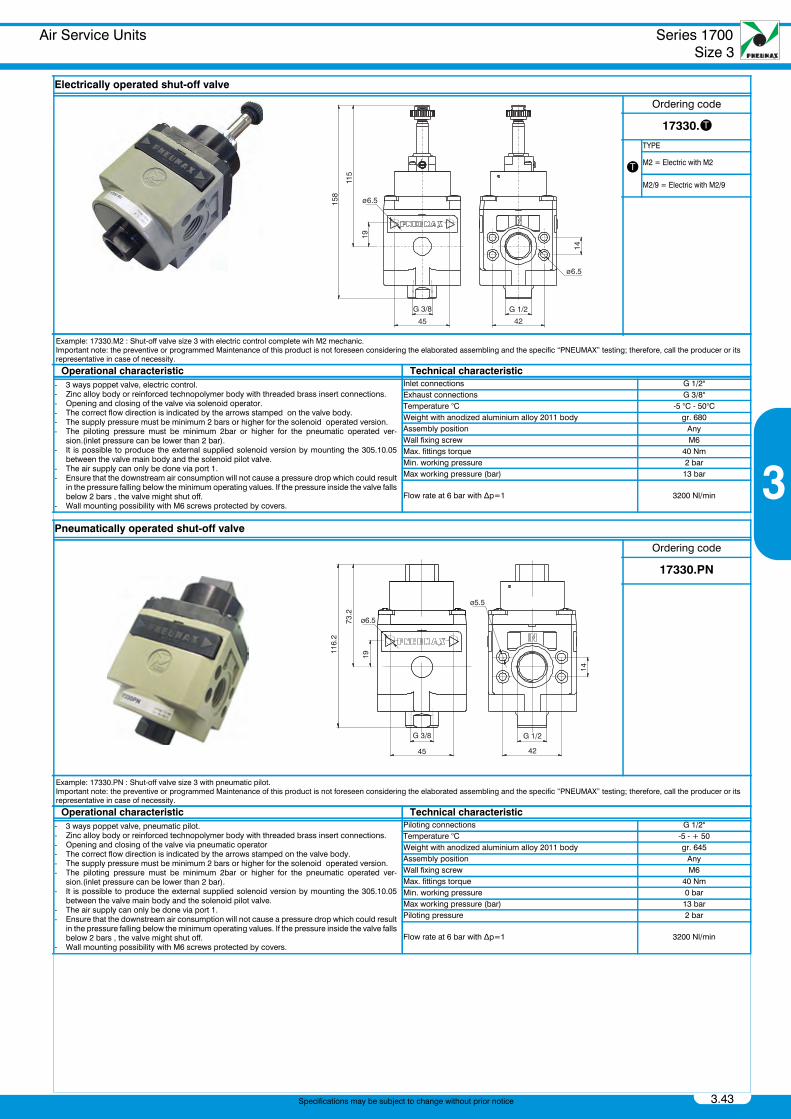
Air Service UnitsElectrically operated shut-off valve
Air Service UnitsPneumatically operated shut-off valve
Electrically operated shut-off valve
Ordering code
17330.t
t
TYPE
M2 = Electric with M2
M2/9 = Electric with M2/9
Example: 17330.M2 : Shut-off valve size 3 with electric control complete wih M2 mechanic.Important note: the preventive or programmed Maintenance of this product is not foreseen considering the elaborated assembling and the specific “PNEUMAX” testing; therefore, call the producer or its representative in case of necessity.
Operational characteristic Technical characteristic- 3 ways poppet valve, electric control.- Zinc alloy body or reinforced technopolymer body with threaded brass insert connections.- Opening and closing of the valve via solenoid operator.- The correct flow direction is indicated by the arrows stamped on the valve body.- The supply pressure must be minimum 2 bars or higher for the solenoid operated version.- The piloting pressure must be minimum 2bar or higher for the pneumatic operated ver-
sion.(inlet pressure can be lower than 2 bar).- It is possible to produce the external supplied solenoid version by mounting the 305.10.05
between the valve main body and the solenoid pilot valve.- The air supply can only be done via port 1.- Ensure that the downstream air consumption will not cause a pressure drop which could result
in the pressure falling below the minimum operating values. If the pressure inside the valve fallsbelow 2 bars , the valve might shut off.
- Wall mounting possibility with M6 screws protected by covers.
Inlet connections G 1/2"Exhaust connections G 3/8"Temperature °C -5 °C - 50°CWeight with anodized aluminium alloy 2011 body gr. 680Assembly position AnyWall fixing screw M6Max. fittings torque 40 NmMin. working pressure 2 barMax working pressure (bar) 13 bar
Flow rate at 6 bar with ∆p=1 3200 Nl/min
Pneumatically operated shut-off valve
Ordering code
17330.PN
Example: 17330.PN : Shut-off valve size 3 with pneumatic pilot.Important note: the preventive or programmed Maintenance of this product is not foreseen considering the elaborated assembling and the specific “PNEUMAX” testing; therefore, call the producer or its representative in case of necessity.
Operational characteristic Technical characteristic- 3 ways poppet valve, pneumatic pilot.- Zinc alloy body or reinforced technopolymer body with threaded brass insert connections.- Opening and closing of the valve via pneumatic operator- The correct flow direction is indicated by the arrows stamped on the valve body.- The supply pressure must be minimum 2 bars or higher for the solenoid operated version.- The piloting pressure must be minimum 2bar or higher for the pneumatic operated ver-
sion.(inlet pressure can be lower than 2 bar).- It is possible to produce the external supplied solenoid version by mounting the 305.10.05
between the valve main body and the solenoid pilot valve.- The air supply can only be done via port 1.- Ensure that the downstream air consumption will not cause a pressure drop which could result
in the pressure falling below the minimum operating values. If the pressure inside the valve fallsbelow 2 bars , the valve might shut off.
- Wall mounting possibility with M6 screws protected by covers.
Piloting connections G 1/2"Temperature °C -5 - + 50Weight with anodized aluminium alloy 2011 body gr. 645Assembly position AnyWall fixing screw M6Max. fittings torque 40 NmMin. working pressure 0 barMax working pressure (bar) 13 barPiloting pressure 2 bar
Flow rate at 6 bar with ∆p=1 3200 Nl/min
ø6.5
G 3/8
45
19
115
158
14
G 1/2
42
ø6.5
PneumaxCatalogo 2012 Capitolo3_GB.book Page 43 Thursday, June 27, 2013 1:26 PM
Series 1700Size 3
Air Service Units
3.44
3
Specifications may be subject to change without prior notice
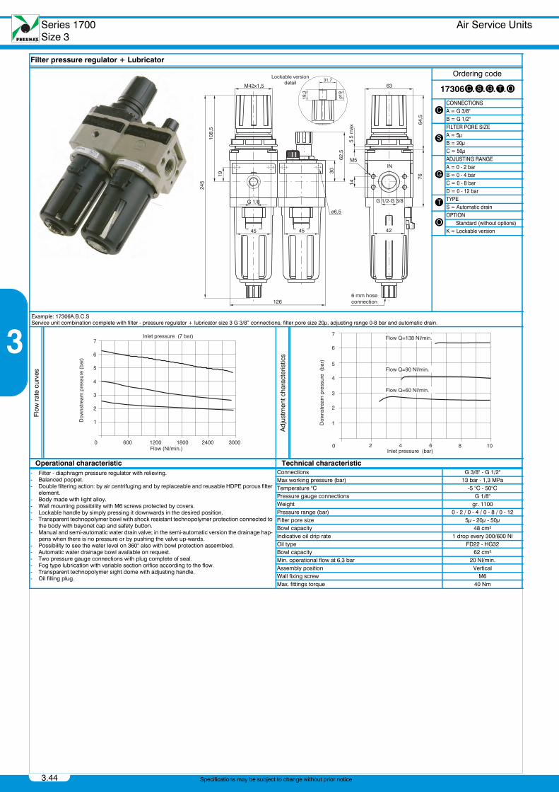
Air Service UnitsFilter pressure regulator + Lubricator
Filter pressure regulator + Lubricator
Ordering code
17306c.s.g.t.o
cCONNECTIONSA = G 3/8"B = G 1/2"
sFILTER PORE SIZEA = 5μB = 20μC = 50μ
g
ADJUSTING RANGEA = 0 - 2 barB = 0 - 4 barC = 0 - 8 barD = 0 - 12 bar
t TYPES = Automatic drain
oOPTION Standard (without options)K = Lockable version
Example: 17306A.B.C.SService unit combination complete with filter - pressure regulator + lubricator size 3 G 3/8” connections, filter pore size 20μ, adjusting range 0-8 bar and automatic drain.
Flow
rat
e cu
rves
Adj
ustm
ent c
hara
cter
istic
s
Operational characteristic Technical characteristic- Filter - diaphragm pressure regulator with relieving.- Balanced poppet.- Double filtering action: by air centrifuging and by replaceable and reusable HDPE porous filter
element.- Body made with light alloy.- Wall mounting possibility with M6 screws protected by covers.- Lockable handle by simply pressing it downwards in the desired position.- Transparent technopolymer bowl with shock resistant technopolymer protection connected to
the body with bayonet cap and safety button.- Manual and semi-automatic water drain valve; in the semi-automatic version the drainage hap-
pens when there is no pressure or by pushing the valve up-wards.- Possibility to see the water level on 360° also with bowl protection assembled.- Automatic water drainage bowl available on request.- Two pressure gauge connections with plug complete of seal.- Fog type lubrication with variable section orifice according to the flow.- Transparent technopolymer sight dome with adjusting handle.- Oil filling plug.
Connections G 3/8" - G 1/2"Max working pressure (bar) 13 bar - 1,3 MPaTemperature °C -5 °C - 50°CPressure gauge connections G 1/8"Weight gr. 1100Pressure range (bar) 0 - 2 / 0 - 4 / 0 - 8 / 0 - 12Filter pore size 5μ - 20μ - 50μBowl capacity 48 cm³Indicative oil drip rate 1 drop every 300/600 NlOil type FD22 - HG32Bowl capacity 62 cm³Min. operational flow at 6,3 bar 20 Nl/min.Assembly position VerticalWall fixing screw M6Max. fittings torque 40 Nm
PneumaxCatalogo 2012 Capitolo3_GB.book Page 44 Thursday, June 27, 2013 1:26 PM
Air Service Units Series 1700Size 3
3.45
3
Specifications may be subject to change without prior notice
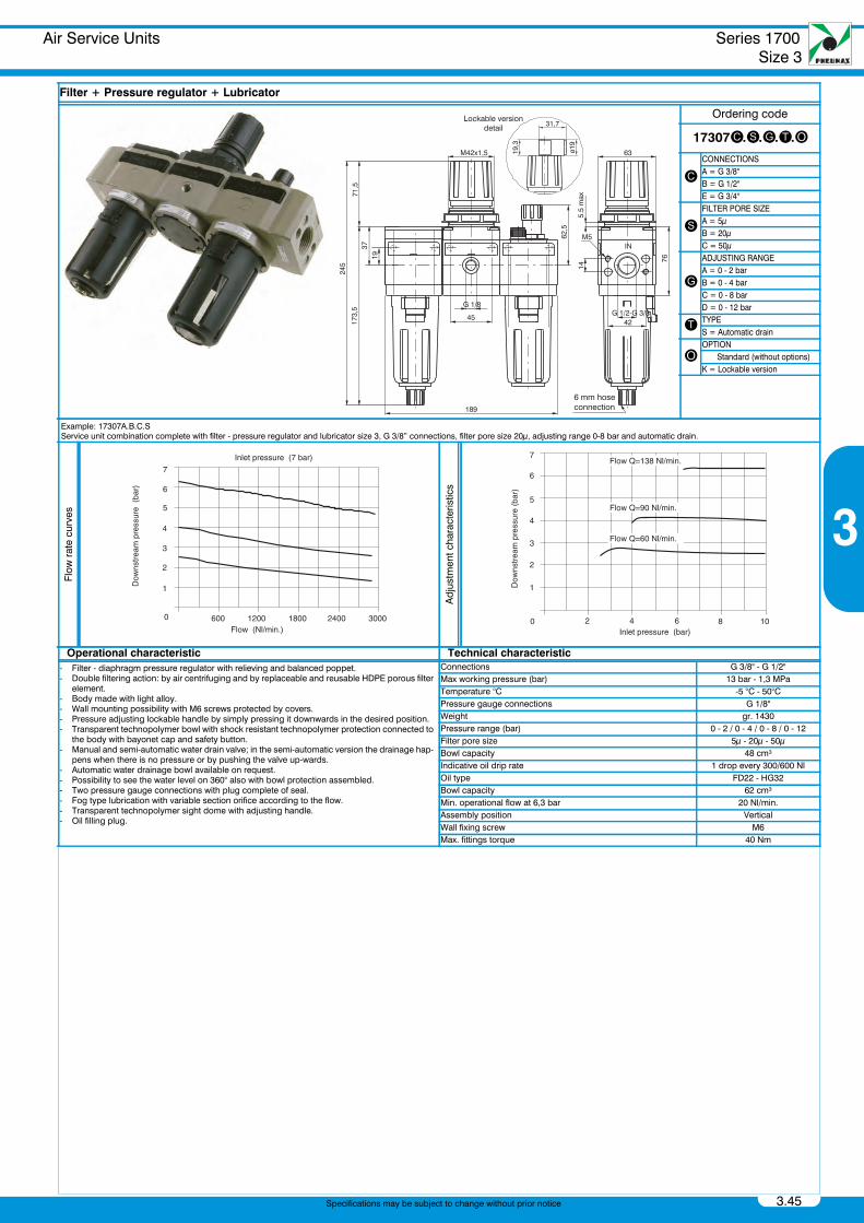
Air Service UnitsFilter + Pressure regulator + Lubricator
Filter + Pressure regulator + Lubricator
Ordering code
17307c.s.g.t.o
cCONNECTIONSA = G 3/8"B = G 1/2"E = G 3/4"
sFILTER PORE SIZEA = 5μB = 20μC = 50μ
g
ADJUSTING RANGEA = 0 - 2 barB = 0 - 4 barC = 0 - 8 barD = 0 - 12 bar
t TYPES = Automatic drain
oOPTION Standard (without options)K = Lockable version
Example: 17307A.B.C.SService unit combination complete with filter - pressure regulator and lubricator size 3, G 3/8” connections, filter pore size 20μ, adjusting range 0-8 bar and automatic drain.
Flow
rat
e cu
rves
Adj
ustm
ent c
hara
cter
istic
s
Operational characteristic Technical characteristic- Filter - diaphragm pressure regulator with relieving and balanced poppet.- Double filtering action: by air centrifuging and by replaceable and reusable HDPE porous filter
element.- Body made with light alloy.- Wall mounting possibility with M6 screws protected by covers.- Pressure adjusting lockable handle by simply pressing it downwards in the desired position.- Transparent technopolymer bowl with shock resistant technopolymer protection connected to
the body with bayonet cap and safety button.- Manual and semi-automatic water drain valve; in the semi-automatic version the drainage hap-
pens when there is no pressure or by pushing the valve up-wards.- Automatic water drainage bowl available on request.- Possibility to see the water level on 360° also with bowl protection assembled.- Two pressure gauge connections with plug complete of seal.- Fog type lubrication with variable section orifice according to the flow.- Transparent technopolymer sight dome with adjusting handle.- Oil filling plug.
Connections G 3/8" - G 1/2"Max working pressure (bar) 13 bar - 1,3 MPaTemperature °C -5 °C - 50°CPressure gauge connections G 1/8"Weight gr. 1430Pressure range (bar) 0 - 2 / 0 - 4 / 0 - 8 / 0 - 12Filter pore size 5μ - 20μ - 50μBowl capacity 48 cm³Indicative oil drip rate 1 drop every 300/600 NlOil type FD22 - HG32Bowl capacity 62 cm³Min. operational flow at 6,3 bar 20 Nl/min.Assembly position VerticalWall fixing screw M6Max. fittings torque 40 Nm
PneumaxCatalogo 2012 Capitolo3_GB.book Page 45 Thursday, June 27, 2013 1:26 PM
Series 1700Size 3
Air Service Units
3.46
3
Specifications may be subject to change without prior notice
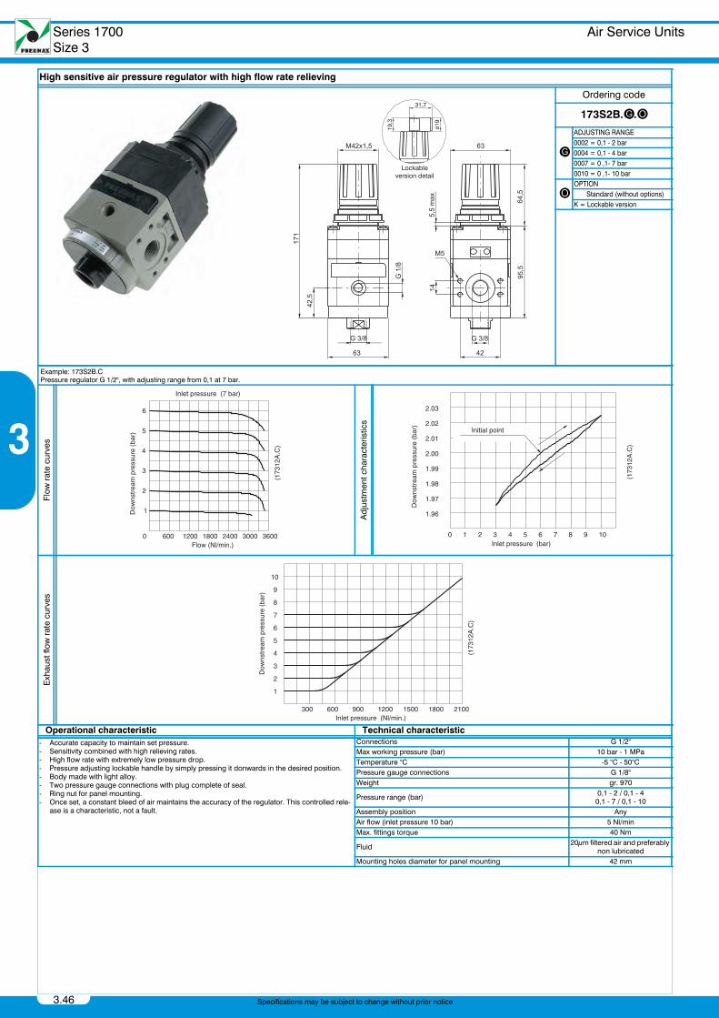
Air Service UnitsHigh sensitive air pressure regulator with high flow rate relieving
High sensitive air pressure regulator with high flow rate relieving
Ordering code
173S2B.g.o
g
ADJUSTING RANGE0002 = 0,1 - 2 bar0004 = 0,1 - 4 bar0007 = 0 ,1- 7 bar0010 = 0 ,1- 10 bar
oOPTION Standard (without options)K = Lockable version
Example: 173S2B.CPressure regulator G 1/2", with adjusting range from 0,1 at 7 bar.
Flow
rat
e cu
rves
Adj
ustm
ent c
hara
cter
istic
s
Exh
aust
flow
rat
e cu
rves
Operational characteristic Technical characteristic- Accurate capacity to maintain set pressure.- Sensitivity combined with high relieving rates.- High flow rate with extremely low pressure drop.- Pressure adjusting lockable handle by simply pressing it donwards in the desired position.- Body made with light alloy.- Two pressure gauge connections with plug complete of seal.- Ring nut for panel mounting.- Once set, a constant bleed of air maintains the accuracy of the regulator. This controlled rele-
ase is a characteristic, not a fault.
Connections G 1/2"Max working pressure (bar) 10 bar - 1 MPaTemperature °C -5 °C - 50°CPressure gauge connections G 1/8"Weight gr. 970
Pressure range (bar) 0,1 - 2 / 0,1 - 40,1 - 7 / 0,1 - 10
Assembly position AnyAir flow (inlet pressure 10 bar) 5 Nl/minMax. fittings torque 40 Nm
Fluid 20μm filtered air and preferably non lubricated
Mounting holes diameter for panel mounting 42 mm
PneumaxCatalogo 2012 Capitolo3_GB.book Page 46 Thursday, June 27, 2013 1:26 PM
Air Service Units Series 1700Size 3
3.47
3
Specifications may be subject to change without prior notice
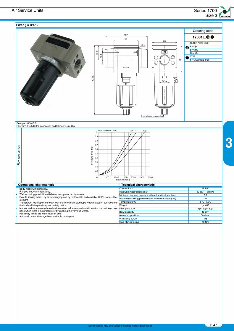
Air Service UnitsFilter ( G 3/4" )
Filter ( G 3/4" )
Ordering code
17301E.s.t
sFILTER PORE SIZEA = 5μB = 20μC = 50μ
t TYPES = Automatic drain
Example: 17301E.BFilter size 3 with G 3/4" connection and filter pore size 20μ.
Flow
rat
e cu
rves
Operational characteristic Technical characteristic- Body made with light alloy.- Flanges made with light alloy.- Wall mounting possibility with M6 screws protected by covers.- Double filtering action: by air centrifuging and by replaceable and reusable HDPE porous filter
element.- Transparent technopolymer bowl with shock resistant technopolymer protection connected to
the body with bayonet cap and safety button.- Manual and semi-automatic water drain valve; in the semi-automatic version the drainage hap-
pens when there is no pressure or by pushing the valve up-wards.- Possibility to see the water level on 360°.- Automatic water drainage bowl available on request.
Connections G 3/4"Max working pressure (bar) 13 bar - 1,3 MPaMinimum working pressure with automatic drain (bar) 0,5Maximum working pressure with automatic drain (bar) 10Temperature °C -5 °C - 50°CWeight gr. 405Filter pore size 5μ - 20μ - 50μBowl capacity 48 cm³Assembly position VerticalWall fixing screw M6Max. fittings torque 40 Nm
PneumaxCatalogo 2012 Capitolo3_GB.book Page 47 Thursday, June 27, 2013 1:26 PM
Series 1700Size 3
Air Service Units
3.48
3
Specifications may be subject to change without prior notice
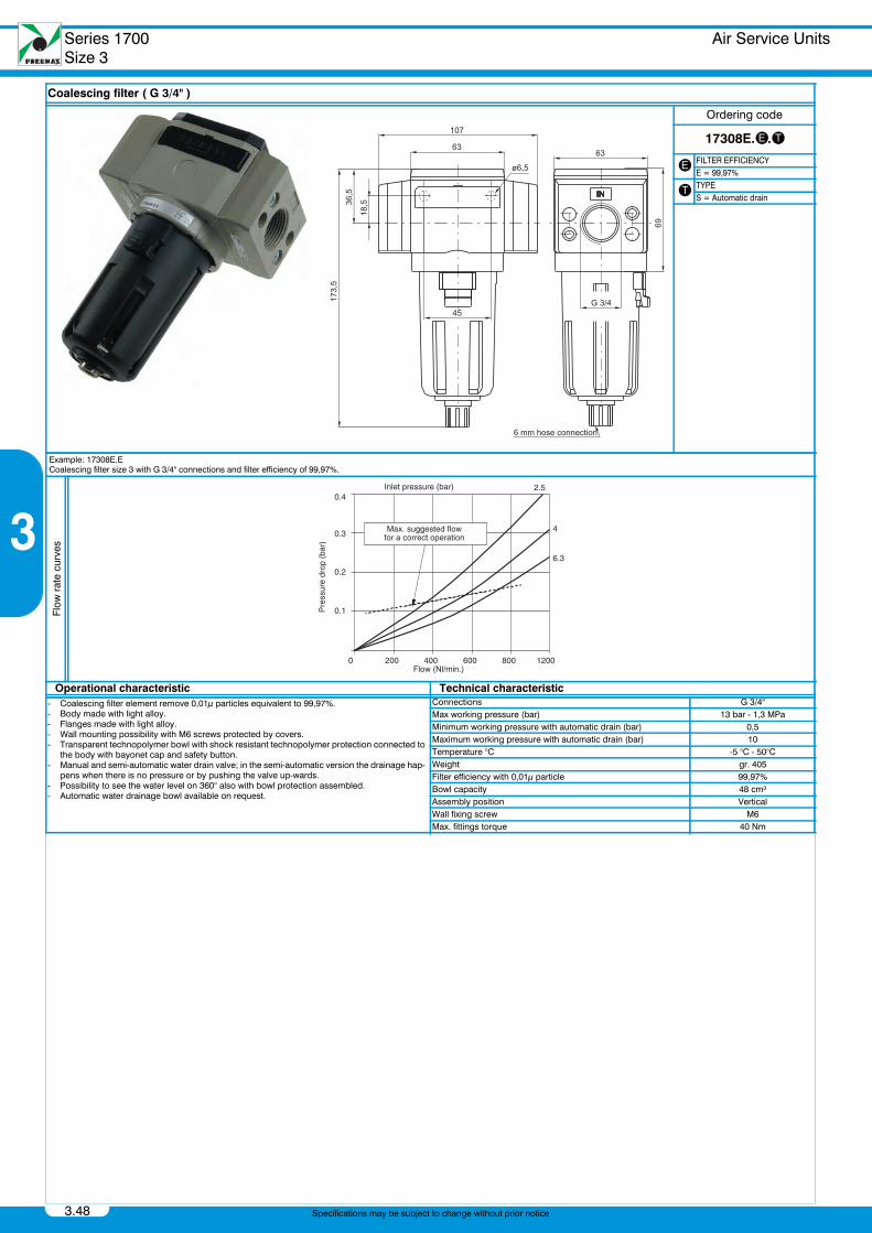
Air Service UnitsCoalescing filter ( G 3/4" )
Coalescing filter ( G 3/4" )
Ordering code
17308E.e.t
e FILTER EFFICIENCYE = 99,97%
t TYPES = Automatic drain
Example: 17308E.ECoalescing filter size 3 with G 3/4" connections and filter efficiency of 99,97%.
Flow
rat
e cu
rves
Operational characteristic Technical characteristic- Coalescing filter element remove 0,01μ particles equivalent to 99,97%.- Body made with light alloy.- Flanges made with light alloy.- Wall mounting possibility with M6 screws protected by covers.- Transparent technopolymer bowl with shock resistant technopolymer protection connected to
the body with bayonet cap and safety button.- Manual and semi-automatic water drain valve; in the semi-automatic version the drainage hap-
pens when there is no pressure or by pushing the valve up-wards.- Possibility to see the water level on 360° also with bowl protection assembled.- Automatic water drainage bowl available on request.
Connections G 3/4"Max working pressure (bar) 13 bar - 1,3 MPaMinimum working pressure with automatic drain (bar) 0,5Maximum working pressure with automatic drain (bar) 10Temperature °C -5 °C - 50°CWeight gr. 405Filter efficiency with 0,01μ particle 99,97%Bowl capacity 48 cm³Assembly position VerticalWall fixing screw M6Max. fittings torque 40 Nm
PneumaxCatalogo 2012 Capitolo3_GB.book Page 48 Thursday, June 27, 2013 1:26 PM

Air Service Units Series 1700Size 3
3.49
3
Specifications may be subject to change without prior notice
Air Service UnitsPressure regulator ( G 3/4" )
Pressure regulator ( G 3/4" )
Ordering code
17302Eg.t.o
g
ADJUSTING RANGEA = 0 - 2 barB = 0 - 4 barC = 0 - 8 barD = 0 - 12 bar
tTYPEL = without RelievingSM = improved relieving
oOPTION Standard (without options)K = Lockable version
Example: 17302E.CPressure regulator size 3 with G 3/4" connections, adjusting range 0 - 8 bar with relieving.
Flow
rat
e cu
rves
Adj
ustm
ent c
hara
cter
istic
s
Operational characteristic Technical characteristic- Diaphragm pressure regulator with relieving.- Balanced poppet.- Lockable handle by simply pressing it downwards in the desired position.- Body made with light alloy.- Flange made with light alloy- Wall mounting possibility with M6 screws protected by covers.- Two pressure gauge connections with plug complete of seal.- Panel mounting bracket.
Connections G 3/4"Max working pressure (bar) 13 bar - 1,3 MPaTemperature °C -5 °C - 50°CPressure gauge connections G 1/8"Weight gr. 550Pressure range (bar) 0 - 2 / 0 - 4 / 0 - 8 / 0 - 12Assembly position AnyWall fixing screw M6Max. fittings torque 40 Nm
PneumaxCatalogo 2012 Capitolo3_GB.book Page 49 Thursday, June 27, 2013 1:26 PM
Series 1700Size 3
Air Service Units
3.50
3
Specifications may be subject to change without prior notice
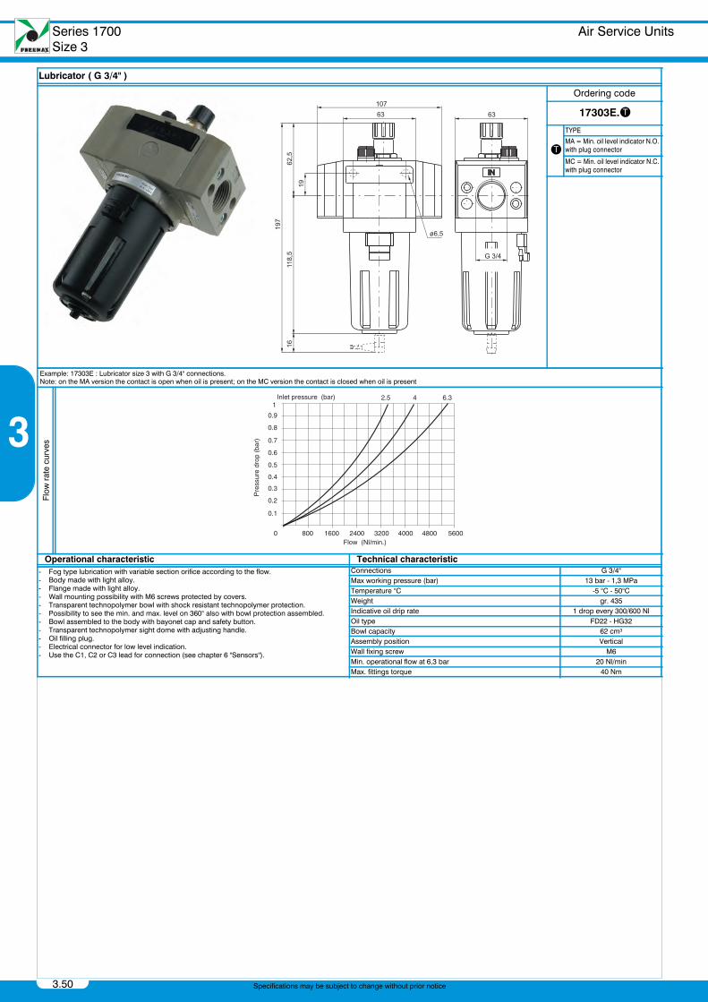
Air Service UnitsLubricator ( G 3/4" )
Lubricator ( G 3/4" )
Ordering code
17303E.t
t
TYPE
MA = Min. oil level indicator N.O. with plug connector
MC = Min. oil level indicator N.C. with plug connector
Example: 17303E : Lubricator size 3 with G 3/4" connections.Note: on the MA version the contact is open when oil is present; on the MC version the contact is closed when oil is present
Flow
rat
e cu
rves
Operational characteristic Technical characteristic- Fog type lubrication with variable section orifice according to the flow.- Body made with light alloy.- Flange made with light alloy.- Wall mounting possibility with M6 screws protected by covers.- Transparent technopolymer bowl with shock resistant technopolymer protection.- Possibility to see the min. and max. level on 360° also with bowl protection assembled.- Bowl assembled to the body with bayonet cap and safety button.- Transparent technopolymer sight dome with adjusting handle.- Oil filling plug.- Electrical connector for low level indication.- Use the C1, C2 or C3 lead for connection (see chapter 6 "Sensors").
Connections G 3/4"Max working pressure (bar) 13 bar - 1,3 MPaTemperature °C -5 °C - 50°CWeight gr. 435Indicative oil drip rate 1 drop every 300/600 NlOil type FD22 - HG32Bowl capacity 62 cm³Assembly position VerticalWall fixing screw M6Min. operational flow at 6,3 bar 20 Nl/minMax. fittings torque 40 Nm
PneumaxCatalogo 2012 Capitolo3_GB.book Page 50 Thursday, June 27, 2013 1:26 PM
Air Service Units Series 1700Size 3
3.51
3
Specifications may be subject to change without prior notice
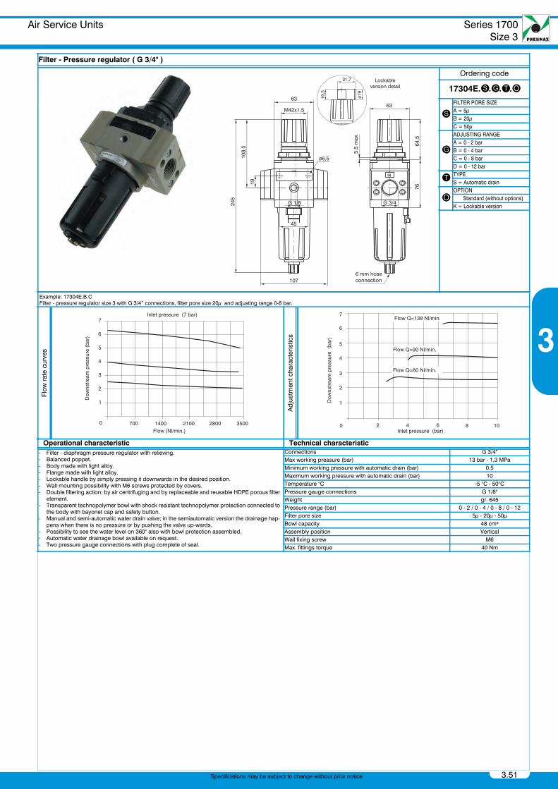
Air Service UnitsFilter - Pressure regulator ( G 3/4" )
Filter - Pressure regulator ( G 3/4" )
Ordering code
17304E.s.g.t.o
sFILTER PORE SIZEA = 5μB = 20μC = 50μ
g
ADJUSTING RANGEA = 0 - 2 barB = 0 - 4 barC = 0 - 8 barD = 0 - 12 bar
t TYPES = Automatic drain
oOPTION Standard (without options)K = Lockable version
Example: 17304E.B.CFilter - pressure regulator size 3 with G 3/4” connections, filter pore size 20μ and adjusting range 0-8 bar.
Flow
rat
e cu
rves
Adj
ustm
ent c
hara
cter
istic
s
Operational characteristic Technical characteristic- Filter - diaphragm pressure regulator with relieving.- Balanced poppet.- Body made with light alloy.- Flange made with light alloy.- Lockable handle by simply pressing it downwards in the desired position.- Wall mounting possibility with M6 screws protected by covers.- Double filtering action: by air centrifuging and by replaceable and reusable HDPE porous filter
element.- Transparent technopolymer bowl with shock resistant technopolymer protection connected to
the body with bayonet cap and safety button.- Manual and semi-automatic water drain valve; in the semiautomatic version the drainage hap-
pens when there is no pressure or by pushing the valve up-wards.- Possibility to see the water level on 360° also with bowl protection assembled.- Automatic water drainage bowl available on request.- Two pressure gauge connections with plug complete of seal.
Connections G 3/4"Max working pressure (bar) 13 bar - 1,3 MPaMinimum working pressure with automatic drain (bar) 0,5Maximum working pressure with automatic drain (bar) 10Temperature °C -5 °C - 50°CPressure gauge connections G 1/8"Weight gr. 645Pressure range (bar) 0 - 2 / 0 - 4 / 0 - 8 / 0 - 12Filter pore size 5μ - 20μ - 50μBowl capacity 48 cm³Assembly position VerticalWall fixing screw M6Max. fittings torque 40 Nm
PneumaxCatalogo 2012 Capitolo3_GB.book Page 51 Thursday, June 27, 2013 1:26 PM
Series 1700Size 3
Air Service Units
3.52
3
Specifications may be subject to change without prior notice
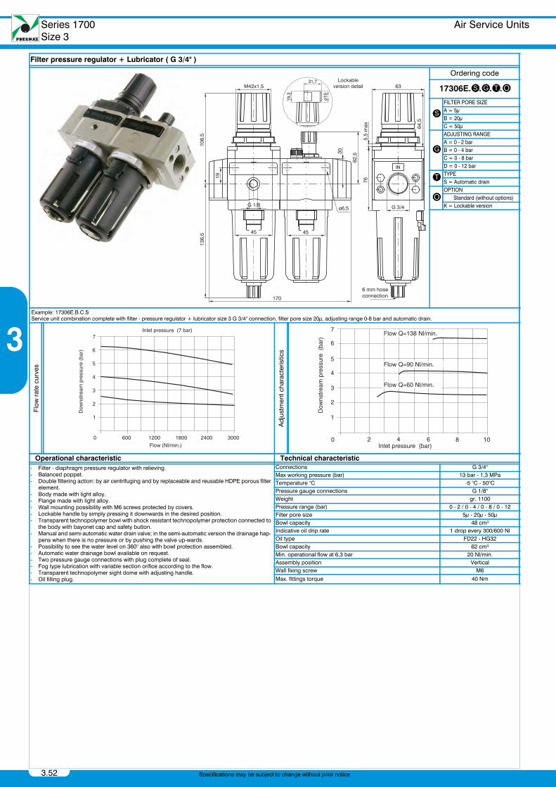
Air Service UnitsFilter pressure regulator + Lubricator ( G 3/4" )
Filter pressure regulator + Lubricator ( G 3/4" )
Ordering code
17306E.s.g.t.o
sFILTER PORE SIZEA = 5μB = 20μC = 50μ
g
ADJUSTING RANGEA = 0 - 2 barB = 0 - 4 barC = 0 - 8 barD = 0 - 12 bar
t TYPES = Automatic drain
oOPTION Standard (without options)K = Lockable version
Example: 17306E.B.C.SService unit combination complete with filter - pressure regulator + lubricator size 3 G 3/4" connection, filter pore size 20μ, adjusting range 0-8 bar and automatic drain.
Flow
rat
e cu
rves
Adj
ustm
ent c
hara
cter
istic
s
Operational characteristic Technical characteristic- Filter - diaphragm pressure regulator with relieving.- Balanced poppet.- Double filtering action: by air centrifuging and by replaceable and reusable HDPE porous filter
element.- Body made with light alloy.- Flange made with light alloy.- Wall mounting possibility with M6 screws protected by covers.- Lockable handle by simply pressing it downwards in the desired position.- Transparent technopolymer bowl with shock resistant technopolymer protection connected to
the body with bayonet cap and safety button.- Manual and semi-automatic water drain valve; in the semi-automatic version the drainage hap-
pens when there is no pressure or by pushing the valve up-wards.- Possibility to see the water level on 360° also with bowl protection assembled.- Automatic water drainage bowl available on request.- Two pressure gauge connections with plug complete of seal.- Fog type lubrication with variable section orifice according to the flow.- Transparent technopolymer sight dome with adjusting handle.- Oil filling plug.
Connections G 3/4"Max working pressure (bar) 13 bar - 1,3 MPaTemperature °C -5 °C - 50°CPressure gauge connections G 1/8"Weight gr. 1100Pressure range (bar) 0 - 2 / 0 - 4 / 0 - 8 / 0 - 12Filter pore size 5μ - 20μ - 50μBowl capacity 48 cm³Indicative oil drip rate 1 drop every 300/600 NlOil type FD22 - HG32Bowl capacity 62 cm³Min. operational flow at 6,3 bar 20 Nl/min.Assembly position VerticalWall fixing screw M6
Max. fittings torque 40 Nm
PneumaxCatalogo 2012 Capitolo3_GB.book Page 52 Thursday, June 27, 2013 1:26 PM
Air Service Units Series 1700Size 3
3.53
3
Specifications may be subject to change without prior notice
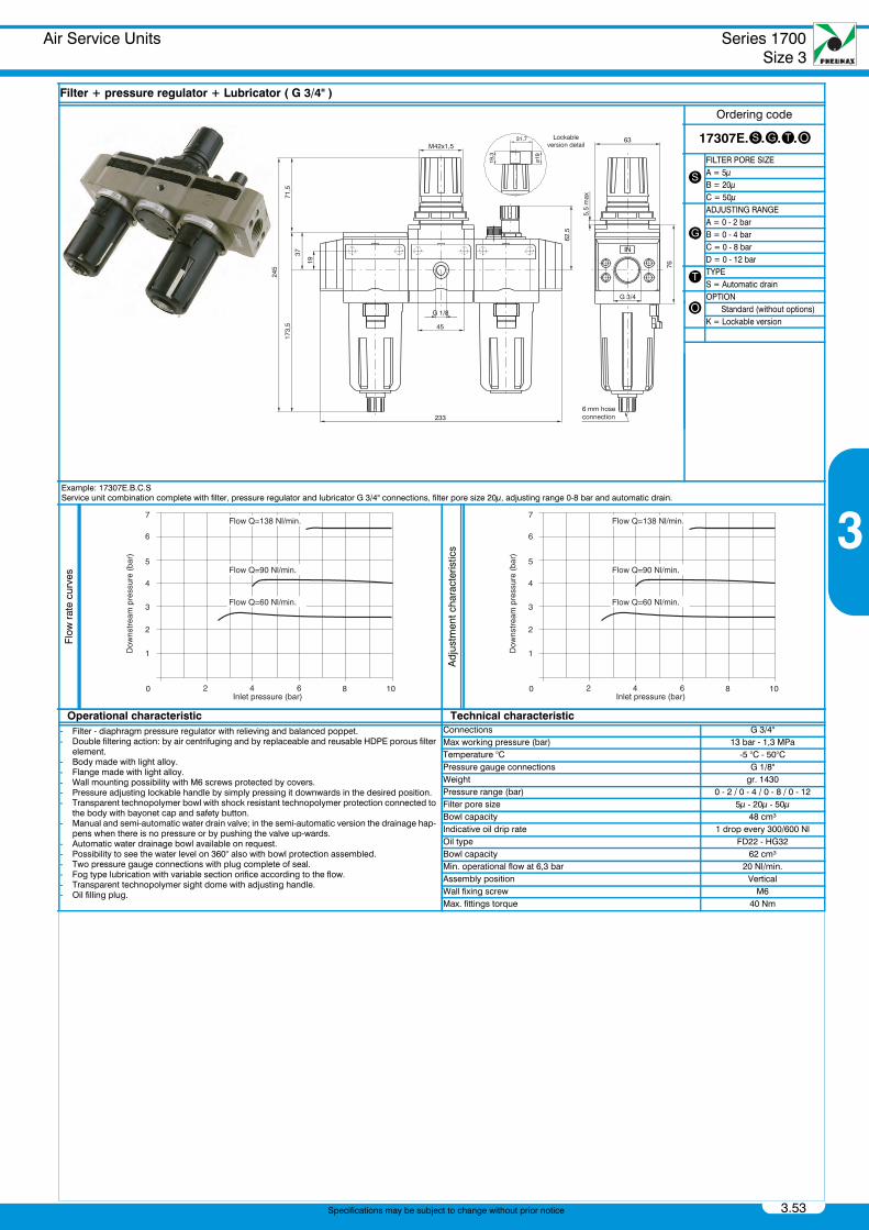
Air Service UnitsFilter + pressure regulator + Lubricator ( G 3/4" )
Filter + pressure regulator + Lubricator ( G 3/4" )
Ordering code
17307E.s.g.t.o
sFILTER PORE SIZEA = 5μB = 20μC = 50μ
g
ADJUSTING RANGEA = 0 - 2 barB = 0 - 4 barC = 0 - 8 barD = 0 - 12 bar
t TYPES = Automatic drain
oOPTION Standard (without options)K = Lockable version
Example: 17307E.B.C.SService unit combination complete with filter, pressure regulator and lubricator G 3/4" connections, filter pore size 20μ, adjusting range 0-8 bar and automatic drain.
Flow
rat
e cu
rves
Adj
ustm
ent c
hara
cter
istic
s
Operational characteristic Technical characteristic- Filter - diaphragm pressure regulator with relieving and balanced poppet.- Double filtering action: by air centrifuging and by replaceable and reusable HDPE porous filter
element.- Body made with light alloy.- Flange made with light alloy.- Wall mounting possibility with M6 screws protected by covers.- Pressure adjusting lockable handle by simply pressing it downwards in the desired position.- Transparent technopolymer bowl with shock resistant technopolymer protection connected to
the body with bayonet cap and safety button.- Manual and semi-automatic water drain valve; in the semi-automatic version the drainage hap-
pens when there is no pressure or by pushing the valve up-wards.- Automatic water drainage bowl available on request.- Possibility to see the water level on 360° also with bowl protection assembled.- Two pressure gauge connections with plug complete of seal.- Fog type lubrication with variable section orifice according to the flow.- Transparent technopolymer sight dome with adjusting handle.- Oil filling plug.
Connections G 3/4"Max working pressure (bar) 13 bar - 1,3 MPaTemperature °C -5 °C - 50°CPressure gauge connections G 1/8"Weight gr. 1430Pressure range (bar) 0 - 2 / 0 - 4 / 0 - 8 / 0 - 12Filter pore size 5μ - 20μ - 50μBowl capacity 48 cm³Indicative oil drip rate 1 drop every 300/600 NlOil type FD22 - HG32Bowl capacity 62 cm³Min. operational flow at 6,3 bar 20 Nl/min.Assembly position VerticalWall fixing screw M6Max. fittings torque 40 Nm
PneumaxCatalogo 2012 Capitolo3_GB.book Page 53 Thursday, June 27, 2013 1:26 PM
Series 1700Size 3
Air Service UnitsAccessories
3.54
3
Specifications may be subject to change without prior notice
Air Service UnitsAccessoriesSerie 1700Size 3_GB_2012Air Service Units - AccessoriesPressure Switch complete with adapter
Air Service UnitsAccessoriesFlange G 3/4"
Air Service UnitsAccessoriesAir IntakeAir Intake - “H” profile
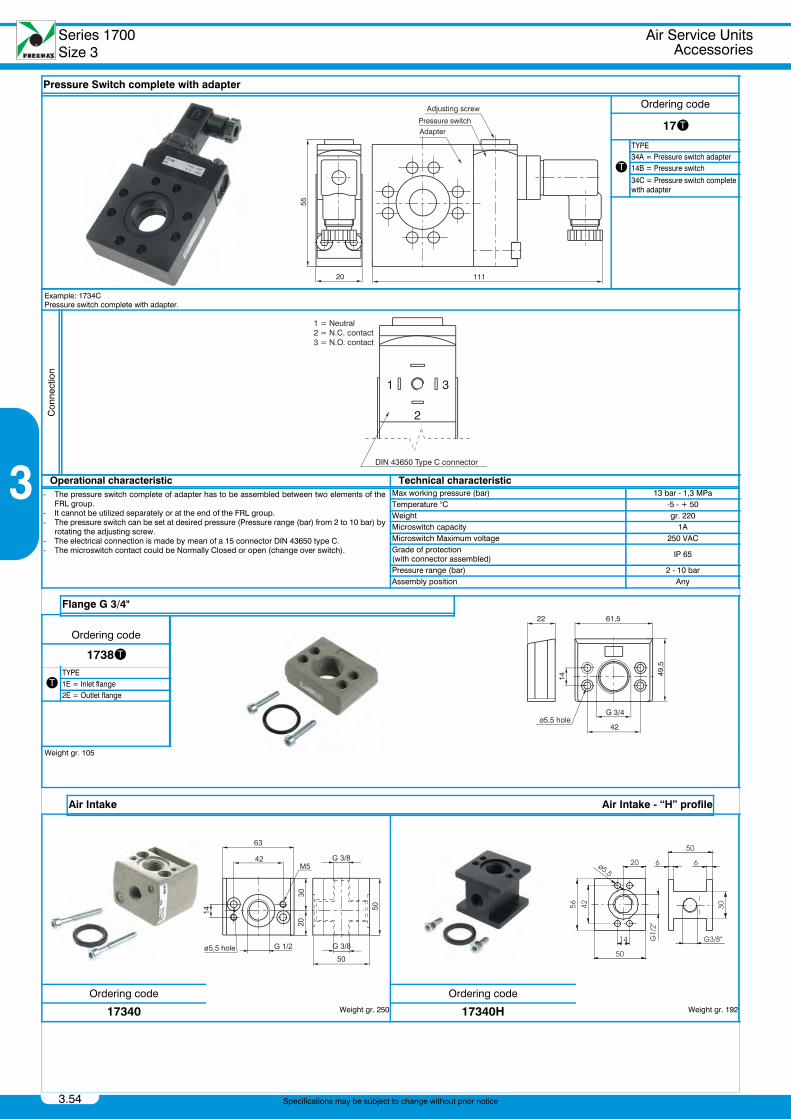
Pressure Switch complete with adapter
Ordering code
17t
t
TYPE34A = Pressure switch adapter14B = Pressure switch
34C = Pressure switch complete with adapter
Example: 1734CPressure switch complete with adapter.
Con
nect
ion
Operational characteristic Technical characteristic- The pressure switch complete of adapter has to be assembled between two elements of the
FRL group.- It cannot be utilized separately or at the end of the FRL group.- The pressure switch can be set at desired pressure (Pressure range (bar) from 2 to 10 bar) by
rotating the adjusting screw.- The electrical connection is made by mean of a 15 connector DIN 43650 type C.- The microswitch contact could be Normally Closed or open (change over switch).
Max working pressure (bar) 13 bar - 1,3 MPaTemperature °C -5 - + 50Weight gr. 220Microswitch capacity 1AMicroswitch Maximum voltage 250 VACGrade of protection(with connector assembled) IP 65
Pressure range (bar) 2 - 10 barAssembly position Any
Flange G 3/4"
Ordering code
1738t
tTYPE1E = Inlet flange2E = Outlet flange
Weight gr. 105
Air Intake Air Intake - “H” profile
Ordering code
Ordering code
17340 Weight gr. 250 17340H Weight gr. 192
PneumaxCatalogo 2012 Capitolo3_GB.book Page 54 Thursday, June 27, 2013 1:26 PM
Air Service UnitsAccessories
Serie 1700Size 3
3.55
3
Specifications may be subject to change without prior notice
Air Service UnitsAccessoriesFixing bracket
Air Service UnitsAccessoriesPressure gauge
Air Service UnitsAccessoriesManometer diameter D.23 mm
Air Service UnitsAccessoriesAssembling kit
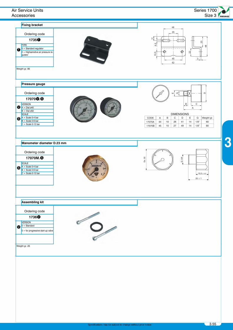
Fixing bracket
Ordering code
1735t
tTYPE0 = Standard regulator
2 = Highsensitive air pressure re-gulator
Weight gr. 85
Pressure gauge
Ordering code
17070v.s
vVERSIONA = Dial ø40B = Dial ø50
sSCALEA = Scale 0-4 barB = Scale 0-6 barC = Scale 0-12 bar
Manometer diameter D.23 mm
Ordering code
17070M.s
sSCALEA = Scale 0-4 barB = Scale 0-6 barC = Scala 0-12 bar
Assembling kit
Ordering code
1736v
vVERSION0 = Standard
5 = for progressive start-up valve
Weight gr. 25
PneumaxCatalogo 2012 Capitolo3_GB.book Page 55 Thursday, June 27, 2013 1:26 PM
s