Overall Layout - Brookhaven National Laboratory Field mapping should be done as part of factory...
34
1
-
Upload
nguyenkhue -
Category
Documents
-
view
220 -
download
8
Transcript of Overall Layout - Brookhaven National Laboratory Field mapping should be done as part of factory...
1
Low Energy RHIC electron Cooling
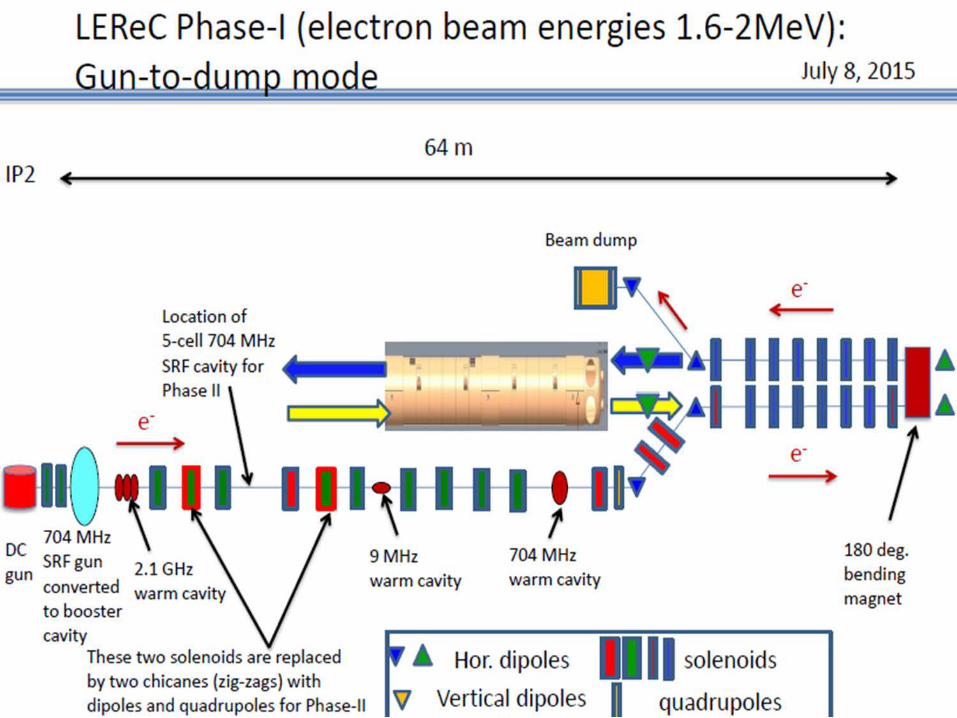
Overall Layout
2
IP264 m
LEReC-I (1.6-2MeV): Gun to dumpSRF gun used as a booster cavity
Move BPM close to 180 magnet combine with PM.Add Quad and Skew Quad Correctors
H & V Correctors
Add Quad and Skew Quad Correctors
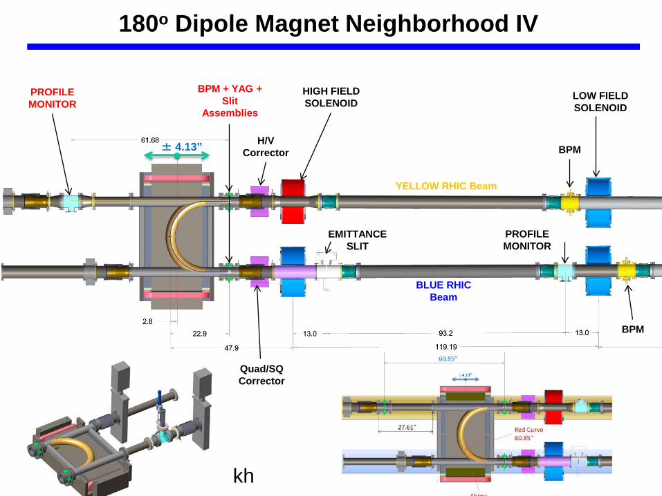
Quad/SQCorrector
± 4.13”
EMITTANCE SLIT
PROFILE MONITOR
LOW FIELD SOLENOID
HIGH FIELD SOLENOID
kh
BPM
BPM
BPM + YAG + Slit
Assemblies
PROFILE MONITOR
BLUE RHIC Beam
YELLOW RHIC Beam
180o Dipole Magnet Neighborhood IV
H/VCorrector
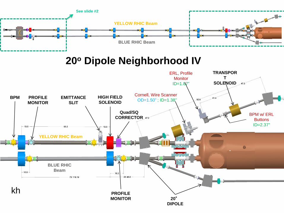
See slide #2
EMITTANCE SLIT
BPM PROFILE MONITOR
HIGH FIELD SOLENOID
20°DIPOLE
kh
Quad/SQCORRECTOR
PROFILE MONITOR
BLUE RHIC Beam
YELLOW RHIC Beam
BLUE RHIC Beam
YELLOW RHIC Beam
TRANSPORT
SOLENOID
Cornell, Wire ScannerOD=1.50” ; ID=1.38’’
ERL, Profile Monitor
ID=1.87”
BPM w/ ERL ButtonsID=2.37”
20o Dipole Neighborhood IV
Low Energy RHIC electron Cooling
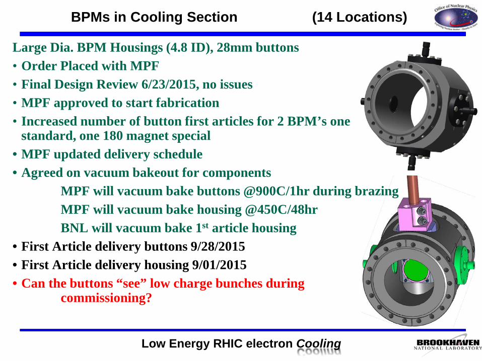
Large Dia. BPM Housings (4.8 ID), 28mm buttons• Order Placed with MPF• Final Design Review 6/23/2015, no issues• MPF approved to start fabrication • Increased number of button first articles for 2 BPM’s one
standard, one 180 magnet special• MPF updated delivery schedule• Agreed on vacuum bakeout for components
MPF will vacuum bake buttons @900C/1hr during brazingMPF will vacuum bake housing @450C/48hrBNL will vacuum bake 1st article housing
• First Article delivery buttons 9/28/2015• First Article delivery housing 9/01/2015• Can the buttons “see” low charge bunches during
commissioning?
BPMs in Cooling Section (14 Locations)
Low Energy RHIC electron Cooling
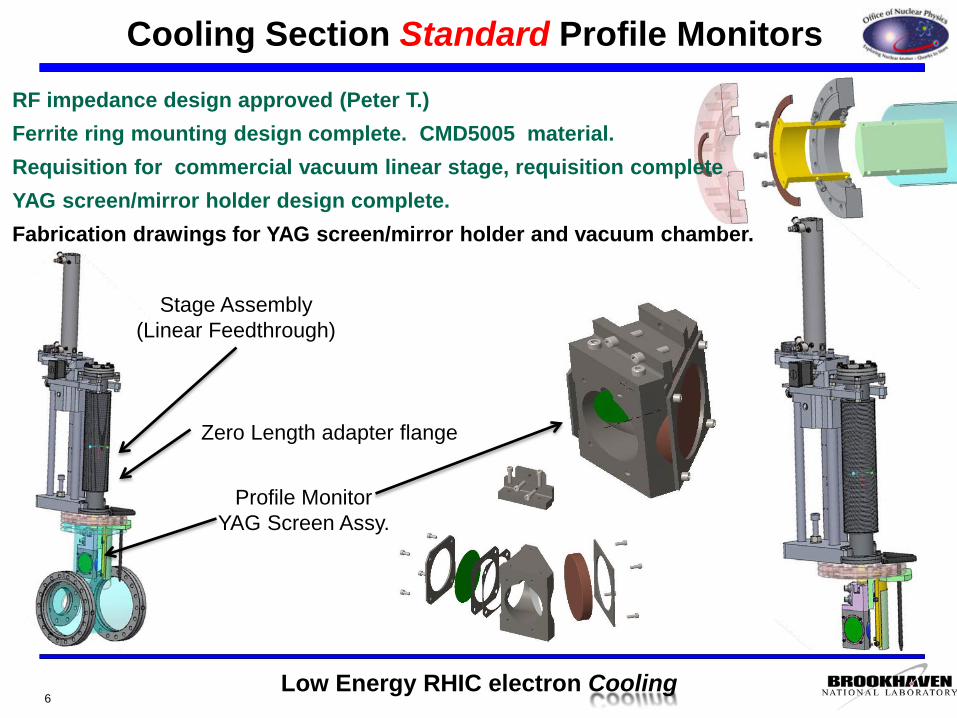
Cooling Section Standard Profile Monitors
6
RF impedance design approved (Peter T.)Ferrite ring mounting design complete. CMD5005 material.Requisition for commercial vacuum linear stage, requisition completeYAG screen/mirror holder design complete.Fabrication drawings for YAG screen/mirror holder and vacuum chamber.
Stage Assembly(Linear Feedthrough)
Zero Length adapter flange
Profile MonitorYAG Screen Assy.
Low Energy RHIC electron Cooling
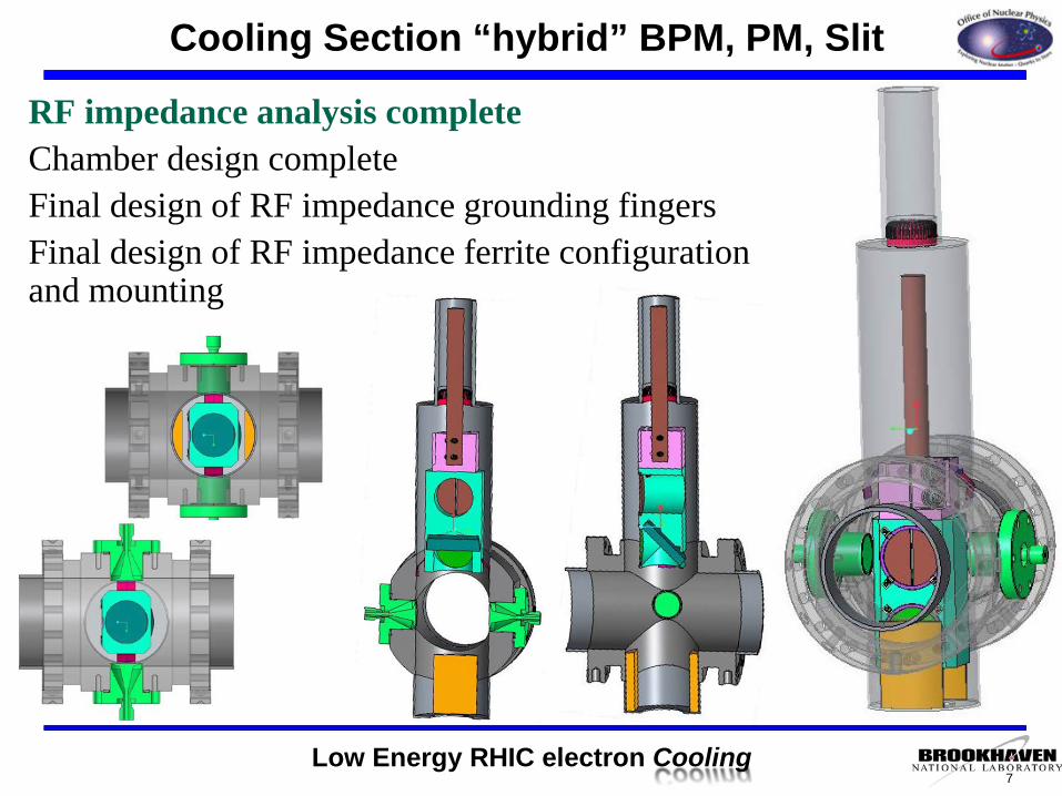
RF impedance analysis completeChamber design completeFinal design of RF impedance grounding fingersFinal design of RF impedance ferrite configuration and mounting
Cooling Section “hybrid” BPM, PM, Slit
7
Low Energy RHIC electron Cooling
Notes:• Mirror thickness specified• Both Hybrids PM, Slit, BPM systems will be 3 position vacuum translating stage drives. The second
hybrid will substitute the slit position (which is not needed) for a fault study beam stop.• Dan transverse position accuracy of the vacuum translating stage – will order 2 and measure.• Joe will order angle mount windows welded 4.5 flange for all of the cooling section profile monitors +
1 spare (7 units).• The windows will be coated with a thin metallic coating to disparate charge. Dan Steski can do it for
us. • Dan will submit all drawings available to CS for cost estimate before he goes on vacation (reference
Gary and Joe on the RFQ)?• The grounding requirements for the hybrid head has been revised. Now the head must be ground to the
sliding fingers in all three positions. It was agreed that the only way to do this was on the sides of the instrument head transverse to the beam as shown below.
• The standard profile monitor will be modified for grounding fingers in the inserted position.• The emittance slits need grounding fingers – a new concern as a result of this meeting.
Cooling Section PM meeting
8
Low Energy RHIC electron Cooling
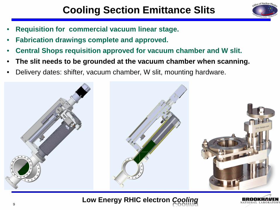
Cooling Section Emittance Slits
9
• Requisition for commercial vacuum linear stage.• Fabrication drawings complete and approved.• Central Shops requisition approved for vacuum chamber and W slit.• The slit needs to be grounded at the vacuum chamber when scanning.• Delivery dates: shifter, vacuum chamber, W slit, mounting hardware.
Low Energy RHIC electron Cooling
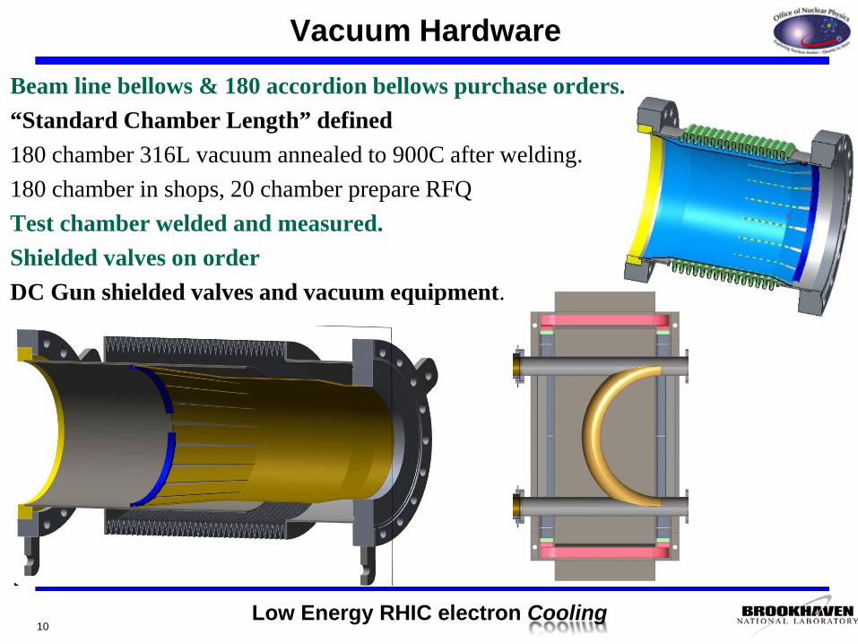
Beam line bellows & 180 accordion bellows purchase orders.“Standard Chamber Length” defined180 chamber 316L vacuum annealed to 900C after welding.180 chamber in shops, 20 chamber prepare RFQTest chamber welded and measured. Shielded valves on orderDC Gun shielded valves and vacuum equipment.
Vacuum Hardware
10
Low Energy RHIC electron Cooling
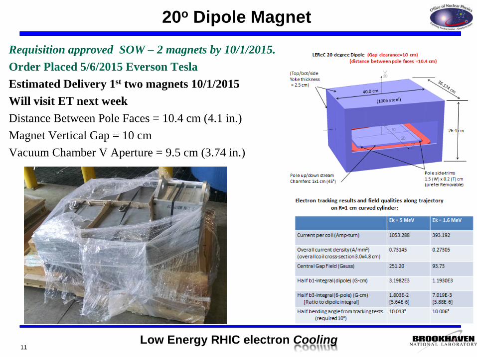
20o Dipole Magnet
11
Requisition approved SOW – 2 magnets by 10/1/2015.Order Placed 5/6/2015 Everson TeslaEstimated Delivery 1st two magnets 10/1/2015Will visit ET next weekDistance Between Pole Faces = 10.4 cm (4.1 in.)Magnet Vertical Gap = 10 cmVacuum Chamber V Aperture = 9.5 cm (3.74 in.)
Low Energy RHIC electron Cooling
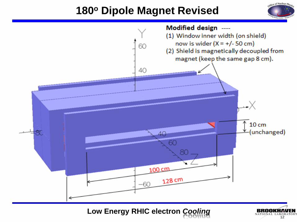
180o Dipole Magnet Revised
12
13
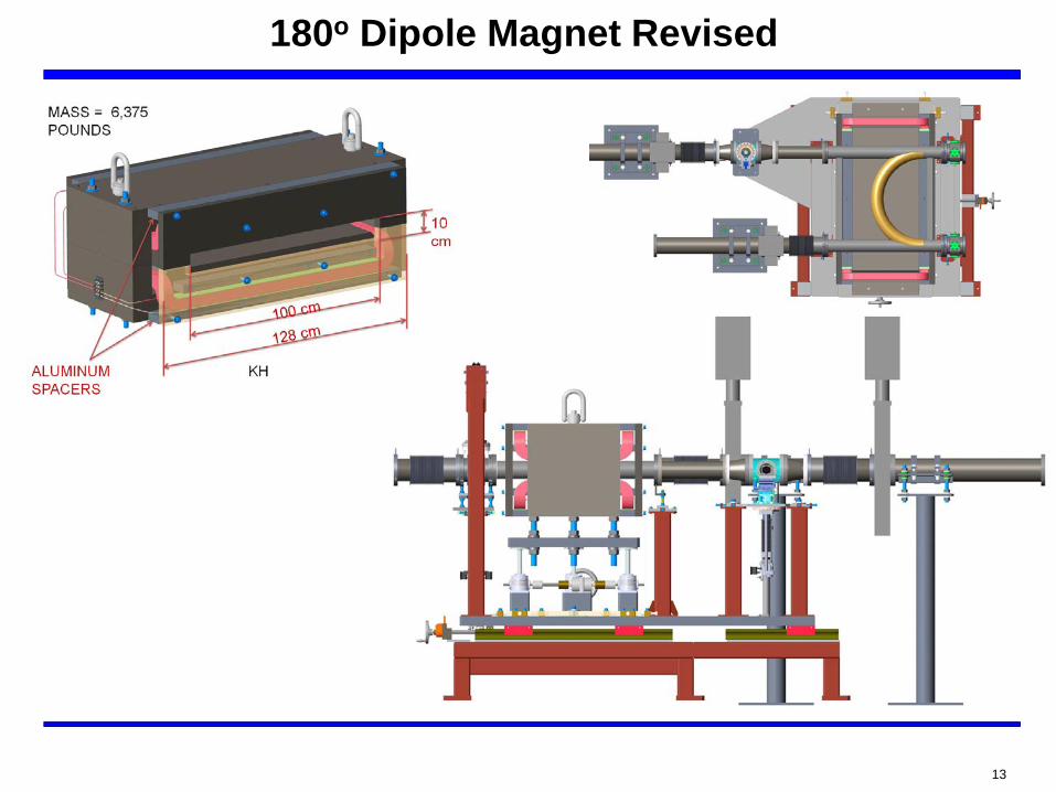
180o Dipole Magnet Revised
Low Energy RHIC electron Cooling14
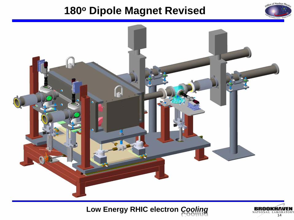
180o Dipole Magnet Revised
Low Energy RHIC electron Cooling
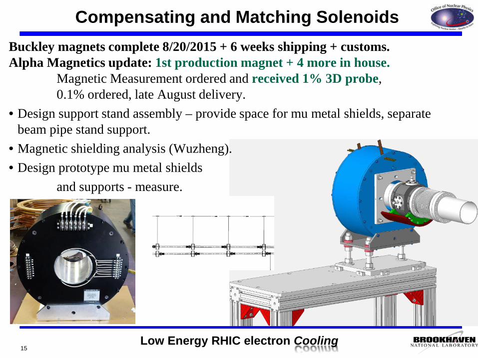
Buckley magnets complete 8/20/2015 + 6 weeks shipping + customs.Alpha Magnetics update: 1st production magnet + 4 more in house.
Magnetic Measurement ordered and received 1% 3D probe, 0.1% ordered, late August delivery.
• Design support stand assembly – provide space for mu metal shields, separate beam pipe stand support.
• Magnetic shielding analysis (Wuzheng).• Design prototype mu metal shields
and supports - measure.
Compensating and Matching Solenoids
15
Low Energy RHIC electron Cooling
Compensating Solenoids Measurement
16
Here is Animesh’s brief description of the measurements that need to be made. Hecommented in an earlier email that it would take more than 2 days to complete themeasurements. (My guess: a week for the first complete set of measurements.) He hasbeen given no specific guidance from Alexei about details of the measurement plan.
“There are actually 3 solenoids in it and they need to be measured separately and alsopowered together to determine if all the desired characteristics can be met, and what theoptimum powering configuration is. This is going to take time. There are also dipolecorrectors which we cannot measure with the reoriented Hall probe. Those must bemeasured with a mole. Also, they are interested in the integrated harmonics of thesolenoid.”
Animesh will be away 11 days starting Weds. of next week, so that if the data from nextMon and Tues are insufficient for acceptance testing, the next data are ~ two weeksaway. I propose an acceptance plan as follows: Hall probe scan of the three solenoids,one at a time, step size chosen so that the measurements are completed in a day. 2nd
day: complete Hall probe measurements as needed, followed by mole measurements ofthe two(?) correctors, powered independently. It is not clear to me that all this can bedone in two days, but if so, are you interested in this reduced set in order to getproduction rolling?
Peter Wanderer
Low Energy RHIC electron Cooling
Matching Solenoids Vendor Measurement
17
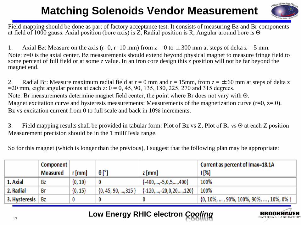
Field mapping should be done as part of factory acceptance test. It consists of measuring Bz and Br components at field of 1000 gauss. Axial position (bore axis) is Z, Radial position is R, Angular around bore is Θ
1. Axial Bz: Measure on the axis (r=0, r=10 mm) from z = 0 to ±300 mm at steps of delta z = 5 mm.Note: z=0 is the axial center. Bz measurements should extend beyond physical magnet to measure fringe field to some percent of full field or at some z value. In an iron core design this z position will not be far beyond the magnet end.
2. Radial Br: Measure maximum radial field at r = 0 mm and r = 15mm, from z = ±60 mm at steps of delta z =20 mm, eight angular points at each z: θ = 0, 45, 90, 135, 180, 225, 270 and 315 degrees.Note: Br measurements determine magnet field center, the point where Br does not vary with Θ.Magnet excitation curve and hysteresis measurements: Measurements of the magnetization curve (r=0, z= 0). Bz vs excitation current from 0 to full scale and back in 10% increments.
3. Field mapping results shall be provided in tabular form: Plot of Bz vs Z, Plot of Br vs Θ at each Z positionMeasurement precision should be in the 1 milliTesla range.
So for this magnet (which is longer than the previous), I suggest that the following plan may be appropriate:
Low Energy RHIC electron Cooling
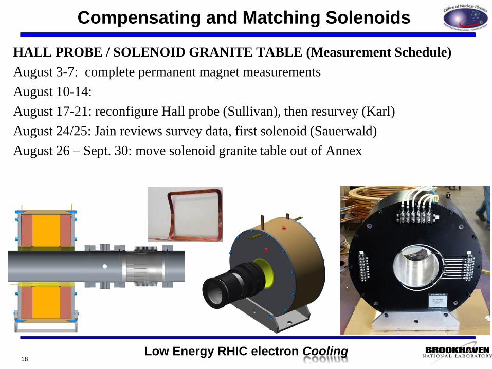
HALL PROBE / SOLENOID GRANITE TABLE (Measurement Schedule)August 3-7: complete permanent magnet measurementsAugust 10-14: August 17-21: reconfigure Hall probe (Sullivan), then resurvey (Karl)August 24/25: Jain reviews survey data, first solenoid (Sauerwald)August 26 – Sept. 30: move solenoid granite table out of Annex
Compensating and Matching Solenoids
18
Low Energy RHIC electron Cooling
LEReC Cooling Section Design Room
19
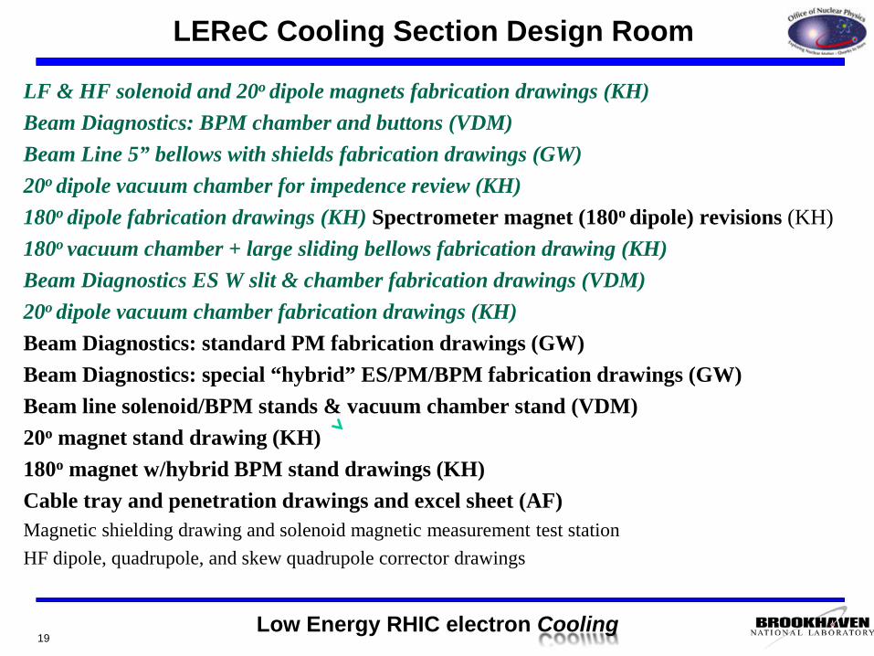
LF & HF solenoid and 20o dipole magnets fabrication drawings (KH)Beam Diagnostics: BPM chamber and buttons (VDM)Beam Line 5” bellows with shields fabrication drawings (GW)20o dipole vacuum chamber for impedence review (KH)180o dipole fabrication drawings (KH) Spectrometer magnet (180o dipole) revisions (KH)180o vacuum chamber + large sliding bellows fabrication drawing (KH)Beam Diagnostics ES W slit & chamber fabrication drawings (VDM)20o dipole vacuum chamber fabrication drawings (KH)Beam Diagnostics: standard PM fabrication drawings (GW)Beam Diagnostics: special “hybrid” ES/PM/BPM fabrication drawings (GW)Beam line solenoid/BPM stands & vacuum chamber stand (VDM)20o magnet stand drawing (KH)180o magnet w/hybrid BPM stand drawings (KH)Cable tray and penetration drawings and excel sheet (AF)Magnetic shielding drawing and solenoid magnetic measurement test stationHF dipole, quadrupole, and skew quadrupole corrector drawings
Low Energy RHIC electron Cooling
LEReC Design Room Source Design Work
20
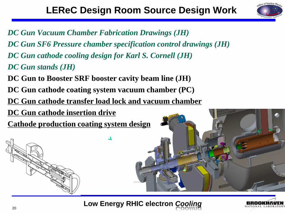
DC Gun Vacuum Chamber Fabrication Drawings (JH)DC Gun SF6 Pressure chamber specification control drawings (JH)DC Gun cathode cooling design for Karl S. Cornell (JH)DC Gun stands (JH)DC Gun to Booster SRF booster cavity beam line (JH)DC Gun cathode coating system vacuum chamber (PC)DC Gun cathode transfer load lock and vacuum chamberDC Gun cathode insertion driveCathode production coating system design
Low Energy RHIC electron Cooling
LEReC Design Room Other Work
21
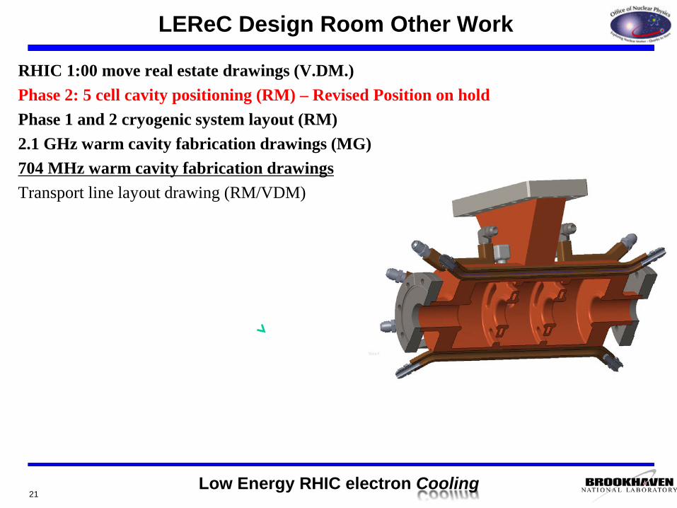
RHIC 1:00 move real estate drawings (V.DM.)Phase 2: 5 cell cavity positioning (RM) – Revised Position on holdPhase 1 and 2 cryogenic system layout (RM)2.1 GHz warm cavity fabrication drawings (MG)704 MHz warm cavity fabrication drawingsTransport line layout drawing (RM/VDM)
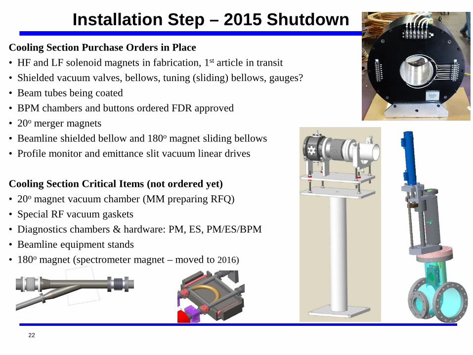
Cooling Section Purchase Orders in Place• HF and LF solenoid magnets in fabrication, 1st article in transit• Shielded vacuum valves, bellows, tuning (sliding) bellows, gauges?• Beam tubes being coated• BPM chambers and buttons ordered FDR approved • 20o merger magnets • Beamline shielded bellow and 180o magnet sliding bellows• Profile monitor and emittance slit vacuum linear drives
Cooling Section Critical Items (not ordered yet) • 20o magnet vacuum chamber (MM preparing RFQ)• Special RF vacuum gaskets• Diagnostics chambers & hardware: PM, ES, PM/ES/BPM• Beamline equipment stands• 180o magnet (spectrometer magnet – moved to 2016)
22
Installation Step – 2015 Shutdown
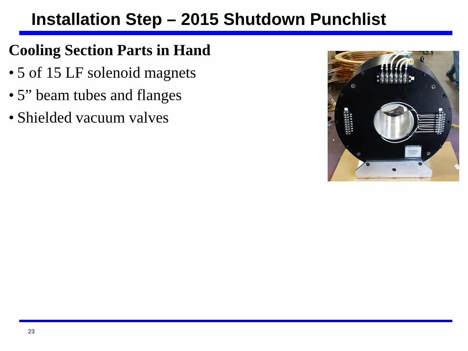
Cooling Section Parts in Hand• 5 of 15 LF solenoid magnets• 5” beam tubes and flanges• Shielded vacuum valves
23
Installation Step – 2015 Shutdown Punchlist
Reference Slides
24
Low Energy RHIC electron Cooling
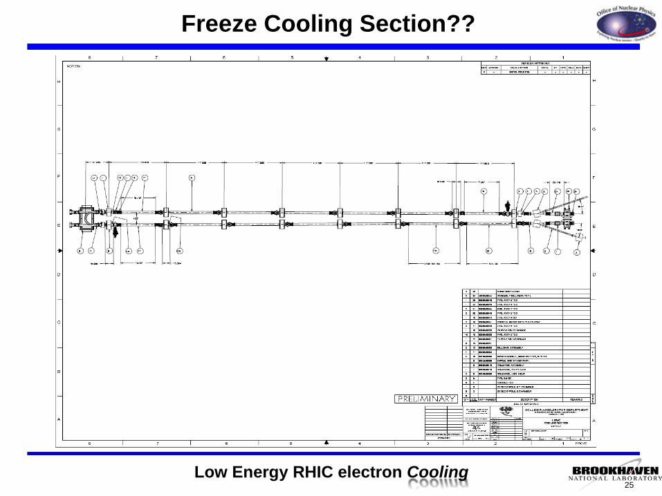
Freeze Cooling Section??
25
Low Energy RHIC electron Cooling
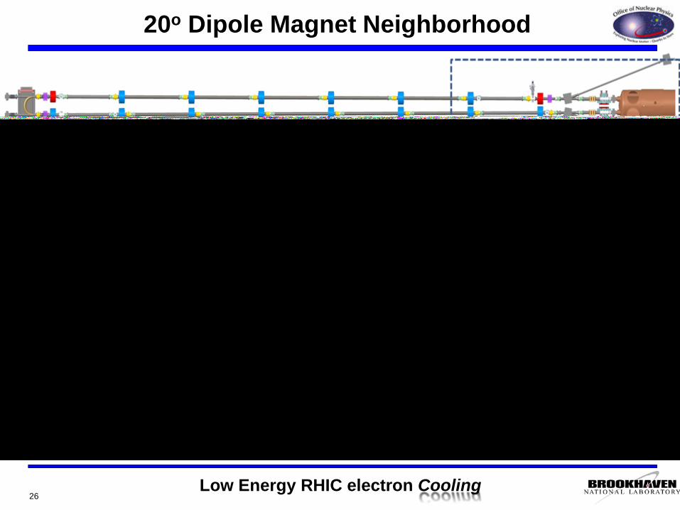
20o Dipole Magnet Neighborhood
26

Low Energy RHIC electron Cooling27
180o Dipole Magnet Neighborhood II
Aperture Transitions

Low Energy RHIC electron Cooling
5 cell cavity location
28
New updates?
5 cell

Low Energy RHIC electron Cooling
Requisition Status
Range of motion for magnet core +/- 10cm.Magnet Vertical Gap = 10.0 cm (3.94 in.)Vacuum Chamber Aperture = 9.5 cm (3.75 in.)
180o Dipole Magnet
29
Low Energy RHIC electron Cooling
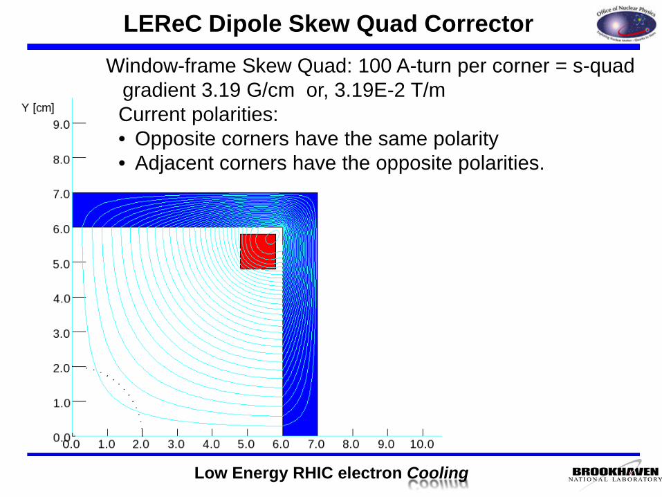
Window-frame Skew Quad: 100 A-turn per corner = s-quad gradient 3.19 G/cm or, 3.19E-2 T/mCurrent polarities:• Opposite corners have the same polarity• Adjacent corners have the opposite polarities.
LEReC Dipole Skew Quad Corrector
Low Energy RHIC electron Cooling
14.8
5.08 16.84
1.27 cm (thickness)
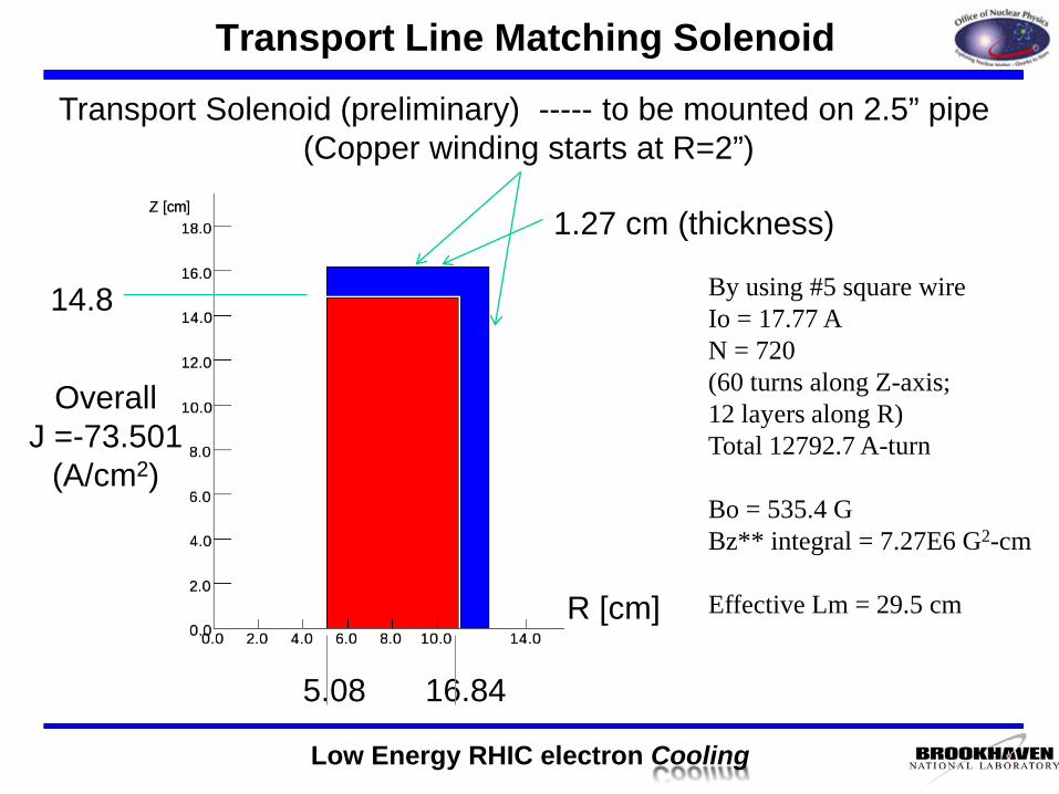
Transport Solenoid (preliminary) ----- to be mounted on 2.5” pipe (Copper winding starts at R=2”)
By using #5 square wireIo = 17.77 AN = 720(60 turns along Z-axis;12 layers along R)Total 12792.7 A-turn
Bo = 535.4 GBz** integral = 7.27E6 G2-cm
Effective Lm = 29.5 cmR [cm]
OverallJ =-73.501
(A/cm2)
Transport Line Matching Solenoid
Low Energy RHIC electron Cooling
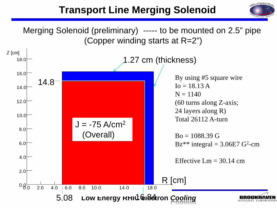
J = -75 A/cm2
(Overall)
14.8
5.08 16.84
1.27 cm (thickness)
Merging Solenoid (preliminary) ----- to be mounted on 2.5” pipe (Copper winding starts at R=2”)
By using #5 square wireIo = 18.13 AN = 1140(60 turns along Z-axis;24 layers along R)Total 26112 A-turn
Bo = 1088.39 GBz** integral = 3.06E7 G2-cm
Effective Lm = 30.14 cm
R [cm]
Transport Line Merging Solenoid
Low Energy RHIC electron Cooling
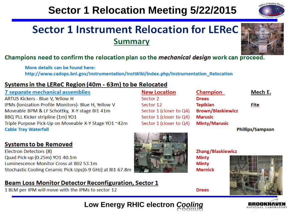
Sector 1 Relocation Meeting 5/22/2015
Low Energy RHIC electron Cooling
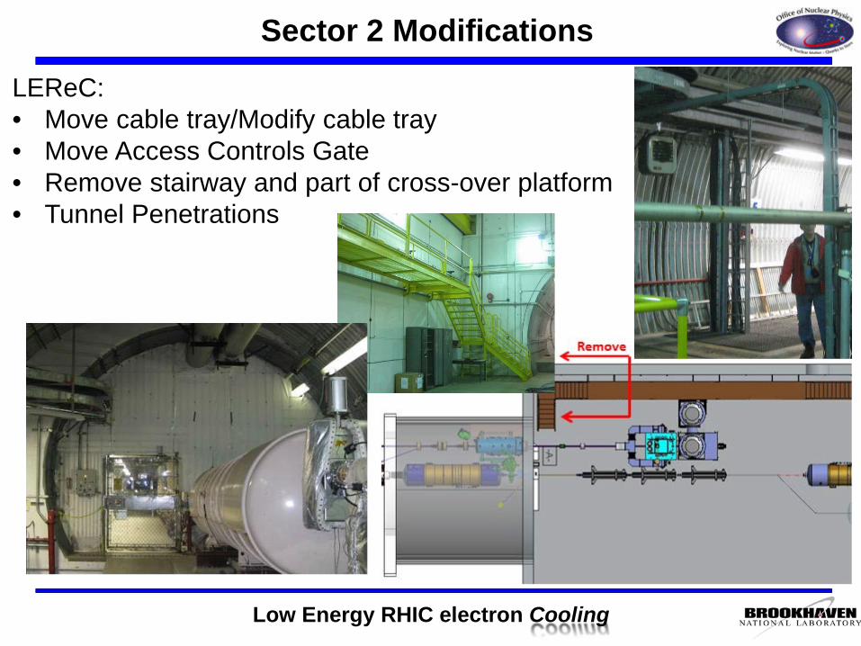
Sector 2 Modifications
LEReC:• Move cable tray/Modify cable tray• Move Access Controls Gate• Remove stairway and part of cross-over platform• Tunnel Penetrations


![Acceptance Rates (1) (black) Linst-mat.utalca.cl/jornadasbioestadistica2011/doc...Monte Carlo Methods with R: Metropolis–Hastings Algorithms [160] Acceptance Rates Normals from Double](https://static.fdocument.org/doc/165x107/6147bd3eafbe1968d37a3eb9/acceptance-rates-1-black-linst-mat-monte-carlo-methods-with-r-metropolisahastings.jpg)