Other antennas Feed Lines - t Upongsak.ee.engr.tu.ac.th/le428/misc.pdf · • Other antennas •...
54
1 Miscellaneous Topics • Folded dipole antenna • Special antennas – Yagi-Uda antenna – Broadband antenna – Log-periodic antenna • Other antennas • Feed Lines
Transcript of Other antennas Feed Lines - t Upongsak.ee.engr.tu.ac.th/le428/misc.pdf · • Other antennas •...
1
Miscellaneous Topics
• Folded dipole antenna
• Special antennas
– Yagi-Uda antenna
– Broadband antenna
– Log-periodic antenna
• Other antennas
• Feed Lines

Folded Dipole
2
• Half-wavelength dipoles have impedance 73+j42.5 ΩΩΩΩ
• Typical transmission line : 50 or 75 Ω Ω Ω Ω
• Twin-lead transmission line has impedance 300 ΩΩΩΩ
• Folded dipole is one way to match 300 ΩΩΩΩ
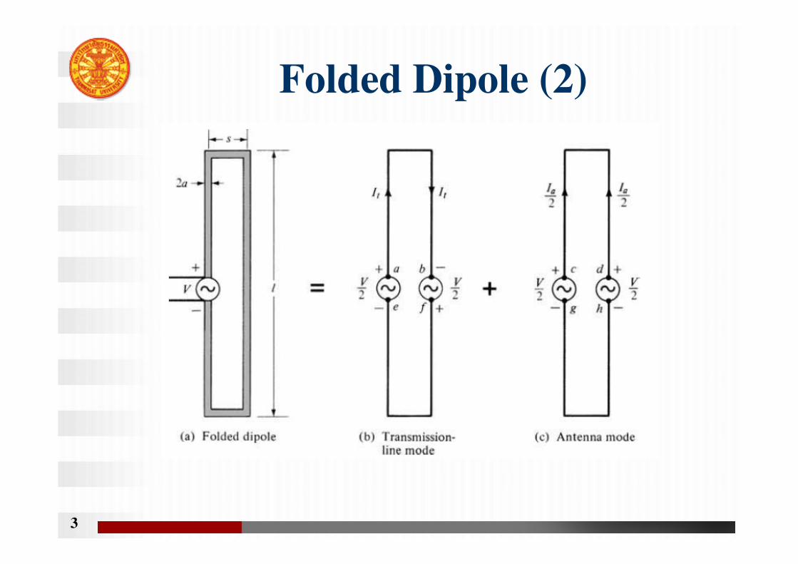
Folded Dipole (2)
3
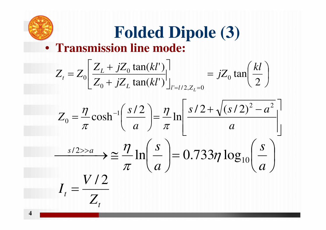
Folded Dipole (3)• Transmission line mode:
4
=
++
===
2tan
)'tan(
)'tan(0
0,2/'0
00
kljZ
kljZZ
kljZZZZ
LZllL
Lt
−+=
= −
a
ass
a
sZ
22
1
0
)2/(2/ln
2/cosh
πη
πη
=
≅ → >>
a
s
a
sas
10
2/log733.0ln η
πη
t
tZ
VI
2/=
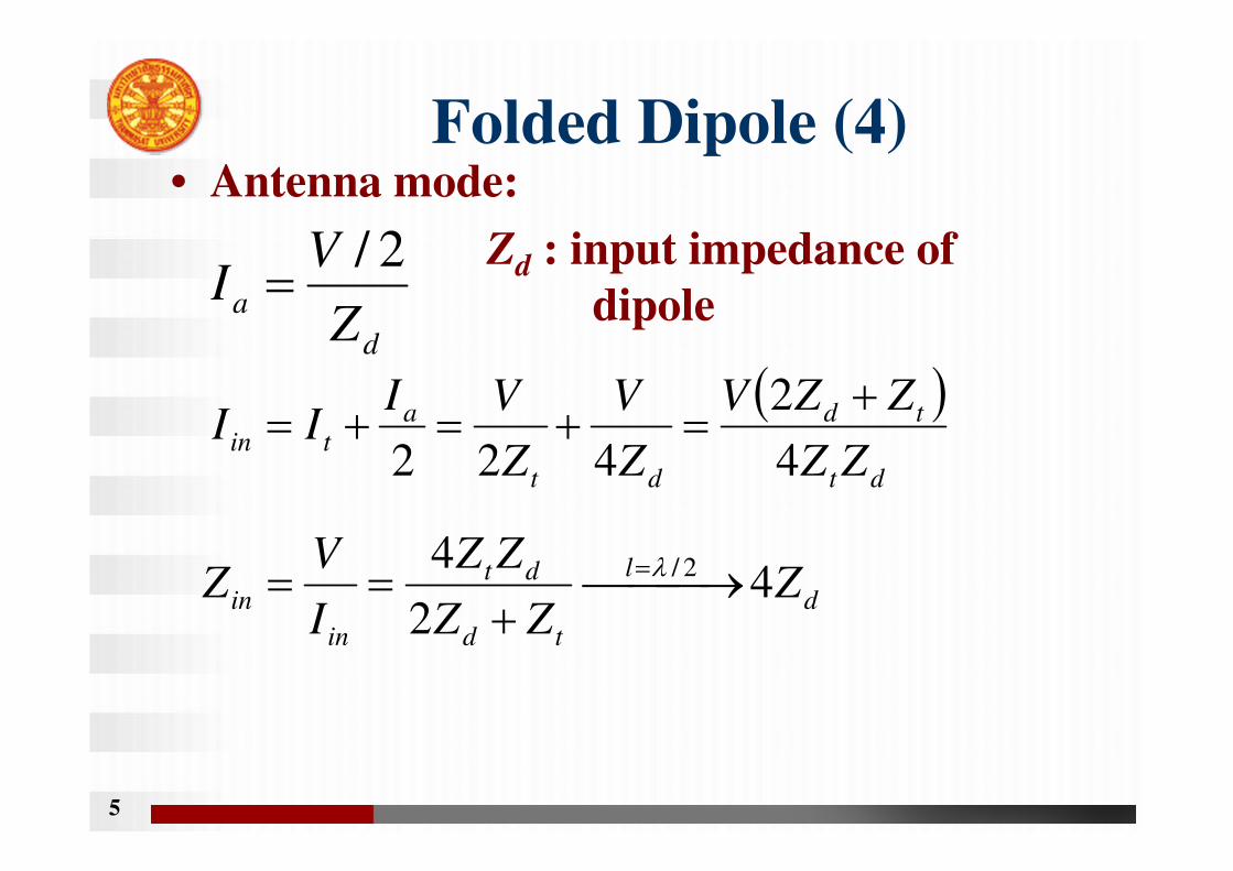
Folded Dipole (4)• Antenna mode:
Zd : input impedance of
dipole
5
d
aZ
VI
2/=
( )dt
td
dt
atin
ZZ
ZZV
Z
V
Z
VIII
4
2
422
+=+=+=
d
l
td
dt
in
in ZZZ
ZZ
I
VZ 4
2
4 2/ →+
== =λ
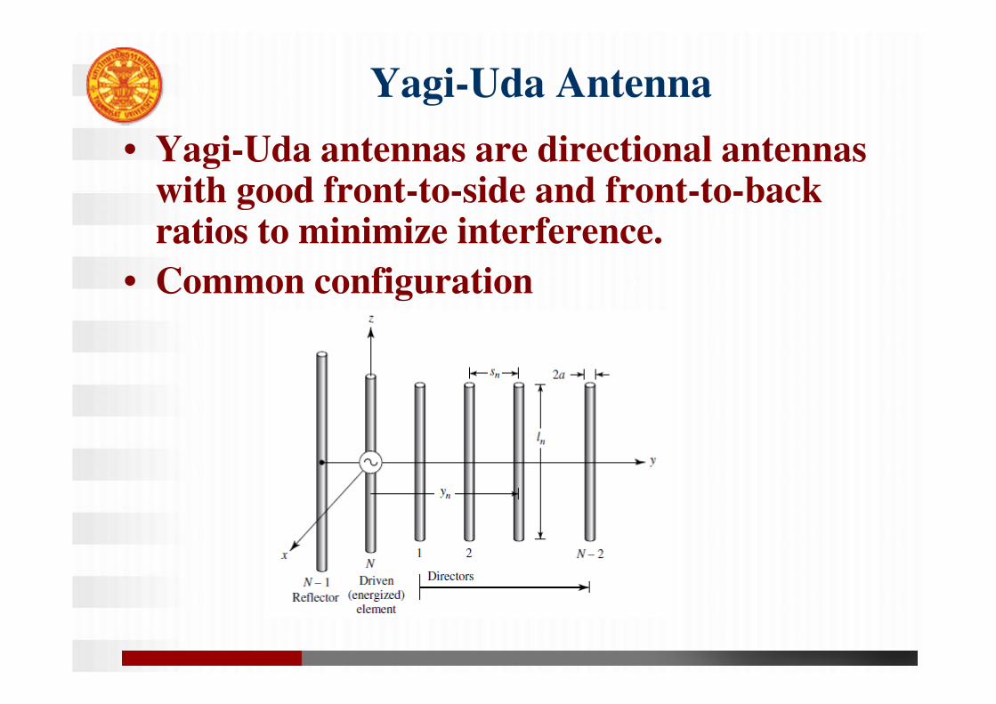
• Yagi-Uda antennas are directional antennas with good front-to-side and front-to-back ratios to minimize interference.
• Common configuration
Yagi-Uda Antenna
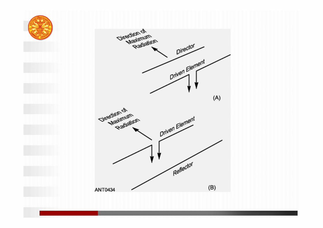
• A Yagi is a parasitic array antenna made up of two or more elements. The main lobe is in the forward direction of the Yagi.
– The driven element is an approximately ½ wave dipole or folded dipole.
– The reflector is a parasitic element behind the driven element (opposite the direction of the main lobe), and is a bit longer than the driven element.
– The director is a parasitic element in front of the driven element, and is a bit shorter than the driven element.
– A three element Yagi has a theoretical gain of 9.7 dBi and front-to-back ratio of 30 to 35 dB.
• Reflector spacing and size have
1. Negligible effects on forward gain
2. Large effects on backward gain (Front-
to-back ratio) and input impedance.
• Feeder size and radius control input
impedance, which is usually made real
(resonant element)
• Director spacing and size have large
effects on forward gain, backward gain
and input impedance.
9
• A Yagi can have additional directors to
increase gain, but the gain is limited.
• Larger diameter elements improves the
bandwidth of at Yagi. This is also true for
other antennas.
• Element spacing, boom length, and the
number of elements all affect the SWR and
performance of a Yagi.
• Yagi antennas have a feed point impedance
of around 20 to 25 ohms.
Need impedance matching.
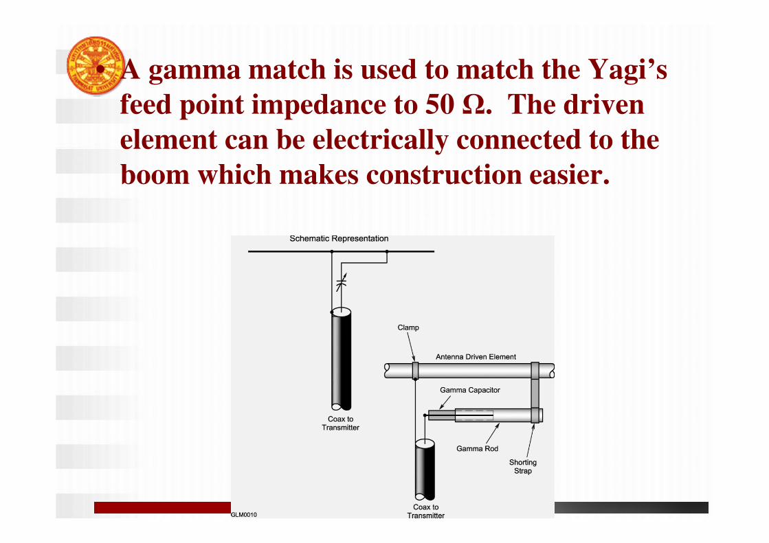
• A gamma match is used to match the Yagi’s
feed point impedance to 50 Ω. The driven
element can be electrically connected to the
boom which makes construction easier.
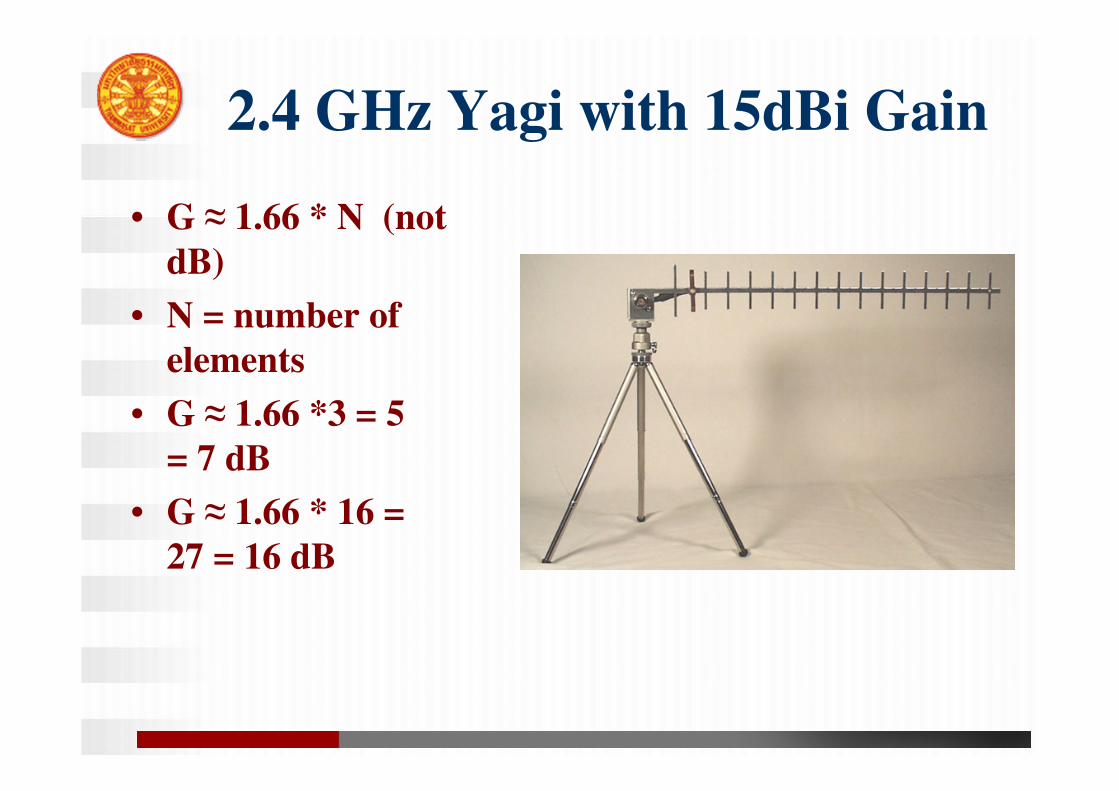
2.4 GHz Yagi with 15dBi Gain
• G ≈ 1.66 * N (not
dB)
• N = number of
elements
• G ≈ 1.66 *3 = 5
= 7 dB
• G ≈ 1.66 * 16 =
27 = 16 dB
Broadband Antennas• Typical antennas are designed for a specific
narrow band of operation
• Sometimes called frequency-independent
antennas.
• Broadband antennas are designed to operate
effectively over a wide range of frequencies
– Public two-way-radio VHF covers 130-174Mhz
– Public two-way-radio UHF 406-512Mhz
– The challenge is to create an antenna which can operate
in both the VHF and UHF bands
• Also crucial for astronomical radio
observations.
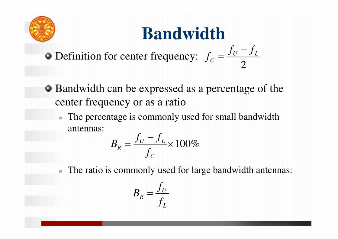
Bandwidth
%100×−
=C
LUP
f
ffB
Definition for center frequency:
Bandwidth can be expressed as a percentage of the
center frequency or as a ratio
The percentage is commonly used for small bandwidth
antennas:
The ratio is commonly used for large bandwidth antennas:
L
UR
f
fB =
2
LUC
fff
−=
L
UR
f
fB =
%100×−
=C
LUR
f
ffB

Broad Spectrum of Types
• Log Periodic
• Helical
• Biconical
• Sleeve
• Spiral
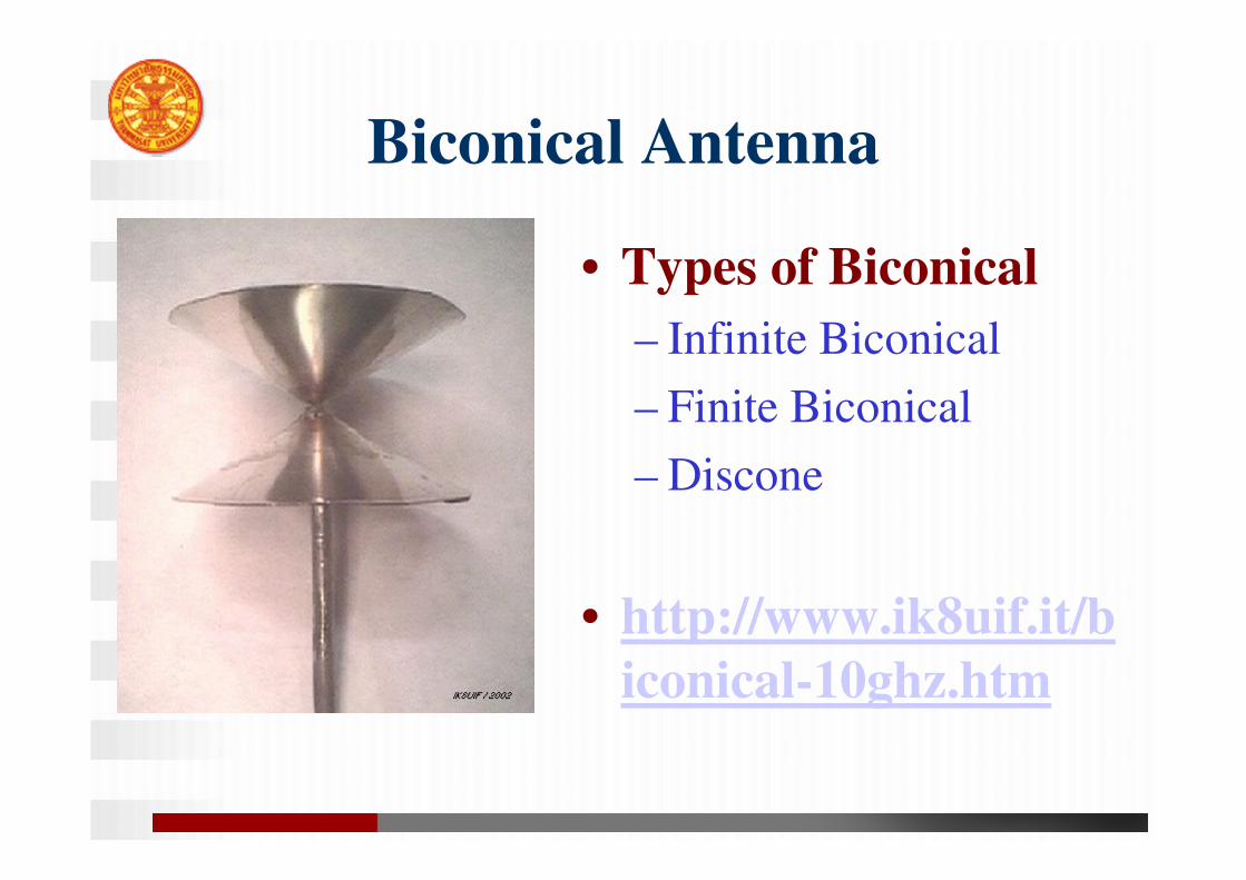
Biconical Antenna
• Types of Biconical
– Infinite Biconical
– Finite Biconical
– Discone
• http://www.ik8uif.it/b
iconical-10ghz.htm
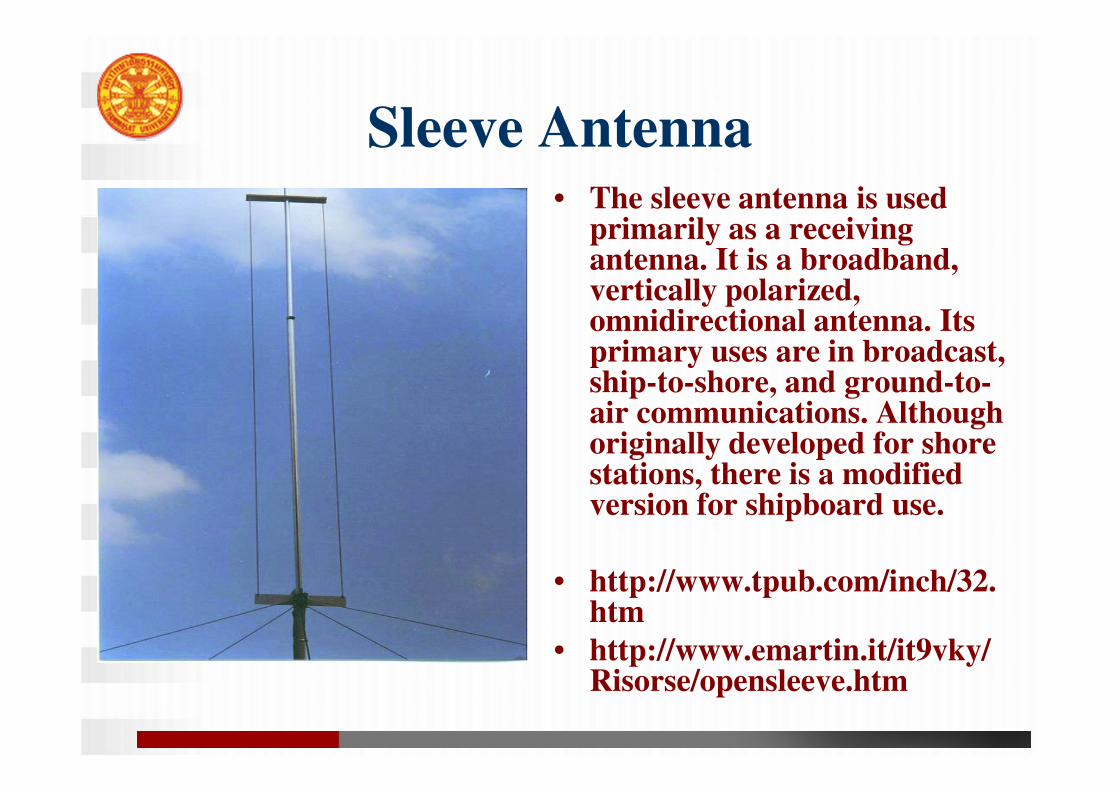
Sleeve Antenna• The sleeve antenna is used
primarily as a receiving antenna. It is a broadband, vertically polarized, omnidirectional antenna. Its primary uses are in broadcast, ship-to-shore, and ground-to-air communications. Although originally developed for shore stations, there is a modified version for shipboard use.
• http://www.tpub.com/inch/32.htm
• http://www.emartin.it/it9vky/Risorse/opensleeve.htm
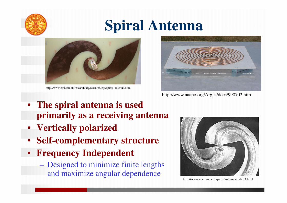
Spiral Antenna
• The spiral antenna is used primarily as a receiving antenna
• Vertically polarized
• Self-complementary structure
• Frequency Independent
– Designed to minimize finite lengths and maximize angular dependence
http://www.naapo.org/Argus/docs/990702.htm
http://www.emi.dtu.dk/research/afg/research/gpr/spiral_antenna.html
http://www.ece.uiuc.edu/pubs/antenna/slide03.html
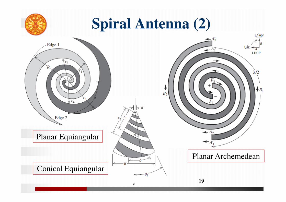
Spiral Antenna (2)
19
Conical Equiangular
Planar Archemedean
Planar Equiangular
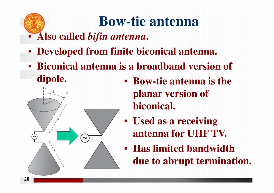
Bow-tie antenna• Also called bifin antenna.
• Developed from finite biconical antenna.
• Biconical antenna is a broadband version of
dipole.
20
• Bow-tie antenna is the
planar version of
biconical.
• Used as a receiving
antenna for UHF TV.
• Has limited bandwidth
due to abrupt termination.
Log-Periodic Antenna
• Modifying the simple bow-tie antenna can
make the current die off more rapidly with
distance from the feed point.
• Thus, introduction of periodically positioned
teeth. -> Log-periodic antenna
• Log-periodic antenna is an antenna having a
structural geometry such that its impedance
and radiation characteristics repeat
periodically as the logarithm of frequency.
21
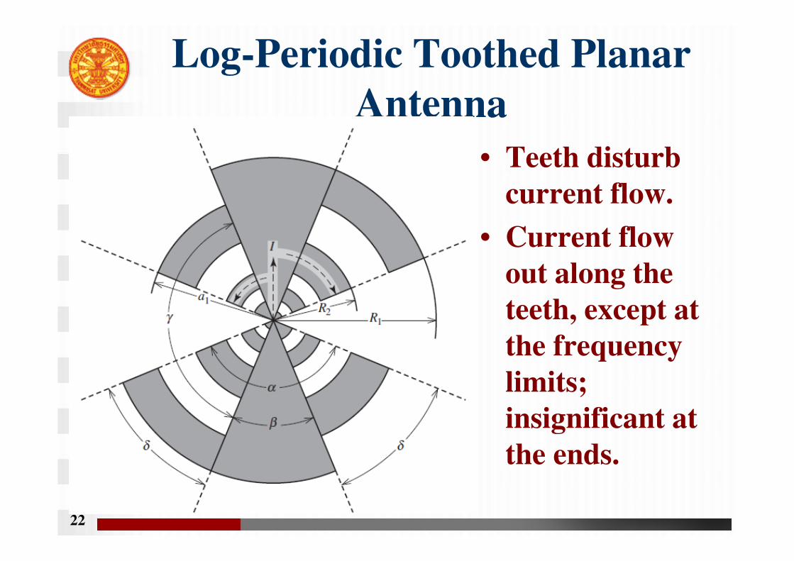
Log-Periodic Toothed Planar
Antenna
• Teeth disturb
current flow.
• Current flow
out along the
teeth, except at
the frequency
limits;
insignificant at
the ends.
22
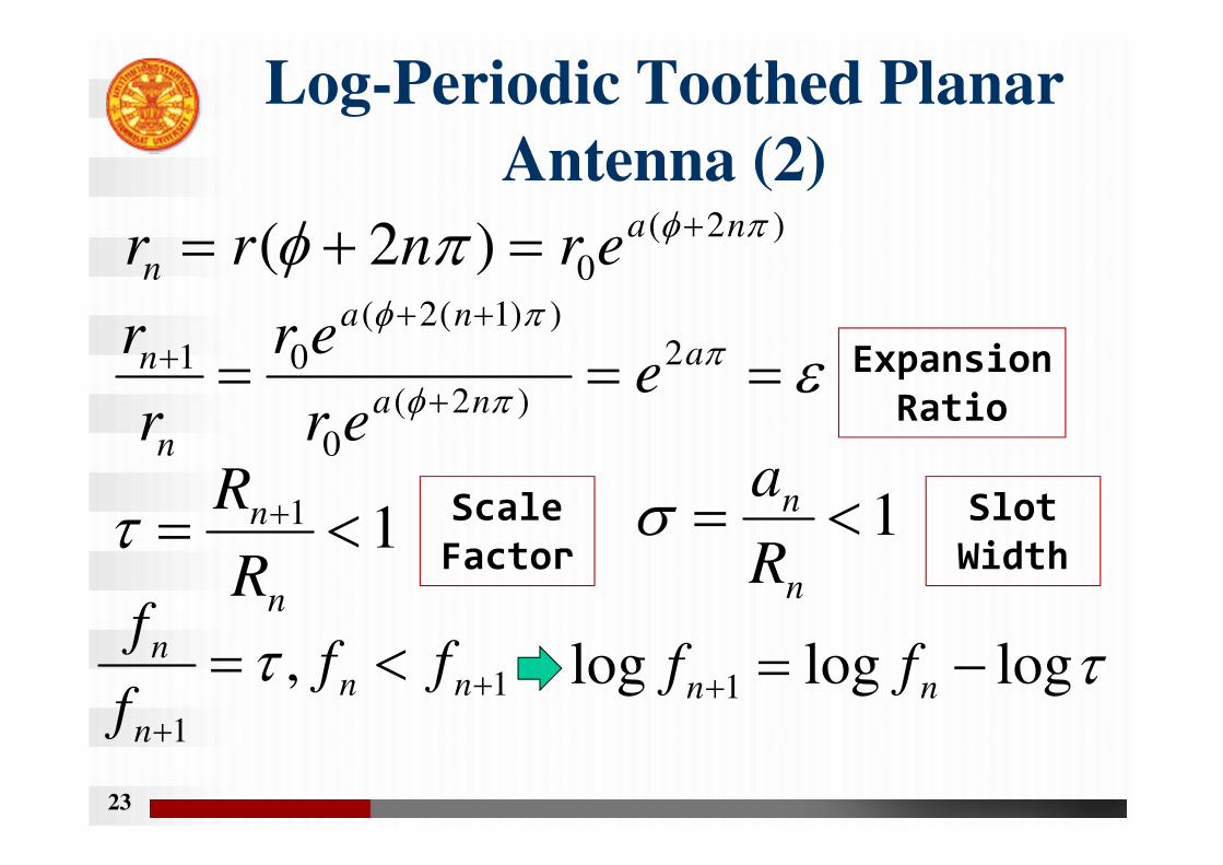
Log-Periodic Toothed Planar
Antenna (2)
23
)2(
0)2( πφπφ na
n ernrr+=+=
εππφ
πφ
===+
+++ a
na
na
n
n eer
er
r
r 2
)2(
0
))1(2(
01 Expansion
Ratio
11 <= +
n
n
R
Rτ Scale
Factor1<=
n
n
R
aσ Slot
Width
1
1
, ++
<= nn
n
n fff
fτ τlogloglog 1 −=+ nn ff
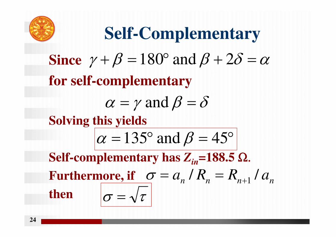
Self-Complementary
Since
for self-complementary
Solving this yields
Self-complementary has Zin=188.5 Ω.Ω.Ω.Ω.
Furthermore, if
then
24
αδββγ =+°=+ 2 and 180
δβγα == and
°=°= 45 and 135 βα
nnnn aRRa // 1+==στσ =
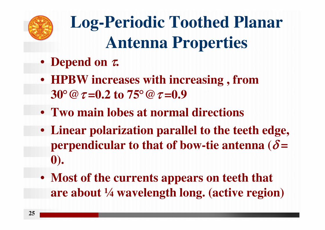
Log-Periodic Toothed Planar
Antenna Properties• Depend on ττττ.
• HPBW increases with increasing , from
30°°°°@τ τ τ τ =0.2 to 75°°°°@τ τ τ τ =0.9
• Two main lobes at normal directions
• Linear polarization parallel to the teeth edge,
perpendicular to that of bow-tie antenna (δ δ δ δ =
0).
• Most of the currents appears on teeth that
are about ¼ wavelength long. (active region)
25
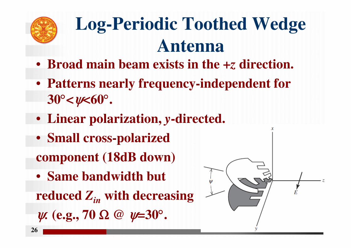
Log-Periodic Toothed Wedge
Antenna• Broad main beam exists in the +z direction.
• Patterns nearly frequency-independent for
30°°°°<ψψψψ<60°°°°.
• Linear polarization, y-directed.
• Small cross-polarized
component (18dB down)
• Same bandwidth but
reduced Zin with decreasing
ψψψψ. (e.g., 70 ΩΩΩΩ @ ψψψψ=30°°°°.26
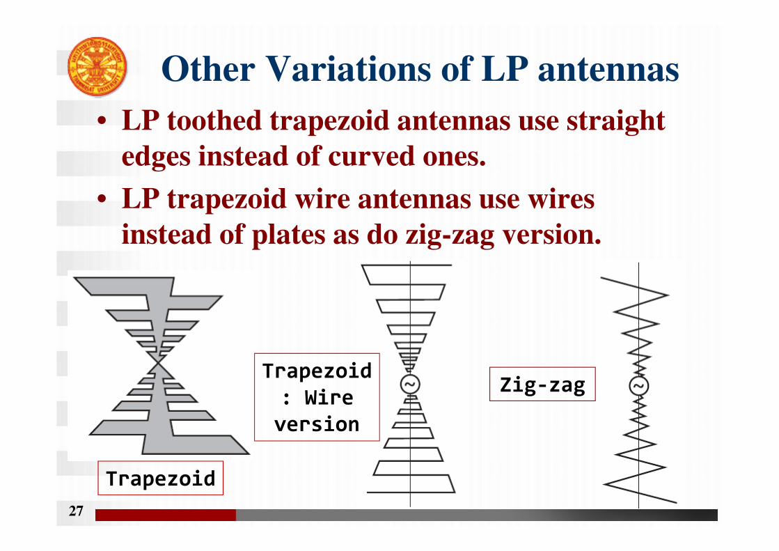
Other Variations of LP antennas
• LP toothed trapezoid antennas use straight
edges instead of curved ones.
• LP trapezoid wire antennas use wires
instead of plates as do zig-zag version.
27
Trapezoid
Trapezoid
: Wire
version
Zig-zag

Log-Periodic Dipole Array
(LPDA)
28
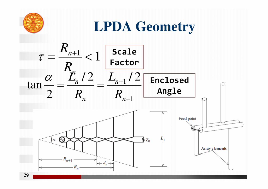
LPDA Geometry
29
11 <= +
n
n
R
Rτ Scale
Factor
1
1 2/2/
2tan
+
+==n
n
n
n
R
L
R
Lα Enclosed
Angle
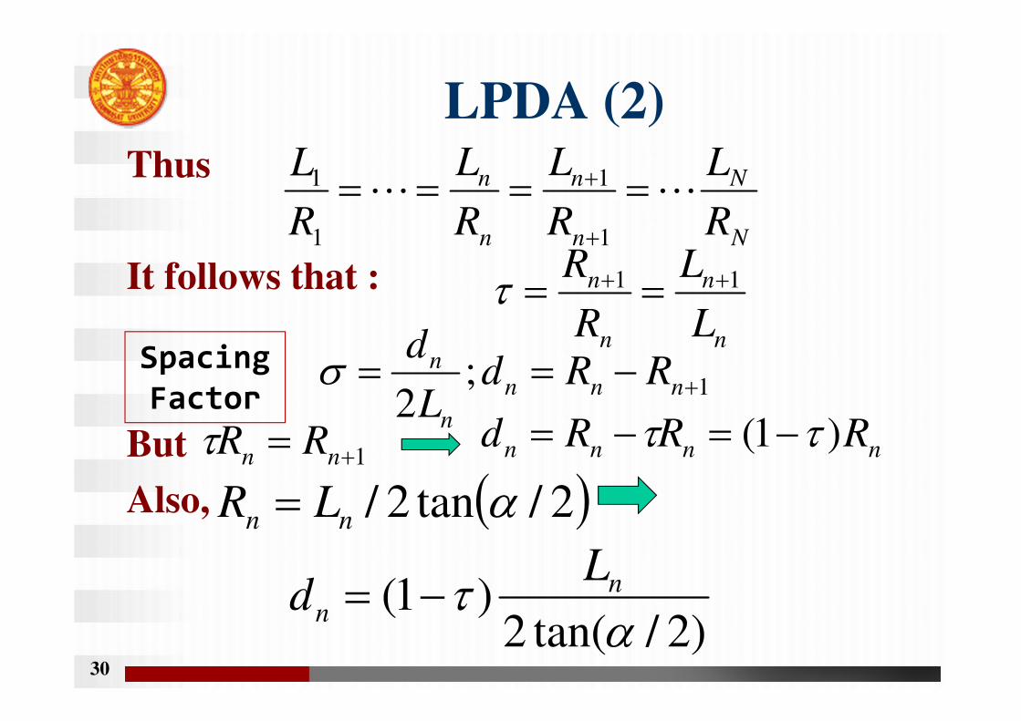
LPDA (2)Thus
It follows that :
But
Also,
30
N
N
n
n
n
n
R
L
R
L
R
L
R
LLL ====
+
+
1
1
1
1
n
n
n
n
L
L
R
R 11 ++ ==τ
Spacing
Factor 1;2
+−== nnn
n
n RRdL
dσ
1+= nn RRτ nnnn RRRd )1( ττ −=−=
( )2/tan2/ αnn LR =
)2/tan(2)1(
ατ n
n
Ld −=
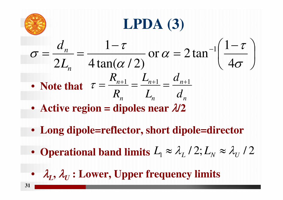
LPDA (3)
• Note that
• Active region = dipoles near λλλλ/2
• Long dipole=reflector, short dipole=director
• Operational band limits
• λλλλL, λλλλU : Lower, Upper frequency limits31
−=
−== −
στ
αατ
σ4
1tan2or
)2/tan(4
1
2
1
n
n
L
d
n
n
n
n
n
n
d
d
L
L
R
R 111 +++ ===τ
2/;2/1 UNL LL λλ ≈≈
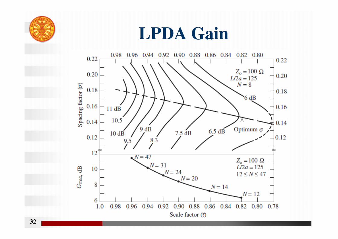
LPDA Gain
32
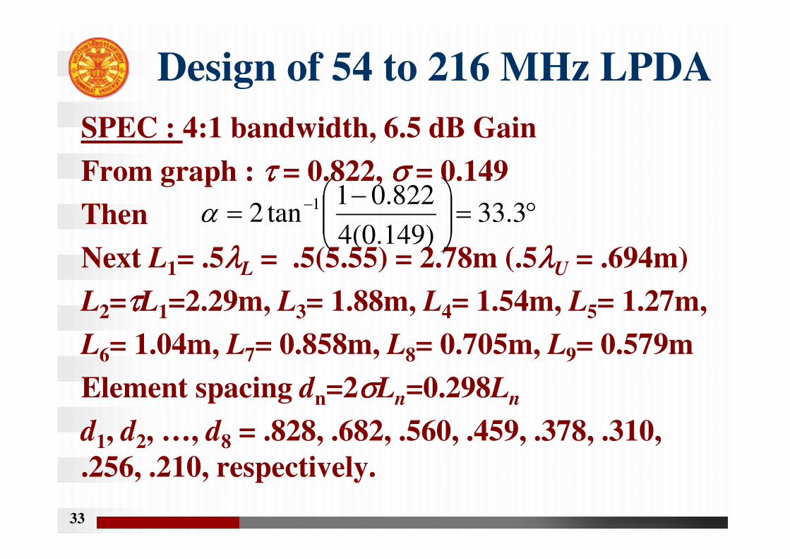
Design of 54 to 216 MHz LPDA
SPEC : 4:1 bandwidth, 6.5 dB Gain
From graph : ττττ = 0.822, σ σ σ σ = 0.149
Then
Next L1= .5λλλλL = .5(5.55) = 2.78m (.5λλλλU = .694m)
L2=ττττL1=2.29m, L3= 1.88m, L4= 1.54m, L5= 1.27m,
L6= 1.04m, L7= 0.858m, L8= 0.705m, L9= 0.579m
Element spacing dn=2σσσσLn=0.298Ln
d1, d2, …, d8 = .828, .682, .560, .459, .378, .310,
.256, .210, respectively.
33
°=
−= − 3.33
)149.0(4
822.01tan2 1α
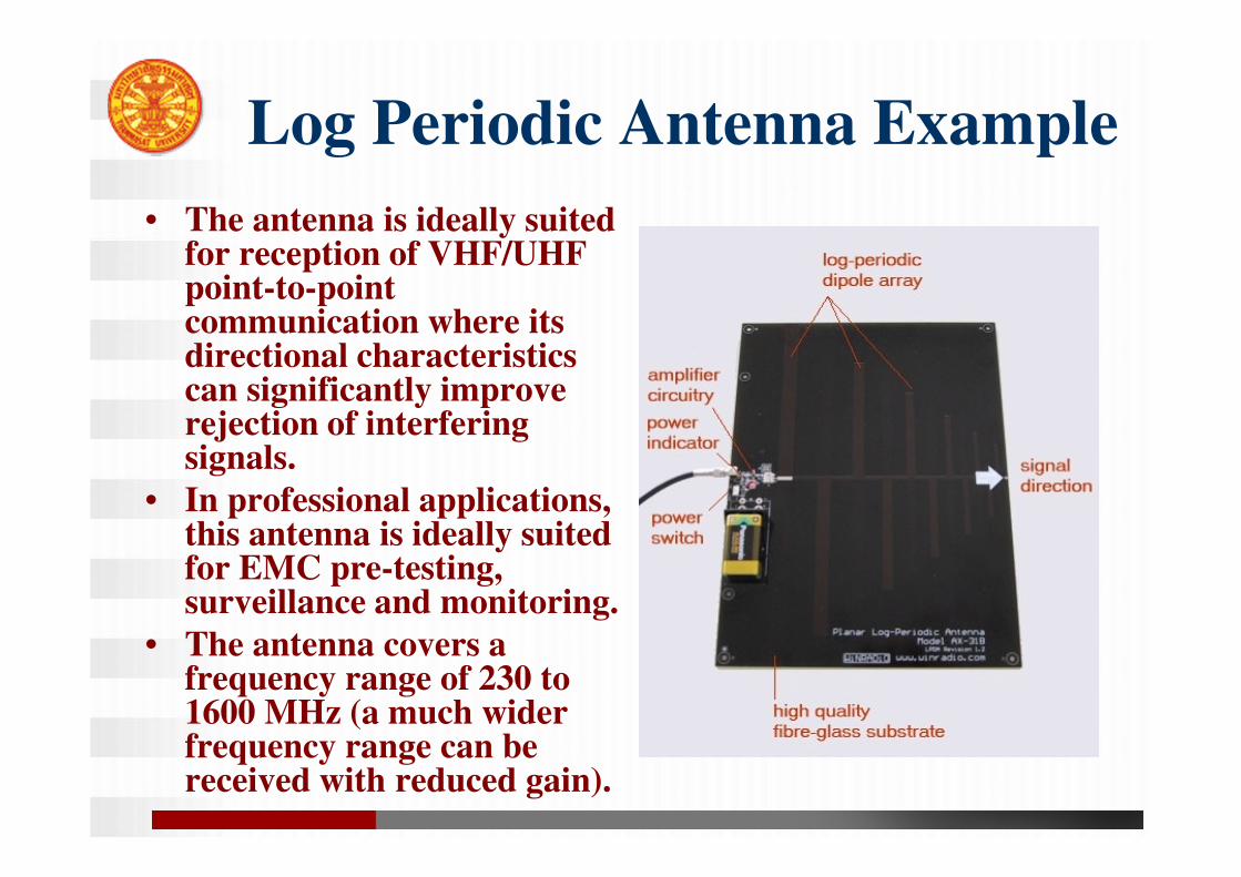
Log Periodic Antenna Example
• The antenna is ideally suited for reception of VHF/UHF point-to-point communication where its directional characteristics can significantly improve rejection of interfering signals.
• In professional applications, this antenna is ideally suited for EMC pre-testing, surveillance and monitoring.
• The antenna covers a frequency range of 230 to 1600 MHz (a much wider frequency range can be received with reduced gain).
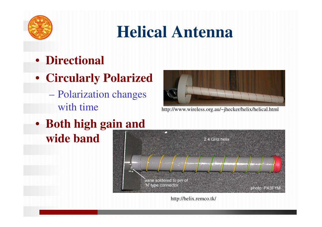
Helical Antenna
• Directional
• Circularly Polarized
– Polarization changes
with time
• Both high gain and
wide band
http://helix.remco.tk/
http://www.wireless.org.au/~jhecker/helix/helical.html
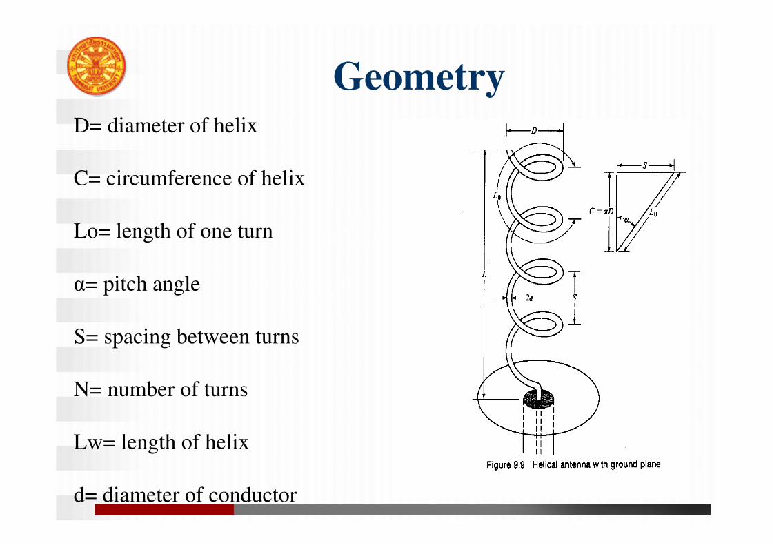
GeometryD= diameter of helix
C= circumference of helix
Lo= length of one turn
α= pitch angle
S= spacing between turns
N= number of turns
Lw= length of helix
d= diameter of conductor
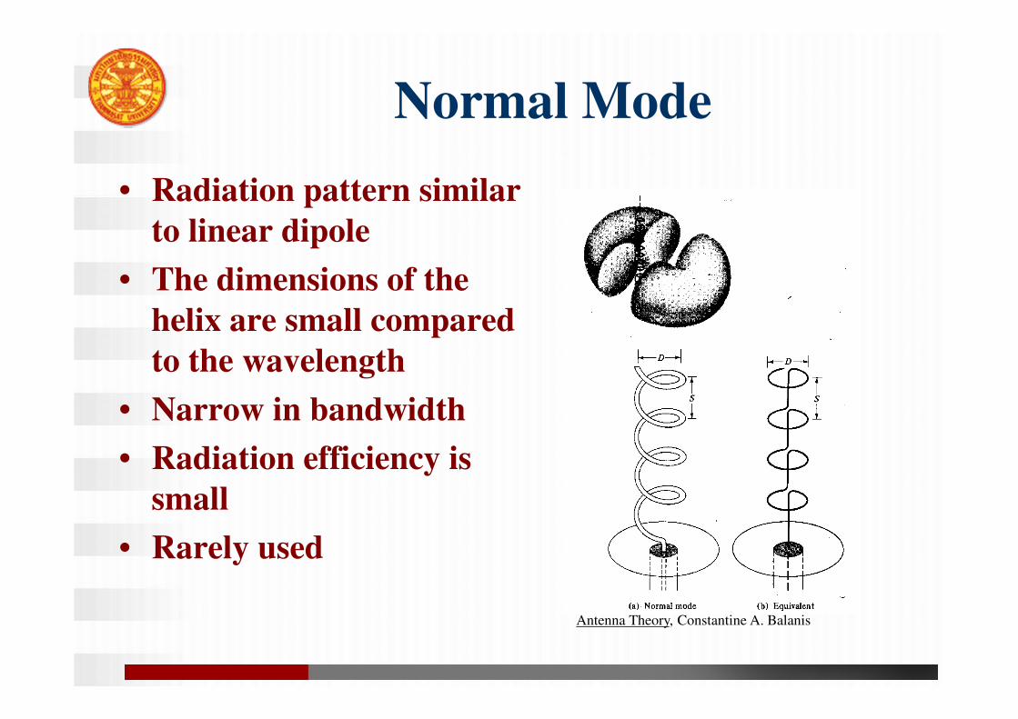
Normal Mode
• Radiation pattern similar
to linear dipole
• The dimensions of the
helix are small compared
to the wavelength
• Narrow in bandwidth
• Radiation efficiency is
small
• Rarely used
Antenna Theory, Constantine A. Balanis
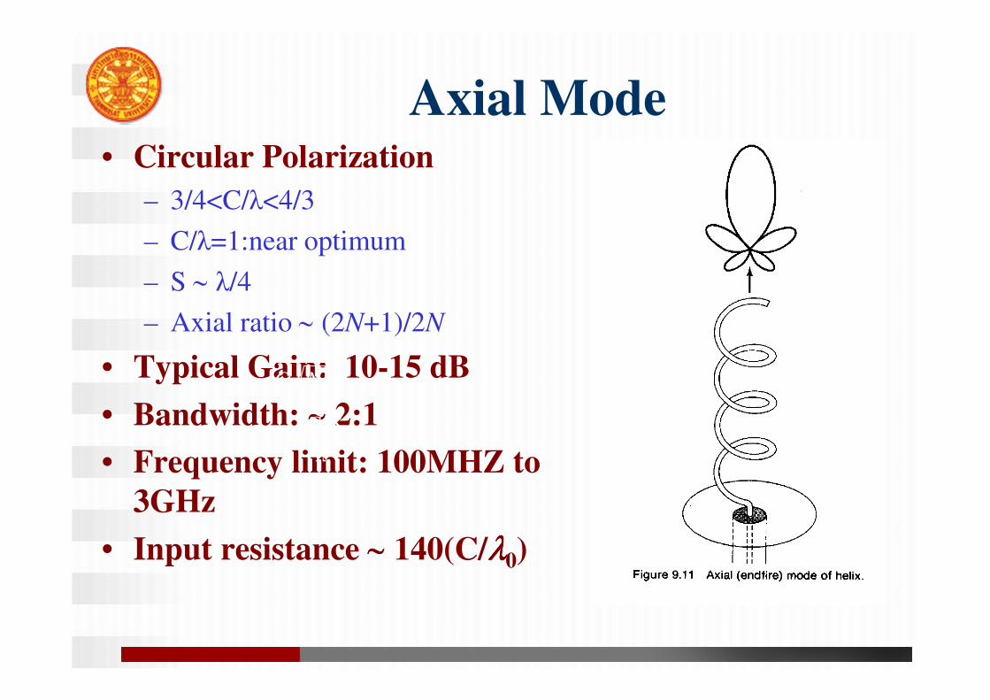
Axial Mode• Circular Polarization
– 3/4<C/λ<4/3
– C/λ=1:near optimum
– S ∼ λ/4
– Axial ratio ∼ (2N+1)/2N
• Typical Gain: 10-15 dB
• Bandwidth: ∼∼∼∼ 2:1
• Frequency limit: 100MHZ to
3GHz
• Input resistance ∼∼∼∼ 140(C/λλλλ0)
NSC
23
52λ
3
2
15λ
SCN
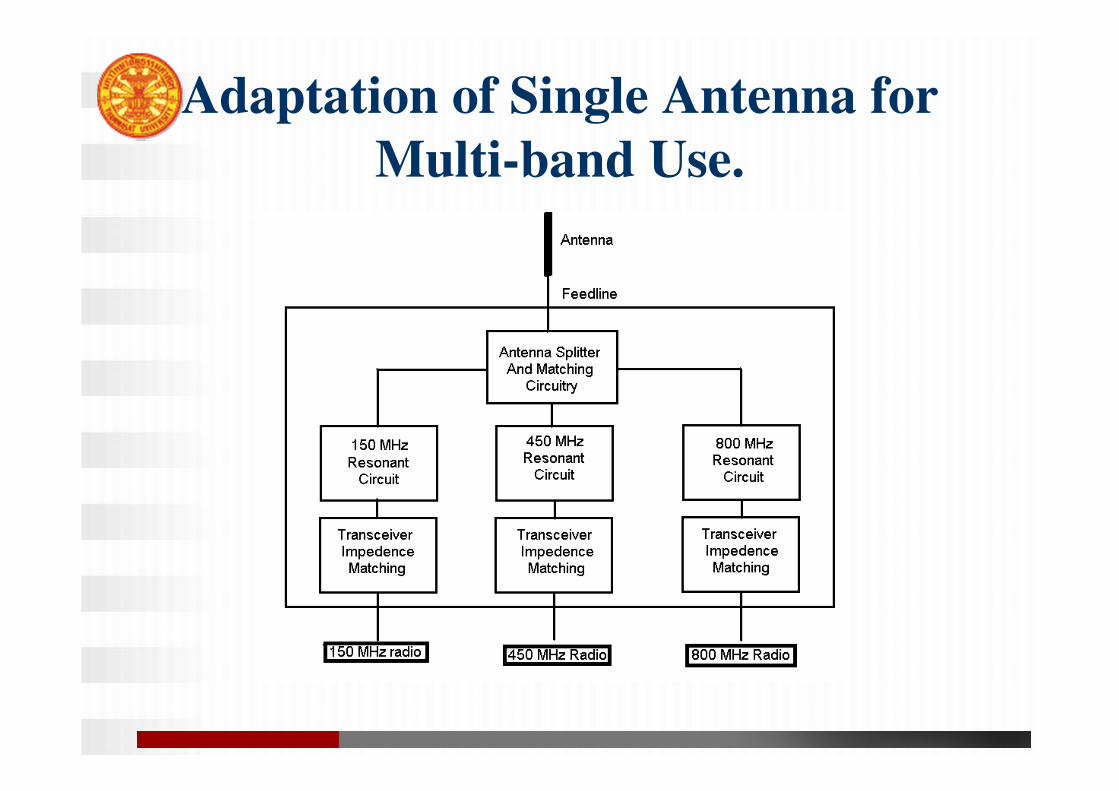
Adaptation of Single Antenna for
Multi-band Use.
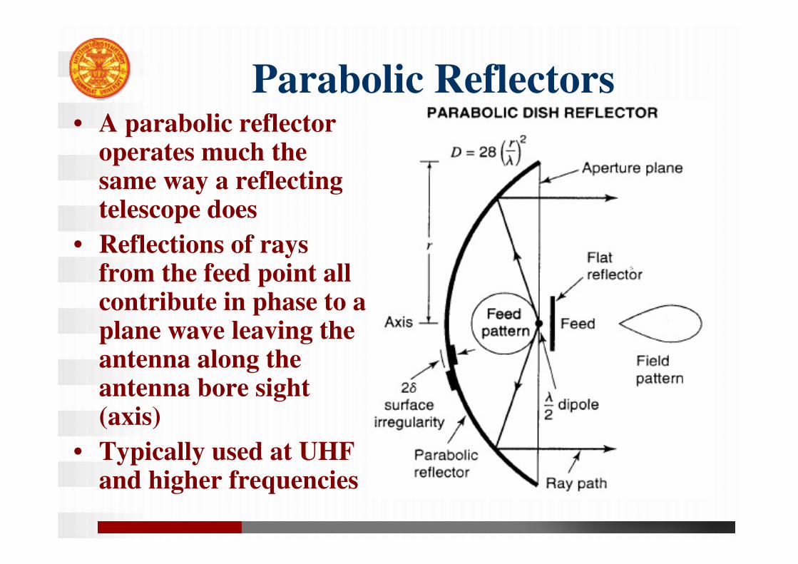
Parabolic Reflectors• A parabolic reflector
operates much the same way a reflecting telescope does
• Reflections of rays from the feed point all contribute in phase to a plane wave leaving the antenna along the antenna bore sight (axis)
• Typically used at UHF and higher frequencies
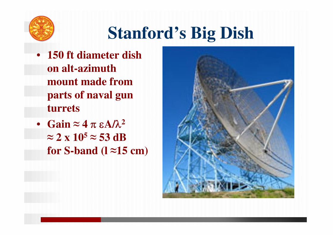
Stanford’s Big Dish
• 150 ft diameter dish
on alt-azimuth
mount made from
parts of naval gun
turrets
• Gain ≈ 4 ππππ εεεεA/λλλλ2
≈ 2 x 10⁵ ≈ 53 dB
for S-band (l ≈15 cm)
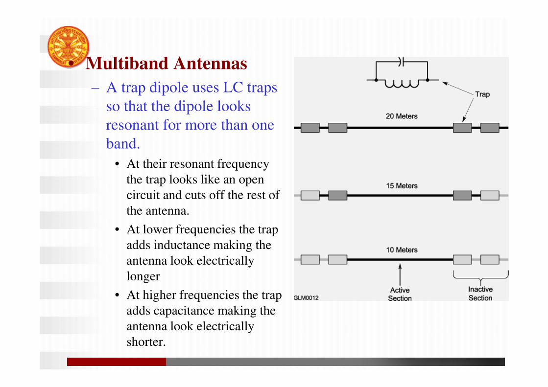
• Multiband Antennas
– A trap dipole uses LC traps
so that the dipole looks
resonant for more than one
band.
• At their resonant frequency
the trap looks like an open
circuit and cuts off the rest of
the antenna.
• At lower frequencies the trap
adds inductance making the
antenna look electrically
longer
• At higher frequencies the trap
adds capacitance making the
antenna look electrically
shorter.
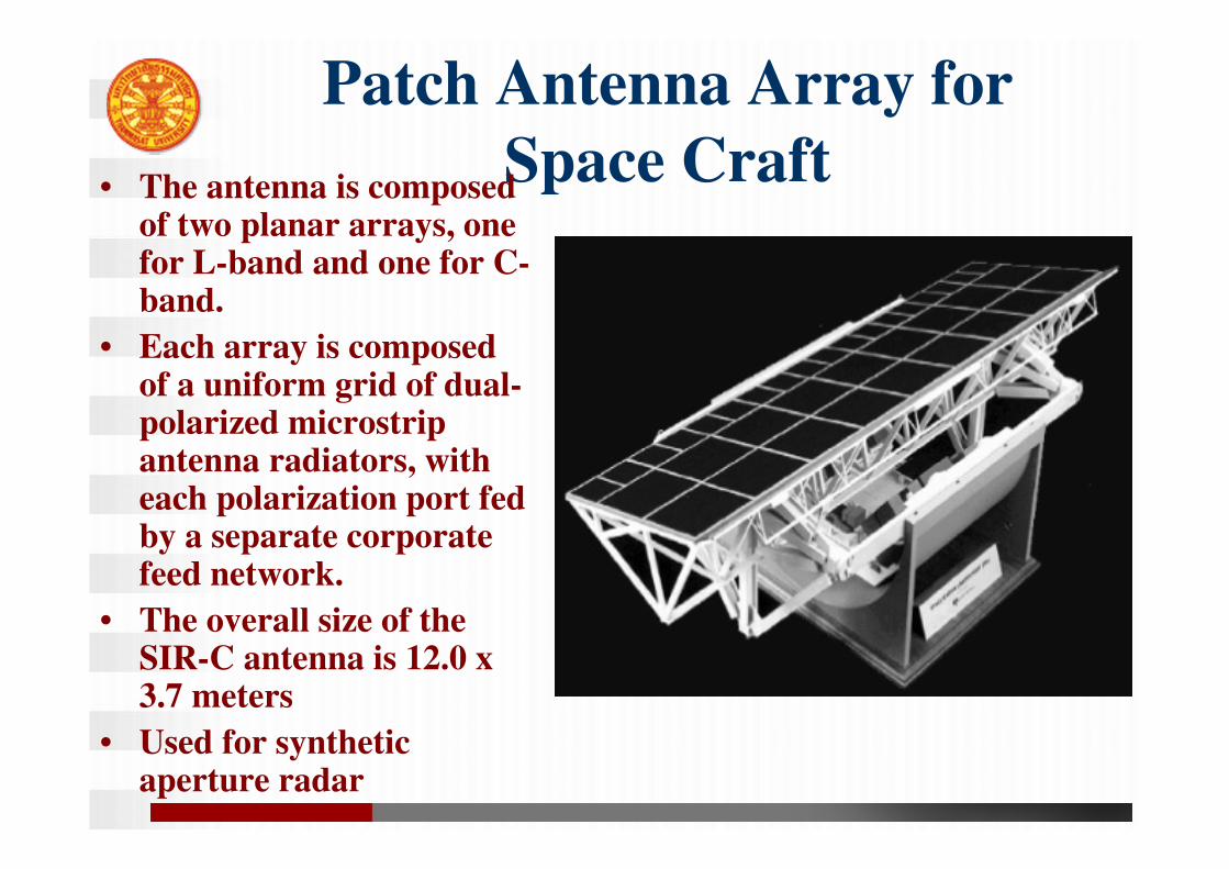
Patch Antenna Array for
Space Craft• The antenna is composed
of two planar arrays, one for L-band and one for C-band.
• Each array is composed of a uniform grid of dual-polarized microstrip antenna radiators, with each polarization port fed by a separate corporate feed network.
• The overall size of the SIR-C antenna is 12.0 x 3.7 meters
• Used for synthetic aperture radar
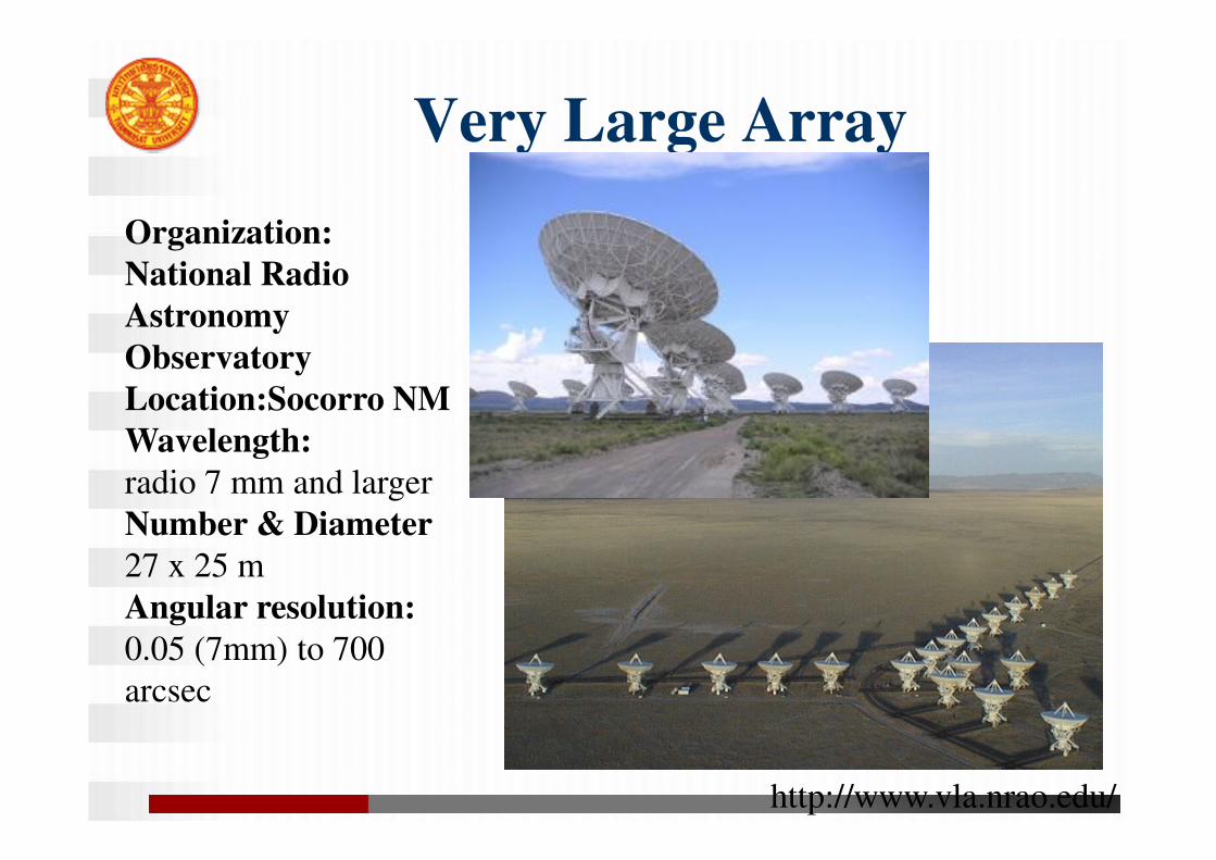
Very Large Array
http://www.vla.nrao.edu/
Organization:
National Radio
Astronomy
Observatory
Location:Socorro NM
Wavelength:
radio 7 mm and larger
Number & Diameter
27 x 25 m
Angular resolution:
0.05 (7mm) to 700
arcsec
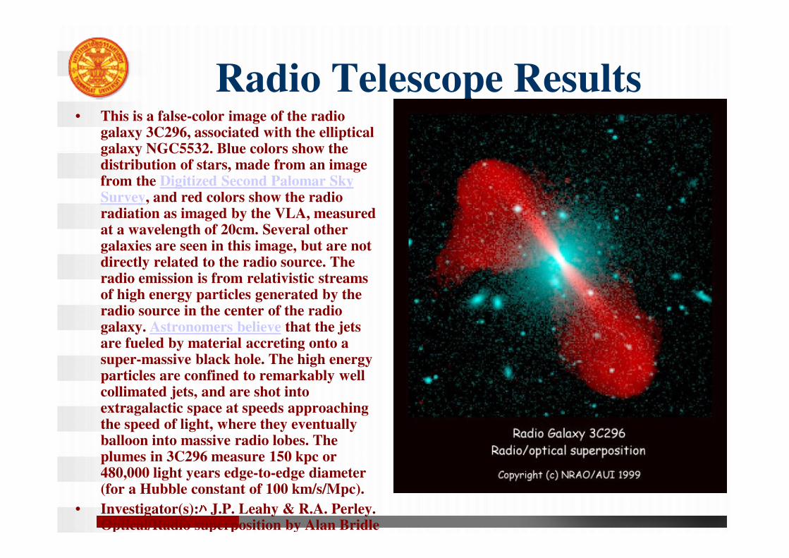
Radio Telescope Results• This is a false-color image of the radio
galaxy 3C296, associated with the elliptical galaxy NGC5532. Blue colors show the distribution of stars, made from an image from the Digitized Second Palomar Sky Survey, and red colors show the radio radiation as imaged by the VLA, measured at a wavelength of 20cm. Several other galaxies are seen in this image, but are not directly related to the radio source. The radio emission is from relativistic streams of high energy particles generated by the radio source in the center of the radio galaxy. Astronomers believe that the jets are fueled by material accreting onto a super-massive black hole. The high energy particles are confined to remarkably well collimated jets, and are shot into extragalactic space at speeds approaching the speed of light, where they eventually balloon into massive radio lobes. The plumes in 3C296 measure 150 kpc or 480,000 light years edge-to-edge diameter (for a Hubble constant of 100 km/s/Mpc).
• Investigator(s):ハハハハ J.P. Leahy & R.A. Perley. Optical/Radio superposition by Alan Bridle
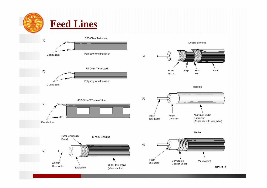
Feed Lines
• All feed lines have two conductors
• All feed lines have a characteristic
impedance (Z0).
• The characteristic impedance of parallel
feed lines (balanced feed lines) is
determined by the radius of the conductors
and the distance between them.
– TV type twin lead has an impedance of 300 Ω.
– Open wire or ladder line has impedances from 300
to 600 Ω.
• The characteristic impedance of coaxial
transmission lines is determined by the
diameter of the inner and outer conductors,
and their spacing.
– The insulating material between the inner and
outer conductors affects the feed line loss and
velocity factor (how fast a wave travels down the
cable).
– 50 Ω and 75 Ω cables are the most common.
Forward and Reflected Power
• A feed line delivers all the power to the antenna when the antenna’s feed point impedance and the feed line’s characteristic impedance are the same.
• A reflection occurs when the impedances don’t match. Forward power is power traveling toward the antenna and reflected power is power reflected back due to the impedance mismatch.
• The forward and reflected power create standing waves on the transmission line.
• A standing wave ratio (SWR) of 1:1
represents a perfect match (no reflected
power). A higher SWR means more
reflected power.
• SWR is the ratio of the antenna impedance
to the feed line characteristic impedance,
and is always greater than 1.
– Example: What is the SWR in a 50 Ω transmission
line when connected to an antenna with a feed
point impedance of 25 Ω?
• SWR = 50/25 = 2:1
– Example: What is the SWR in a 50 Ω transmission line when connected to an antenna with a feed point impedance of 250 Ω?
• SWR = 250/50 = 5:1
• A high SWR can damage a transmitter because of the reflected power returning the transistors (or tubes) in the final power amplifier.
• Matching the antenna to the feed line will maximize the power delivered from the transmitter to the antenna.
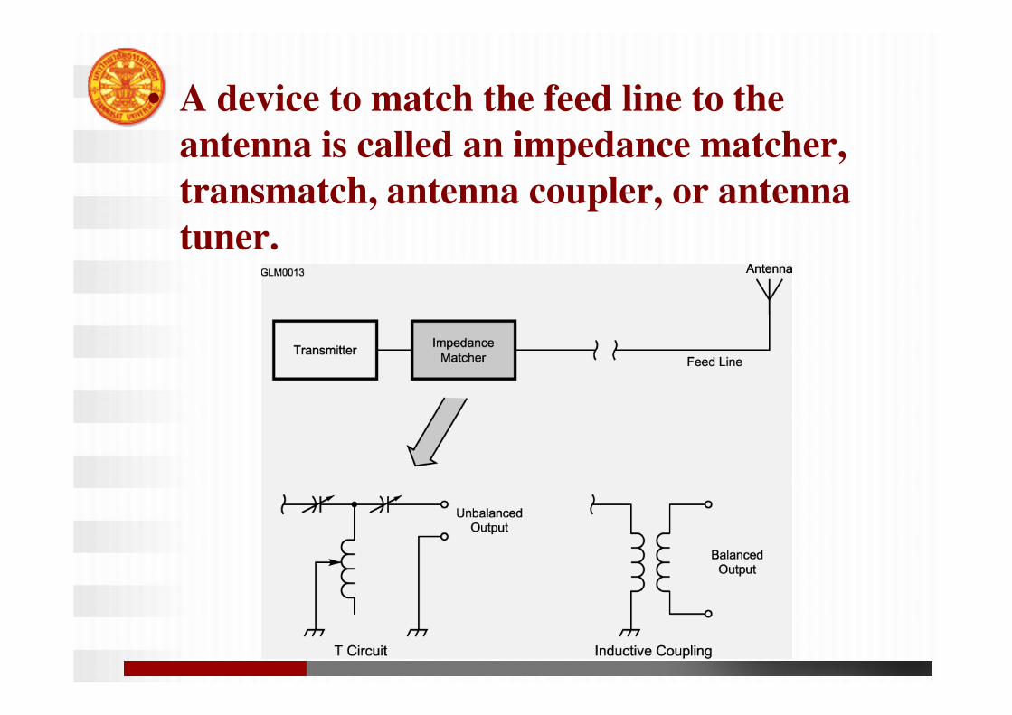
• A device to match the feed line to the
antenna is called an impedance matcher,
transmatch, antenna coupler, or antenna
tuner.
• A section of transmission line connected in
parallel, called a stub, can be used to match
impedances.
• Impedance matching does not change the
SWR in the feed line from the matching
device to the antenna. Only the SWR
between the transmitter and the impedance
matching device will be low.
Feed Line Loss
• All feed lines will dissipate some energy as
heat. This loss effects both receive and
transmit.
• Air insulated transmission lines tend to have
the lowest loss.
• Loss is measured in dB/100 feet.
• Loss increases with frequency for all
transmission lines.
– Example: RG-8 has a loss of 1.08 dB/100 ft at 30
MHz and 2.53 dB/100 ft at 150 MHz.