
oil ϑ 3/3 directional servo-valve with RE 29583-XH-104-B2 ...
16
1/14 3/3 directional servo-valve with mechanical position feedback Type 4WS2EM 10...XH...-104 Size 10 Component series 5X Maximum operating pressure 315 bar Maximum flow 180 l/min RE 29583-XH-104-B2/12.11 Replaces: 07.11 H5893 ATEX units For explosive areas Part II Data sheet What you need to know about these operating instructions These operating instructions apply to the explosion-proof version of Rexroth valves and consist of the following three parts: Part I General information 07010-X-B1 Part II Data sheet 29583-XH-104-B2 Part III Product-specific instructions 29583-XH-104-B3 You can find further information on the correct handling of Rexroth hydraulic products in our publication "General product information on hydraulic products" 07008. Operating instructions 29583-XH-104-B0 Information on explosion protection: Range of application in accordance with the Explosion Protection Directive 94/9/EC II 1G: Type of protection Ex ia IIC T4 Ga according to EN 60079-0:2009 / EN 60079-11:2007
Transcript of oil ϑ 3/3 directional servo-valve with RE 29583-XH-104-B2 ...

InhaltTable of contents 2Features 2Ordering code and scope of delivery 3Symbol 3Function, section 4Technical data 5Technical data 6Information on explosion protection 6External control electronics 6Mating connector 7Electrical connection 7Characteristic curves (measured with HLP32, ϑoil = 40 °C ± 5 °C) 8Characteristic curves (measured with HLP 32, ϑoil = 40 °C ± 5 °C) 9Characteristic curves (measured with HLP 32, ϑoil = 40 °C ± 5 °C) 10Characteristic curves (measured with HLP 32, ϑoil = 40 °C ± 5 °C) 11Unit dimensions (dimensions in mm) 12Flushing plate with porting pattern according to ISO 4401-05-05-0-05 (dimensions in mm) 13Notes 14Notes 15Notes 16
1/14
3/3 directional servo-valve with mechanical position feedback
Type 4WS2EM 10...XH...-104
Size 10Component series 5XMaximum operating pressure 315 barMaximum flow 180 l/min
RE 29583-XH-104-B2/12.11Replaces: 07.11
H5893
ATEX units For explosive areas Part II Data sheet
What you need to know about these operating instructions
These operating instructions apply to the explosion-proof version of Rexroth valves and consist of the following three parts:Part I General information 07010-X-B1 Part II Data sheet 29583-XH-104-B2 Part III Product-specific instructions 29583-XH-104-B3You can find further information on the correct handling of Rexroth hydraulic products in our publication "General product information on hydraulic products" 07008.
Operating instructions 29583-XH-104-B0
Information on explosion protection:Range of application in accordance with the Explosion Protection Directive 94/9/ECII 1G: Type of protection Ex ia IIC T4 Ga according to
EN 60079-0:2009 / EN 60079-11:2007
2/14 Bosch Rexroth AG Hydraulics 4WS2EM 10...XH...-104 RE 29583-XH-104-B2
Table of contents
Features
– Directional servo-valve for proper use in explosive areas of zone 0
– Valve to control position, force, pressure or velocity – 2-stage servo valve with mechanical feedback– 1st stage as nozzle flapper plate amplifier– For subplate mounting, porting pattern according to
ISO 4401-05-05-0-05 with ports X and Y suplates available in FE/ZN version (see page 12)
– Dry control motor, no contamination of the solenoid gaps by the hydraulic fluid
– Wear-free spool feedback element– Control:
External control electronics in modular design, additional safety barrier (separate order), see page 6
– Valve is adjusted and tested– Internal/external pilot oil supply and return can be ordered
individually– Spool with flow force compensation– Control sleeve centrically fixed, thus low susceptibility to
temperature and pressure– Pressure chambers at the control sleeve with gap seal,
therefore no wear of the seal ring– Filter for 1st stage freely accessible from the outside
Content PageFeatures 2Ordering code and scope of delivery 3Symbol 3Function, section 4Technical data 5 and 6Information on explosion protection 6External control electronics 6Mating connector 7Electrical connection 7Characteristic curves 8 to 11Unit dimensions 12Flushing plate 13
Hydraulics Bosch Rexroth AGRE 29583-XH-104-B2 4WS2EM 10...XH...-104 3/14
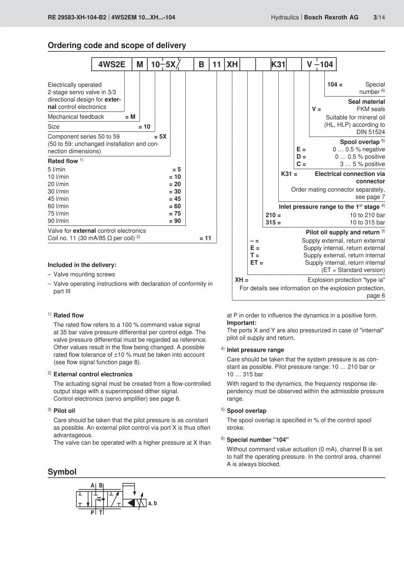
Ordering code and scope of delivery
Electrically operated 2-stage servo valve in 3/3 directional design for exter-nal control electronicsMechanical feedback = MSize = 10Component series 50 to 59 = 5X (50 to 59: unchanged installation and con-nection dimensions)Rated flow 1)
5 l/min = 5 10 l/min = 10 20 l/min = 20 30 l/min = 30 45 l/min = 45 60 l/min = 60 75 l/min = 75 90 l/min = 90Valve for external control electronics Coil no. 11 (30 mA/85 Ω per coil) 2) = 11
Symbol
Included in the delivery:– Valve mounting screws– Valve operating instructions with declaration of conformity in
part III
1) Rated flow The rated flow refers to a 100 % command value signal
at 35 bar valve pressure differential per control edge. The valve pressure differential must be regarded as reference. Other values result in the flow being changed. A possible rated flow tolerance of ±10 % must be taken into account (see flow signal function page 8).
2) External control electronics The actuating signal must be created from a flow-controlled
output stage with a superimposed dither signal. Control electronics (servo amplifier) see page 6.
3) Pilot oil Care should be taken that the pilot pressure is as constant
as possible. An external pilot control via port X is thus often advantageous. The valve can be operated with a higher pressure at X than
at P in order to influence the dynamics in a positive form. Important: The ports X and Y are also pressurized in case of "internal" pilot oil supply and return.
4) Inlet pressure range Care should be taken that the system pressure is as con-
stant as possible. Pilot pressure range: 10 … 210 bar or 10 … 315 bar
With regard to the dynamics, the frequency response de-pendency must be observed within the admissible pressure range.
5) Spool overlap The spool overlap is specified in % of the control spool
stroke.6) Special number "104" Without command value actuation (0 mA), channel B is set
to half the operating pressure. In the control area, channel A is always blocked.
4WS2E M 10 5X B 11 XH K31 V 104
104 = Special number 6)
Seal material V = FKM seals
Suitable for mineral oil (HL, HLP) according to
DIN 51524 Spool overlap 5) E = 0 … 0.5 % negative D = 0 … 0.5 % positive C = 3 … 5 % positive
K31 = Electrical connection via connector
Order mating connector separately, see page 7
Inlet pressure range to the 1st stage 4)
210 = 10 to 210 bar 315 = 10 to 315 bar
Pilot oil supply and return 3)
– = Supply external, return external E = Supply internal, return external T = Supply external, return internal ET = Supply internal, return internal
(ET = Standard version)XH = Explosion protection "type ia"
For details see information on the explosion protection, page 6
4/14 Bosch Rexroth AG Hydraulics 4WS2EM 10...XH...-104 RE 29583-XH-104-B2
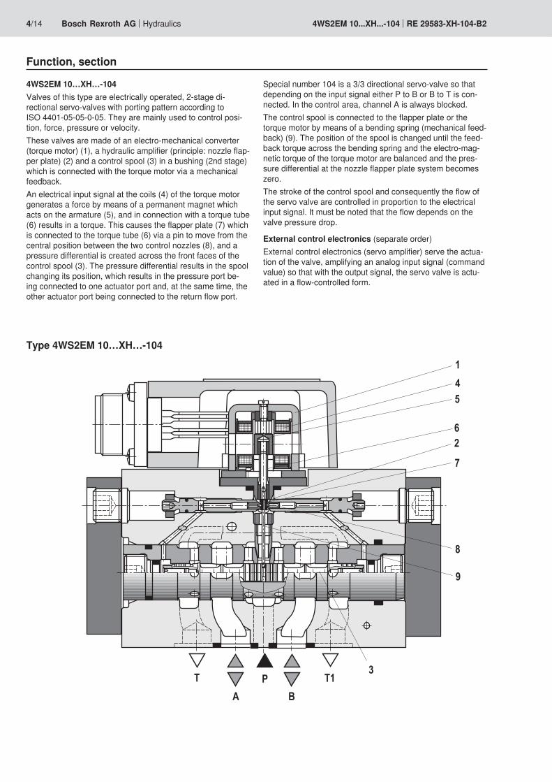
Function, section
4WS2EM 10…XH…-104Valves of this type are electrically operated, 2-stage di-rectional servo-valves with porting pattern according to ISO 4401-05-05-0-05. They are mainly used to control posi-tion, force, pressure or velocity.These valves are made of an electro-mechanical converter (torque motor) (1), a hydraulic amplifier (principle: nozzle flap-per plate) (2) and a control spool (3) in a bushing (2nd stage) which is connected with the torque motor via a mechanical feedback.An electrical input signal at the coils (4) of the torque motor generates a force by means of a permanent magnet which acts on the armature (5), and in connection with a torque tube (6) results in a torque. This causes the flapper plate (7) which is connected to the torque tube (6) via a pin to move from the central position between the two control nozzles (8), and a pressure differential is created across the front faces of the control spool (3). The pressure differential results in the spool changing its position, which results in the pressure port be-ing connected to one actuator port and, at the same time, the other actuator port being connected to the return flow port.
Special number 104 is a 3/3 directional servo-valve so that depending on the input signal either P to B or B to T is con-nected. In the control area, channel A is always blocked.The control spool is connected to the flapper plate or the torque motor by means of a bending spring (mechanical feed-back) (9). The position of the spool is changed until the feed-back torque across the bending spring and the electro-mag-netic torque of the torque motor are balanced and the pres-sure differential at the nozzle flapper plate system becomes zero.The stroke of the control spool and consequently the flow of the servo valve are controlled in proportion to the electrical input signal. It must be noted that the flow depends on the valve pressure drop.
External control electronics (separate order)External control electronics (servo amplifier) serve the actua-tion of the valve, amplifying an analog input signal (command value) so that with the output signal, the servo valve is actu-ated in a flow-controlled form.
Type 4WS2EM 10…XH…-104
Hydraulics Bosch Rexroth AGRE 29583-XH-104-B2 4WS2EM 10...XH...-104 5/14
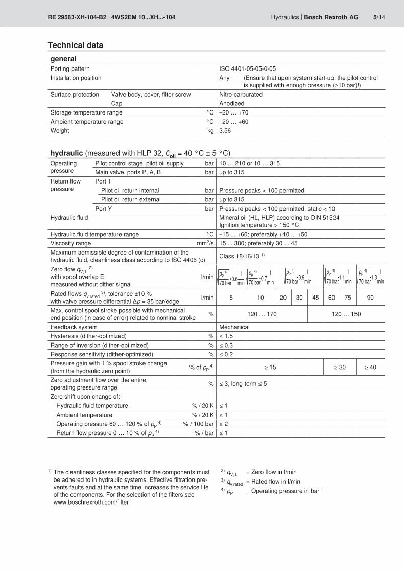
Technical data
1) The cleanliness classes specified for the components must be adhered to in hydraulic systems. Effective filtration pre-vents faults and at the same time increases the service life of the components. For the selection of the filters see www.boschrexroth.com/filter
2) qV, L = Zero flow in l/min3) qv rated = Rated flow in l/min4) pP = Operating pressure in bar
generalPorting pattern ISO 4401-05-05-0-05Installation position Any (Ensure that upon system start-up, the pilot control
is supplied with enough pressure (≥10 bar)!)Surface protection Valve body, cover, filter screw Nitro-carburated
Cap AnodizedStorage temperature range °C –20 … +70Ambient temperature range °C –20 … +60 Weight kg 3.56
hydraulic (measured with HLP 32, ϑoil = 40 °C ± 5 °C)Operating pressure
Pilot control stage, pilot oil supply bar 10 … 210 or 10 … 315Main valve, ports P, A, B bar up to 315
Return flow pressure
Port TPilot oil return internal bar Pressure peaks < 100 permittedPilot oil return external bar up to 315
Port Y bar Pressure peaks < 100 permitted, static < 10 Hydraulic fluid Mineral oil (HL, HLP) according to DIN 51524
Ignition temperature > 150 °CHydraulic fluid temperature range °C –15 ... +60; preferably +40 ... +50Viscosity range mm2/s 15 ... 380; preferably 30 ... 45Maximum admissible degree of contamination of the hydraulic fluid, cleanliness class according to ISO 4406 (c) Class 18/16/13 1)
Zero flow qV, L 2) with spool overlap E measured without dither signal
l/min pP 4) l70 bar min•0.6
pP 4) l70 bar min•0.7
pP 4) l70 bar min•0.9
pP 4) l70 bar min•1.1
pP 4) l70 bar min•1.3
Rated flows qv rated 3), tolerance ±10 % with valve pressure differential ∆p = 35 bar/edge l/min 5 10 20 30 45 60 75 90
Max. control spool stroke possible with mechanical end position (in case of error) related to nominal stroke % 120 … 170 120 … 150
Feedback system MechanicalHysteresis (dither-optimized) % ≤ 1.5Range of inversion (dither-optimized) % ≤ 0.3Response sensitivity (dither-optimized) % ≤ 0.2Pressure gain with 1 % spool stroke change (from the hydraulic zero point) % of pP
4) ≥ 15 ≥ 30 ≥ 40
Zero adjustment flow over the entire operating pressure range % ≤ 3, long-term ≤ 5
Zero shift upon change of:Hydraulic fluid temperature % / 20 K ≤ 1Ambient temperature % / 20 K ≤ 1Operating pressure 80 … 120 % of pP
4) % / 100 bar ≤ 2Return flow pressure 0 … 10 % of pP
4) % / bar ≤ 1
6/14 Bosch Rexroth AG Hydraulics 4WS2EM 10...XH...-104 RE 29583-XH-104-B2
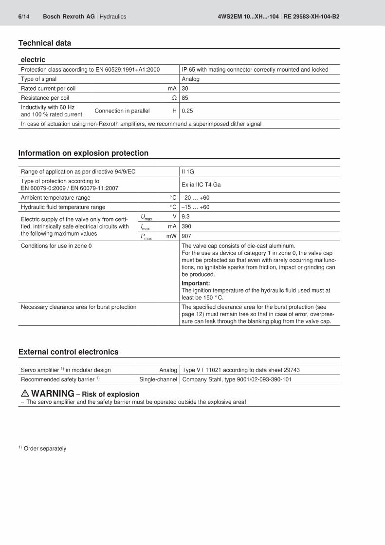
electricProtection class according to EN 60529:1991+A1:2000 IP 65 with mating connector correctly mounted and lockedType of signal AnalogRated current per coil mA 30Resistance per coil Ω 85Inductivity with 60 Hz and 100 % rated current Connection in parallel H 0.25
In case of actuation using non-Rexroth amplifiers, we recommend a superimposed dither signal
Technical data
Range of application as per directive 94/9/EC II 1GType of protection according to EN 60079-0:2009 / EN 60079-11:2007 Ex ia IIC T4 Ga
Ambient temperature range °C –20 … +60Hydraulic fluid temperature range °C –15 … +60
Electric supply of the valve only from certi-fied, intrinsically safe electrical circuits with the following maximum values
Umax V 9.3Imax mA 390Pmax mW 907
Conditions for use in zone 0 The valve cap consists of die-cast aluminum. For the use as device of category 1 in zone 0, the valve cap must be protected so that even with rarely occurring malfunc-tions, no ignitable sparks from friction, impact or grinding can be produced. Important: The ignition temperature of the hydraulic fluid used must at least be 150 °C.
Necessary clearance area for burst protection The specified clearance area for the burst protection (see page 12) must remain free so that in case of error, overpres-sure can leak through the blanking plug from the valve cap.
Servo amplifier 1) in modular design Analog Type VT 11021 according to data sheet 29743Recommended safety barrier 1) Single-channel Company Stahl, type 9001/02-093-390-101
WARNING – Risk of explosion– The servo amplifier and the safety barrier must be operated outside the explosive area!
Information on explosion protection
External control electronics
1) Order separately

Hydraulics Bosch Rexroth AGRE 29583-XH-104-B2 4WS2EM 10...XH...-104 7/14
Electrical connection
Mating connector
Mating connector according to EN 175201-804Metal versionSeparate order under the Material no. R900223890
The coils may only be connected in parallel. The electrical control with plus (+) at A and B and minus (–) at C and D results in the flow direction B → T. Reverse electrical control results in the flow direction P → B.Pins E, F and PE at the connector are not connected.
ImportantFor intrinsically safe electric circuits, only cables and lines ap-proved of for that purpose may be used.
Servo amplifier Safety barrier Valve: Coil A Coil B
PA PA
Non-explosive area Explosive area
Connection: Solder contacts with connection cross-section for litz wires 0.5 … 1.5 mm2
8/14 Bosch Rexroth AG Hydraulics 4WS2EM 10...XH...-104 RE 29583-XH-104-B2
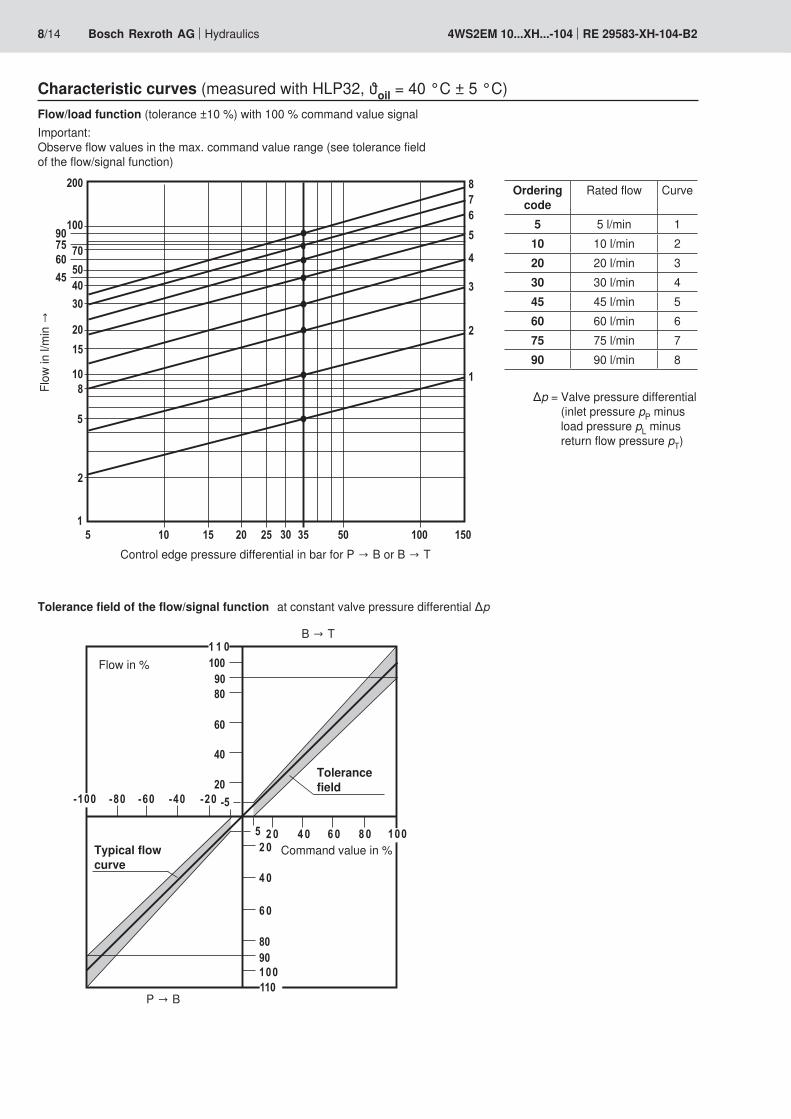
Characteristic curves (measured with HLP32, ϑoil = 40 °C ± 5 °C)
Control edge pressure differential in bar for P → B or B → T
Flow
in l/
min
→
∆p = Valve pressure differential (inlet pressure pP minus load pressure pL minus return flow pressure pT)
Flow/load function (tolerance ±10 %) with 100 % command value signalImportant: Observe flow values in the max. command value range (see tolerance field of the flow/signal function)
Tolerance field of the flow/signal function at constant valve pressure differential ∆p
B → T
P → B
Flow in %
Command value in %
Ordering code
Rated flow Curve
5 5 l/min 110 10 l/min 220 20 l/min 330 30 l/min 445 45 l/min 560 60 l/min 675 75 l/min 790 90 l/min 8
Typical flow curve
Tolerance field
Hydraulics Bosch Rexroth AGRE 29583-XH-104-B2 4WS2EM 10...XH...-104 9/14
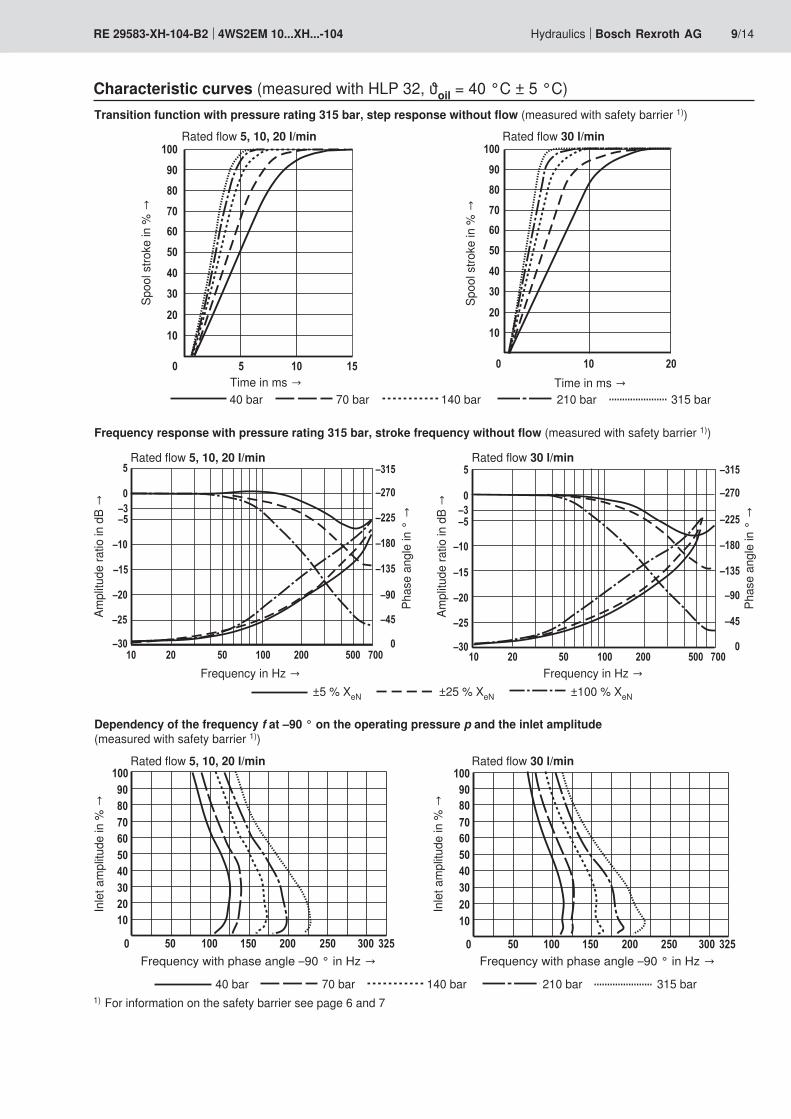
Characteristic curves (measured with HLP 32, ϑoil = 40 °C ± 5 °C)Transition function with pressure rating 315 bar, step response without flow (measured with safety barrier 1))
Frequency response with pressure rating 315 bar, stroke frequency without flow (measured with safety barrier 1))
Spoo
l stro
ke in
% →
Time in ms →
Dependency of the frequency f at –90 ° on the operating pressure p and the inlet amplitude (measured with safety barrier 1))
Inle
t am
plitu
de in
% →
Frequency with phase angle –90 ° in Hz →
Ampl
itude
ratio
in d
B →
Frequency in Hz →
Phas
e an
gle
in °
→
Rated flow 5, 10, 20 l/min Rated flow 30 l/min
40 bar 70 bar 140 bar 210 bar 315 bar
Spoo
l stro
ke in
% →
Time in ms →
Ampl
itude
ratio
in d
B →
Frequency in Hz →
Phas
e an
gle
in °
→
±5 % XeN ±25 % XeN ±100 % XeN
40 bar 70 bar 140 bar 210 bar 315 bar
Rated flow 5, 10, 20 l/min
Rated flow 5, 10, 20 l/minIn
let a
mpl
itude
in %
→
Frequency with phase angle –90 ° in Hz →
Rated flow 30 l/min
Rated flow 30 l/min
1) For information on the safety barrier see page 6 and 7
10/14 Bosch Rexroth AG Hydraulics 4WS2EM 10...XH...-104 RE 29583-XH-104-B2
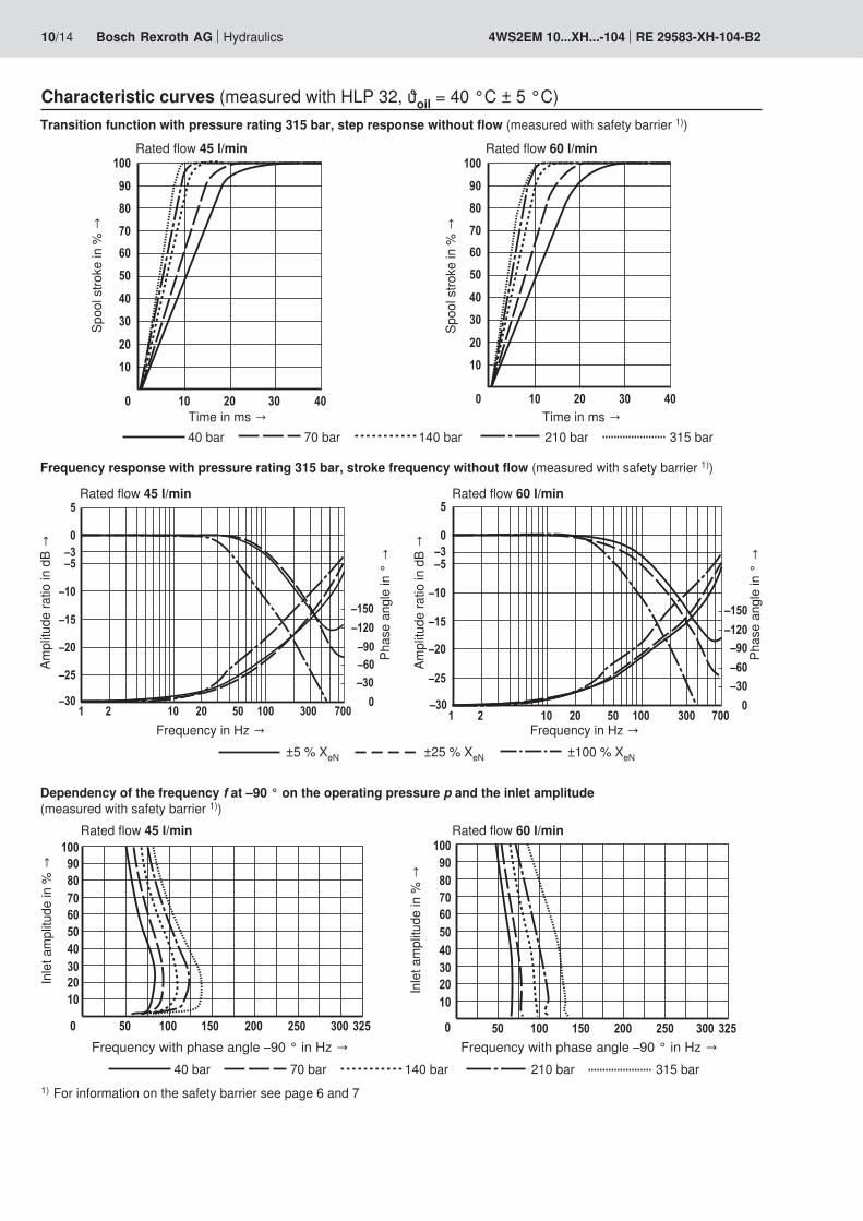
Transition function with pressure rating 315 bar, step response without flow (measured with safety barrier 1))
Frequency response with pressure rating 315 bar, stroke frequency without flow (measured with safety barrier 1))
Spoo
l stro
ke in
% →
Time in ms →
Dependency of the frequency f at –90 ° on the operating pressure p and the inlet amplitude (measured with safety barrier 1))
Inle
t am
plitu
de in
% →
Frequency with phase angle –90 ° in Hz →
Ampl
itude
ratio
in d
B →
Frequency in Hz →
Phas
e an
gle
in °
→
Rated flow 45 l/min Rated flow 60 l/min
40 bar 70 bar 140 bar 210 bar 315 barSp
ool s
troke
in %
→
Time in ms →Am
plitu
de ra
tio in
dB
→
Frequency in Hz →Ph
ase
angl
e in
° →
40 bar 70 bar 140 bar 210 bar 315 bar
Rated flow 45 l/min
Rated flow 45 l/min
Inle
t am
plitu
de in
% →
Frequency with phase angle –90 ° in Hz →
Rated flow 60 l/min
Rated flow 60 l/min
Characteristic curves (measured with HLP 32, ϑoil = 40 °C ± 5 °C)
1) For information on the safety barrier see page 6 and 7
±5 % XeN ±25 % XeN ±100 % XeN
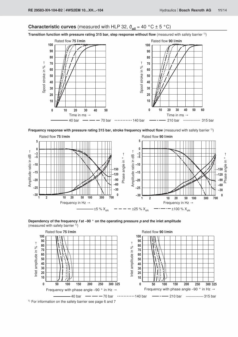
Hydraulics Bosch Rexroth AGRE 29583-XH-104-B2 4WS2EM 10...XH...-104 11/14
Transition function with pressure rating 315 bar, step response without flow (measured with safety barrier 1))
Frequency response with pressure rating 315 bar, stroke frequency without flow (measured with safety barrier 1))
Spoo
l stro
ke in
% →
Time in ms →
Dependency of the frequency f at –90 ° on the operating pressure p and the inlet amplitude (measured with safety barrier 1))
Inle
t am
plitu
de in
% →
Frequency with phase angle –90 ° in Hz →
Ampl
itude
ratio
in d
B →
Frequency in Hz →
Phas
e an
gle
in °
→
Rated flow 75 l/min Rated flow 90 l/min
40 bar 70 bar 140 bar 210 bar 315 bar
Spoo
l stro
ke in
% →
Time in ms →
40 bar 70 bar 140 bar 210 bar 315 bar
Rated flow 75 l/min
Rated flow 75 l/minIn
let a
mpl
itude
in %
→
Frequency with phase angle –90 ° in Hz →
Rated flow 90 l/min
Rated flow 90 l/min
Characteristic curves (measured with HLP 32, ϑoil = 40 °C ± 5 °C)
Ampl
itude
ratio
in d
B →
Frequency in Hz →
Phas
e an
gle
in °
→
±5 % XeN ±25 % XeN ±100 % XeN
1) For information on the safety barrier see page 6 and 7
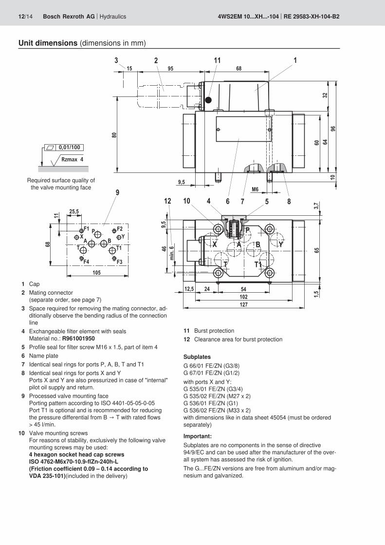
0,01/100
Rzmax 4
12/14 Bosch Rexroth AG Hydraulics 4WS2EM 10...XH...-104 RE 29583-XH-104-B2
Unit dimensions (dimensions in mm)
1 Cap2 Mating connector
(separate order, see page 7)3 Space required for removing the mating connector, ad-
ditionally observe the bending radius of the connection line
4 Exchangeable filter element with seals Material no.: R961001950
5 Profile seal for filter screw M16 x 1.5, part of item 46 Name plate7 Identical seal rings for ports P, A, B, T and T18 Identical seal rings for ports X and Y
Ports X and Y are also pressurized in case of "internal" pilot oil supply and return.
9 Processed valve mounting face Porting pattern according to ISO 4401-05-05-0-05 Port T1 is optional and is recommended for reducing the pressure differential from B → T with rated flows > 45 l/min.
10 Valve mounting screws For reasons of stability, exclusively the following valve mounting screws may be used: 4 hexagon socket head cap screws ISO 4762-M6x70-10.9-flZn-240h-L (Friction coefficient 0.09 – 0.14 according to VDA 235-101)(included in the delivery)
11 Burst protection12 Clearance area for burst protection
SubplatesG 66/01 FE/ZN (G3/8) G 67/01 FE/ZN (G1/2)with ports X and Y: G 535/01 FE/ZN (G3/4) G 535/02 FE/ZN (M27 x 2) G 536/01 FE/ZN (G1) G 536/02 FE/ZN (M33 x 2) with dimensions like in data sheet 45054 (must be ordered separately)
Important:Subplates are no components in the sense of directive 94/9/EC and can be used after the manufacturer of the over-all system has assessed the risk of ignition.The G...FE/ZN versions are free from aluminum and/or mag-nesium and galvanized.
Required surface quality of the valve mounting face
Hydraulics Bosch Rexroth AGRE 29583-XH-104-B2 4WS2EM 10...XH...-104 13/14
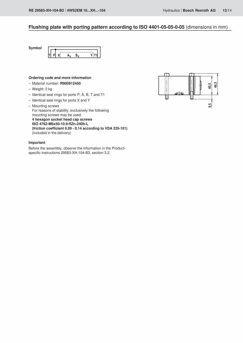
Flushing plate with porting pattern according to ISO 4401-05-05-0-05 (dimensions in mm)
Symbol
Ordering code and more information– Material number: R900912450– Weight: 2 kg– Identical seal rings for ports P, A, B, T and T1– Identical seal rings for ports X and Y– Mounting screws
For reasons of stability, exclusively the following mounting screws may be used: 4 hexagon socket head cap screws ISO 4762-M6x50-10.9-flZn-240h-L (friction coefficient 0.09 - 0.14 according to VDA 235-101) (included in the delivery)
ImportantBefore the assembly, observe the information in the Product-specific instructions 29583-XH-104-B3, section 3.2.

Bosch Rexroth AG HydraulicsZum Eisengießer 197816 Lohr am Main, Germany Phone +49 (0) 93 52 / 18-0 Fax +49 (0) 93 52 / 18-23 [email protected] www.boschrexroth.de
© This document, as well as the data, specifications and other informa-tion set forth in it, are the exclusive property of Bosch Rexroth AG. It may not be reproduced or given to third parties without its consent.The data specified above only serve to describe the product. No state-ments concerning a certain condition or suitability for a certain applica-tion can be derived from our information. The information given does not release the user from the obligation of own judgment and verification. It must be remembered that our products are subject to a natural process of wear and aging.
14/14 Bosch Rexroth AG Hydraulics 4WS2EM 10...XH...-104 RE 29583-XH-104-B2
Notes
Bosch Rexroth AG HydraulicsZum Eisengießer 197816 Lohr am Main, Germany Phone +49 (0) 93 52 / 18-0 Fax +49 (0) 93 52 / 18-23 [email protected] www.boschrexroth.de
© This document, as well as the data, specifications and other informa-tion set forth in it, are the exclusive property of Bosch Rexroth AG. It may not be reproduced or given to third parties without its consent.The data specified above only serve to describe the product. No state-ments concerning a certain condition or suitability for a certain applica-tion can be derived from our information. The information given does not release the user from the obligation of own judgment and verification. It must be remembered that our products are subject to a natural process of wear and aging.
Hydraulics Bosch Rexroth AGRE 29583-XH-104-B2 4WS2EM 10...XH...-104 15/14
Notes

Bosch Rexroth AG HydraulicsZum Eisengießer 197816 Lohr am Main, Germany Phone +49 (0) 93 52 / 18-0 Fax +49 (0) 93 52 / 18-23 [email protected] www.boschrexroth.de
© This document, as well as the data, specifications and other informa-tion set forth in it, are the exclusive property of Bosch Rexroth AG. It may not be reproduced or given to third parties without its consent.The data specified above only serve to describe the product. No state-ments concerning a certain condition or suitability for a certain applica-tion can be derived from our information. The information given does not release the user from the obligation of own judgment and verification. It must be remembered that our products are subject to a natural process of wear and aging.
16/14 Bosch Rexroth AG Hydraulics 4WS2EM 10...XH...-104 RE 29583-XH-104-B2
Notes

![2/2, 3/2 and 4/2 directional seat Replaces: 07.06 Valve ...docs-europe.electrocomponents.com/webdocs/0033/0900766b...[104 ± 9 F]) 7 Performance limit (measured with HLP46, ϑ Oil](https://static.fdocument.org/doc/165x107/5abdfc707f8b9aa3088c5289/22-32-and-42-directional-seat-replaces-0706-valve-docs-104-9-f-7-performance.jpg)