TPS65131-Q1 Positive- and Negative-Output DC-DC Converter ...

Min.9
727063
Typ.1271
31000.55040
78-857569
Max.18
23.5
1501
UnitsVdcVdcWattmc%μAWdBdB%%%
Input VoltageBrown Out (75% of Full Load) [fig. I]*
No Load Power DissipationInrush Charge [fig. VII]*
Reflective Ripple Current [fig. VIII]*
Logic Disable Current (Sink)Logic Disable Power InInput Ripple Rejection (120 Hz)Input Ripple Rejection (800 Hz)Efficiency (FL) [fig. II & III]*
3.3 Vdc Output (FL)2 Vdc Output (FL)
EMI: Units conform to MIL-STD-461D (on the input leads) with companion filter
Input Transient: Units can withstand 24V transients for up to 0.1 second
Nominal OutputVoltage
23.35
5.21215
Single OutputCurrent (Amps)
202020
19.28.36.7
Dual Per Channel
Current (Amps)1010109.64.23.3
Min.
100
10520
Typ.
105
50
0.5140130±10
300/250250/200250/200
0.010.01125
33
Max.1 ✝
3025
150110
0.050.0215075
Units% Vout
mVmVmV
% Vout
Vdc% Vout
% Vout
% Iout
μS/mVμS/mVμS/mV%/°C
%/1KHrs% Iout
% Iout
mSmS
Output Voltage and Output Current
Series
Total Output Power
Single (S), Dual (D) Output
Industrial (I) or Military (M)
Output Voltages:One number isfor single outputor two numbersfor dual output.Maximum cur-rent as stated inselection chart.
Options:A- pins out side of unitB- pins out bottom of unitC- pins out top of unitD- through hole inserts
(STD threaded)I - M2.5 inserts
How to Order:
NL 100 D I / 5 / 15 - A - D
PER CHANNEL
✝ 1% or 50mV, whichever is greater* figures on page 10 represents per channel
PhaseGain
STABILITY
50 d
B-5
0 dB
0 dB
180°
-180
°
0°
PER CHANNEL
Model Numbering Example:To order a 100 watt, 15 V out (single output), industrial grade power supply with pins out the side,the model number would be: NL100SI/15-A. Military grade would be NL100SM/15-A. To order a100 watt, dual output, 15 V and 15 V, industrial grade power supply with pins out the top, the modelnumber would be NL100DI/15/15-C. Dual output, 12 V and 15 V, military grade, would beNL100DM/12/15-C. When ordering a dual output unit, the first output voltage in the model numberis located on channel 1, and the second output voltage in the model number is located on channel2 (see case drawing for details).
• .38 Inch Profile• Synchronization• Remote Turn On (TTL)• Output Voltage Trim Pin• Over Temperature Protection• Output Overvoltage/Overcurrent Protection• Built-In Test (Output Power Good)• 100% Environmental Screening (Military Version)• Outputs Isolated Allowing Any Combination of
Output Voltages
FEAFEATURESTURES
SELECTION CHARTSELECTION CHART
OUTPUT CHARACTERISTICSOUTPUT CHARACTERISTICS
INPUT CHARACTERISTICSINPUT CHARACTERISTICS
100HZ 1KHZ 10KHZ 100KHZFREQUENCY
NL100100 Watts Output PowerSINGLE AND DUAL OUTPUTS
Set Point Accuracy Load RegulationLine RegulationRipple P-P (10 MHz) [fig. IV]*Trim Range Remote Sense CompensationOvervoltage Protection(2V, 3.3V)Overvoltage Protection (5V-15)Current SharingTransient Response (Vout 1%) Time/Overshoot [fig. V & VI]*
20-80% LoadLow Line - High Line50-100% Load
Temperature DriftLong Term DriftCurrent Limit Short Circuit Current Turn On Time [fig. XI]*Logic Turn On Time [fig. IX]*
www.martekpower.com
>> 41111 Knox Street Torrance CA 90502 USA Tel: +1 310 202 8820 [email protected]
-C Option
-B Option
-A Option
-A Option
.040 DIA ± .005
.50 / 12.7 MIN.
.30 / 7.6
.38 / 9.7
marking surface
base plate
.50 / 12.7MIN.
.15 / 3.8
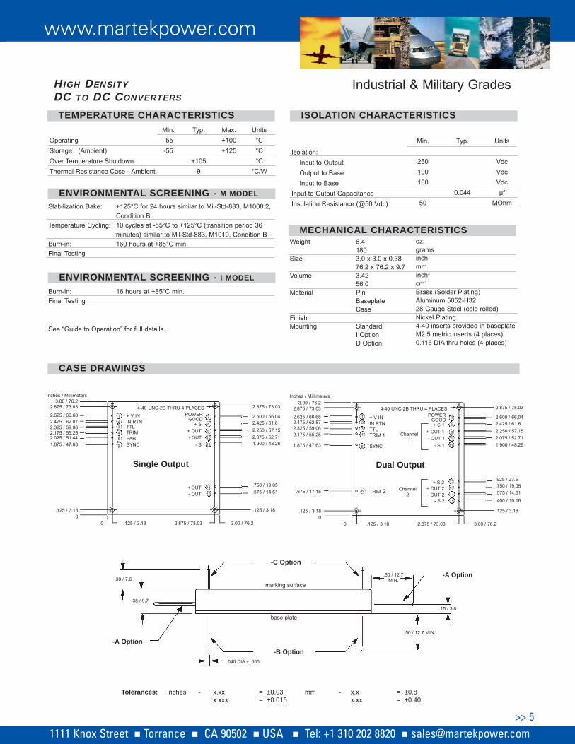
Industrial & Military Grades
Dual Output
8
Channel1
+ OUT 1- OUT 1
Channel2
+ S 2+ OUT 2
11
910
1213
7
- S 1
+ S 1
POWERGOOD
2.875 / 75.03
1.900 / 48.26
2.250 / 57.15
.750 / 19.05
.575 / 14.61
4-40 UNC-2B THRU 4 PLACES
.925 / 23.5
2.075 / 52.71
2.600 / 66.042.425 / 61.6
- OUT 2- S 2
1415
1234
6
+ V ININ RTN
TRIM 2
TTL
5
TRIM 1
SYNC
Tolerances: inches - x.xxx.xxx
= ±0.03= ±0.015
mm - x.xx.xx
= ±0.8= ±0.40
.400 / 10.16
.125 / 3.18
3.00 / 76.22.875 / 73.03.125 / 3.18
3.00 / 76.2
2.625 / 66.68
2.875 / 73.03
2.475 / 62.87
2.175 / 55.25
Inches / Millimeters
1.875 / 47.63
.675 / 17.15
.125 / 3.18
2.325 / 59.06
00
Single Output
8
+ OUT- OUT
+ OUT
11
910
12
7
- S
+ S
POWERGOOD
2.875 / 73.03
2.250 / 57.15
.750 / 19.05
.575 / 14.61
4-40 UNC-2B THRU 4 PLACES
2.075 / 52.71
2.600 / 66.042.425 / 61.6
- OUT 13
1234
+ V ININ RTNTTL
5TRIM
SYNC
.125 / 3.18
3.00 / 76.22.875 / 73.03.125 / 3.18
3.00 / 76.2
2.625 / 66.68
2.875 / 73.03
2.475 / 62.87
2.175 / 55.25
Inches / Millimeters
1.875 / 47.63
.125 / 3.18
2.325 / 59.06
00
1.900 / 48.266
PAR2.025 / 51.44
Min.
250100100
50
Typ.
0.044
Units
VdcVdcVdcμf
MOhm
Isolation:Input to OutputOutput to BaseInput to Base
Input to Output Capacitance Insulation Resistance (@50 Vdc)
TEMPERATEMPERATURE CHARACTERISTICSTURE CHARACTERISTICS ISOLAISOLATION CHARACTERISTICSTION CHARACTERISTICS
CASE DRACASE DRAWINGSWINGS
oz.gramsinchmminch3
cm3
Brass (Solder Plating)Aluminum 5052-H3228 Gauge Steel (cold rolled)Nickel Plating4-40 inserts provided in baseplateM2.5 metric inserts (4 places)0.115 DIA thru holes (4 places)
Weight
Size
Volume
Material
FinishMounting
6.41803.0 x 3.0 x 0.3876.2 x 76.2 x 9.73.4256.0PinBaseplateCase
StandardI OptionD Option
MECHANICALMECHANICAL CHARACTERISTICSCHARACTERISTICS
HIGH DENSITYDC TO DC CONVERTERS
Min.-55-55
Typ.
+1059
Max.+100+125
Units°C°C°C
°C/W
OperatingStorage (Ambient)Over Temperature ShutdownThermal Resistance Case - Ambient
ENVIRONMENTENVIRONMENTALAL SCREENING - SCREENING - M MODELM MODELStabilization Bake: +125°C for 24 hours similar to Mil-Std-883, M1008.2,
Condition BTemperature Cycling: 10 cycles at -55°C to +125°C (transition period 36
minutes) similar to Mil-Std-883, M1010, Condition BBurn-in: 160 hours at +85°C min.Final Testing
ENVIRONMENTENVIRONMENTALAL SCREENING - SCREENING - I I MODELMODEL
Burn-in: 16 hours at +85°C min.Final Testing
See “Guide to Operation” for full details.
www.martekpower.com
>> 51111 Knox Street Torrance CA 90502 USA Tel: +1 310 202 8820 [email protected]

PERFORMANCE CHARACTERISTICS
www.martekpower.com
>> 10
NL550SS NL100 NL1550
IX. TTL Turn On
III. Efficiency vs. Input VoltageII. Efficiency vs. Output PowerI. Input Voltage vs. Output Power
VI. Input Transient ResponseV. Load Transient ResponseIV. Output Voltage Ripple
VII. Input Inrush Current VIII. Input Current Ripple
X. TTL Turn-off XI. Turn-on XII. Turn-off / Hold-up Time
Input Voltage
Effi
cien
cy
120%
100%
80%
60%
40%
90%
85%
80%
75%
70%
65%
60%20% 40% 60% 80% 100%
90%
85%
80%
75%
70%
65%
60%9 10 12 14 16 18
Effi
cien
cy
Output Load Input Voltage
20 m
V/d
iv
Time: 2 μS/div Time: 0.5 mS/div Time: 0.2 mS/div
10 V
/div
0
.1 V
/div
Time: 100 μS/div Time: 2.0 μS/div Time: 0.5 mS/div
20 A
/div
1
0 V
/div
50 m
A/d
iv
2 V
/div
2
V/d
iv2
V/d
iv
5 V
/div
Time: 200 μS/divTime: 0.5 mS/div
2 V
/div
2
V/d
iv
2 V
/div
1
0 V
/div
Vin = 12 Vdc, Vout = 5 Vdc, Iout = 10 A
Vin = 12 Vdc, Vout = 5 Vdc50 - 100% Step Load
Output Current
Output Voltage
Output Voltage
Input Voltage
Vout = 5.0 Vdc, Iout = 10 A9 - 18 V Transient
Vin = 12 Vdc, Vout = 5 Vdc, Iout = 10 A
Input Voltage
Input Current
Vin = 12 Vdc, Vout = 5 Vdc, Iout = 10 A
Vin = 12 Vdc, Vout = 5 Vdc, Iout = 10 A
TTL Signal
Output Voltage
Vin = 12 Vdc, Vout = 5 Vdc, Iout = 10 A
Output Voltage
Input Voltage
Vin = 12 Vdc, Vout = 5 Vdc, Iout = 10 A
Input Voltage
Output Voltage
Vin = 12 Vdc, Vout = 5 Vdc, Iout = 10 A
Output Voltage
TTL Signal
3.3V
5V
0.1
V/d
iv
5 A
/div
4 5 6 7 8 9
2V
Time: 0.2 mS/div
5.2V
15V
12V
Out
put P
ower
2V
3.3V
5.2V
5V 12V
15V
2V
3.3V
5.2V
5V12V
15V
1111 Knox Street Torrance CA 90502 USA Tel: +1 310 202 8820 [email protected]
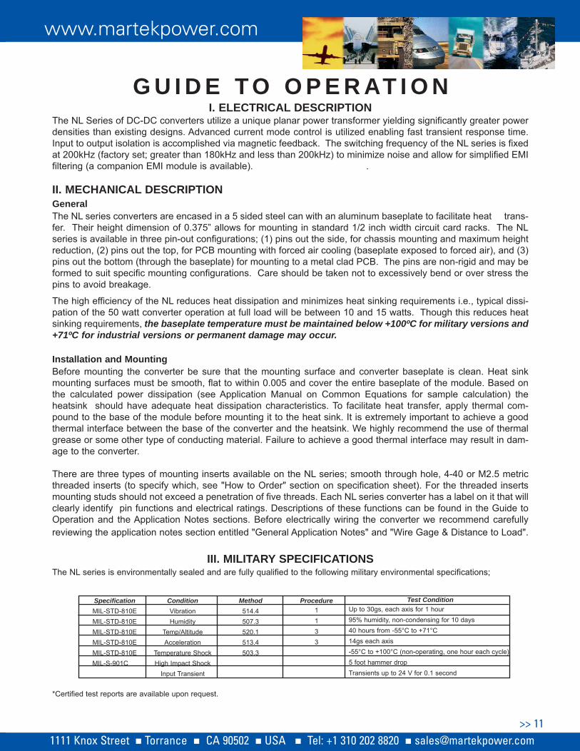
I. ELECTRICAL DESCRIPTIONThe NL Series of DC-DC converters utilize a unique planar power transformer yielding significantly greater powerdensities than existing designs. Advanced current mode control is utilized enabling fast transient response time.Input to output isolation is accomplished via magnetic feedback. The switching frequency of the NL series is fixedat 200kHz (factory set; greater than 180kHz and less than 200kHz) to minimize noise and allow for simplified EMIfiltering (a companion EMI module is available). .
II. MECHANICAL DESCRIPTIONGeneralThe NL series converters are encased in a 5 sided steel can with an aluminum baseplate to facilitate heat trans-fer. Their height dimension of 0.375” allows for mounting in standard 1/2 inch width circuit card racks. The NLseries is available in three pin-out configurations; (1) pins out the side, for chassis mounting and maximum heightreduction, (2) pins out the top, for PCB mounting with forced air cooling (baseplate exposed to forced air), and (3)pins out the bottom (through the baseplate) for mounting to a metal clad PCB. The pins are non-rigid and may beformed to suit specific mounting configurations. Care should be taken not to excessively bend or over stress thepins to avoid breakage.
The high efficiency of the NL reduces heat dissipation and minimizes heat sinking requirements i.e., typical dissi-pation of the 50 watt converter operation at full load will be between 10 and 15 watts. Though this reduces heatsinking requirements, the baseplate temperature must be maintained below +100ºC for military versions and+71ºC for industrial versions or permanent damage may occur.
Installation and MountingBefore mounting the converter be sure that the mounting surface and converter baseplate is clean. Heat sinkmounting surfaces must be smooth, flat to within 0.005 and cover the entire baseplate of the module. Based onthe calculated power dissipation (see Application Manual on Common Equations for sample calculation) theheatsink should have adequate heat dissipation characteristics. To facilitate heat transfer, apply thermal com-pound to the base of the module before mounting it to the heat sink. It is extremely important to achieve a goodthermal interface between the base of the converter and the heatsink. We highly recommend the use of thermalgrease or some other type of conducting material. Failure to achieve a good thermal interface may result in dam-age to the converter.
There are three types of mounting inserts available on the NL series; smooth through hole, 4-40 or M2.5 metricthreaded inserts (to specify which, see "How to Order" section on specification sheet). For the threaded insertsmounting studs should not exceed a penetration of five threads. Each NL series converter has a label on it that willclearly identify pin functions and electrical ratings. Descriptions of these functions can be found in the Guide toOperation and the Application Notes sections. Before electrically wiring the converter we recommend carefullyreviewing the application notes section entitled "General Application Notes" and "Wire Gage & Distance to Load".
III. MILITARY SPECIFICATIONSThe NL series is environmentally sealed and are fully qualified to the following military environmental specifications;
*Certified test reports are available upon request.
G U I D E T O O P E R AT I O N
SpecificationMIL-STD-810EMIL-STD-810EMIL-STD-810EMIL-STD-810EMIL-STD-810EMIL-S-901C
ConditionVibrationHumidity
Temp/AltitudeAcceleration
Temperature ShockHigh Impact Shock
Input Transient
Method514.4507.3520.1513.4503.3
Procedure1133
Test ConditionUp to 30gs, each axis for 1 hour95% humidity, non-condensing for 10 days40 hours from -55°C to +71°C14gs each axis-55°C to +100°C (non-operating, one hour each cycle)5 foot hammer dropTransients up to 24 V for 0.1 second
www.martekpower.com
>> 111111 Knox Street Torrance CA 90502 USA Tel: +1 310 202 8820 [email protected]
The NL series have been tested and found to meet the requirements of Mil-Std-461D for conductedemissions/interference on the input power leads (CE101 and CE102) when used with the appropriate NLF passiveEMI filter. In addition, the series have been fully characterized to Mil-Std-461D for radiated interference (RE101,RE102), conducted susceptibility (CS101, CS114, CS115 and CS116) and radiated susceptibility (RS101, RS103).Full test reports are available upon request that detail our level of compliance for each of these conditions.
IV. PRODUCT FEATURESOutput Voltage Sensing (All models) Output voltage sensing is provided for either local (at the unit) or remote (at the load) sensing. The sense featurecan automatically compensate for up to a 0.5V drop in the leads to the load. The sense pins must be connected(either local or remote) for operation. If remote sensing is not desired it is required to tie the sense pins local-ly, i.e., -sense to -output and +sense to +output. See application notes for more details.
Power Good/Built-in-test (All models) A power good signal (pin) is provided to allow for the monitoring of the output voltage. The power good is set at+5V (referenced to the input return). If the output voltage of the converter drops below 90% of its normal set going(i.e., out of regulation), the power good pin is actively pulled low through a voltage comparator. See applicationnotes for more details.
TTL (Remote on/off) (All Models)The TTL feature is used to command the NL series on and off and is referenced to the input return. When the TTLpin is left unconnected or, if a voltage between 2.4V and 5.0V is applied to the pin, the converter will remain on.When the TTL pin is pulled down below 0.8V the unit will turn off. See application notes for more details.
Parallel Operation (NL50, 100 and 150 Single Outputs)A parallel circuit is provided to allow for parallel operation to achieve higher output power or N+1 redundancy.Parallel operation is accomplished by connecting all the parallel pins together (single pin wiring), allsynchronization pins together and connecting all input power leads (+ and - leads) together. Units will parallelbetween ±10% of total output power current.
Over Temperature Protection (All Models)An integral electronic over temperature shut down circuit is provided to protect the NL series from accidental overheating. If the temperature (measured at the baseplate) of the converter exceeds 5% above the rated highoperating temperature, the unit will automatically shut down. Once the temperature (measured at the baseplate)is reduced to 85%, of the rated high operating temperature, power will be automatically restored.
Output Voltage Trim (All Models)An output voltage trim pin is provided for the adjustment of the output voltage. Using this feature the output volt-age can be trimmed up to 110% (trim is only available to increase the output voltage) of nominal. To increase theoutput voltage of the NL series, simply attach a resistor between the trim pin and the input return of the unit. Seeapplication notes for more details.
Switching Frequency Synchronization (All models)The NL series switching frequency is factory set greater than 180kHz but less than 200kHz. The synchronizationclock will be at twice the switching frequency. If desired, several NL units may be synchronized to the same switch-ing frequency by wiring all of the sync pins together and wiring all input returns of the units together. The unit whichis switching at the fastest rate will automatically become the “master” and will adjust the remaining units to switchat the same (higher) frequency. Also, the frequency of the synchronized units may be increased by injecting ahigher frequency pulsed waveform into the sync pin. See application notes for more details.
Overload/Short Circuit Protection (All Models)The output of the NL Series is protected from an accidental overload or short circuit condition of any duration.When the output load exceeds the full load capability of the supply (between 105% to 150% of the maximum rated
www.martekpower.com
>> 121111 Knox Street Torrance CA 90502 USA Tel: +1 310 202 8820 [email protected]

output current) the converter switches into a “Burp-Mode” (this is where the converter is sensing the overload andis continuously turning on and off in a controlled fashion). When the overload/short circuit is removed theconverter automatically returns to its normal mode of operation.
Over Voltage Protection (All Models)The NL series provides an internal “Latching” output overvoltage protection circuit. Should an output overvoltagecondition occur, the converter will shut off. Input must be recycled to restore output.
V. RELIABILITYReliability CalculationIn order to achieve superior reliability, the NL series converters adhere to the stringent component deratingguidelines of NAVMAT P4855-1.The Mean Time Between Failure (MTBF) per Mil-HBDK-217F Notice 2 for the NLSeries under the operating conditions of 50ºC baseplate, maximum rated output power for a ground benignenvironment is calculated in the following table. Test reports for all models are available upon request.
Standard Military Grade Module ScreeningEach military grade NL module under goes environmental screening based upon the parameters outlined inMil-Std-883 and NAVMAT P4855-1. The screening and process steps consist of the following;
1. STABILIZATION BAKE; +125°C FOR 24 HOURS PER MIL-STD-883, M1008.2 CONDITION B
2. VOLTAGE ISOLATION AND PARAMETRIC TESTING AT 25°C
3. MODULE ENCAPSULATION
4. TEMPERATURE CYCLING (NON-OPERATIONAL); 10 CYCLES MINIMUM, AT -55°C TO +125°C, 36 MINUTETRANSITION WITH A 1 HOUR DWELL AT EACH TEMPERATURE EXTREME. PROCEDURE REFERENCE MIL-STD-883,M1010, CONDITION B AND NAVMAT P4855-1.
5. VOLTAGE ISOLATION AND PARAMETRIC TESTING AT 25°C
6. LONG TERM OPERATIONAL BURN IN; 160 HOURS OF POWERED OPERATION UNDER LOAD. MODULES ARECONTINUOUSLY CYCLED FROM +85°C TO THERMAL SHUT DOWN POINT (+105°C) DURING THE 160 HOURS.
7. VOLTAGE ISOLATION AND PARAMETRIC TESTING AT 25°C
8. VISUAL INSPECTION
Additional testing is available including parametric testing at temperature or extended burn in time. Consultfactory for more information. Additional testing or customer specific testing will require additional charges.
Accelerated Life TestingAn accelerated life test was performed on representative sample units of the NL series to determine the long-termeffects on performance. Units were subjected to 450 thermal cycles (non-operational) of -55°C to +125°C, and 50thermal cycles (operational) between -55°C and 70°C. At every 50th cycle modules were given full parametrictesting. At the conclusion of the 500th cycle modules were found to operate within published specifications.
Additional qualifications tests include: monitored, 3 axis, random vibration with power applied at full output load;25 thermal shock cycles between -55 and 125°C (non operational) and 2200 hour (3 month) high temperatureburn-in at full output load.
MODELNL50SM (Military)NL50SI (Industrial)
MTBF HOURS1,770,000567,000
www.martekpower.com
>> 131111 Knox Street Torrance CA 90502 USA Tel: +1 310 202 8820 [email protected]

A P P L I C AT I O N N O T E S
General Application Notes...........................................................................15
Wire Gage & Distance to Load......................................................................15
Ripple & Noise...............................................................................................16
Remote Sense...............................................................................................17
Remote On/Off..............................................................................................17
Output Trim...................................................................................................18
Series Operation...........................................................................................19
Parallel Operation.......................................................................................19
Synchronization.............................................................................19
Power Good Signal.......................................................................................20
Electro Magnetic Filter (EMI) NLF50/150..................................................20
Trim Values...................................................................................................21
Applications Manual......................................................................................22
Block Diagram.............................................................................................23
Frequently Asked Questions........................................................................24
www.martekpower.com
>> 141111 Knox Street Torrance CA 90502 USA Tel: +1 310 202 8820 [email protected]

General General Application NotesApplication NotesThe NL Series of DC-DC converters utilize a uniqueplanar power transformer yielding significantly greaterpower densities than existing designs. Advanced modecontrol is utilized enabling fast transient response time.Input to output isolation is accomplished via magneticfeedback. The switching frequency of the NL series isfixed at 200kHz (factory set; greater than 180kHz butless than 200kHz) to minimize noise and allow forsimplified EMI filtering (a companion EMI module isavailable). Sufficient capacitance on the input andoutput, internal to the unit, allows for simple use andoperation with no external components in mostapplications.
The NL units are supplied in a five sided metal case tominimize radiated noise. The height dimension of 0.375"allows for mounting in standard 1/2 inch width circuitcard racks. The NL is available in three pin-out configu-rations; 1) pins out the side for chassis mounting andmaximum height reduction, 2) pins out the top for PCBmounting with forced air cooling (baseplate exposed toforced air), and 3) pins out the bottom (through the base-plate) for conduction cooling via a metal clad board. Thehigh efficiency of the NL reduces head dissipation andminimizes heat sinking requirements i.e., maximumdissipation of the 50 watt converter will be between 10and 15 watts. A number of protection features, as well aselectrical and thermal derating of internal componentsallows for high reliability throughout the entire operatingranges. There are two operating ranges available, -40°C to +71°C (for industrial applications) and -55 °C to+100 °C (for military applications). Qualification testreports to Mil-Std-810E and Mil-Std-901C are availableon request.
The most basic use of the power converter is shown infigure 1. An input fuse is always recommended toprotect both the source and the power supply in theevent of failures. Bus fuse type MDX or equivalentslow-blow is recommended with a current ratingapproximately 200% of the full load input current to theconverter. Having a slow-blow type fuse will allow for theconverter's inrush charge at turn-on.
The sense pins of the converter must be connected totheir corresponding output bus. Inherently, powerconverters will have some internal energy loss, which isdissipated in the form of heat through an aluminummounting surface. This surface must be cooled to main-tain a temperature below the maximum operatingtemperature. ,
WWire Gage & ire Gage & DistDistance to Loadance to Load
If the resistance of the wire, printed circuit board runs orconnectors used to connect a converter to systemcomponents is too high, excessive voltage drop willresult between the converter and system components,degrading overall system performance.
For example, if the DC/DC converter in Figure 1a is a50W unit (5 VDC @ 10 Amps) with output load regulationspecified at 0.2%; the connection as shown will degradeload regulation by a factor of 10. In this example, the 4feet of #14 AWG wire used to connect the converter out-put to the load, has a total line resistance of 10 mW(ignoring any contact resistance). For a 50W, 5VDC out-put converter, the drop across the lead resistance will be100 mV (10 A X 0.010W) or 2% of the output. Thus, theconverter was selected for 0.2% regulation, but thepower system layout achieves only 2.2%.
This can be corrected by decreasing the distancebetween the converter output and load. If that is notpossible, using larger diameter wire (see table 1), orPCB runs that have a larger cross sectional area andshorter length will also reduce conductor resistance. The
Figure 1
Basic Converter Hook-up
Figure 1a
Basic Hook-up
www.martekpower.com
>> 151111 Knox Street Torrance CA 90502 USA Tel: +1 310 202 8820 [email protected]

use of the converter's remote sense capability will alsowork (see remote sense for more information on thisoption).
Obviously, any connections made to the powerdistribution bus may present a problem. Poor connec-tions (such as microcracking around solder joints) cancause serious problems such as arcing. Contactresistance must be minimized. Proper workmanshipstandards must be followed to insure reliable solderjoints for board mount converters.
Terminal strips, spade lugs and edge connectors mustbe free of any corrosion, dust or dirt. If parallel lines orconnections are available for routing converter outputcurrents, they should be utilized.
Ripple & NoiseRipple & NoiseOutput ripple and noise (sometimes referred to asPARD or “Periodic and Random Deviations”) can bedefined as unwanted variations in the output voltage ofa power supply. In switching power supplies this outputnoise is seen as a series of pulses with a high frequen-cy content and is therefore measured as a peak value(i.e., specified as “peak-to-peak”).
Abbott power supplies are specified and tested in ourfactory with a 25 MHz or 10 Mhz bandwidthoscilloscope. Measurements taken by a scope set athigher frequencies (i.e. 300 MHz) may producesignificantly different results due to noise coupling on to
the probe from sources other than the power supply.
Noise that is common to all output leads of a powerconverter with respect to the chassis is referred to ascommon mode noise. Noise that is apparent on oneoutput lead with respect to corresponding output lead isreferred to differential mode noise. Common modenoise is produced in switching action. Abbott typicallyminimizes the level of output common mode noise byincorporating line to chassis ground capacitors (on inputand output leads) into the power converters. In mostcases this is sufficient to minimize the level of commonmode noise, however if further attenuation is requiredadditional line to chassis ground capacitance may beadded by the customer at the system level. Abbott noisespecifications (output ripple specifications) all referencethe level of differential mode noise at a given bandwidth,not the level of common mode noise. The measurementof differential mode noise is detailed in the followingparagraphs.
Measurement Techniques
The length of all measurements leads (especially theground lead) should be minimized and the sense pinsshould be tied to their respective outputs (+Sense to +Vout). We recommend measurement as close to thesupply as possible. This can be accomplished by con-necting a short bus wire (generally 0.5 inches or less,making a loop at the end to place in the probe) to thenegative and positive outputs on the back side of theconnector mate, then place the tip of the probe on the+output and ground ring (or ground band) on the-output for a true ripple measurement. This is displayed infigure 1b;
Utilizing the probe ground ring (as opposed to a groundwire) will minimize the chance of noise coupling fromsources other than the power supply. If this is not prac-tical or possible then attach a 6 to 8 inch twisted pairwire to the outputs of the power supply and place a 10-
#AWG9
1011121314151617181920
CurrentResistance
mΩΩ/Foot0.7920.9981.2611.5582.0012.5243.1814.0205.0546.3868.04610.13
#AWG212223242526272829303132
CurrentResistance
mΩΩ/Foot12.7716.2020.3025.6732.3741.0251.4465.3181.21103.7130.9162.0
Table 1
Note: High IR drops between the converter and load maycause converter parameters such as output voltage accu-racy, trim range, etc. to appear to be out of specification.High IR drops on input lines may cause start up problems(voltage at the input pins below the input range of the con-verter).
Figure 1b
+ S
+ OUT
- OUT
- S
ProbeGround Ring
Sense TiedLocal
www.martekpower.com
>> 161111 Knox Street Torrance CA 90502 USA Tel: +1 310 202 8820 [email protected]

20 uF tantalum capacitor (low ESR type, with an appro-priate voltage rating) across the load. This test methodis shown on figure 1c.
This test method will enable a remote measurementand eliminate any noise that may couple on to theextended leads coming off the converter.
Ripple Reduction Techniques
In applications where the output ripple of the converteris higher then desired various techniques can beemployed to reduce output ripple and noise (PARD).One method is to add additional capacitance in parallelwith the output leads of the converter (low ESR typetantalums or ceramics are recommended). This shouldsubstantially reduce PARD, but be aware that excessiveadditional output capacitance can cause converteroscillations (see table 2 for the maximum allowablecapacitance that may be added to the output leads andfor typical output ripple values with this capacitanceadded).
Another way to reduce PARD is to use Martek PowerAbbott’s output ripple attenuator module, SMRA (seetable 3 for typical output ripple values while using theSMRA with an NL series 50 watt channel. Full specifi-cations for the SMRA module can be found in the SMseries data book).
Remote SenseRemote SenseRemote sense pins, +S and -S have been provided onthe NL Series converters for applications where preciseload regulation is required at a distance from where theconverter is physically located. If remote sensing isNOT required, these pins MUST be tied to their respec-tive output pins (+S to +OUT and -S to -OUT). If one ormore of these sense pins are not connected to theirrespective output pins, the output(s) of the unit will notregulate to within specification and may cause a highoutput voltage condition.
•DO NOT connect sense pins to any pin other than theirrespective output pins or permanent damage will occur.
•DO NOT connect sense pins to any load other than thesame load the output pins are connected to orpermanent damage may occur.
The internal remote sense circuit is designed to com-pensate for a maximum of 0.5V difference (0.25V ineach output lead) in voltage between the load and thepower converter. Longer output leads or traces arerequired to be of sufficient gauge or width to maintainthe voltage drop across them of 0.5V maximum at ratedload current.
Remote On/OffRemote On/OffRemote turn ON/ turn OFF feature (TTL) is an addition-al feature of the NL Series. This feature is especiallyuseful in portable/mobile applications where batterypower conservation is critical or in applications involvinghigh power pulsed loads where inrush currents arehigh.
Figure 2
Remote Sense - Single OutputFigure 1c
Twisted Pair Wire
6-8 inches
ProbeGround Ring
Probe Tip20 UF Capacitor
low ESR
+ S+ OUT
- OUT- S
Table 2
Output Voltage
2V3.3V5V
5.2V12V15V
Typical Vp-p@10MHZ (full load, nominal input voltage)
15mV20mV15mV15mV15mV15mV
Table 3
Output Voltage
2V3.3V5V
5.2V12V15V
Maximum Capacitance per 50W channel
1100uF1100uF1100uF1100uF110uF75uF
Typical Vp-p@10MHZ(full load, nominal input voltage)
15mV20mV20mV20mV20mV20mV
www.martekpower.com
>> 171111 Knox Street Torrance CA 90502 USA Tel: +1 310 202 8820 [email protected]

The NL Series employs a typical TTL open collectorwith positive logic control pin. The voltage level at theTTL pin is referenced with respect to the converter -VINinput. When the TTL circuit is pulled to less than 0.8 V("logic 0") with respect to the - VIN pin, via either anopen collector (see figure 3), or totem-pole driver, or amechanical switch, with a 100μA capability, the con-verter shuts down. An optocoupler can also be used ifthe TTL signal needs to be referenced from the outputside. If the TTL pin is left floating or is pulled above2.4V up to 5.0V (‘logic 1’) the unit will remain on. Manymore devices can be used to activate the TTL pin shut-down function, consult the factory for your specificrequirements. When employing multiple NL moduleswhich are to be turned on and off at the same time, tiethe TTL pins of every module together.
Output TOutput Trimrim
TT he output voltage is increased by simply con-necting a resistor between the trim pin and the
input voltage pin (see figure 4).
The value of the resistor required is determined byusing the equation below.
R3(R2+R4-R2VOUT)+R4R2
R*(NL50S) = R2(VOUT-1)-R4
R* R*R(NL100S) = 2 R(NL150S) = 3
The values of R2, R3 and R4 are output voltagedependent per the following table:
Resistor values for trim ranges have been calculat-ed for your reference on page 24.
Example 1:
We have a NL50S with a 12 volt output but need trim-ming up to 13 Vdc. The equation would be as follows,
8.25K(3.65K + 39K - 3.65K(13)) + 39K(3.65K)R = 3.65K(13 - 1) - 39K
R = 21.41KΩ
By using a 21.41KΩ resistor for the trim resistor R, theoutput voltage will be 13 Vdc.
Figure 4a shows a scheme for a continuously variableoutput from 100% to 110% of nominal output voltage(voltages higher than 110% may activate the overvolt-age protection circuit).
Note: The equation for R is valid for the NL50S, 100D and150T. For the NL100S and 150S, use the R(NL100S) andR(NL150S) equations accordingly.
Basic Trim
Figure 3
Remote Turn On/Off
VOUT
2V3.3V5V
5.2V12V15V
R2
20K8.25K10K10K
3.65K2.74K
R3
20K20K20K20K
8.25K8.25K
R4
18.70K18.70K39.0K39.0K39.0K39.0K
Figure 4
www.martekpower.com
>> 181111 Knox Street Torrance CA 90502 USA Tel: +1 310 202 8820 [email protected]

Series OperationSeries OperationThe NL family of power converters may be arranged ina series operating mode to supply higher output volt-ages when required (see figure 5). In this configurationD1 and D2 are added to protect against the applicationof a negative voltage across the outputs of the powerconverters during power up and power down. The two(or more) units need not have the same output voltage,but the output current supplied in this configuration willbe limited to the lowest maximum output current of themodules used.
Parallel OperationParallel OperationThe NL Series converter has the capability of beingparalleled to drive loads of higher power. The PAR pinis supplied on the unit for this function. If parallel oper-ation of two or more units is required, the following pre-cautions must be followed. (NOTE: It is not recom-mended to parallel more than five 50 watt units or two100 watt units. The 150 watt units may be paralleled toa maximum power level of 250 watts.)
• Corresponding input and output leads or traces oneach unit should be as equal in length and size as practical. The more equivalent the leads are thecloser the current sharing.
• The leads connecting the PAR, SYNC and -IN pins may need to be shielded to avoid high frequency noise interference in very high power applications.
• The PAR, SYNC and -IN pins of all units should be tied together.
OR-ing diodes may be included in the positive outputleads for true N+1 redundant systems, but are not nec-essary. Local sensing should be used whenever pos-sible to minimize noise on +S and -S pins in parallelapplications. In some applications, especially in thosewhere it is difficult to keep output and input leads ofequal size and length, a series resistance may beinserted in the +S lead. This will give the converter theability to compensate for lead imbalance. Note: thiswill also result in a slightly higher output voltage.
SynchronizationSynchronizationSynchronization of multiple units to each other or to acentral clock frequency is essential in noise sensitivesystems. The NL Series units are capable of being syn-chronized to each other by tying the SYNC and -IN pinstogether. This will synchronize all of the units together(see figure 7).
Figure 5
Series Operation
Variable Trimming
Figure 4a
Figure 6
Parallel Operation
www.martekpower.com
>> 191111 Knox Street Torrance CA 90502 USA Tel: +1 310 202 8820 [email protected]

The NL Series converter can be tied to the central clock(see figure 7a) by inputting a square wave clock signal(standard TTL levels of ‘0V’ and ‘5V’ are recommended)which has a frequency of 400 kHz or greater (a periodof 2.5 μS or lower) and a duty cycle of no less than 10%(a pulse width of greater than 0.25μS). The NL Seriesconverter’s internal synchronization circuit is triggeredby the rising edge of this clock waveform. Thefrequency can be increased by the external clockbetween the frequency range of 400-420 KHz. Theinput resistance of the SYNC pin for each NL50S is 110ohm. Higher frequencies make the unit less noisetolerant and care should be taken in how the SYNC pinline is connected between units and/or system clock. Insome cases shielding the SYNC pin line will helpeliminate the noise. Do not add any capacitance fromthe SYNC pin line to ground.
Power Good SignalPower Good SignalThe power good signal is provided to allow for themonitoring of the output voltage. The power good is setto +5V (referenced to the input return) whenever the
output of the unit is above 90% of its nominal value.
If the output voltage falls below this point the powergood pin is actively pulled low. Also, if the output over-voltage circuit triggers due to an overvoltage conditionthe power good pin is actively pulled low.
See figure 8 for a schematic of the power good circuityinternal to the unit. This figure shows a comparator witha series resistance of 210Ω to the external power goodpin. When multiple channels are utilized the powergood circuitry is connected as shown (i.e., the NL150Thas three channels and therefore has three power goodcircuits connected together internal to the unit).
Electro Magnetic Filter (EMI)Electro Magnetic Filter (EMI)NLF50 & NLF150NLF50 & NLF150
For applications where electromagnetic interference isa concern, the NLF (50 and 150 watt capable), apassive input line filter, may be installed at the input ofthe NL series converter (see figure 9). With the NLFMil-Std-461D, CE101-4 and CE102 are withincompliance on the input leads. Test reportscharacterizing both filters for conducted and radiatedemission and susceptibility are available. Filtersguarantee conducted emissions (on the input leads)only. All test reports are certified by an independenttesting lab.
Figure 9
NLF Connection
Figure 8
Power Good
Channel1
Channel2....
Channel5
.
.
.
.
LM393
LM393
LM393
Comparator
Comparator
Comparator
5.1V
5.1V
5.1V
210ΩΩ
210ΩΩ
210ΩΩ10kΩΩ
10kΩΩ
10kΩΩ
PowerGoodOutput
Figure 7
Synchronization of NL Units
www.martekpower.com
>> 20
Synchronization to External Clock
1111 Knox Street Torrance CA 90502 USA Tel: +1 310 202 8820 [email protected]

2 V U N I T1.00% 2.00% 3.00% 4.00% 5.00% 6.00% 7.00% 8.00% 9.00% 10.00%
R2 20000 41980 41980 41980 41980 41980 41980 41980 41980 41980R3 20000 20000 20000 20000 20000 20000 20000 20000 20000 20000R4 20000 20000 20000 20000 20000 20000 20000 20000 20000 20000VOUT 2.02 2.04 2.06 2.08 2.1 2.12 2.14 2.16 2.18 2.2R TRIM (50S) 980000 15487 14271 13135 12073 11076 10139 9258 8426 7640R TRIM (100S) 490000 7744 7136 6568 6036 5538 5070 4629 4213 3820R TRIM (150S) 326667 5162 4757 4378 4024 3692 3380 3086 2809 2547
3 . 3 V U N I T1.00% 2.00% 3.00% 4.00% 5.00% 6.00% 7.00% 8.00% 9.00% 10.00%
R2 8250 8250 8250 8250 8250 8250 8250 8250 8250 8250R3 20000 20000 20000 20000 20000 20000 20000 20000 20000 20000R4 18975 18975 18975 18975 18975 18975 18975 18975 18975 18975VOUT 3.33 3.37 3.4 3.43 3.47 3.5 3.53 3.56 3.6 3.63R TRIM (50S) 612500 251071 169750 125962 91618 74875 62500 52981 43250 37500R TRIM (100S) 306250 125536 84875 62981 45809 37438 31250 26490 21625 18750R TRIM (150S) 204167 83690 56583 41987 30539 24958 20833 17660 14417 12500
5 V U N I T1.00% 2.00% 3.00% 4.00% 5.00% 6.00% 7.00% 8.00% 9.00% 10.00%
R2 10000 10000 10000 10000 10000 10000 10000 10000 10000 10000R3 20000 20000 20000 20000 20000 20000 20000 20000 20000 20000R4 40000 40000 40000 40000 40000 40000 40000 40000 40000 40000VOUT 5.05 5.1 5.15 5.2 5.25 5.3 5.35 5.4 5.45 5.5R TRIM (50S) 780000 380000 246667 180000 140000 113333 94286 80000 68889 60000R TRIM (100S) 390000 190000 123333 90000 70000 56667 47143 40000 34444 30000R TRIM (150S) 260000 126667 82222 60000 46667 37778 31429 26667 22963 20000
5 . 2 V U N I T1.00% 2.00% 3.00% 4.00% 5.00% 6.00% 7.00% 8.00% 9.00% 10.00%
R2 10000 10000 10000 10000 10000 10000 10000 10000 10000 10000R3 20000 20000 20000 20000 20000 20000 20000 20000 20000 20000R4 40500 40500 40500 40500 40500 40500 40500 40500 40500 40500VOUT 5.25 5.3 5.36 5.41 5.46 5.51 5.56 5.62 5.67 5.72R TRIM (50S) 182500 142000 110645 92500 78780 68043 59412 51053 45323 40448R TRIM (100S) 91250 71000 55323 46250 39390 34022 29706 25526 22661 20224R TRIM (150S) 60833 47333 36882 30833 26260 22681 19804 17018 15108 13483
1 2 V U N I T1.00% 2.00% 3.00% 4.00% 5.00% 6.00% 7.00% 8.00% 9.00% 10.00%
R2 3650 3650 3650 3650 3650 3650 3650 3650 3650 3650R3 8250 8250 8250 8250 8250 8250 8250 8250 8250 8250R4 40150 40150 40150 40150 40150 40150 40150 40150 40150 40150VOUT 12.12 12.24 12.36 12.48 12.6 12.72 12.84 12.96 13.08 13.2R TRIM (50S) 326333 159042 103278 75396 58667 47514 39548 33573 28926 25208R TRIM (100S) 163167 79521 51639 37698 29333 23757 19774 16786 14463 12604R TRIM (150S) 108778 53014 34426 25132 19556 15838 13183 11191 9642 8403
1 5 V U N I T1.00% 2.00% 3.00% 4.00% 5.00% 6.00% 7.00% 8.00% 9.00% 10.00%
R2 2740 2740 2740 2740 2740 2740 2740 2740 2740 2740R3 8250 8250 8250 8250 8250 8250 8250 8250 8250 8250R4 38360 38360 38360 38360 38360 38360 38360 38360 38360 38360VOUT 15.15 15.3 15.45 15.6 15.75 15.9 16.05 16.2 16.35 16.5R TRIM (50S) 247483 119617 76994 55683 42897 34372 28283 23717 20165 17323R TRIM (100S) 123742 59808 38497 27842 21448 17186 14142 11858 10082 8662R TRIM (150S) 82494 39872 25665 18561 14299 11457 9428 7906 6722 5774
T R I M V A L U E S
www.martekpower.com
>> 211111 Knox Street Torrance CA 90502 USA Tel: +1 310 202 8820 [email protected]

Common EquationsCommon EquationsCalculation of Input Current
Calculating the required current draw for your converter is as follows.
Maximum Input current =
The above calculation will yield the converter's input current. For Example;Model: NL50SM/5-COutput Power: 50 wattsSteady State Line: 12 VDCEfficiency; 78% at 12 VDC line, full load (see tables in Performance Characteristics) assuming 5% safety factorefficiency is then 73%Steady State Input Line: 12 VDC
Input Current = Input Current = 5.71 amps
The worst case steady state input current to the NL series converter operating at full load with an input of 12 VDCis 5.71 amps.
Note: it is always best to be conservative. The figures for input voltage and efficiency should always include someadditional margin for error.
Power Dissipation
The calculation of the total power dissipated from the converter will be essential for thermal management of thedevice. Unlike other types of electronic devices DC/DC converters tend to generate a significant amount of heat.This heat is channeled (by design) to the bottom or baseplate of the module. The following equations assist whendesigning a suitable heat sink.
The basic equation is;
PDiss = Pin - Pout
Where Pout is defined as the maximum load condition and Pin is defined as a function of Pout and efficiency. Theequation is therefore;
PDiss =
The energy loss calculated from the above equation will be dissipated via the converter's baseplate in the form ofheat. A key parameter in this equation is the converter efficiency. Efficiency will be dependent upon the line andload characteristics of the application.
The above calculation will yield the converter's power dissipation. For example; Model: NL150SM/5-COutput Power: 150 wattsEfficiency; 78% at 12 VDC line, 100% load (see tables in Performance Characteristics) assuming 5% safetyfactor efficiency is then 73%
PDiss = PDiss = 55.48 watts
The maximum power dissipated from the converter under these conditions will be 55.5 watts.
A P P L I C A T I O N S M A N U A L
Output PowerEfficiency
Minimum Steady StateInput Line
Pout
Efficiency- Pout
1500.73 - 150
50 watts0.73
12 VDC
www.martekpower.com
>> 221111 Knox Street Torrance CA 90502 USA Tel: +1 310 202 8820 [email protected]

B L O C K D I A G R A M
50 50 watt Channel(s)watt Channel(s)
POWER STAGE
CURRENT MODECONTROLLER
STARTREGULATOR
SCP
OVER TEMPSHUTDOWN
LATCHINGOVERVOLTAGE
SHUTDOWN
MAGNETICISOLATION
POWERGOOD
GATEDRIVE
+ Vin
VinRETURN
(9-18 Vdc)
+ VOUT
RETURN
+ SENSE
- SENSE
1
(2V-15Vdc)
SYNC
PARALLEL
TTL
Vout TRIM
2
1
1 Input to Output Voltage Isolation Boundry
www.martekpower.com
>> 231111 Knox Street Torrance CA 90502 USA Tel: +1 310 202 8820 [email protected]

Can I measure output voltage without any load connected to the unit?Yes, all NL modules regulate to the specified output voltage under "no load' conditions.
Can I connect the input ground to the output ground or to chassis ground?Yes, the input, output and chassis grounds are isolated up 100 VDC minimum (see specification sheet) and may be tied together in any manner.
Are any additional components required to operate the NL modules?No, the NL series was designed for full operational performance without the need for additional components.
Are any additional components recommended to enhance operation?This will depend on your application. For noise sensitive systems we would recommend the use of bypass capacitors inparallel with the output leads of the converter (low ESR type). This will reduce the effects of noise on the output lines. Forapplications where the power source is located a significant distance away for the converter modules it may be desirableto add bypass capacitors in parallel with the input leads. Lastly, series operation clamping diodes can be included to pro-tect against reverse voltage conditions (see series operation note in the applications section).
At the output of the converter I have a hold up capacitor in parallel with my load. Will this cause a problem?It might! Though a small amount of capacitance in parallel with the output will improve (reduce) noise performance, if thecapacitor is too large it may cause the converter to trip its' over load protection circuit. If this happens it will appear as a"no output" condition. If you suspect that this is happening we suggest you remove the hold up capacitor from the line. Theconverter will then recover immediately.
The module's output voltage drops to zero at high temperature but when the unit cools down the output returns.What's causing this problem?The thermal protection circuit (described in the Over Temperature Protection section in the Guide to Operation) is engag-ing. This circuit will activate when the baseplate exceeds it maximum operating temperature (71°C for industrial and 100°Cfor military versions). To verify this you must measure the temperature at the center of the baseplate with a calibrated tem-perature probe. The center is the converter's "hot spot" and is the monitoring point for the thermal protection circuit.Measurements taken at other locations of the device will be lower by as much as 10°C. Also, be sure that the probe issecurely in contact with the converter's base minimizing contact with any other thermally conductive material while takingthe measurement.
How many NL modules can be used with each EMI filter?The NLF EMI filters are not specified for a maximum number of units but rather a maximum output power capability. Aslong as the total power draw does not exceed the filter rating the filter will perform to specification.
If I don't want to use some of the features of the NL converter (TRIM, TTL, PAR, SYNC or POWER GOOD) do I stillhave to connect the pins?No, for full operating performance all that needs to be connected is the two (2) input pins, the two to six (2/6) output pins(depending on output power) and the two to six (2/6) sense pins connected to either the load or the respective +/- outputpins. You MUST connect all output pins provided to ensure reliable operation. The remaining pins may be left open (or cutfor mounting purposes).
I need to use an input EMI filter in front of the converter. Do you have a suggested circuit?Abbott offers passive EMI filters (NLF modules) that are designed to operate in conjunction with our modules to providecompliance to Mil-Std-461D, conducted emissions (CE101 and CE102) on the input leads. Many customers have suc-cessfully designed their own filter however, we advise care when doing so. Any circuit between the power source and theinput to the converter has the potential to cause operational problems (such as filter/converter oscillations). In addition, anycomponents in line with the converter will cause a voltage drop and this must be taken into account when considering lowline operation. For example, the input to the NL50 series converter is 9 to 18 VDC. When an NLF50 filter is added in linewith the converter the low line input voltage at the input of the filter should be at least 10 VDC to account for the 1.0 VDCdrop across the filter.
What level of transient protection is the NL series capable of withstanding?The converter alone can withstand a transient of 24 VDC for 100 mS.
FREQUENTLY ASKED QUESTIONSQ-A-
Q-A-
Q- A-
Q- A-
Q- A-
Q-
A-
Q- A-
Q-
A-
Q- A-
Q- A-
www.martekpower.com
>> 241111 Knox Street Torrance CA 90502 USA Tel: +1 310 202 8820 [email protected]