NEURAL NETWORK BASED SEMI-ACTIVE CONTROL...
13
COMPDYN 2011 3 rd ECCOMAS Thematic Conference on Computational Methods in Structural Dynamics and Earthquake Engineering M. Papadrakakis, M. Fragiadakis, V. Plevris (eds.) Corfu, Greece, 25–28 May 2011 NEURAL NETWORK BASED SEMI-ACTIVE CONTROL STRATEGY FOR STRUCTURAL VIBRATION MITIGATION WITH MAGNETORHEOLOGICAL DAMPER SUBRATA BHOWMIK Department of Mechanical Engineering, Technical University of Denmark 403 Nils Koppens Allé, Lyngby, Denmark 2800 e-mail: [email protected] Keywords: Magnetorheological damper, neural network, semi-active control. Abstract. This paper presents a neural network based semi-active control method for a rota- ry type magnetorheological (MR) damper. The characteristics of the MR damper are de- scribed by the classic Bouc-Wen model, and the performance of the proposed control method is evaluated in terms of a base exited shear frame structure. As demonstrated in the literature effective damping of flexible structures is obtained by a suitable combination of pure friction and negative damper stiffness. This damper model is rate-independent and fully described by the desired shape of the hysteresis loops or force-displacement trajectories. The proposed neural network controller is therefore trained based on data derived from these desired force- displacement curves, where the optimal relation between friction force level and response amplitude is determined explicitly by simply maximizing the damping ratio of the targeted vi- bration mode of the structure. The neural network control is then developed to reproduce the desired force based on damper displacement and velocity as network input, and it is therefore referred to as an amplitude dependent model reference control method. An inverse model of the MR damper is needed to determine the damper current based on the derived optimal damper force. For that reason an inverse MR damper model is also designed based on the neural network identification of the particular rotary MR damper. The performance of the proposed controller is compared to that of an optimal pure viscous damper. The top floor dis- placement and acceleration of the base excited shear frame structure are selected as the per- formance parameters of this comparison. It is found by the simulations that the proposed control design yields a reduction in the structural response compared to the viscous case.
Transcript of NEURAL NETWORK BASED SEMI-ACTIVE CONTROL...
COMPDYN 2011 3rd ECCOMAS Thematic Conference on
Computational Methods in Structural Dynamics and Earthquake Engineering M. Papadrakakis, M. Fragiadakis, V. Plevris (eds.)
Corfu, Greece, 25–28 May 2011
NEURAL NETWORK BASED SEMI-ACTIVE CONTROL STRATEGY FOR STRUCTURAL VIBRATION MITIGATION WITH
MAGNETORHEOLOGICAL DAMPER
SUBRATA BHOWMIK
Department of Mechanical Engineering, Technical University of Denmark 403 Nils Koppens Allé, Lyngby, Denmark 2800
e-mail: [email protected]
Keywords: Magnetorheological damper, neural network, semi-active control.
Abstract. This paper presents a neural network based semi-active control method for a rota-ry type magnetorheological (MR) damper. The characteristics of the MR damper are de-scribed by the classic Bouc-Wen model, and the performance of the proposed control method is evaluated in terms of a base exited shear frame structure. As demonstrated in the literature effective damping of flexible structures is obtained by a suitable combination of pure friction and negative damper stiffness. This damper model is rate-independent and fully described by the desired shape of the hysteresis loops or force-displacement trajectories. The proposed neural network controller is therefore trained based on data derived from these desired force-displacement curves, where the optimal relation between friction force level and response amplitude is determined explicitly by simply maximizing the damping ratio of the targeted vi-bration mode of the structure. The neural network control is then developed to reproduce the desired force based on damper displacement and velocity as network input, and it is therefore referred to as an amplitude dependent model reference control method. An inverse model of the MR damper is needed to determine the damper current based on the derived optimal damper force. For that reason an inverse MR damper model is also designed based on the neural network identification of the particular rotary MR damper. The performance of the proposed controller is compared to that of an optimal pure viscous damper. The top floor dis-placement and acceleration of the base excited shear frame structure are selected as the per-formance parameters of this comparison. It is found by the simulations that the proposed control design yields a reduction in the structural response compared to the viscous case.
Subrata Bhowmik
2
1 INTRODUCTION
As large scale structures become increasingly slender and flexible the magnitude of dy-namic response due to loading from wind, traffic and even earthquakes may increase beyond the acceptable level. Thus, the need for additional external damping is pronounced, where in particular the concept of semi-active control has received a great amount of attraction during the most recent decades. The Magnetorheological (MR) damper is one of the most popular types of semi-active devices. It is inherently dissipative and thereby stable, and it behaves roughly as a friction damper, where the friction force level can be altered real-time by simply changing the applied damper current. Thus, the MR damper is a cost effective device that combines some of the adaptability of active control with the low power requirements and re-liability of pure passive dampers.
The main challenges arising in connection with the use of most semi active damping de-vices lies in the development of effective control laws, and in the subsequent digital and real-time implementation. Most control strategies for semi-active structural control fall into two main categories. The first one consists of control strategies that require accurate mathematical formulation for the plant model. Examples in this category are the H2/LQG, H∞ and the slid-ing mode control, where any active parts are simple clipped. Conversely, the second category contains control strategies that do not require an accurate mathematical model of the plant. Neural network and fuzzy control fall into this category. Several neural network based control strategies [1-3], neuro-fuzzy network based strategies [4,5] or neuro-predictive control me-thods [6] have been developed for different control aspects of MR dampers. The advantage of neural network based methods is that they mainly excel in the handling of uncertainties in nonlinear applications, which makes them suitable for both modeling and control of the inhe-rently nonlinear MR damper.
It has been demonstrated in [7,8] that for semi-active control of flexible structures the combination of pure friction and a negative stiffness component yields very effective damping of structural vibrations. Therefore, this paper considers the development of a model reference neural network, which will track the desired hysteresis behavior of an ideal friction damper with negative stiffness. The proposed controller performance is compared with performance of an optimal viscous damper, and for the response of a simple shear frame structure sub-jected to harmonic base excitation the good performance of the proposed method is verified.
2 STRUCTURAL MODEL AND MR DAMPER PROPERTIES
The performance of the semi-active control strategies for the MR damper is in this paper assessed by the harmonic response of a base excited five-storey shear frame structure. The MR damper is collocated at the first floor of the shear frame, where the measuring data is col-lected. To apply the semi-active control strategy on the MR damper, an inverse model of the damper is needed to predict the damper current associated with the desired MR damper force. The equation of motion of the shear frame structure with MR damper and inverse MR damper model are discussed in the following sub-sections.
2.1 Equation of motion
In dynamic analysis of flexible structures the structural model is typically modeled by fi-nite elements or determined by experimental modal analysis, whereby the equation of motion can be written in the form
( )c c c c gf x+ + = − + −M x C x K x λ M I (1)
Subrata Bhowmik
3
where cM , cC and cK are the mass, damping and stiffness matrices in Cartesian coordinates, x is the displacement vector containing the displacements of the five concentrated masses, the dot represents the time derivative, f is the force of the external MR damper,
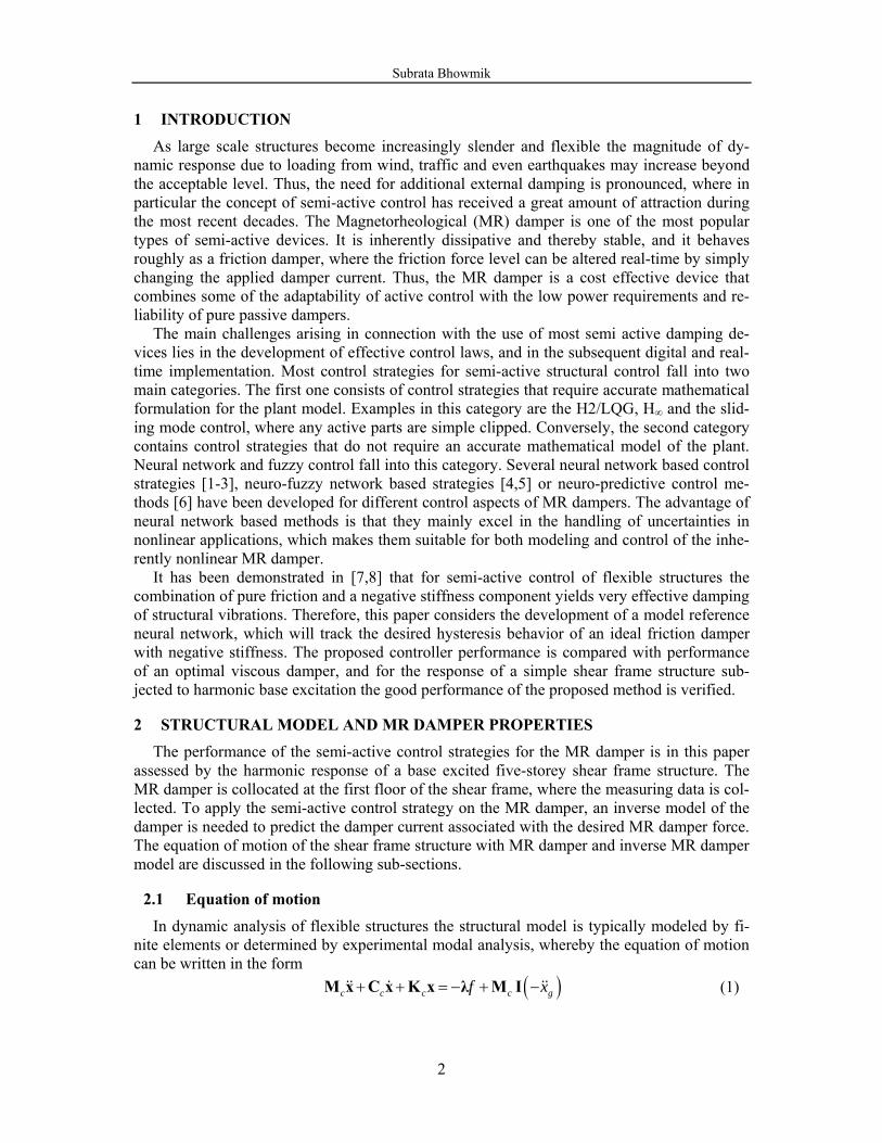
[1,0,0,0,0]T=λ is the connectivity vector that applies the semi-active force f to the first mass, T]1,1,1,1,1[=I is the unity vector and gx is the ground acceleration. The schematic illu-stration of the shear frame structure with rotational MR damper is shown in Fig. 1.
+ +
Mass 1
Mass 5
Base
x5
x1
xg....
MR Damper
Figure 1: Shear Frame Structure with MR damper
2.2 MR damper model
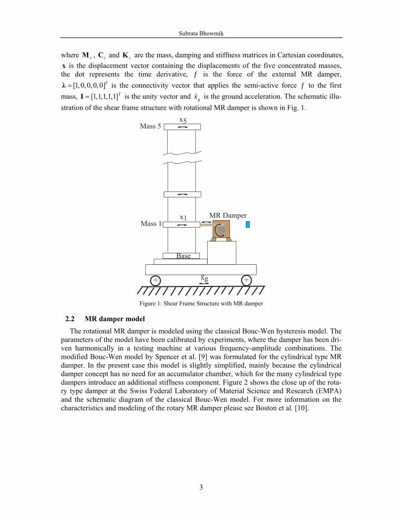
The rotational MR damper is modeled using the classical Bouc-Wen hysteresis model. The parameters of the model have been calibrated by experiments, where the damper has been dri-ven harmonically in a testing machine at various frequency-amplitude combinations. The modified Bouc-Wen model by Spencer et al. [9] was formulated for the cylindrical type MR damper. In the present case this model is slightly simplified, mainly because the cylindrical damper concept has no need for an accumulator chamber, which for the many cylindrical type dampers introduce an additional stiffness component. Figure 2 shows the close up of the rota-ry type damper at the Swiss Federal Laboratory of Material Science and Research (EMPA) and the schematic diagram of the classical Bouc-Wen model. For more information on the characteristics and modeling of the rotary MR damper please see Boston et al. [10].
Subrata Bhowmik
4
Metallic Housing
MR Fluid inside
Rotational Disc inside
Bouc-Wen
Co
x
F
Figure 2: Rotational MR Damper and Bouc-Wen damper model
The governing equations for the damper force f predicted by the classical Bouc-Wen model can be written as follows:
( )0f z c xα= + (2)
where the hysteresis effect follows from the evolutionary variable z controlled by the Bouc-Wen equation 1 ( ) ( )n nz x z z x z A xγ β−= − − + (3)
The gain parameters on the hysteresis effect and the viscous effect are in the present case de-scribed by cubic and linear functions of the applied current, respectively: 2 3
0 0 0,a b c d a bu u u c c c uα α α α α= + + + = + (4)
The applied current u is described with a time delay relative to the desired current I by the fol-lowing first order filter:
( )u u iη= − − (5)
The estimated parameters of the simplified Bouc-Wen model for the rotational MR damper are given in Table. 1.
MR Damper Parameters aα 4.038 η 100
bα 1.984 γ 410
cα 7.901 β 410
dα -0.704 A 1000
0ac 10 0bc 100
Table 1: Parameters for Bouc-Wen Model
Subrata Bhowmik
5
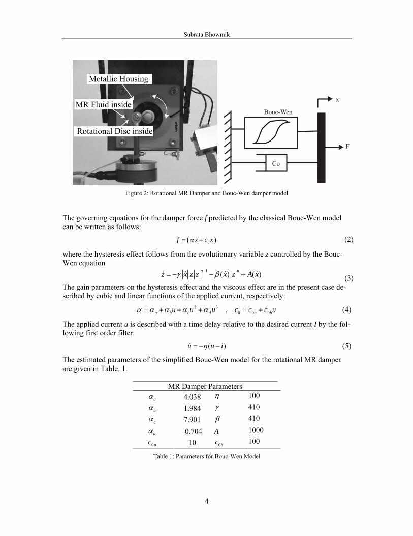
Typical force-displacement and force-velocity hysteresis loops for the rotational MR damper are shown in Fig. 3. It is seen that the MR damper behaves approximately as a friction damper, where the friction force level can be altered by changing the applied damper current. The opening of the force-velocity loops indicates some form of stiffness or inertia effects.
−0.015 −0.01 −0.005 0 0.005 0.01 0.015−400−300−200−100
0100200300400
Displacement, m
Forc
e, N
0 V1 V2 V3 V4 V
−0.2 −0.15−0.1 −0.05 0 0.05 0.1 0.15 0.2−400−300−200−100
0100200300400
Velocity, m/s
Forc
e, N
0 V1 V2 V3 V4 V
Figure 3: Force Displacement /Velocity hysteresis loops.
2.3 Inverse MR damper
The inverse model modeling for rotary MR damper is a quite complicated task due to high nonlinearity in MR damper dynamics. This work can be done by using parametric [10] such as Evolutionary Algorithm and also non-parametric system identification methods such as neural network identification approach [11, 12]. The inverse MR damper behavior is modeled to solve the force tracking task by MR damper in closed loop cycle. The training and valida-tion data are generated by dynamic tests of the MR damper mounted on a hydraulic testing machine. The inverse modeling training data are absolute velocity and absolute force and the current is the target. This approach has been chosen because current is always positive and thereby leads to a small modeling error independently of the sign of velocity. The inverse model of the MR damper is verified with totally independent set of input-output data. The model validation is thoroughly described in Bhowmik et al [14].
The inverse MR damper behaviour, i.e. the input states at time instant k are the damper velocity 1( )x k and desired control force )(kfdes and the output state is current )(kI , is mod-elled by a neural network with the following architecture
1 1 1 1( ) ( 1) ( 2) ( 3)( )
( ) ( 1) ( 2) ( 3)des des des des
x k x k x k x kI k NN
f k f k f k f k⎡ ⎤− − −
= ⎢ ⎥− − −⎣ ⎦ (6)
The neural network based inverse MR damper model is used to solve the force tracking task.
3 CONTROL STRATEGIES The present paper describes a neural network based model reference control strategy for
the prediction of the desired force to control structural vibrations. To evaluate the perfor-mance of the proposed model reference controller, the optimal pure viscous damper force is also applied to the structure.
Subrata Bhowmik
6
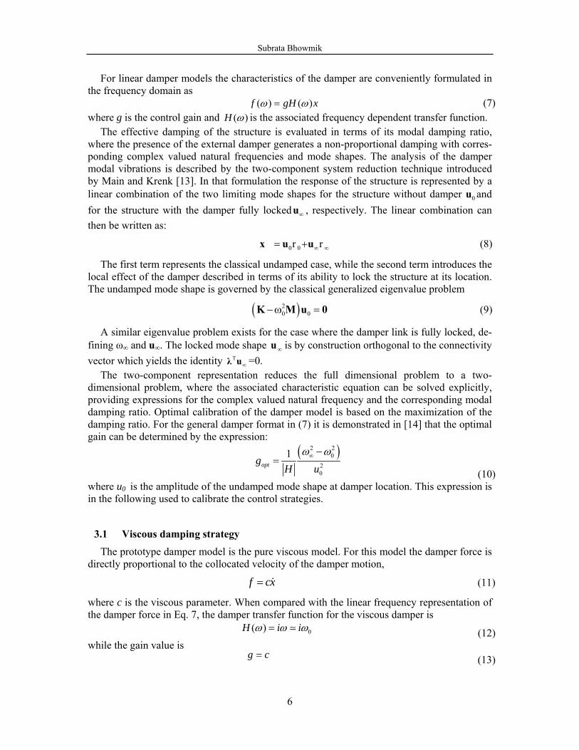
For linear damper models the characteristics of the damper are conveniently formulated in the frequency domain as
( ) ( )f gH xω ω= (7) where g is the control gain and ( )H ω is the associated frequency dependent transfer function.
The effective damping of the structure is evaluated in terms of its modal damping ratio, where the presence of the external damper generates a non-proportional damping with corres-ponding complex valued natural frequencies and mode shapes. The analysis of the damper modal vibrations is described by the two-component system reduction technique introduced by Main and Krenk [13]. In that formulation the response of the structure is represented by a linear combination of the two limiting mode shapes for the structure without damper 0u and for the structure with the damper fully locked ∞u , respectively. The linear combination can then be written as:
0 0 r r ∞ ∞= +x u u (8)
The first term represents the classical undamped case, while the second term introduces the local effect of the damper described in terms of its ability to lock the structure at its location. The undamped mode shape is governed by the classical generalized eigenvalue problem
( )20 0−ω =K M u 0 (9)
A similar eigenvalue problem exists for the case where the damper link is fully locked, de-fining ω∞ and u∞. The locked mode shape ∞u is by construction orthogonal to the connectivity vector which yields the identity T
∞λ u =0. The two-component representation reduces the full dimensional problem to a two-
dimensional problem, where the associated characteristic equation can be solved explicitly, providing expressions for the complex valued natural frequency and the corresponding modal damping ratio. Optimal calibration of the damper model is based on the maximization of the damping ratio. For the general damper format in (7) it is demonstrated in [14] that the optimal gain can be determined by the expression:
( )2 2
020
1optg
H uω ω∞ −=
(10) where u0 is the amplitude of the undamped mode shape at damper location. This expression is in the following used to calibrate the control strategies.
3.1 Viscous damping strategy The prototype damper model is the pure viscous model. For this model the damper force is
directly proportional to the collocated velocity of the damper motion,
f cx= (11)
where c is the viscous parameter. When compared with the linear frequency representation of the damper force in Eq. 7, the damper transfer function for the viscous damper is
0( )H i iω ω ω= (12)
while the gain value is g c= (13)
Subrata Bhowmik
7
Substitution of (12) and (13) into (10) gives the following expression for the optimal viscous parameter:
( )020
2optc
uω ω∞ −≈
(14)
where 0 02ω ω ω∞ + ≈ The optimal viscous damper is without stiffness and is therefore a suitable benchmark ex-
ample for damper models with negative stiffness.
3.2 Proposed Neural network based model reference control strategy
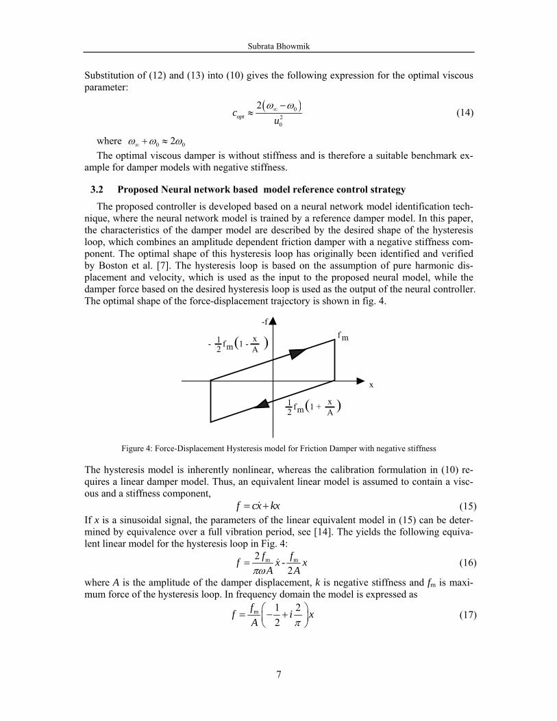
The proposed controller is developed based on a neural network model identification tech-nique, where the neural network model is trained by a reference damper model. In this paper, the characteristics of the damper model are described by the desired shape of the hysteresis loop, which combines an amplitude dependent friction damper with a negative stiffness com-ponent. The optimal shape of this hysteresis loop has originally been identified and verified by Boston et al. [7]. The hysteresis loop is based on the assumption of pure harmonic dis-placement and velocity, which is used as the input to the proposed neural model, while the damper force based on the desired hysteresis loop is used as the output of the neural controller. The optimal shape of the force-displacement trajectory is shown in fig. 4.
x
-ff m1
2 (1 - )mf xA-
12 (1 + )mf x
A
Figure 4: Force-Displacement Hysteresis model for Friction Damper with negative stiffness
The hysteresis model is inherently nonlinear, whereas the calibration formulation in (10) re-quires a linear damper model. Thus, an equivalent linear model is assumed to contain a visc-ous and a stiffness component,
f cx kx= + (15) If x is a sinusoidal signal, the parameters of the linear equivalent model in (15) can be deter-mined by equivalence over a full vibration period, see [14]. The yields the following equiva-lent linear model for the hysteresis loop in Fig. 4:
m m2 -2
f ff x xA Aπω
= (16)
where A is the amplitude of the damper displacement, k is negative stiffness and fm is maxi-mum force of the hysteresis loop. In frequency domain the model is expressed as
m 1 22
ff i xA π⎛ ⎞= − +⎜ ⎟⎝ ⎠
(17)
Subrata Bhowmik
8
Comparison with the frequency representation in Eq. 7 gives the following expression for the transfer function of the linear equivalent hysteretic damper model:
1 2( )2
H iωπ
⎛ ⎞= − +⎜ ⎟⎝ ⎠ (18)
and the corresponding gain value:
g =mfA (19)
From Eq.10 the optimal value of g is determined as
( )2 20
20
1.24optgu
ω ω∞ −= (20)
The optimal value fm is determined as
m optf g A=
(21) where A is the amplitude of the displacement.
In this paper, a four-layer feed forward neural network is adopted which consists of one in-put, two hidden layers and a single output layer. The displacement and velocity with current state and five preceding values are taken as input and force at current state is output in the proposed neural network. The neural network controller is trained with training data generated at different amplitudes and at different frequencies of both the displacement response and the corresponding force data from the optimal friction model. The trained model is verified with independent data set and subsequently used in a closed loop implementation. The training al-gorithm used in the feed forward back propagation neural network is the Levenberg-Marquardt (LM) algorithm based on a least-square curve fitting.
4 NUMERICAL EXAMPLES
To evaluate the effectiveness of the proposed control strategy for the structural vibration mitigation with rotary MR damper, two numerical examples are considered. The first one is based on pure viscous damping strategy and the second one is our proposed neural network based model reference control (NN-MRC). Both the examples are discussed below
4.1 Viscous Damper
The viscous damping strategy using MR damper in closed loop is simulated for five storied shear frame structure with harmonic base excitation. The force-velocity and force-displacement hysteresis plots of the damper force and desired force from control law are compared for optimal viscous damping strategy and the result is quite satisfactory. The force tracking task by MR damper is quite well. From fig. 3, it is visible that MR damper has a force limit at zero current. For that reason it is not possible for MR damper to follow the de-sired force below the force limit at zero current. Here for this damper, force limit is 24 N.
Subrata Bhowmik
9
−5 0 5 x 10⁻³
−50
0
50A
ctua
l For
ce, N
−0.05 0 0.05
−50
0
50
−5 0 5 x 10⁻³
−50
0
50
Damper Displacement, m
Des
ired
Forc
e, N
−0.05 0 0.05
−50
0
50
Damper Velocity, m/s
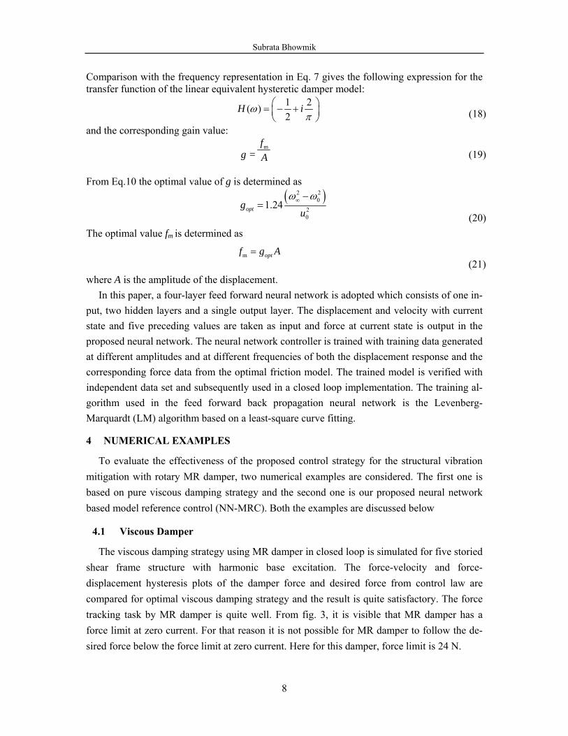
Figure 5: Force-Displacement and Force Velocity hysteresis diagram for viscous damper
The top floor displacement and damper displacement are shown in fig. 6.
4 4.5 5 5.5 6 6.5 7 7.5 8−8−6−4−202468 x 10−3
Time, S
Dam
per D
ispl
acem
ent,
m
4 4.5 5 5.5 6 6.5 7 7.5 8−0.04−0.03−0.02−0.01
00.010.020.030.04
Time, S
Top
Floo
r Dis
p, m
Figure 6: Time history of damper and top floor displacement for viscous damper
The viscous damping strategy is also applied directly on structure without MR damper and compared the change in performance.
Subrata Bhowmik
10
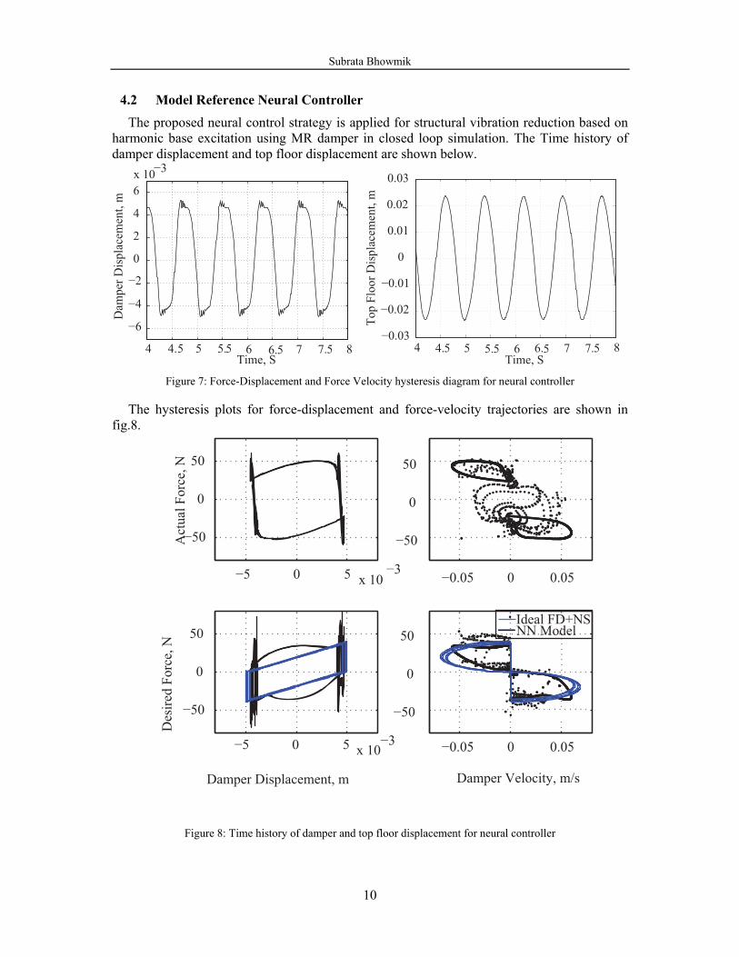
4.2 Model Reference Neural Controller
The proposed neural control strategy is applied for structural vibration reduction based on harmonic base excitation using MR damper in closed loop simulation. The Time history of damper displacement and top floor displacement are shown below.
4 4.5 5 5.5 6 6.5 7 7.5 8
−6
−4
−2
0
2
4
6x 10⁻³
Time, S
Dam
per D
ispl
acem
ent,
m
4 4.5 5 5.5 6 6.5 7 7.5 8
−0.03
−0.02
−0.01
0
0.01
0.02
0.03
Time, STo
p Fl
oor D
ispl
acem
ent,
m
Figure 7: Force-Displacement and Force Velocity hysteresis diagram for neural controller
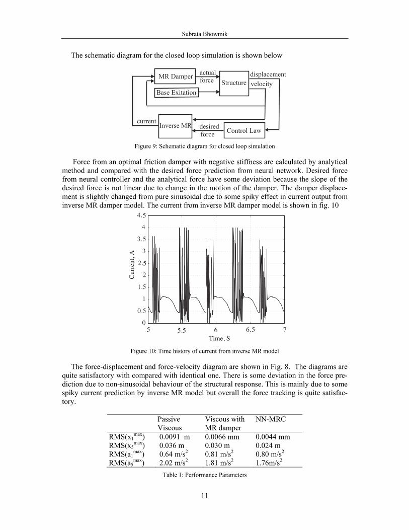
The hysteresis plots for force-displacement and force-velocity trajectories are shown in fig.8.
−5 0 5 x 10⁻³
−50
0
50
Act
ual F
orce
, N
−0.05 0 0.05
−50
0
50
−5 0 5 x 10⁻³
−50
0
50
Damper Displacement, m
Des
ired
Forc
e, N
−0.05 0 0.05
−50
0
50
Damper Velocity, m/s
Ideal FD+NSNN Model
Figure 8: Time history of damper and top floor displacement for neural controller
Subrata Bhowmik
11
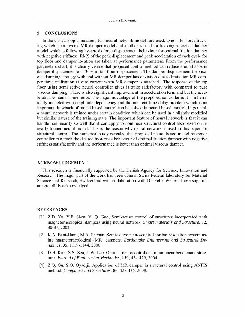
The schematic diagram for the closed loop simulation is shown below
StructureBase Exitation
MR Damper displacement
Inverse MR
velocity
Control Lawforcedesired
forceactual
current
Figure 9: Schematic diagram for closed loop simulation
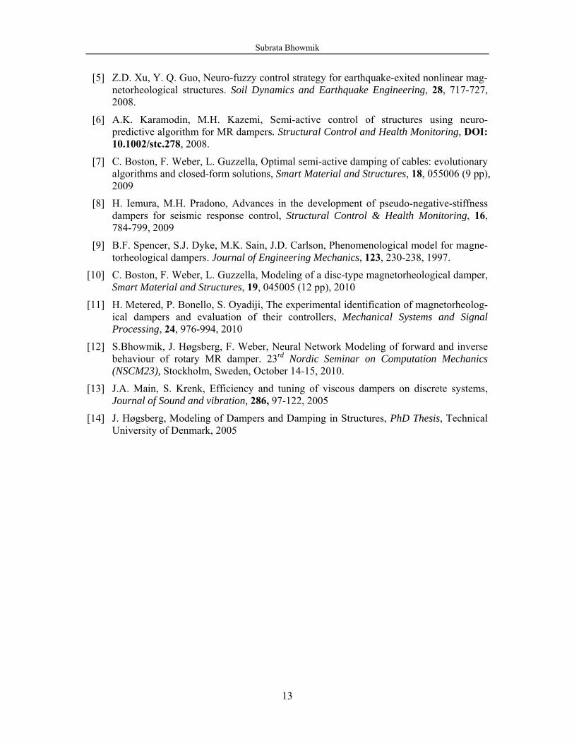
Force from an optimal friction damper with negative stiffness are calculated by analytical method and compared with the desired force prediction from neural network. Desired force from neural controller and the analytical force have some deviation because the slope of the desired force is not linear due to change in the motion of the damper. The damper displace-ment is slightly changed from pure sinusoidal due to some spiky effect in current output from inverse MR damper model. The current from inverse MR damper model is shown in fig. 10
5 5.5 6 6.5 70
0.5
1
1.5
2
2.5
3
3.5
4
4.5
Time, S
Cur
rent
, A
Figure 10: Time history of current from inverse MR model
The force-displacement and force-velocity diagram are shown in Fig. 8. The diagrams are quite satisfactory with compared with identical one. There is some deviation in the force pre-diction due to non-sinusoidal behaviour of the structural response. This is mainly due to some spiky current prediction by inverse MR model but overall the force tracking is quite satisfac-tory.
Passive Viscous
Viscous with MR damper
NN-MRC
RMS(x1max) 0.0091 m 0.0066 mm 0.0044 mm
RMS(x5max) 0.036 m 0.030 m 0.024 m
RMS(a1max) 0.64 m/s2 0.81 m/s2 0.80 m/s2
RMS(a5max) 2.02 m/s2 1.81 m/s2 1.76m/s2
Table 1: Performance Parameters
Subrata Bhowmik
12
5 CONCLUSIONS
In the closed loop simulation, two neural network models are used. One is for force track-ing which is an inverse MR damper model and another is used for tracking reference damper model which is following hysteresis force-displacement behaviour for optimal friction damper with negative stiffness. RMS of the peak displacement and peak acceleration of each cycle for top floor and damper location are taken as performance parameters. From the performance parameters chart, it is clearly visible that proposed control method can reduce around 35% in damper displacement and 30% in top floor displacement. The damper displacement for visc-ous damping strategy with and without MR damper has deviation due to limitation MR dam-per force realization at zero current when MR damper is attached. The response of the top floor using semi active neural controller gives is quite satisfactory with compared to pure viscous damping. There is also significant improvement in acceleration term and but the acce-leration contains some noise. The major advantage of the proposed controller is it is inherri-tently modeled with amplitude dependency and the inherent time-delay problem which is an important drawback of model based control can be solved in neural based control. In general, a neural network is trained under certain condition which can be used in a slightly modified but similar nature of the training state. The important feature of neural network is that it can handle nonlinearity so well that it can apply to nonlinear structural control also based on li-nearly trained neural model. This is the reason why neural network is used in this paper for structural control. The numerical study revealed that proposed neural based model reference controller can track the desired hysteresis behaviour of optimal friction damper with negative stiffness satisfactorily and the performance is better than optimal viscous damper.
ACKNOWLEDGEMENT This research is financially supported by the Danish Agency for Science, Innovation and
Research. The major part of the work has been done at Swiss Federal laboratory for Material Science and Research, Switzerland with collaboration with Dr. Felix Weber. These supports are gratefully acknowledged.
REFERENCES [1] Z.D. Xu, Y.P. Shen, Y. Q. Guo, Semi-active control of structures incorporated with
magnetorheological dampers using neural network. Smart materials and Structure, 12, 80-87, 2003.
[2] K.A. Bani-Hami, M.A. Sheban, Semi-active neuro-control for base-isolation system us-ing magnetorheological (MR) dampers. Earthquake Engineering and Structural Dy-namics, 35, 1119-1144, 2006.
[3] D.H. Kim, S.N. Seo, I. W. Lee, Optimal neurocontroller for nonlinear benchmark struc-ture. Journal of Engineering Mechanics, 130, 424-429, 2004.
[4] Z.Q. Gu, S.O. Oyadiji, Application of MR damper in structural control using ANFIS method. Computers and Structures, 86, 427-436, 2008.
Subrata Bhowmik
13
[5] Z.D. Xu, Y. Q. Guo, Neuro-fuzzy control strategy for earthquake-exited nonlinear mag-netorheological structures. Soil Dynamics and Earthquake Engineering, 28, 717-727, 2008.
[6] A.K. Karamodin, M.H. Kazemi, Semi-active control of structures using neuro-predictive algorithm for MR dampers. Structural Control and Health Monitoring, DOI: 10.1002/stc.278, 2008.
[7] C. Boston, F. Weber, L. Guzzella, Optimal semi-active damping of cables: evolutionary algorithms and closed-form solutions, Smart Material and Structures, 18, 055006 (9 pp), 2009
[8] H. Iemura, M.H. Pradono, Advances in the development of pseudo-negative-stiffness dampers for seismic response control, Structural Control & Health Monitoring, 16, 784-799, 2009
[9] B.F. Spencer, S.J. Dyke, M.K. Sain, J.D. Carlson, Phenomenological model for magne-torheological dampers. Journal of Engineering Mechanics, 123, 230-238, 1997.
[10] C. Boston, F. Weber, L. Guzzella, Modeling of a disc-type magnetorheological damper, Smart Material and Structures, 19, 045005 (12 pp), 2010
[11] H. Metered, P. Bonello, S. Oyadiji, The experimental identification of magnetorheolog-ical dampers and evaluation of their controllers, Mechanical Systems and Signal Processing, 24, 976-994, 2010
[12] S.Bhowmik, J. Høgsberg, F. Weber, Neural Network Modeling of forward and inverse behaviour of rotary MR damper. 23rd Nordic Seminar on Computation Mechanics (NSCM23), Stockholm, Sweden, October 14-15, 2010.
[13] J.A. Main, S. Krenk, Efficiency and tuning of viscous dampers on discrete systems, Journal of Sound and vibration, 286, 97-122, 2005
[14] J. Høgsberg, Modeling of Dampers and Damping in Structures, PhD Thesis, Technical University of Denmark, 2005


![arXiv:1811.03760v1 [cs.LG] 9 Nov 2018 · parameters, an evolutionary attention learning ap-proach is introduced to the LSTMs model. Thus, like that for biological evolution, the pattern](https://static.fdocument.org/doc/165x107/5e04b4063338cd58f63d83c7/arxiv181103760v1-cslg-9-nov-2018-parameters-an-evolutionary-attention-learning.jpg)