Module W.bas - cs.sjtu.edu.cn
27
1 Wireless Network Basics Module W.bas.2 Dr.M.Y.Wu@CSE Shanghai Jiaotong University Shanghai, China Dr.W.Shu@ECE University of New Mexico Albuquerque, NM, USA
Transcript of Module W.bas - cs.sjtu.edu.cn
1
Wireless Network BasicsModule W.bas.2
Dr.M.Y.Wu@CSEShanghai Jiaotong University
Shanghai, China
Dr.W.Shu@ECEUniversity of New Mexico
Albuquerque, NM, USA
© by Dr.Wu@SJTU & Dr.Shu@UNM
W.bas.2-2
Wireless network basics
Frequency spectrumTransmission mediaRadio wavesSpectrum regulation
Radio channel basicsRadio propagation
Channel characteristics
End of W.bas.2
© by Dr.Wu@SJTU & Dr.Shu@UNM
W.bas.2-3
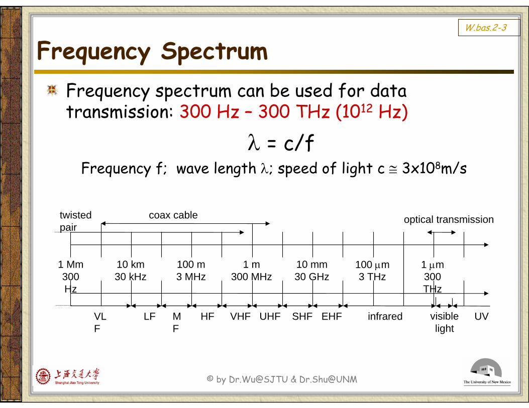
Frequency SpectrumFrequency spectrum can be used for data transmission: 300 Hz – 300 THz (1012 Hz)
λ = c/f Frequency f; wave length λ; speed of light c ≅ 3x10⁸m/s
1 Mm300 Hz
10 km30 kHz
100 m3 MHz
1 m300 MHz
10 mm30 GHz
100 μm3 THz
1 μm300 THz
visible light
VLF
LF MF
HF VHF UHF SHF EHF infrared UV
optical transmissioncoax cabletwisted pair
© by Dr.Wu@SJTU & Dr.Shu@UNM
W.bas.2-4
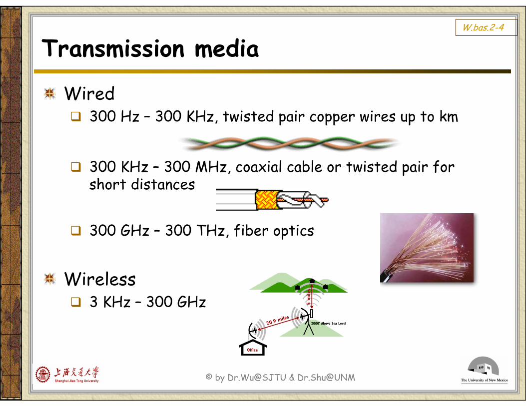
Transmission media
Wired300 Hz – 300 KHz, twisted pair copper wires up to km
300 KHz – 300 MHz, coaxial cable or twisted pair for short distances
300 GHz – 300 THz, fiber optics
Wireless3 KHz – 300 GHz
© by Dr.Wu@SJTU & Dr.Shu@UNM
W.bas.2-5
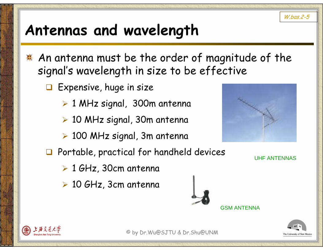
Antennas and wavelength
An antenna must be the order of magnitude of the signal’s wavelength in size to be effective
Expensive, huge in size
1 MHz signal, 300m antenna
10 MHz signal, 30m antenna
100 MHz signal, 3m antenna
Portable, practical for handheld devices
1 GHz, 30cm antenna
10 GHz, 3cm antenna
UHF ANTENNAS
GSM ANTENNA
© by Dr.Wu@SJTU & Dr.Shu@UNM
W.bas.2-6
Radio wavesGeneral characteristics
Easy to generate, both indoor & outdoor useAble to pass through buildings & travel long distancesIts transmission is omni-directional, no need to physically align the transmitter & receiverFor lower frequency
Waves can pass through obstacles easilyPower falls with 1/d2, d is distance
For higher frequencyReflected by obstaclesMore prone to absorption by rain drops
© by Dr.Wu@SJTU & Dr.Shu@UNM
W.bas.2-7
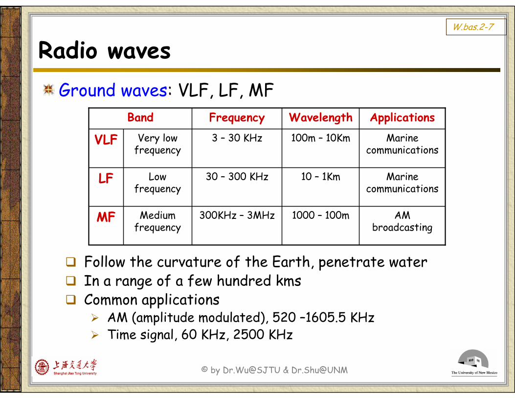
Radio wavesGround waves: VLF, LF, MF
Follow the curvature of the Earth, penetrate waterIn a range of a few hundred kmsCommon applications
AM (amplitude modulated), 520 –1605.5 KHzTime signal, 60 KHz, 2500 KHz
ApplicationsWavelengthFrequencyBand
AM broadcasting
1000 – 100m300KHz – 3MHz Medium frequency
MF
Marine communications
10 – 1Km30 – 300 KHzLow frequency
LF
Marine communications
100m – 10Km3 – 30 KHzVery low frequency
VLF
© by Dr.Wu@SJTU & Dr.Shu@UNM
W.bas.2-8
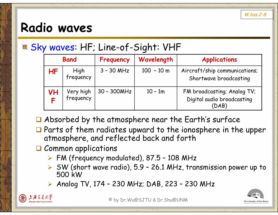
Radio wavesSky waves: HF; Line-of-Sight: VHF
Absorbed by the atmosphere near the Earth’s surfaceParts of them radiates upward to the ionosphere in the upper atmosphere, and reflected back and forthCommon applications
FM (frequency modulated), 87.5 – 108 MHzSW (short wave radio), 5.9 – 26.1 MHz, transmission power up to 500 kWAnalog TV, 174 – 230 MHz; DAB, 223 – 230 MHz
ApplicationsWavelengthFrequencyBand
FM broadcasting; Analog TV;Digital audio broadcasting
(DAB)
10 – 1m30 – 300MHz Very high frequency
VHF
Aircraft/ship communications; Shortwave broadcasting
100 – 10 m3 – 30 MHzHigh frequency
HF
© by Dr.Wu@SJTU & Dr.Shu@UNM
W.bas.2-9
MicrowavesGeneral characteristics
Tend to travel in straight linesCan be narrowly focused, energy is concentrated into a small beam with higher SNR (signal-to-noise-ratio)Used for mobile phone & TV transmissionUsed for long-distance telephony, before replaced by fiber optics
Due to higher frequencyDo not pass through buildingsRequire LOS (line-of-sight) alignment between the transmitting and receiving antennasNeed repeaters
© by Dr.Wu@SJTU & Dr.Shu@UNM
W.bas.2-10
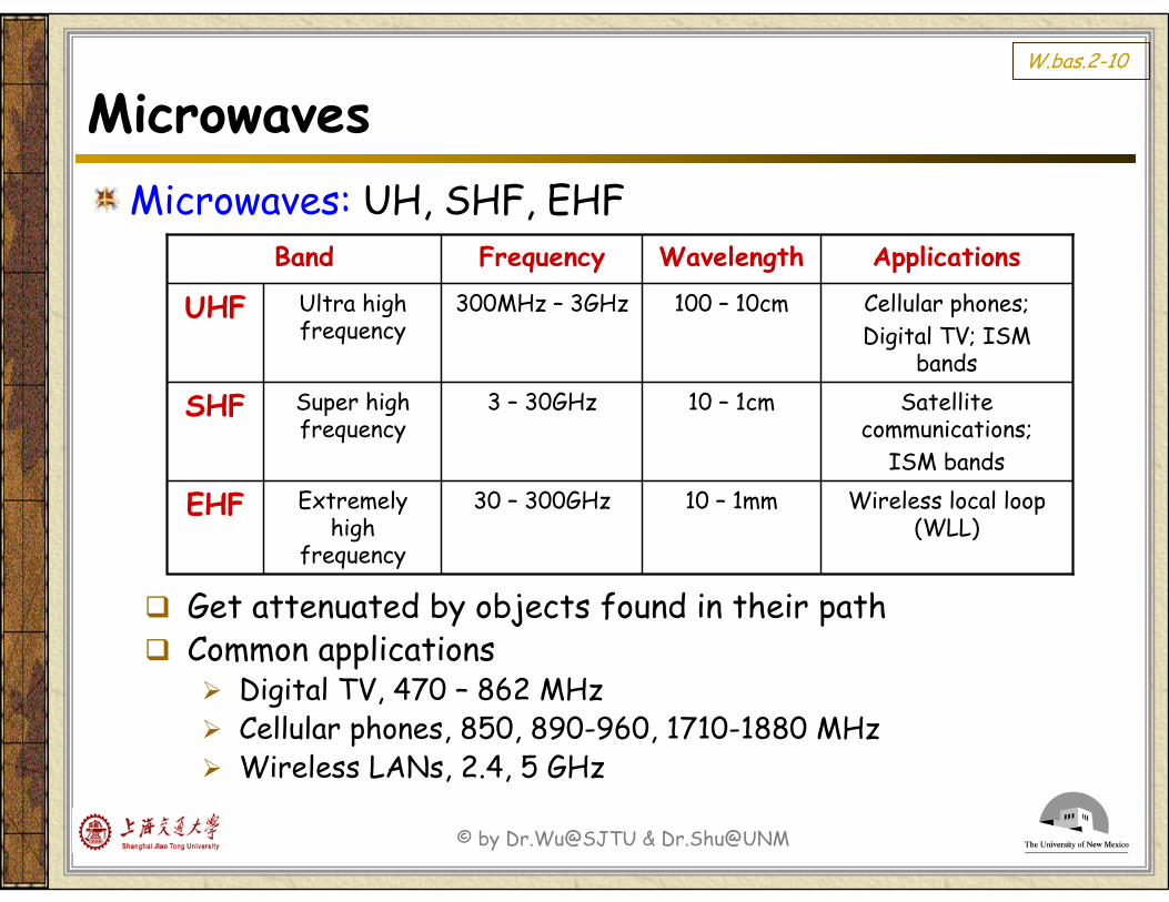
MicrowavesMicrowaves: UH, SHF, EHF
Get attenuated by objects found in their pathCommon applications
Digital TV, 470 – 862 MHzCellular phones, 850, 890-960, 1710-1880 MHz Wireless LANs, 2.4, 5 GHz
ApplicationsWavelengthFrequencyBand
Wireless local loop (WLL)
10 – 1mm30 – 300GHz Extremely high
frequency
EHF
Satellite communications;
ISM bands
10 – 1cm3 – 30GHzSuper high frequency
SHF
Cellular phones;Digital TV; ISM
bands
100 – 10cm300MHz – 3GHzUltra high frequency
UHF
© by Dr.Wu@SJTU & Dr.Shu@UNM
W.bas.2-11
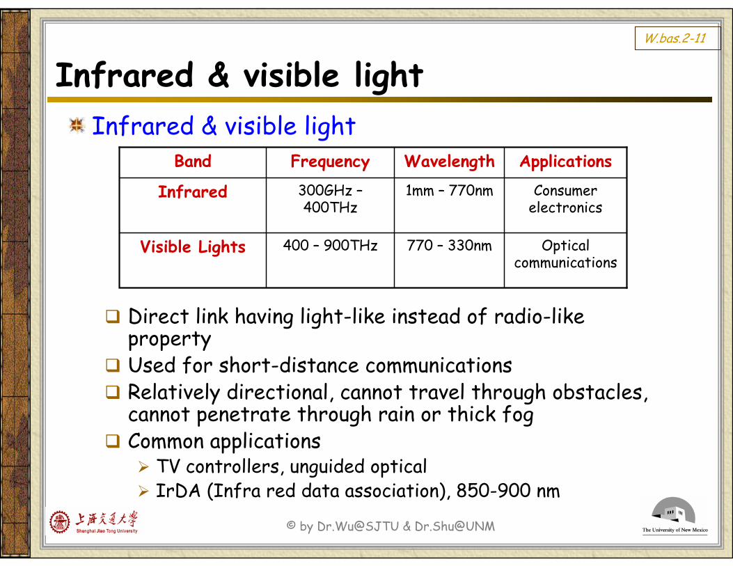
Infrared & visible lightInfrared & visible light
Direct link having light-like instead of radio-like propertyUsed for short-distance communicationsRelatively directional, cannot travel through obstacles, cannot penetrate through rain or thick fogCommon applications
TV controllers, unguided opticalIrDA (Infra red data association), 850-900 nm
ApplicationsWavelengthFrequencyBand
Optical communications
770 – 330nm400 – 900THzVisible Lights
Consumer electronics
1mm – 770nm300GHz –400THz
Infrared
© by Dr.Wu@SJTU & Dr.Shu@UNM
W.bas.2-12
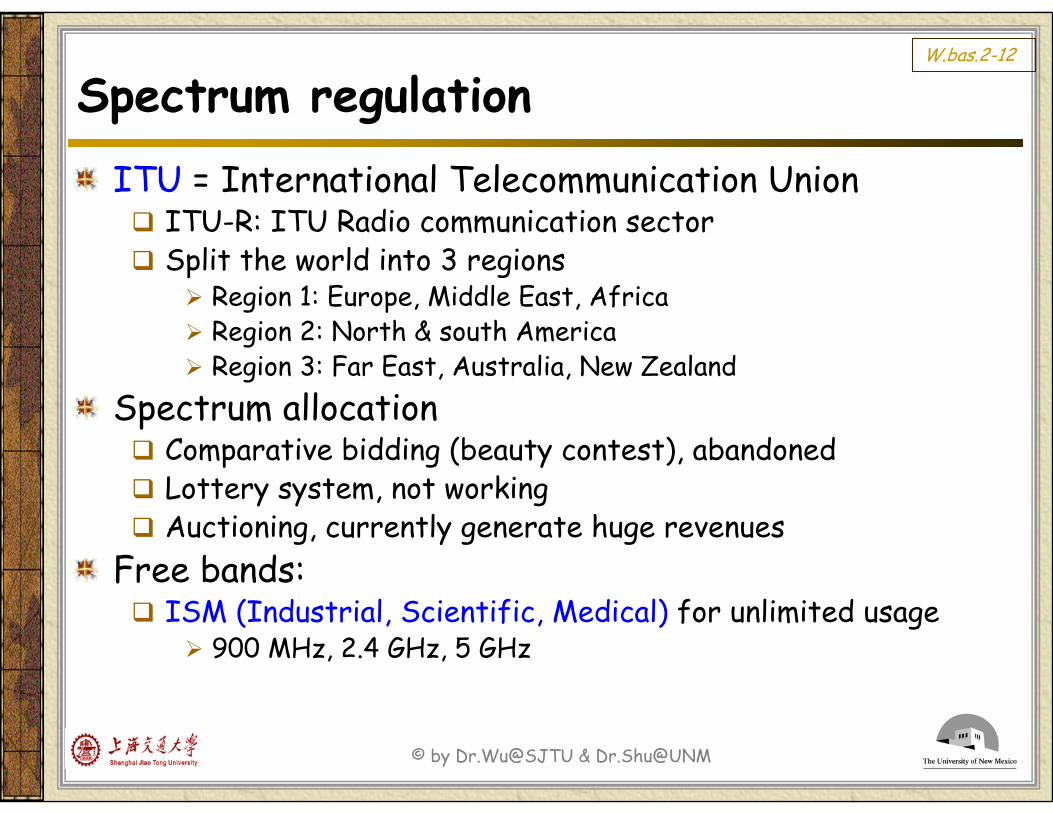
Spectrum regulationITU = International Telecommunication Union
ITU-R: ITU Radio communication sectorSplit the world into 3 regions
Region 1: Europe, Middle East, AfricaRegion 2: North & south AmericaRegion 3: Far East, Australia, New Zealand
Spectrum allocationComparative bidding (beauty contest), abandonedLottery system, not workingAuctioning, currently generate huge revenues
Free bands:ISM (Industrial, Scientific, Medical) for unlimited usage
900 MHz, 2.4 GHz, 5 GHz
© by Dr.Wu@SJTU & Dr.Shu@UNM
W.bas.2-13
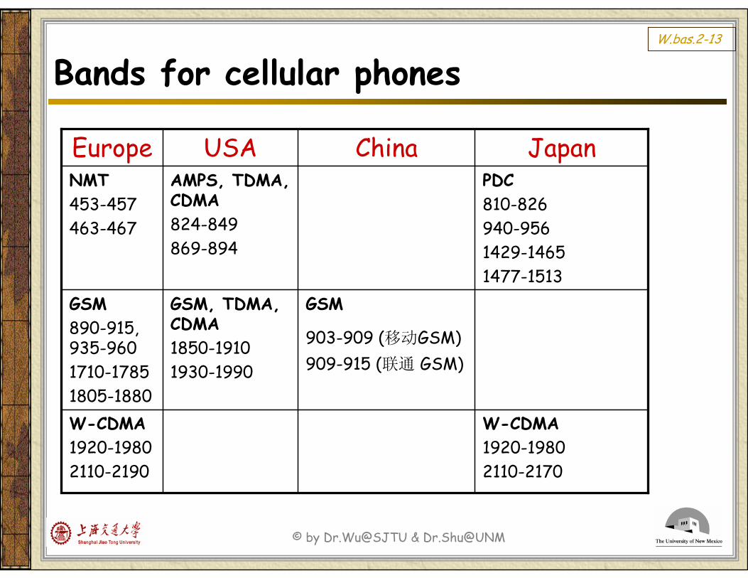
Bands for cellular phones
W-CDMA1920-19802110-2170
W-CDMA1920-19802110-2190
GSM
903-909 (移动GSM)909-915 (联通 GSM)
GSM, TDMA, CDMA1850-19101930-1990
GSM890-915, 935-9601710-17851805-1880
PDC810-826940-9561429-14651477-1513
AMPS, TDMA, CDMA824-849869-894
NMT453-457463-467
JapanChinaUSAEurope
© by Dr.Wu@SJTU & Dr.Shu@UNM
W.bas.2-14
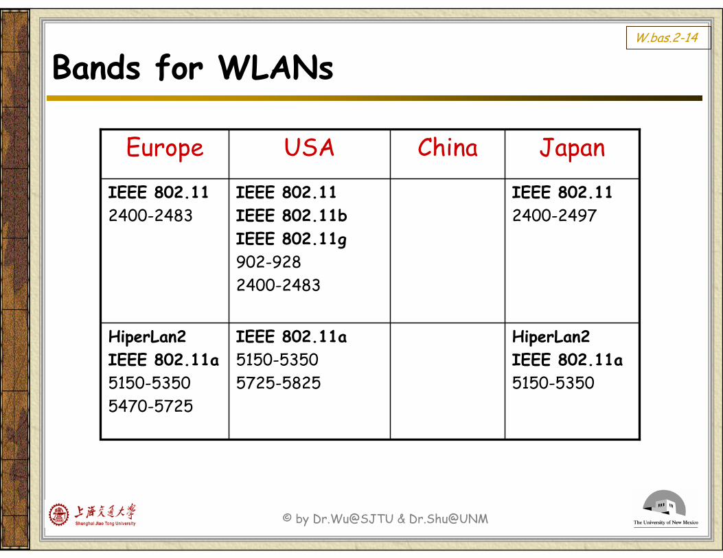
Bands for WLANs
HiperLan2IEEE 802.11a5150-5350
IEEE 802.11a5150-53505725-5825
HiperLan2IEEE 802.11a5150-53505470-5725
IEEE 802.112400-2497
IEEE 802.11IEEE 802.11bIEEE 802.11g902-9282400-2483
IEEE 802.112400-2483
JapanChinaUSAEurope
© by Dr.Wu@SJTU & Dr.Shu@UNM
W.bas.2-15
Wireless network basics
Frequency spectrumTransmission media
Radio waves
Spectrum regulation
Radio channel basicsRadio propagationChannel characteristics
End of W.bas.2
© by Dr.Wu@SJTU & Dr.Shu@UNM
W.bas.2-16
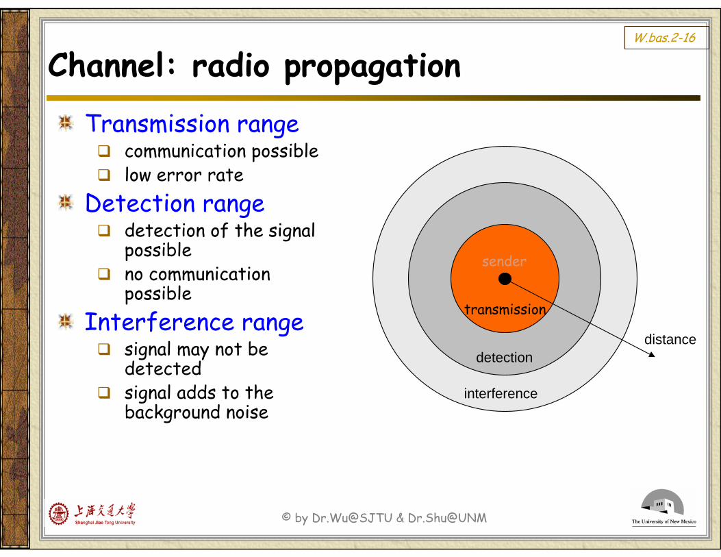
Channel: radio propagationTransmission range
communication possiblelow error rate
Detection rangedetection of the signal possibleno communication possible
Interference rangesignal may not be detected signal adds to the background noise
distance
sender
transmission
detection
interference
© by Dr.Wu@SJTU & Dr.Shu@UNM
W.bas.2-17
Channel: radio propagation
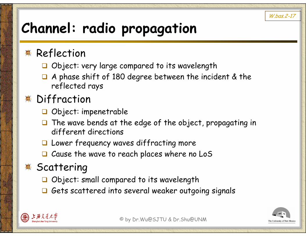
ReflectionObject: very large compared to its wavelengthA phase shift of 180 degree between the incident & the reflected rays
DiffractionObject: impenetrableThe wave bends at the edge of the object, propagating in different directionsLower frequency waves diffracting moreCause the wave to reach places where no LoS
ScatteringObject: small compared to its wavelengthGets scattered into several weaker outgoing signals
© by Dr.Wu@SJTU & Dr.Shu@UNM
W.bas.2-18
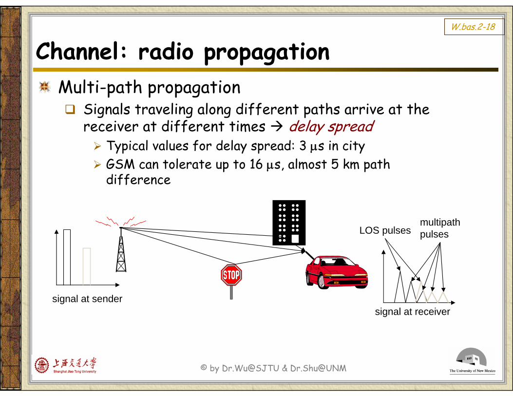
Channel: radio propagationMulti-path propagation
Signals traveling along different paths arrive at the receiver at different times delay spread
Typical values for delay spread: 3 μs in cityGSM can tolerate up to 16 μs, almost 5 km path difference
signal at sendersignal at receiver
LOS pulsesmultipathpulses
© by Dr.Wu@SJTU & Dr.Shu@UNM
W.bas.2-19
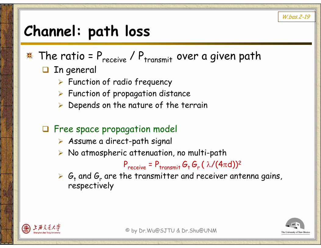
Channel: path lossThe ratio = Preceive / Ptransmit over a given path
In generalFunction of radio frequency Function of propagation distanceDepends on the nature of the terrain
Free space propagation modelAssume a direct-path signalNo atmospheric attenuation, no multi-path
Preceive = Ptransmit Gt Gr ( λ/(4πd))2
Gt and Gr are the transmitter and receiver antenna gains, respectively
© by Dr.Wu@SJTU & Dr.Shu@UNM
W.bas.2-20
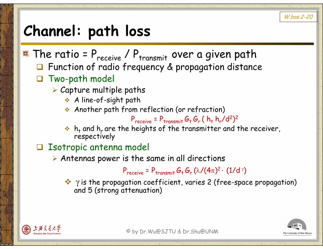
Channel: path lossThe ratio = Preceive / Ptransmit over a given path
Function of radio frequency & propagation distanceTwo-path model
Capture multiple pathsA line-of-sight pathAnother path from reflection (or refraction)
Preceive = Ptransmit Gt Gr ( ht hr/d2)2
ht and hr are the heights of the transmitter and the receiver, respectively
Isotropic antenna modelAntennas power is the same in all directions
Preceive = Ptransmit Gt Gr (λ/(4π)2 ⋅ (1/d γ)γ is the propagation coefficient, varies 2 (free-space propagation) and 5 (strong attenuation)
© by Dr.Wu@SJTU & Dr.Shu@UNM
W.bas.2-21
Channel: fadingFading = the fluctuations in signal strength when received at the receiverTwo types of fading:
Fast fading / small-scale fadingDue to the interference between multiple copies of the same signal arriving at slightly different times (caused by reflection, etc)
Slow fading / large-scale fadingBetween the transmitter and receiver, there exist objects that partially absorb the signal
The receiver is inside a building (the wall acts as an object in between)
© by Dr.Wu@SJTU & Dr.Shu@UNM
W.bas.2-22
Channel: interferenceTwo types of interference:
Adjacent channel interferenceSignals in nearby frequencies have components outside their allocated rangesCan be avoided by introducing guard bands
Co-channel interference (or narrow-band interference)Due to other nearby systems using the same transmission frequency (frequency reuse)Can be reduced with the use of
Multi-user detection (for CDMA)Directional antennasDynamic channel allocation
© by Dr.Wu@SJTU & Dr.Shu@UNM
W.bas.2-23
Channel: mobileDoppler shift = the change/shift in the frequency of the received signal
when the transmitter and the receiver are mobile with respect toeach other
fd = v / λMoving toward each other, the frequency is higherMoving away from each other, the frequency is lower
Limitation of different wireless systemsGSM: < 250km/hAMPS: < 100km/h
Common speed of moving objectsAircraft: 900 km/hTrain: 350 km/hAutomobile: 100 km/h
© by Dr.Wu@SJTU & Dr.Shu@UNM
W.bas.2-24
Channel: rate constraintsTwo important constraints that determine the max rate of data transmission
Nyquist’s theorem in a noiseless channelBaud rate = number of times per second the signal changes its value/voltageBaud rate ≠ bit rate
Since each signal value can convey multiple bitsExample, the voltage values are 0, 1, 2, 3, used to convey two bits (00, 01, 10, 11)
C = 2 · B · log2 L bits/secC: the max channel data rate B: channel bandwidth in Hz (baud rate)L: the number of discrete signal levels used
© by Dr.Wu@SJTU & Dr.Shu@UNM
W.bas.2-25
Channel: rate constraintsTwo important constraints that determine the max rate of data transmission
Shannon’s theorem in a noise channelC = B · log2 (1 + (S/N)) bits/sec
S: signal power N: noise powerC: the max channel data rate B: channel bandwidth in Hz (baud rate)SNR = 10 log10 (S/N), ratio in decibels
© by Dr.Wu@SJTU & Dr.Shu@UNM
W.bas.2-26
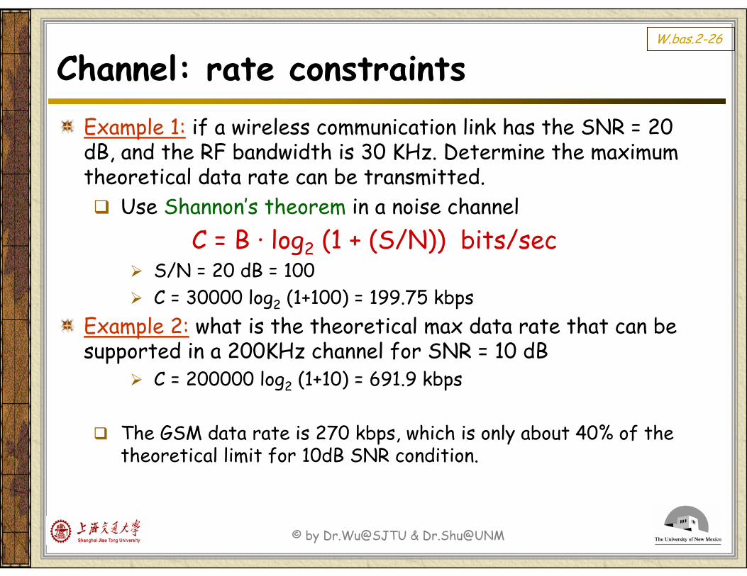
Channel: rate constraintsExample 1: if a wireless communication link has the SNR = 20 dB, and the RF bandwidth is 30 KHz. Determine the maximum theoretical data rate can be transmitted.
Use Shannon’s theorem in a noise channelC = B · log2 (1 + (S/N)) bits/sec
S/N = 20 dB = 100 C = 30000 log2 (1+100) = 199.75 kbps
Example 2: what is the theoretical max data rate that can be supported in a 200KHz channel for SNR = 10 dB
C = 200000 log2 (1+10) = 691.9 kbps
The GSM data rate is 270 kbps, which is only about 40% of the theoretical limit for 10dB SNR condition.
© by Dr.Wu@SJTU & Dr.Shu@UNM
W.bas.2-27
Wireless network basics
Frequency spectrumTransmission media
Radio waves
Spectrum regulation
Radio channel basicsRadio propagation
Channel characteristics
End of W.bas.2