Modern V iew of Light - The Menon Group · PDF fileModern V iew of Light ... whereas in...
74
Modern View of Light Photon = elementary particle Wave-particle duality Energy E = hν h = Planck's constant = 6.626 x 10 -34 J s ν = frequency (1/s) Temporal oscillation frequency of light waves mass = 0 speed c = 3 x 10 8 m/s c = λν Dispersion relation λ = wavelength (m) spatial period of the light waves Momentum p = h/λ
Transcript of Modern V iew of Light - The Menon Group · PDF fileModern V iew of Light ... whereas in...
Modern View of Light
Photon = elementary particle
Wave-particle duality
Energy E = h!
h = Planck's constant
= 6.626 x 10⁻³⁴
J s
! = frequency (1/s)Temporal oscillation frequency of light waves
mass = 0speed c = 3 x 10
8 m/sc = "!
Dispersion relation
" = wavelength (m)spatial period of the light wavesMomentum p = h/"
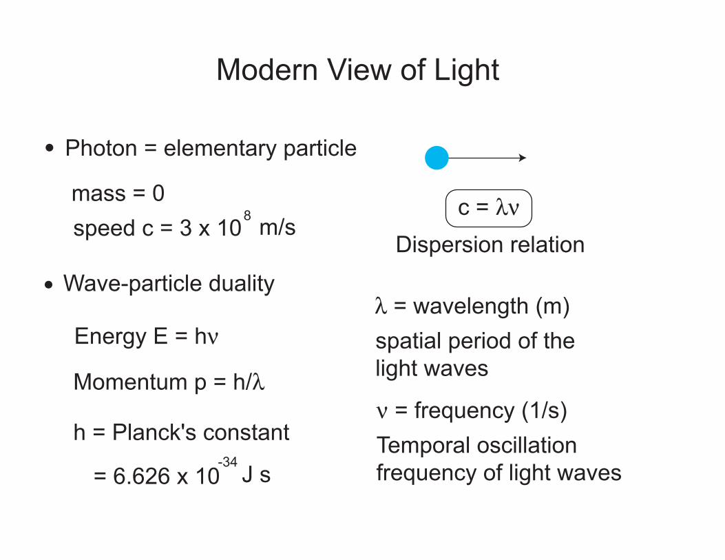
The concept of a "ray"
t=0
wavefronts(planes of constant phase)
"
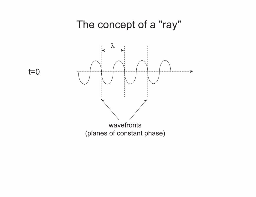
The concept of a "ray"
t = 0
"
t = #t
direction of energyflow = ray
In homogeneous media, light propagates in rectilinear paths

Light in matter
vacuum matter
Speed c = 3 x 10⁸ m/s v = c / n
n = index of refracton (or refractive index)
Absorption Coefficient 0 $energy transmitted through length L = exp(-2$L)
Example: Glass has n ~ 1.5, glass fiber has $ ~ 0.0288 /km
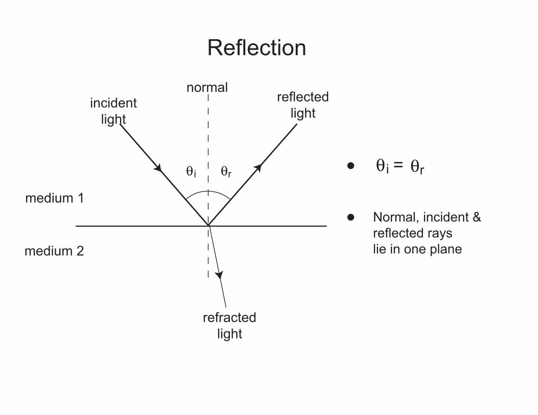
Reflection
medium 1
medium 2
incidentlight
reflectedlight
normal
refractedlight
% i %r % i = %r
Normal, incident & reflected rays lie in one plane

Refraction
medium 1
medium 2
incidentlight
reflectedlight
normal
refractedlight
% i
%t
Incident, reflected & refracted rays lie in one plane
n1
n2
n1sin % i n2sin %t=Snell's Law
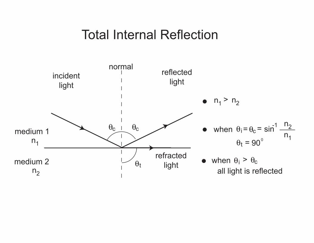
Total Internal Reflection
medium 1
medium 2
incidentlight
reflectedlight
normal
refractedlight
%c
%t
n1
n2
%c
n1 > n2
% iwhen = %c sin-1n2n1
=
%t = 900
when % i > %call light is reflected
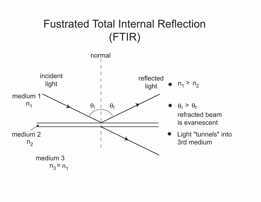
Fustrated Total Internal Reflection(FTIR)
medium 1
medium 2
incidentlight
reflectedlight
normal
% in1
n2
%r
n1 > n2
% i > %c
medium 3n3 = n1
refracted beam is evanescent
Light "tunnels" into 3rd medium
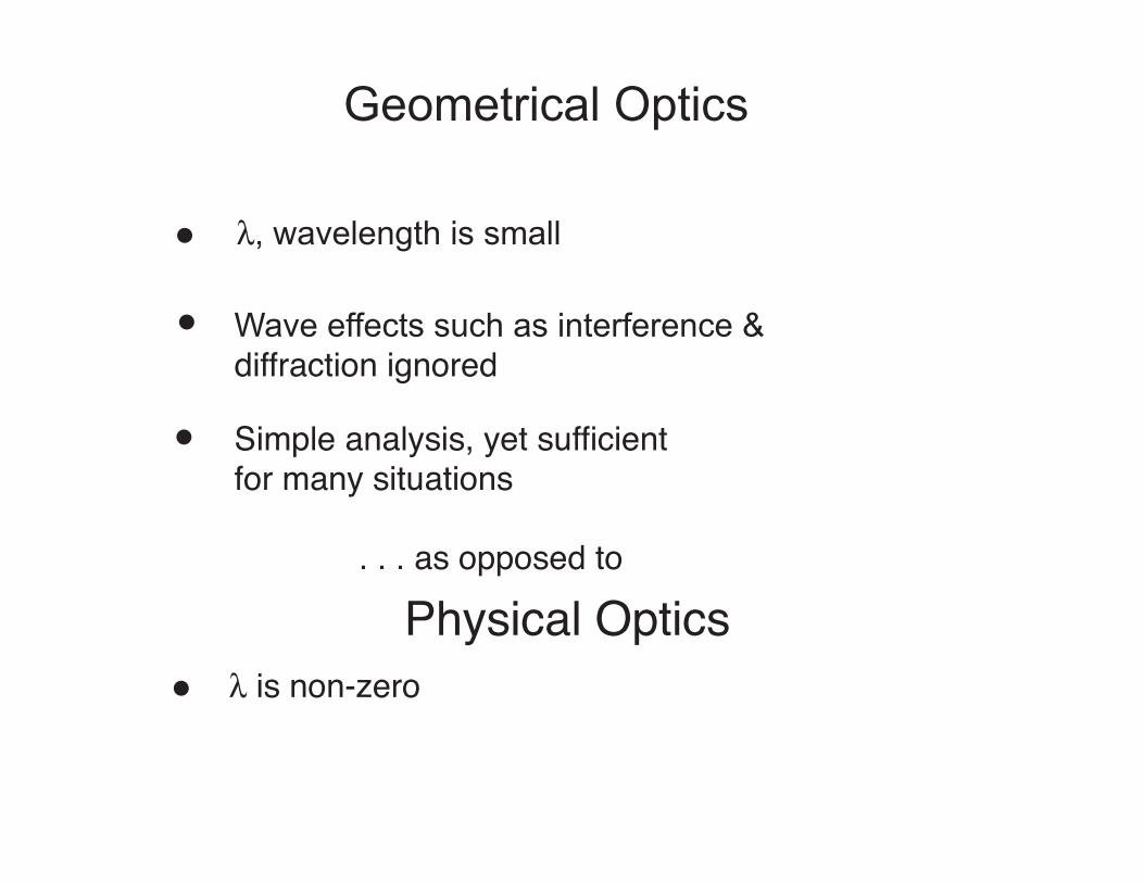
Geometrical Optics
", wavelength is small
Wave effects such as interference & diffraction ignored
Simple analysis, yet sufficient for many situations
. . . as opposed to
Physical Optics" is non-zero
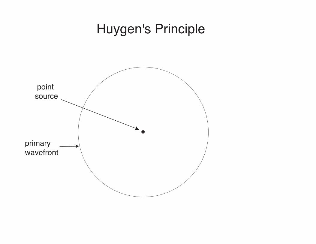
Huygen's Principle
point source
primary wavefront
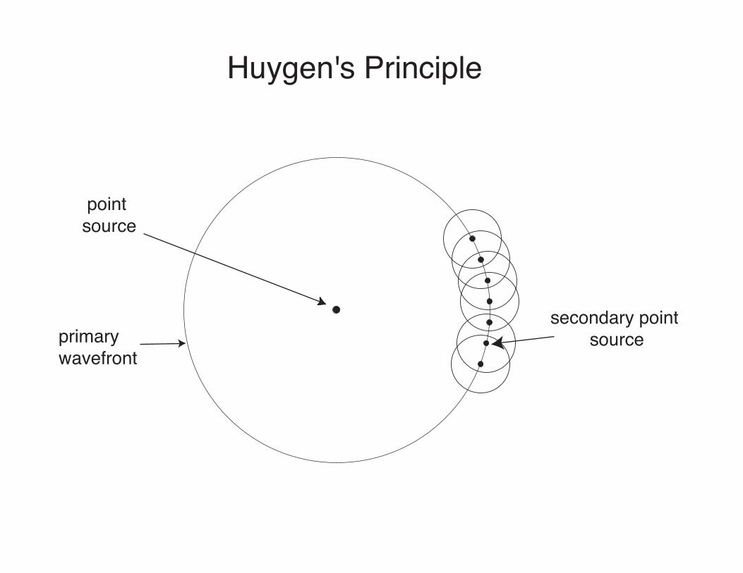
Huygen's Principle
point source
primary wavefront
secondary point source
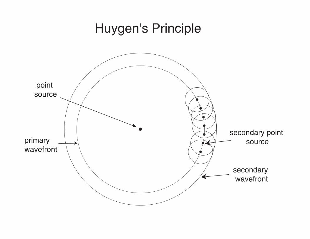
Huygen's Principle
point source
primary wavefront
secondary point source
secondary wavefront
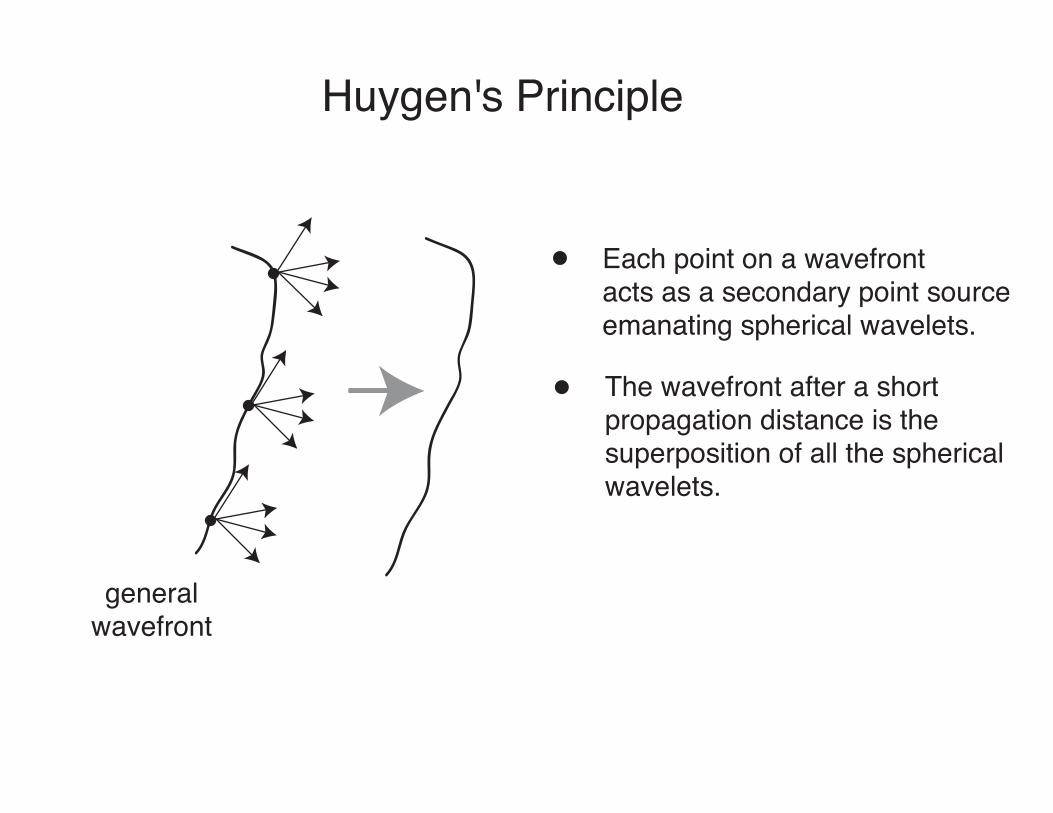
Huygen's Principle
generalwavefront
Each point on a wavefrontacts as a secondary point sourceemanating spherical wavelets.
The wavefront after a short propagation distance is thesuperposition of all the sphericalwavelets.
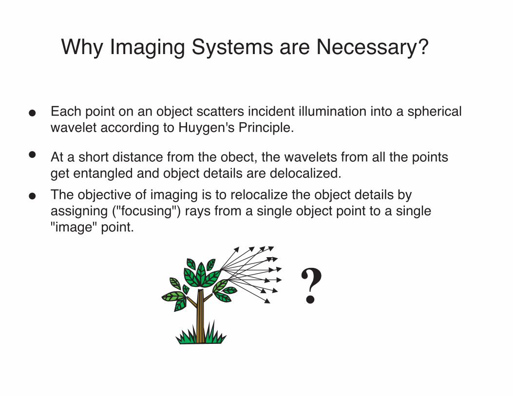
Why Imaging Systems are Necessary?
Each point on an object scatters incident illumination into a sphericalwavelet according to Huygen's Principle.
At a short distance from the obect, the wavelets from all the pointsget entangled and object details are delocalized.The objective of imaging is to relocalize the object details by assigning ("focusing") rays from a single object point to a single "image" point.
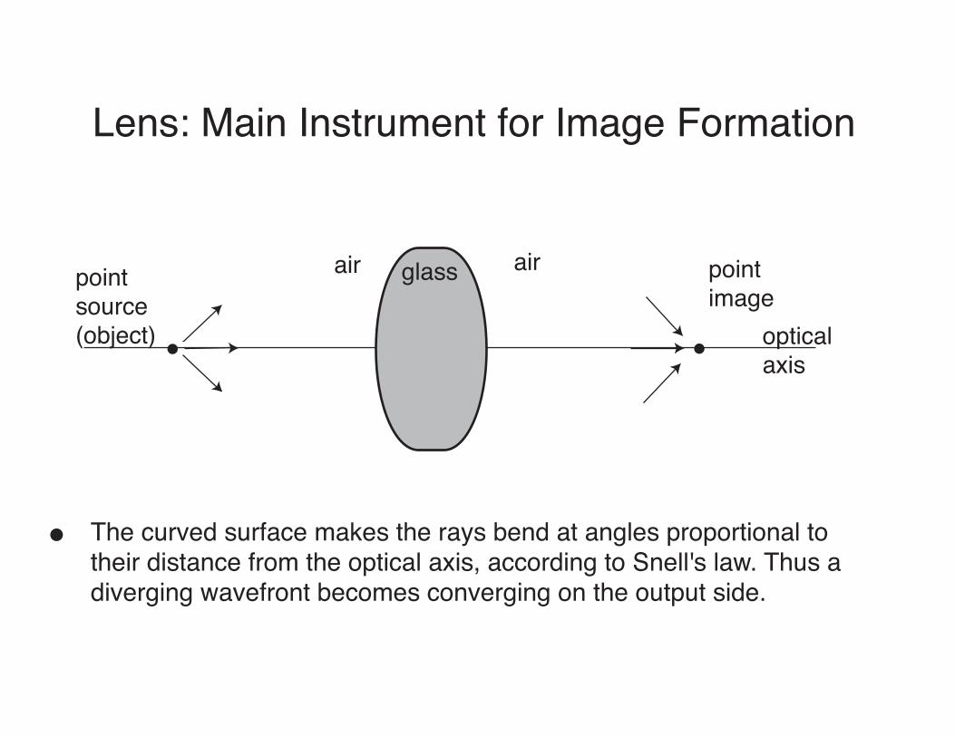
Lens: Main Instrument for Image Formation
The curved surface makes the rays bend at angles proportional to their distance from the optical axis, according to Snell's law. Thus a diverging wavefront becomes converging on the output side.
pointsource(object)
pointimage
opticalaxis
air airglass
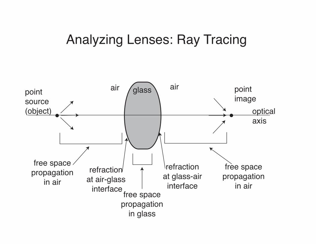
Analyzing Lenses: Ray Tracing
pointsource(object)
pointimage
opticalaxis
air airglass
free spacepropagation
in airrefraction
at air-glass interface free space
propagationin glass
refractionat glass-airinterface
free spacepropagation
in air
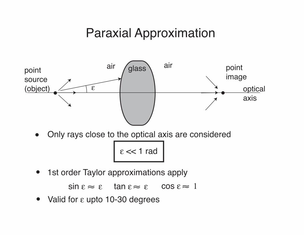
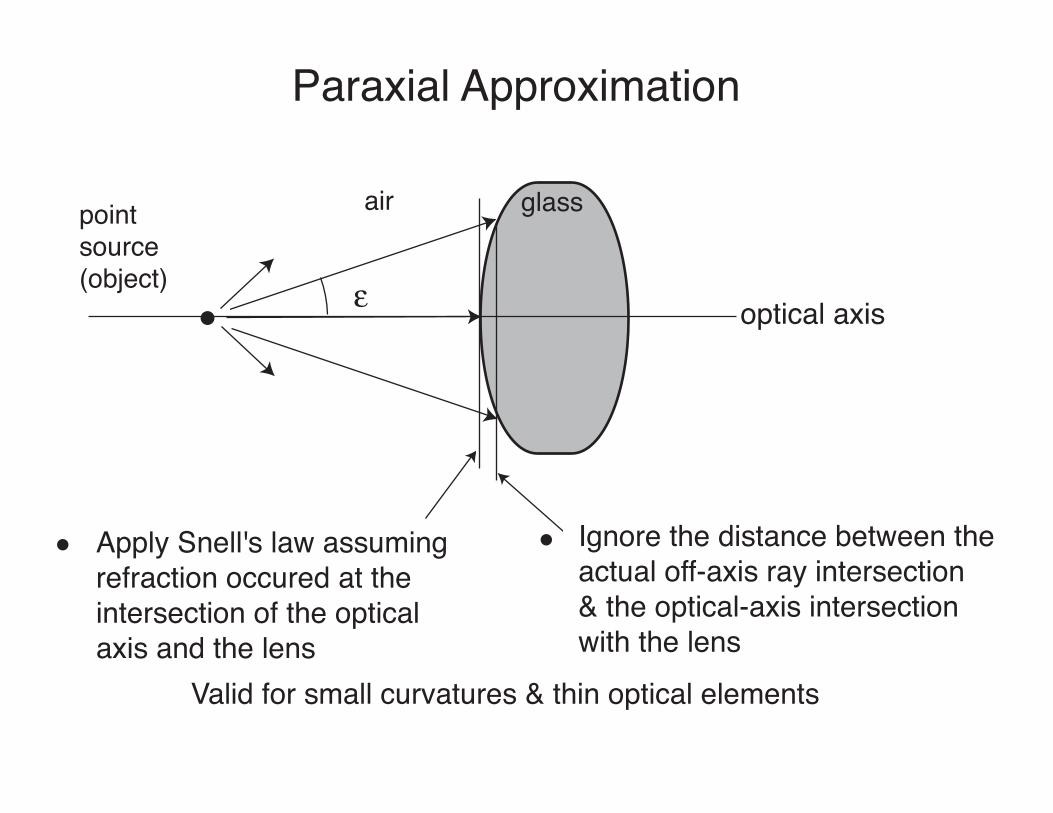
Paraxial Approximation
pointsource(object)
pointimage
opticalaxis
air airglass
&
Only rays close to the optical axis are considered
& << 1 rad
1st order Taylor approximations applysin & & tan & & cos & 1
Valid for & upto 10-30 degrees
Paraxial Approximation
pointsource(object)
air glass
&
Apply Snell's law assuming refraction occured at the intersection of the optical axis and the lens
optical axis
Ignore the distance between theactual off-axis ray intersection& the optical-axis intersectionwith the lens
Valid for small curvatures & thin optical elements
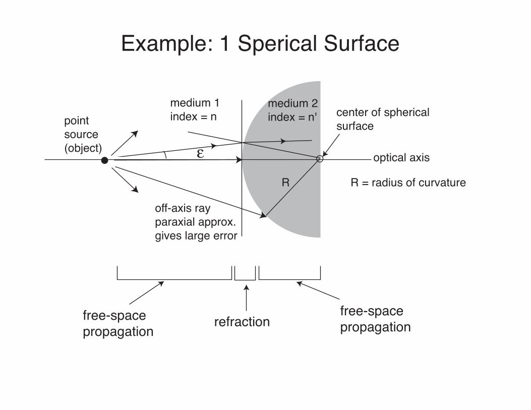
Example: 1 Sperical Surface
pointsource(object)
medium 1index = n
medium 2index = n'
& optical axis
center of sphericalsurface
R R = radius of curvature
off-axis rayparaxial approx.gives large error
free-space propagation refraction
free-space propagation
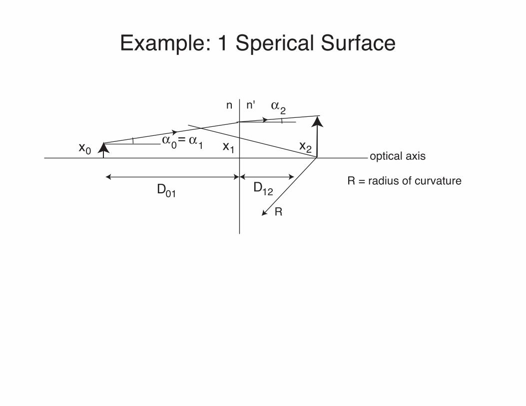
Example: 1 Sperical Surface
n n'
optical axis
R
R = radius of curvatureD01 D12
x0 x1 x2$0
$2
$1=
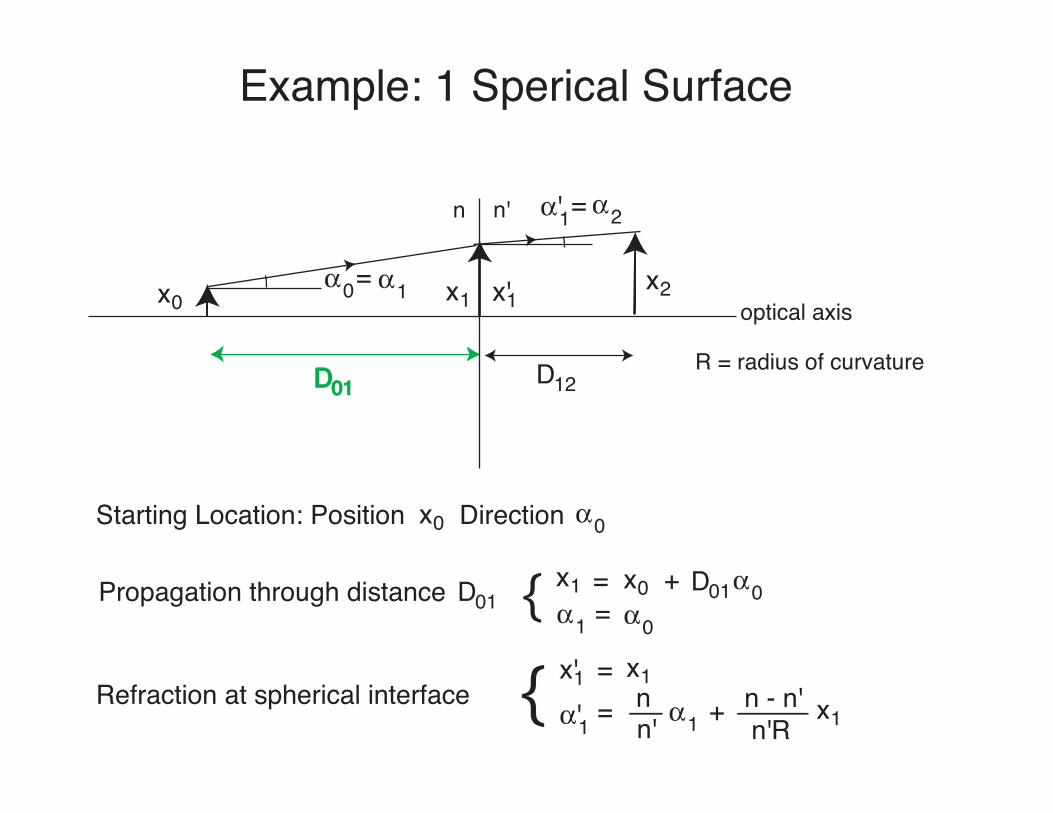
Example: 1 Sperical Surface
n n'
optical axis
R = radius of curvatureD01 D12
x0 x1x2$0
$2
$1=
Starting Location: Position x0 Direction $0
x'1
$'1=
Propagation through distance D01x1 = x0 + D01$0$1 $0={
Refraction at spherical interfacex'1 = x1
$'1 = nn' $1 + n - n'
n'Rx1{
Example: 1 Sperical Surfacen n'
optical axis
R = radius of curvatureD01 D12
x0 x1x2$0
$2
$1= x'1
$'1=
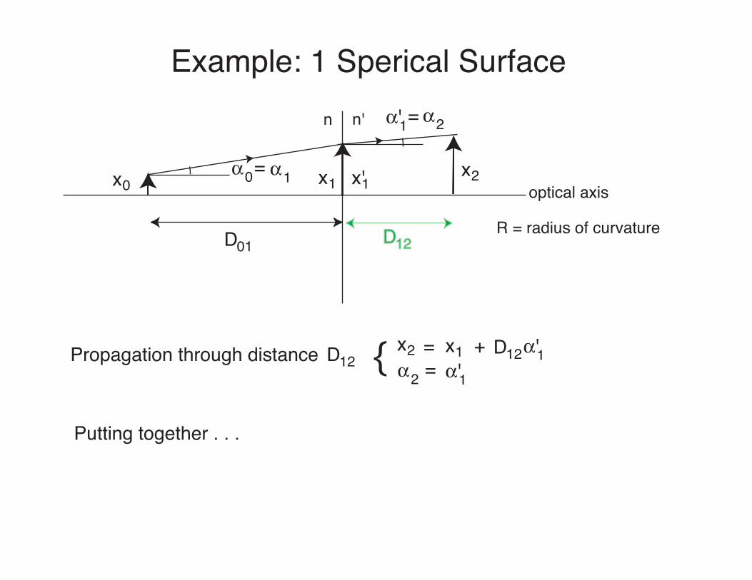
Propagation through distance D12x2 = x1 + D12$'1$2 $'1={
Putting together . . .
Example: 1 Sperical Surfacen n'
optical axis
R = radius of curvatureD01 D12
x0 x1x2$0
$2
$1= x'1
$'1=
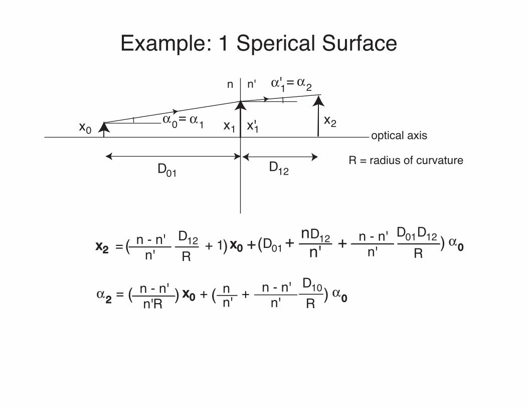
x2 = n - n'n'
D12R
+ 1( ) x0 + D01( + D12nn'
n - n'n'
D12R
+ D01 ) $0
$2n - n'n'R
= ( ) x0 + ( nn' + n - n'
n'D10R ) $0
Sign Conventions
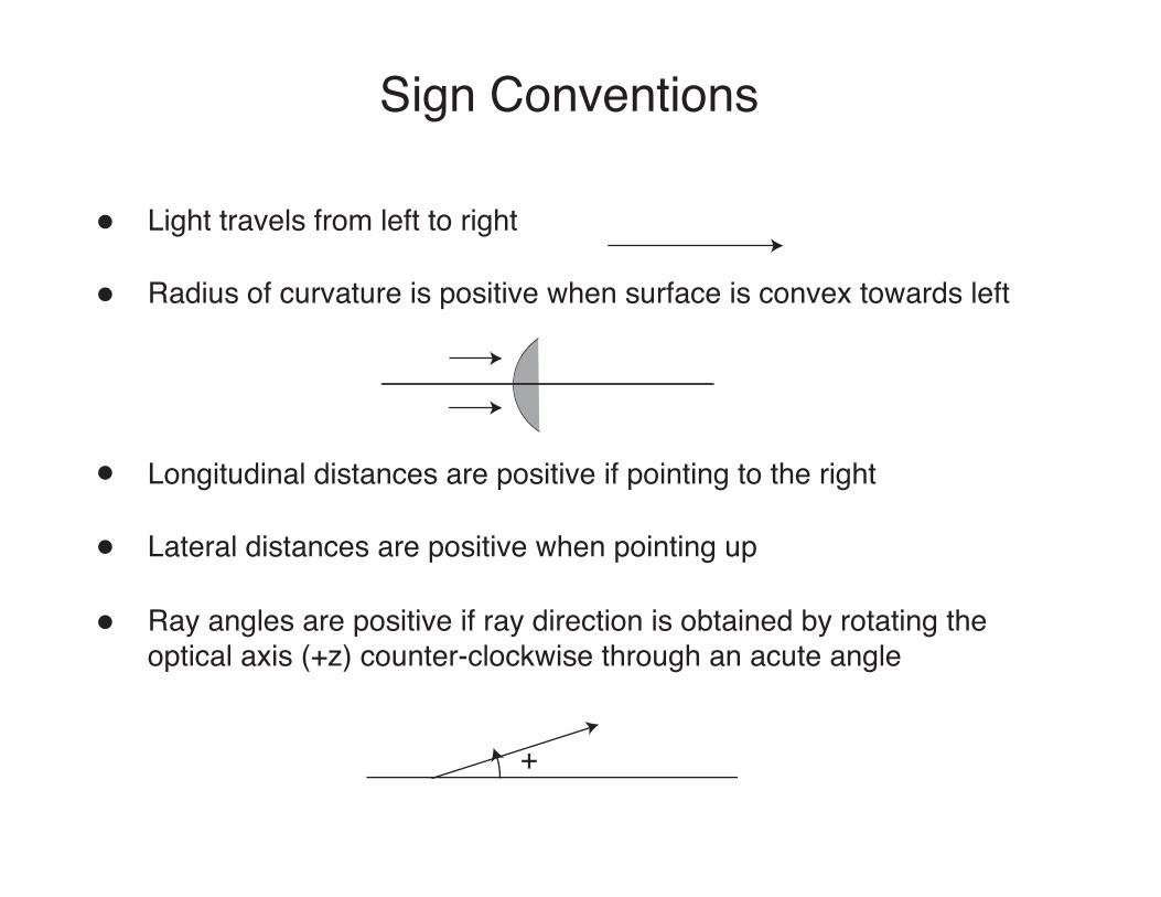
Light travels from left to right
Radius of curvature is positive when surface is convex towards left
Longitudinal distances are positive if pointing to the right
Lateral distances are positive when pointing up
Ray angles are positive if ray direction is obtained by rotating theoptical axis (+z) counter-clockwise through an acute angle
+
On-axis Image Formation
$0
$2
n n'
D01 D12
S P
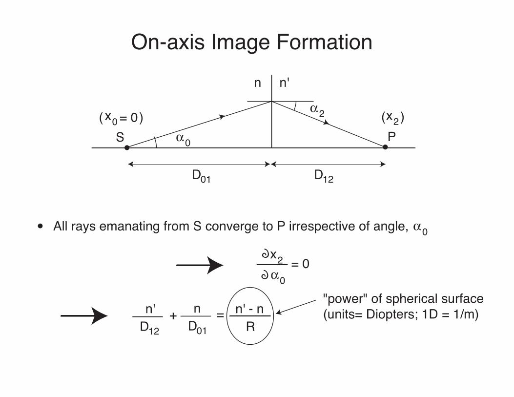
All rays emanating from S converge to P irrespective of angle, $0
x0 = 0 x2( ) ( )
x2$0
= 0
n'D12
+ nD01
= n' - nR
"power" of spherical surface(units= Diopters; 1D = 1/m)
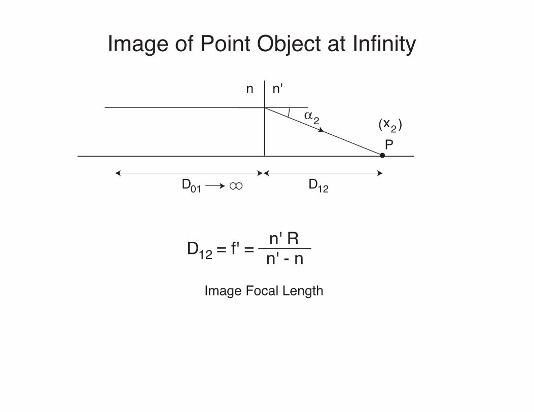
Image of Point Object at Infinity
$2
n n'
D01 D12
Px2( )
D12 = f' = n' - nn' R
Image Focal Length

Point Object Imaged at Infinity
D01 = f = n' - nn R
Object Focal Length
$0
n n'
D01 D12
Sx0 = 0( )
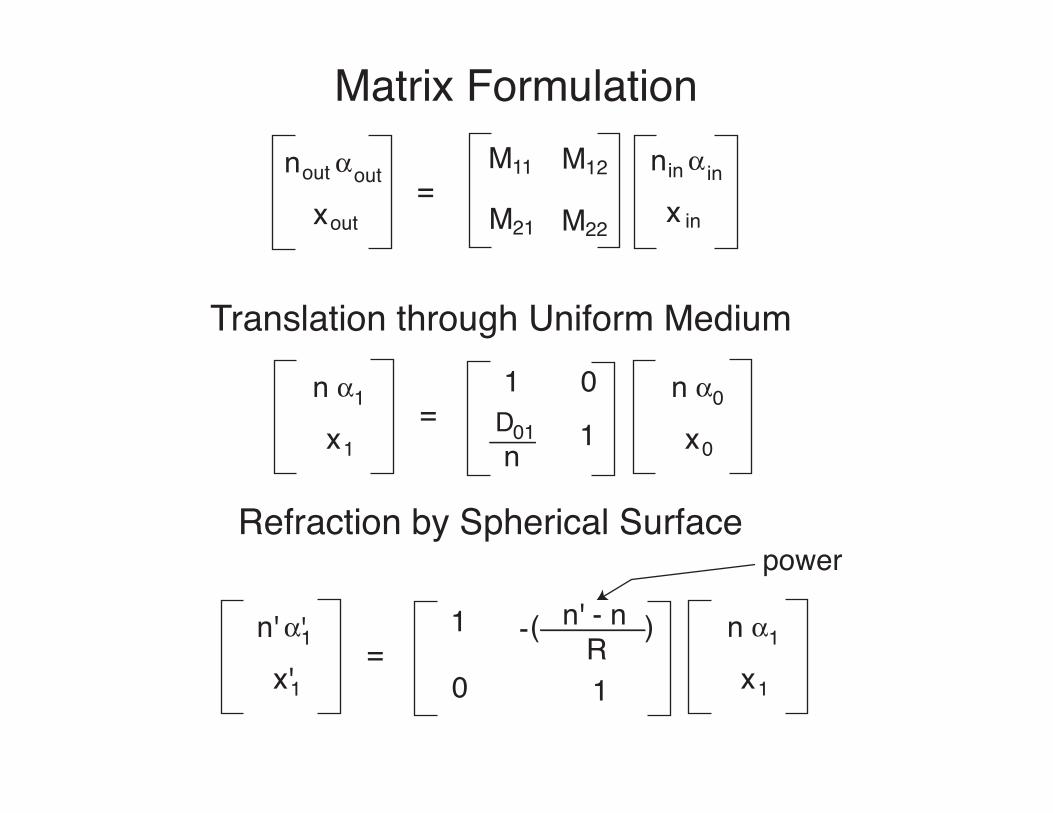
Matrix Formulationnout $out
xout=
M11 M12
M21 M22
nin $ in
x in
Translation through Uniform Medium
n $
x1
1=
1 0D01n 1
n $
x0
0
Refraction by Spherical Surface
n' $'
x'1
1=
1
1
n $
x1
1
n' - nR
( )-
0
power
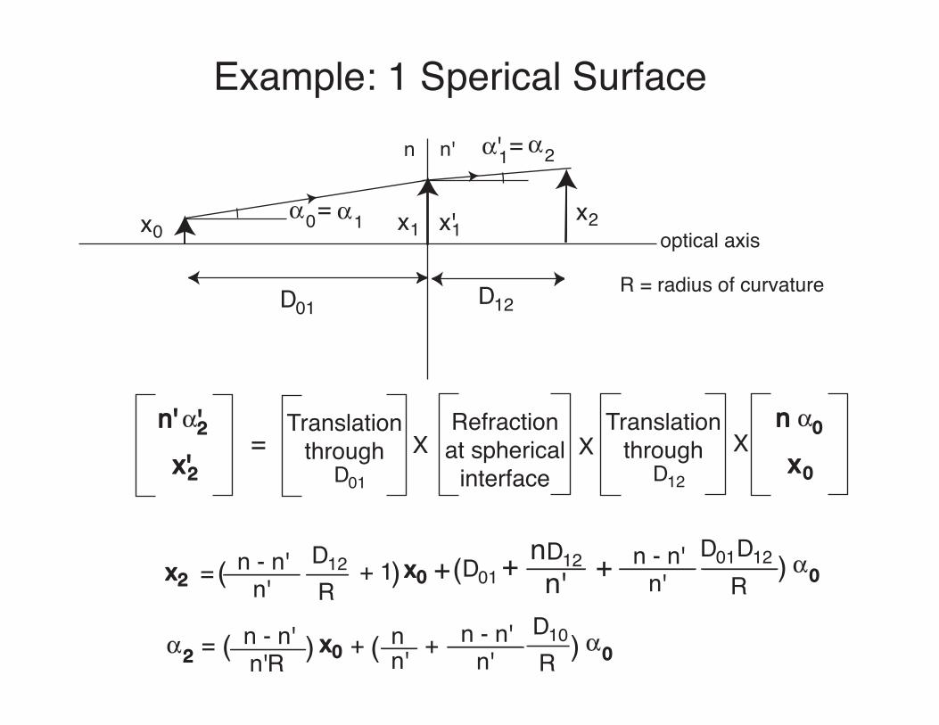
Example: 1 Sperical Surfacen n'
optical axis
R = radius of curvatureD01 D12
x0 x1x2$0
$2
$1= x'1
$'1=
x2 = n - n'n'
D12R
+ 1( ) x0 + D01( + D12nn'
n - n'n'
D12R
+ D01 ) $0
$2n - n'n'R
= ( ) x0 + ( nn' + n - n'
n'D10R ) $0
n' $'
x'2
2=
Translationthrough
D01
XRefraction
at sphericalinterface
XTranslation
throughD12
Xn $
x0
0
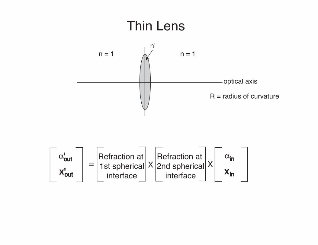
Thin Lens
n = 1n'
optical axis
R = radius of curvature
$'out
x'out= X X
$in
x in
n = 1
Refraction at 1st spherical
interface
Refraction at 2nd spherical
interface
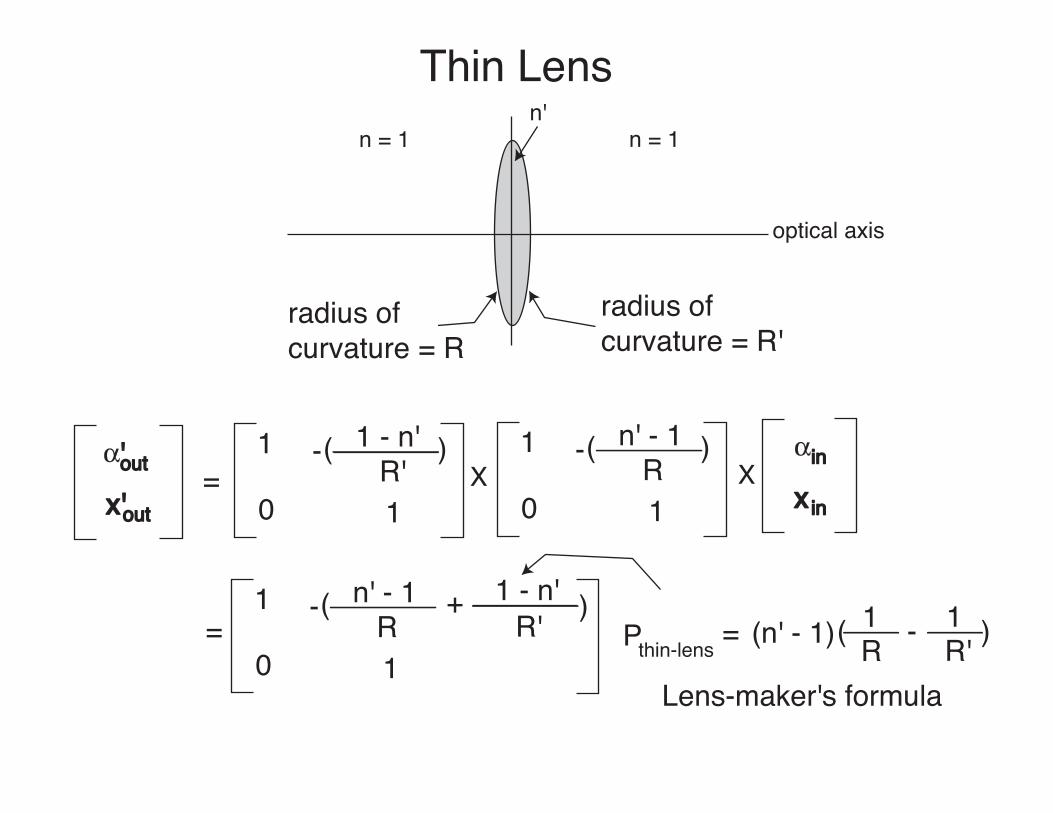
Thin Lensn = 1
n'
optical axis
$'out
x'out= X
$in
x in
n = 1
1
1
1 - n'R'
( )-
0X
radius ofcurvature = R
radius ofcurvature = R'
=1
1
n' - 1R
( )-
0
+ 1 - n'R' Pthin-lens = (n' - 1) 1
R1R'-( )
Lens-maker's formula
1
1
n' - 1R
( )-
0
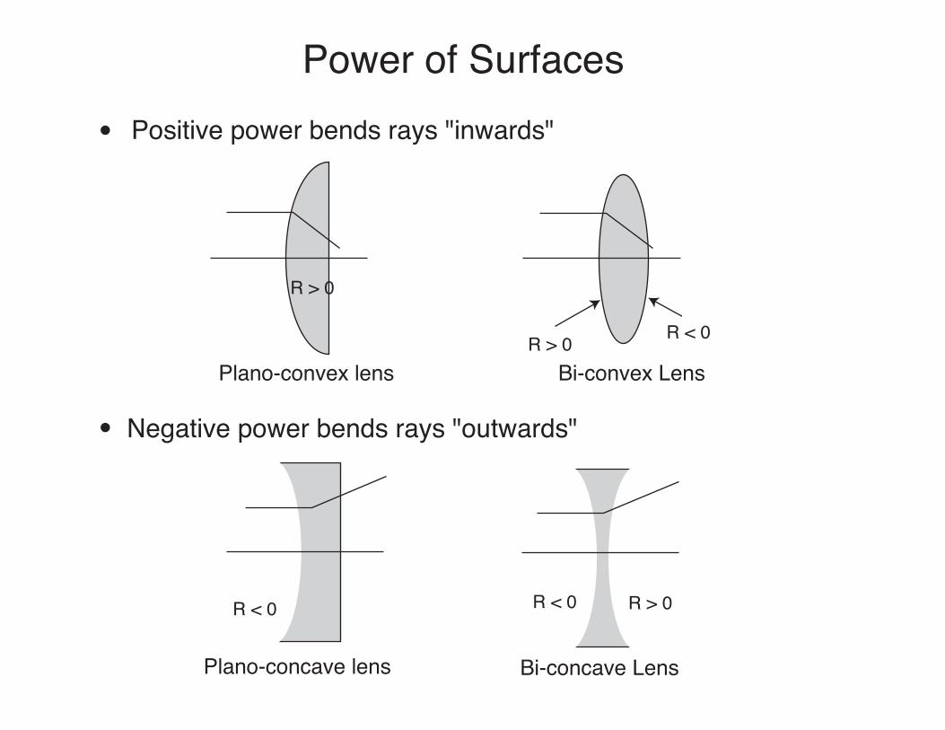
Power of SurfacesPositive power bends rays "inwards"
R > 0
Plano-convex lensR > 0 R < 0
Bi-convex Lens
Negative power bends rays "outwards"
R < 0
Plano-concave lens
R < 0 R > 0
Bi-concave Lens
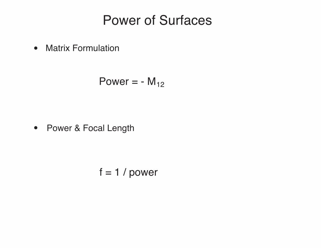
Power of Surfaces
Matrix Formulation
Power & Focal Length
Power = - M12
f = 1 / power
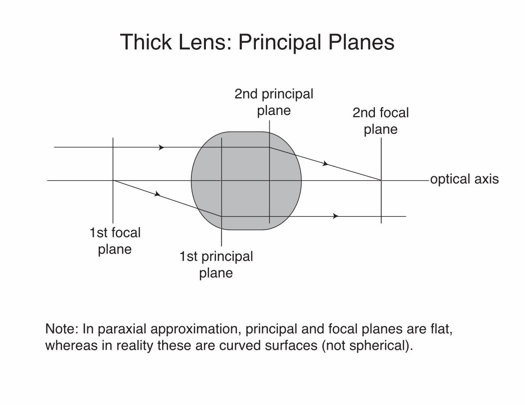
Thick Lens: Principal Planes
1st focalplane 1st principal
plane
2nd principalplane 2nd focal
plane
optical axis
Note: In paraxial approximation, principal and focal planes are flat,whereas in reality these are curved surfaces (not spherical).
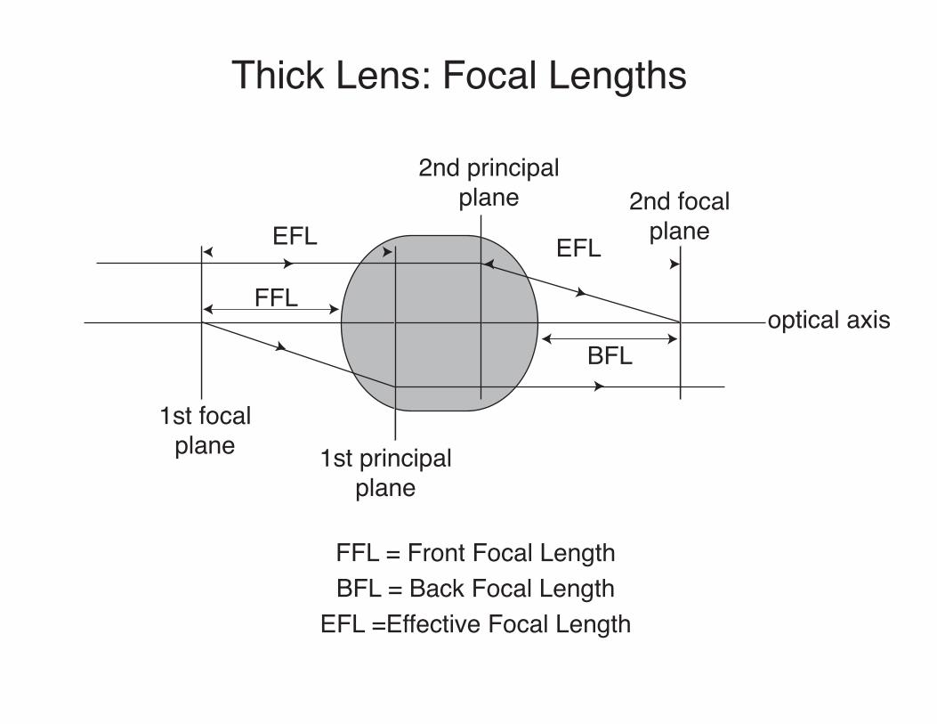
Thick Lens: Focal Lengths
1st focalplane 1st principal
plane
2nd principalplane 2nd focal
plane
optical axisFFL
EFL
BFL
EFL
FFL = Front Focal LengthBFL = Back Focal Length
EFL =Effective Focal Length
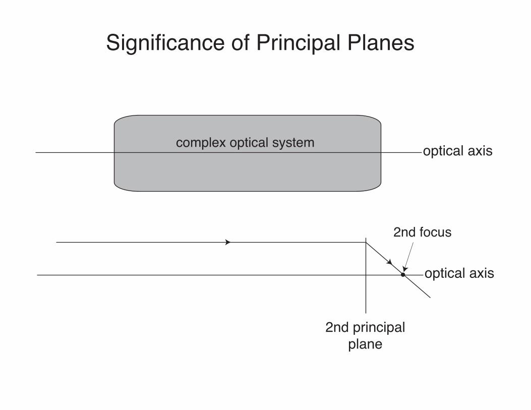
Significance of Principal Planes
2nd principalplane
optical axiscomplex optical system
optical axis
2nd focus
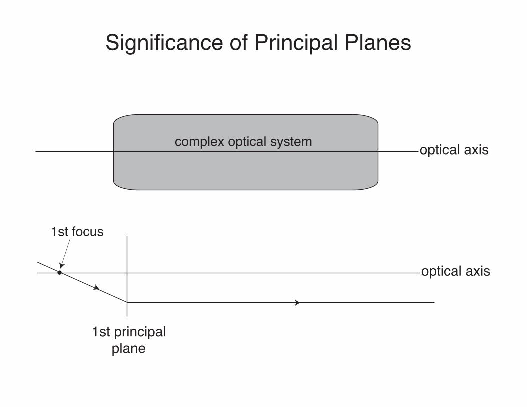
Significance of Principal Planes
1st principalplane
optical axiscomplex optical system
optical axis
1st focus
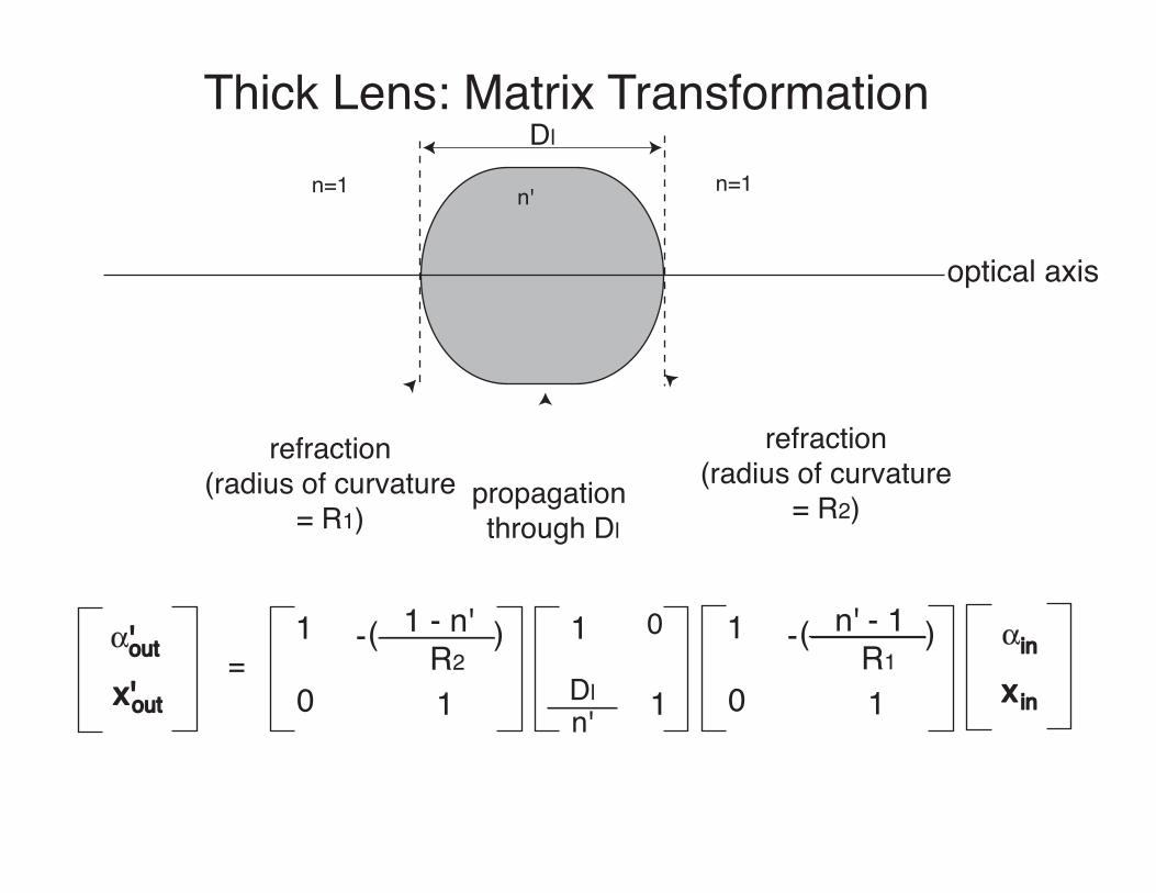
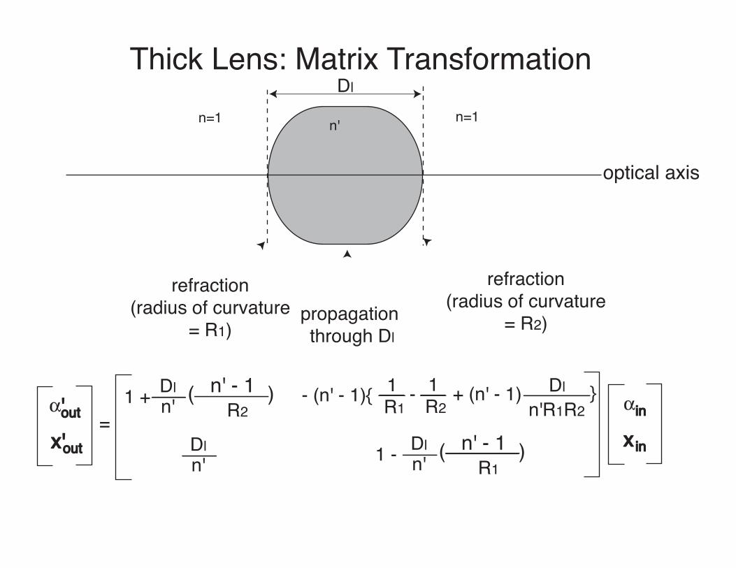
Thick Lens: Matrix Transformation
optical axis
Dl
refraction(radius of curvature
= R1)propagation through Dl
refraction(radius of curvature
= R2)
n=1 n' n=1
$'out
x'out=
1
1
1 - n'R2
( )-
0
1
1
0
Dln'
1
1
n' - 1R1
( )-
0
$in
x in
Thick Lens: Matrix Transformation
optical axis
Dl
refraction(radius of curvature
= R1)propagation through Dl
refraction(radius of curvature
= R2)
n=1 n' n=1
$'out
x'out=
$in
x in
Dln'
n' - 1R2
( )1 + - (n' - 1){ 1R1
- 1R2
+ (n' - 1) Dln'R1R2
Dln'
Dln'
n' - 1R1
( )1 -
}
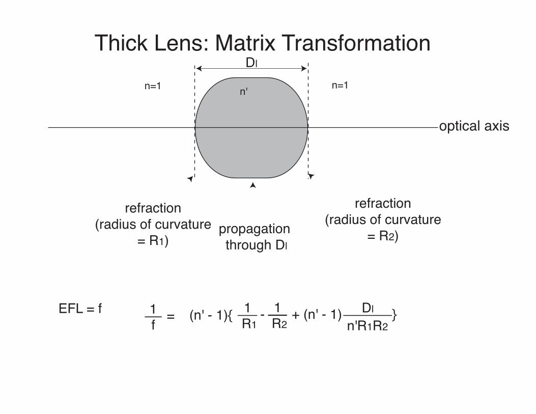
Thick Lens: Matrix Transformation
optical axis
Dl
refraction(radius of curvature
= R1)propagation through Dl
refraction(radius of curvature
= R2)
n=1 n' n=1
(n' - 1){ 1R1
- 1R2
+ (n' - 1) Dln'R1R2
EFL = f 1f = }
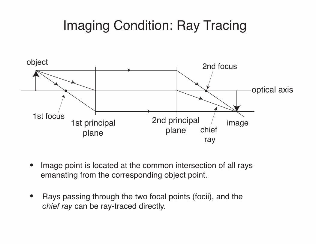
Imaging Condition: Ray Tracing
1st principalplane
optical axis
1st focus 2nd principalplane
2nd focusobject
image
Image point is located at the common intersection of all rays emanating from the corresponding object point.
Rays passing through the two focal points (focii), and the chief ray can be ray-traced directly.
chief ray
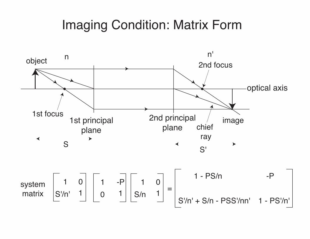
Imaging Condition: Matrix Form
1st principalplane
optical axis
1st focus 2nd principalplane
2nd focusobject
imagechief ray
S S'
systemmatrix
n n'
1 0S'/n' 1
1 -P0 1
1 0S/n 1 =
1 - PS/n -P
S'/n' + S/n - PSS'/nn' 1 - PS'/n'
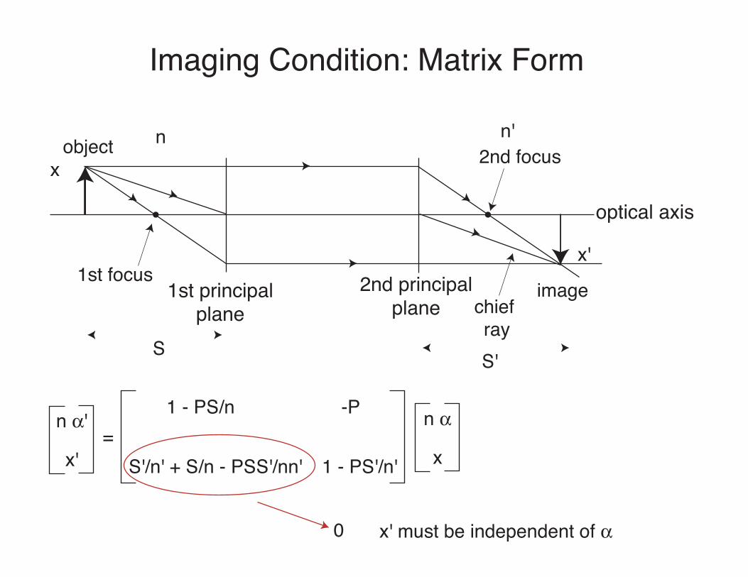
Imaging Condition: Matrix Form
1st principalplane
optical axis
1st focus 2nd principalplane
2nd focusobject
imagechief ray
S S'
n n'
=1 - PS/n -P
S'/n' + S/n - PSS'/nn' 1 - PS'/n'
x
x'
n $'
x'
n $
x
0 x' must be independent of $
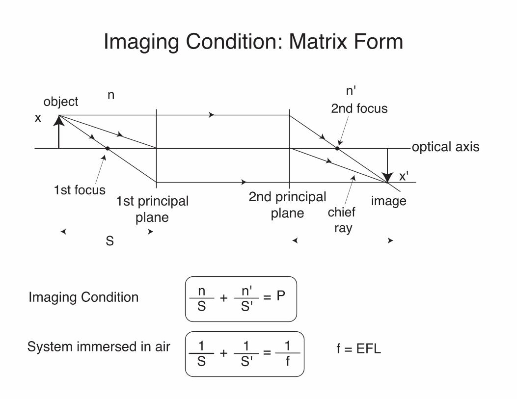
Imaging Condition: Matrix Form
1st principalplane
optical axis
1st focus 2nd principalplane
2nd focusobject
imagechief ray
S
n n'
x
x'
Imaging Condition nS
n'S'+ = P
System immersed in air 1S
1S'+ = 1
ff = EFL
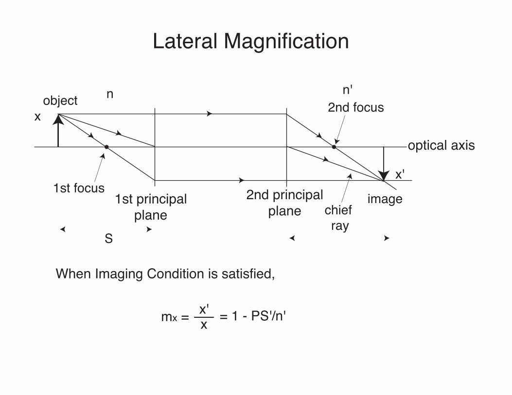
Lateral Magnification
1st principalplane
optical axis
1st focus 2nd principalplane
2nd focusobject
imagechief ray
S
n n'
x
x'
When Imaging Condition is satisfied,
mx = x'x = 1 - PS'/n'
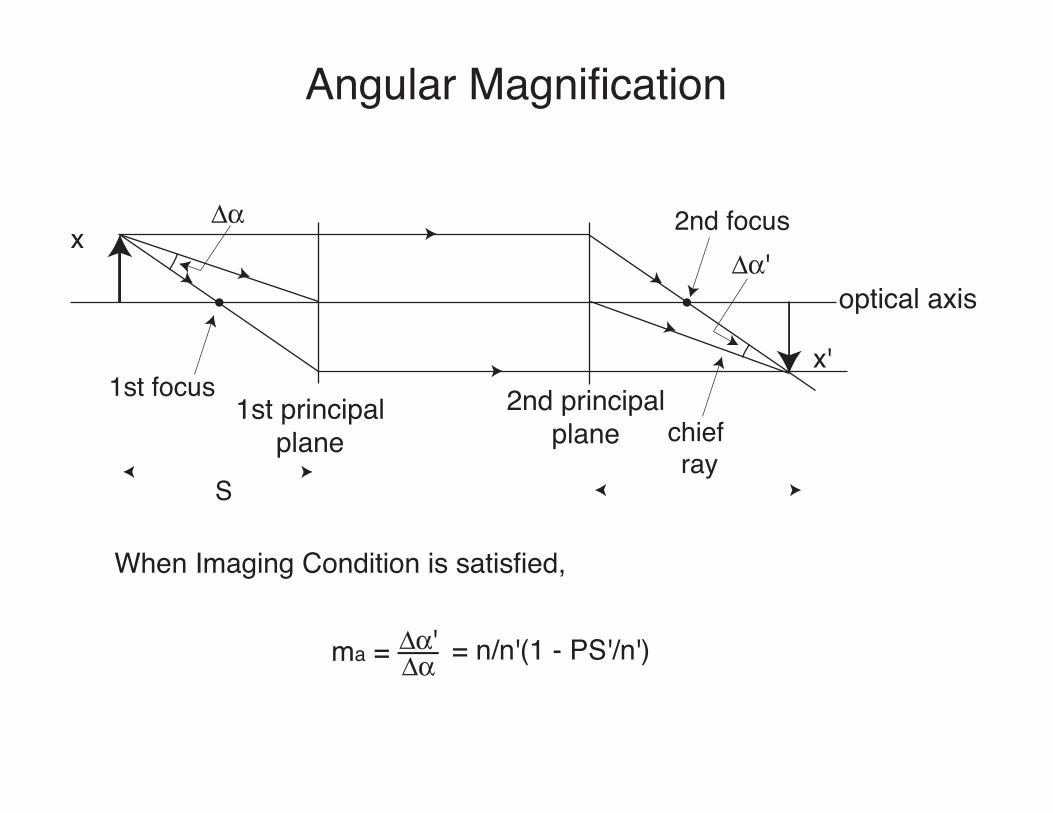
Angular Magnification
1st principalplane
optical axis
1st focus 2nd principalplane
2nd focus
chief ray
S
x
x'
When Imaging Condition is satisfied,
ma = = n/n'(1 - PS'/n')
#$
#$'
#$'#$
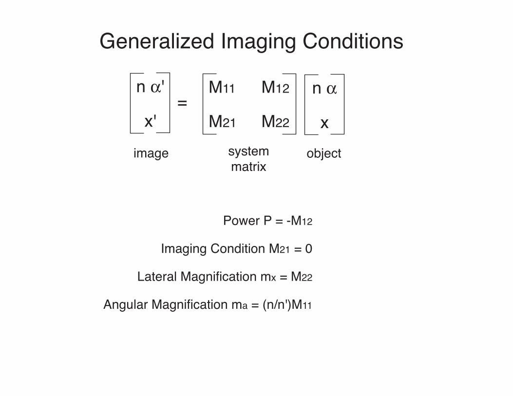
Generalized Imaging Conditions
n $'
x'
n $
x
M11 M12
M21 M22=
image systemmatrix
object
Power P = -M12
Imaging Condition M21 = 0
Lateral Magnification mx = M22
Angular Magnification ma = (n/n')M11
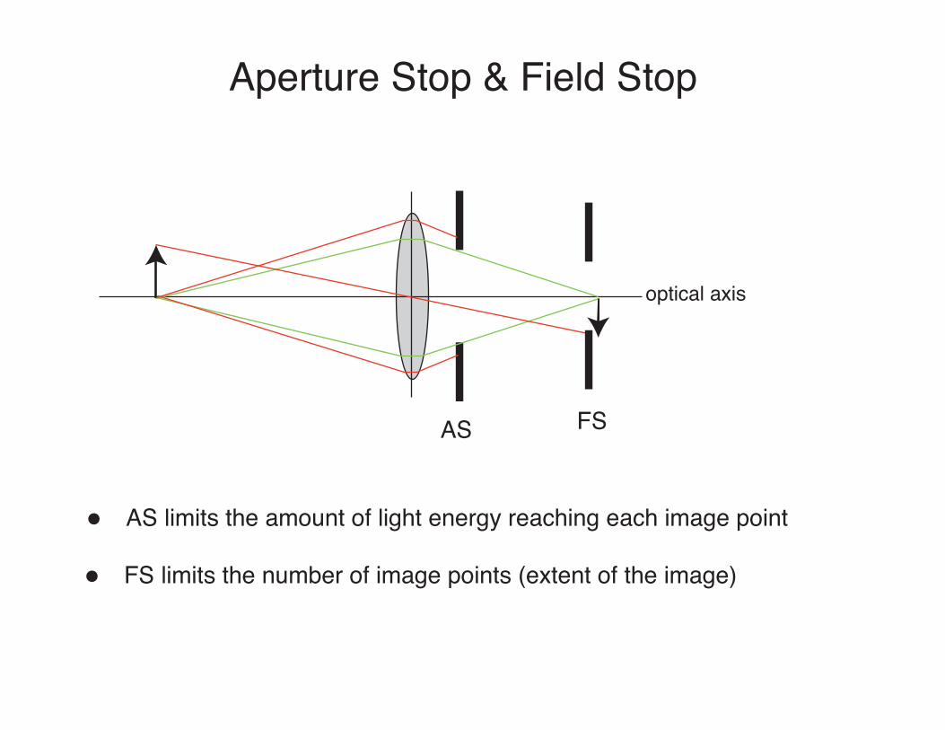
Aperture Stop & Field Stop
optical axis
AS FS
AS limits the amount of light energy reaching each image point
FS limits the number of image points (extent of the image)
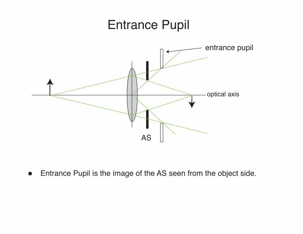
Entrance Pupil
optical axis
AS
Entrance Pupil is the image of the AS seen from the object side.
entrance pupil
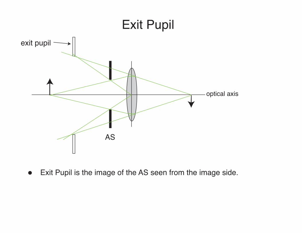
Exit Pupil
optical axis
AS
Exit Pupil is the image of the AS seen from the image side.
exit pupil
Mirrors & prisms
• Last time: optical elements,
– Lenses• Basic properties of spherical surfaces• Ray tracing• Image formation• Magnification
• Today: more optical elements,– Prisms– Mirrors
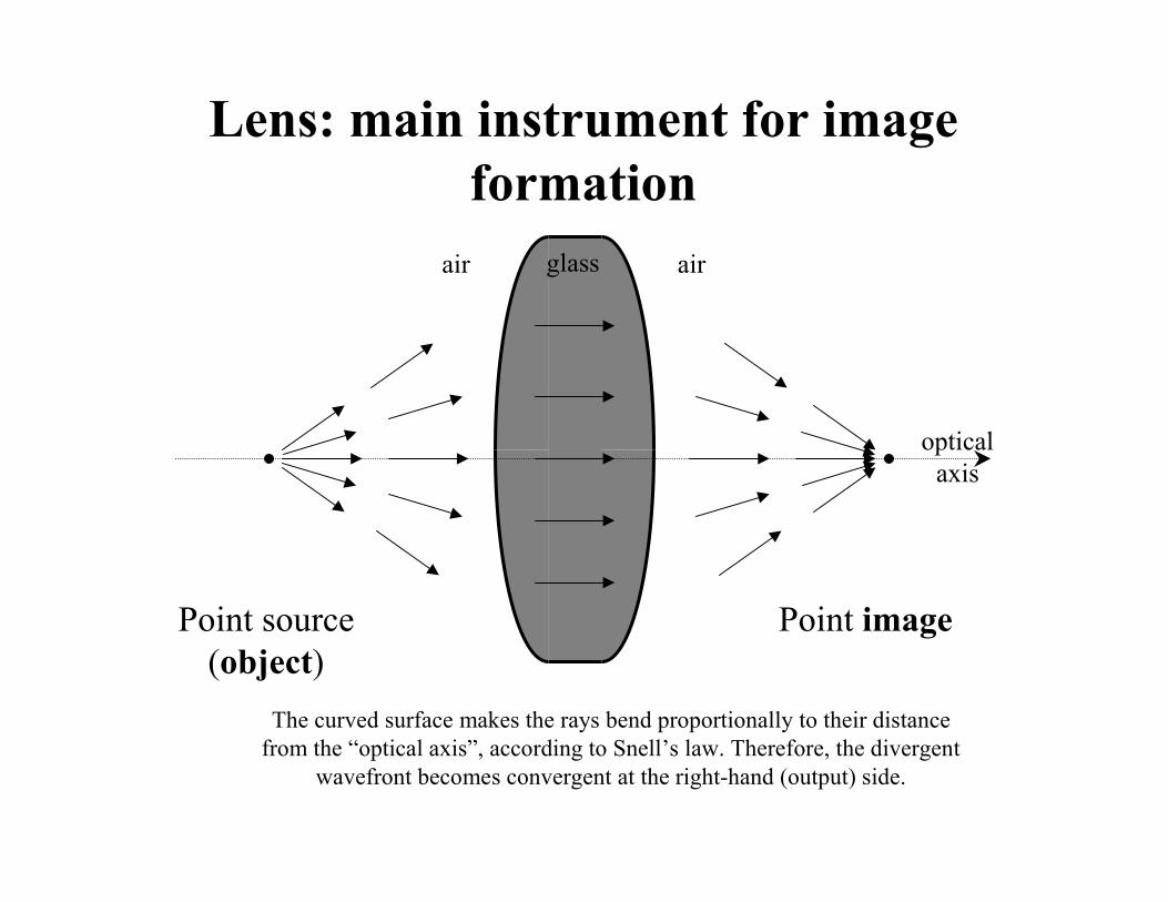
Lens: main instrument for image formation
Point source(object)
Point image
The curved surface makes the rays bend proportionally to their distance from the “optical axis”, according to Snell’s law. Therefore, the divergent
wavefront becomes convergent at the right-hand (output) side.
air glass air
opticalaxis

Cardinal Planes and Points
• Rays generated from axial point at infinity (i.e., forming a ray bundle parallel to the optical axis) and entering an optical system intersect the optical axis at the Focal Points.Focal Points.
• The intersection of the extended entering parallel rays and the extended exiting convergent rays forms the Principal SurfacePrincipal Surface (PlanePlane in the paraxial approximation.)
• The extension of a ray which enters and exits the optical system with the same angle of propagation intersects the optical axis at the Nodal Nodal Points.Points.
2nd PS
1st PS
2nd FP1st FP 2nd NP1st NP
n n´
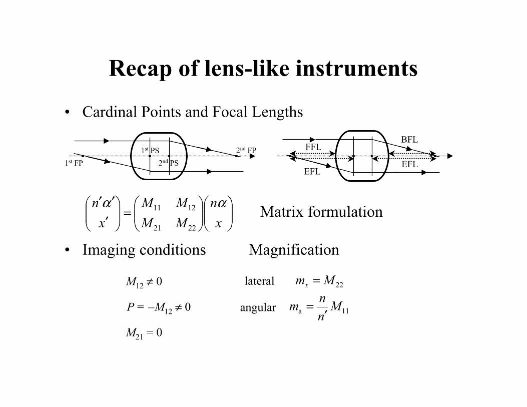
Recap of lens-like instruments
• Cardinal Points and Focal Lengths
• Imaging conditions
2nd PS1st PS 2nd FP
1st FP EFL
BFLFFL
EFL
!!"
#$$%
&!!"
#$$%
&=!!"
#$$%
&
!!!
xn
MMMM
xn ""
2221
1211
M12 # 0
P = –M12 # 0
M21 = 0
22Mmx =
11a Mnn
m!
=
Magnification
lateral
angular
Matrix formulation
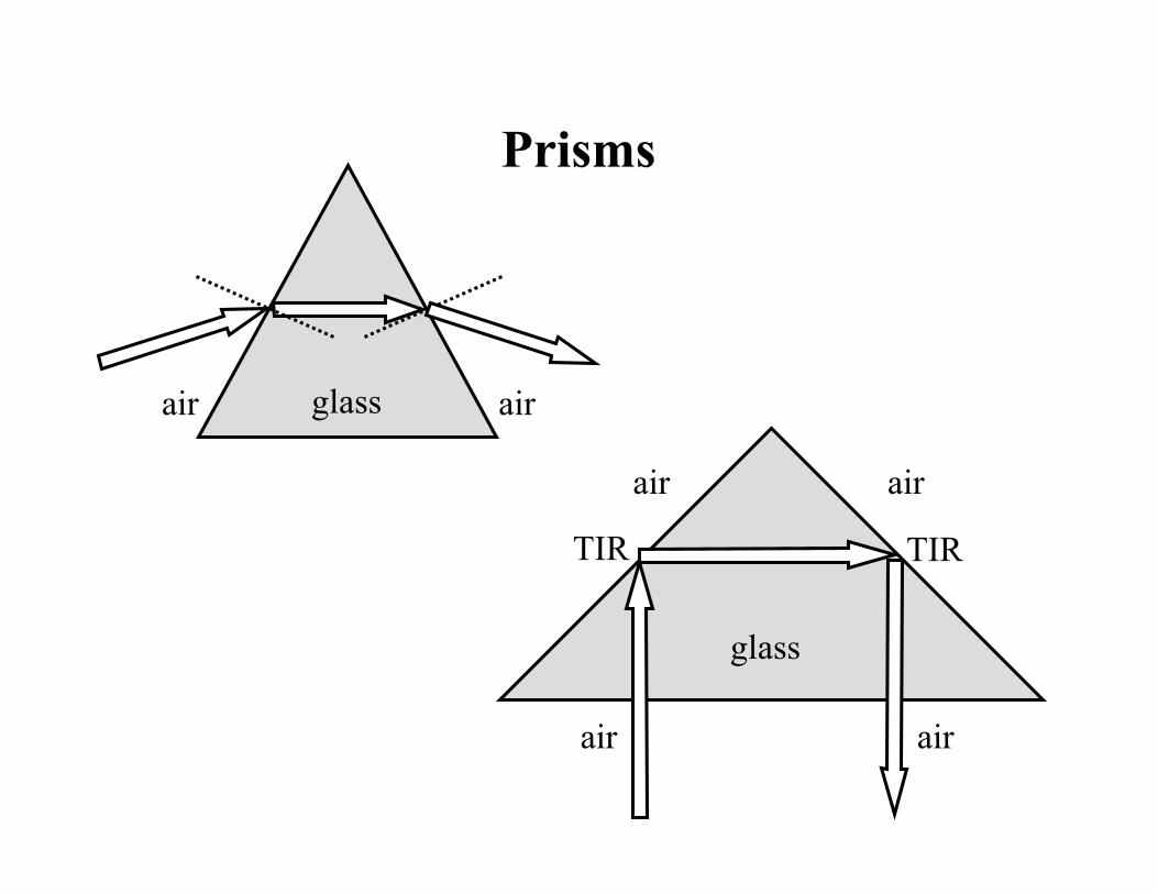
Prisms
glassair air
TIR TIR
glass
air air
airair
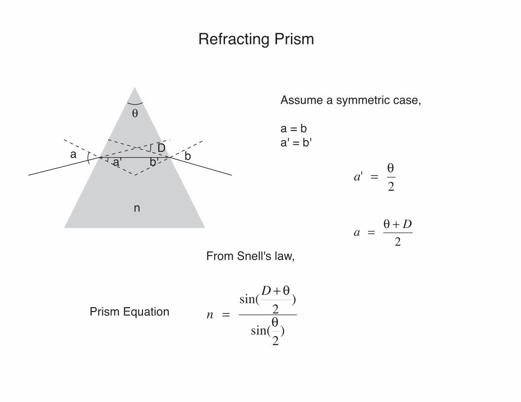
Refracting Prism
Da a' b' b
Assume a symmetric case,
a = ba' = b'
!
a' = !2
a = ! + D2
n = sin(D+ !
2)
sin(!2
)
From Snell's law,
n
Prism Equation
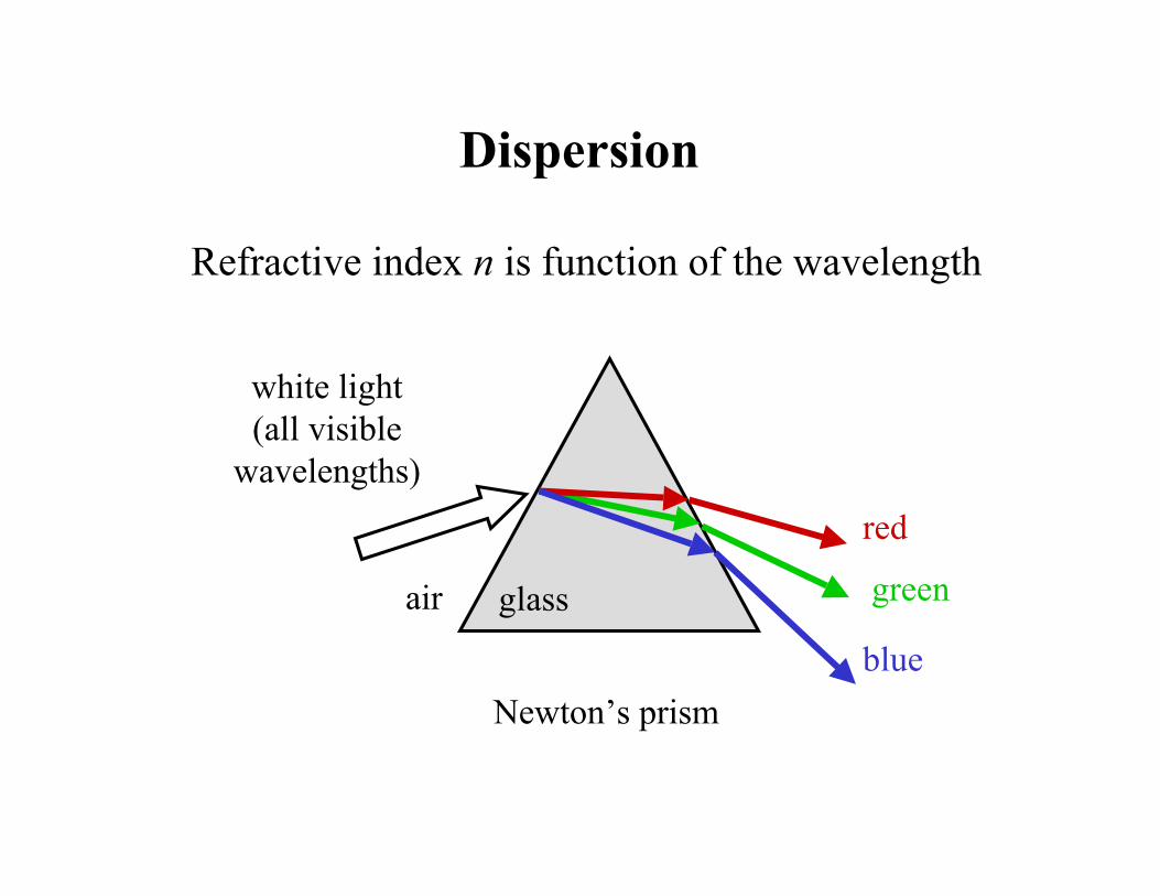
Dispersion
Refractive index n is function of the wavelength
white light(all visible
wavelengths)
Newton’s prism
red
green
blue
glassair
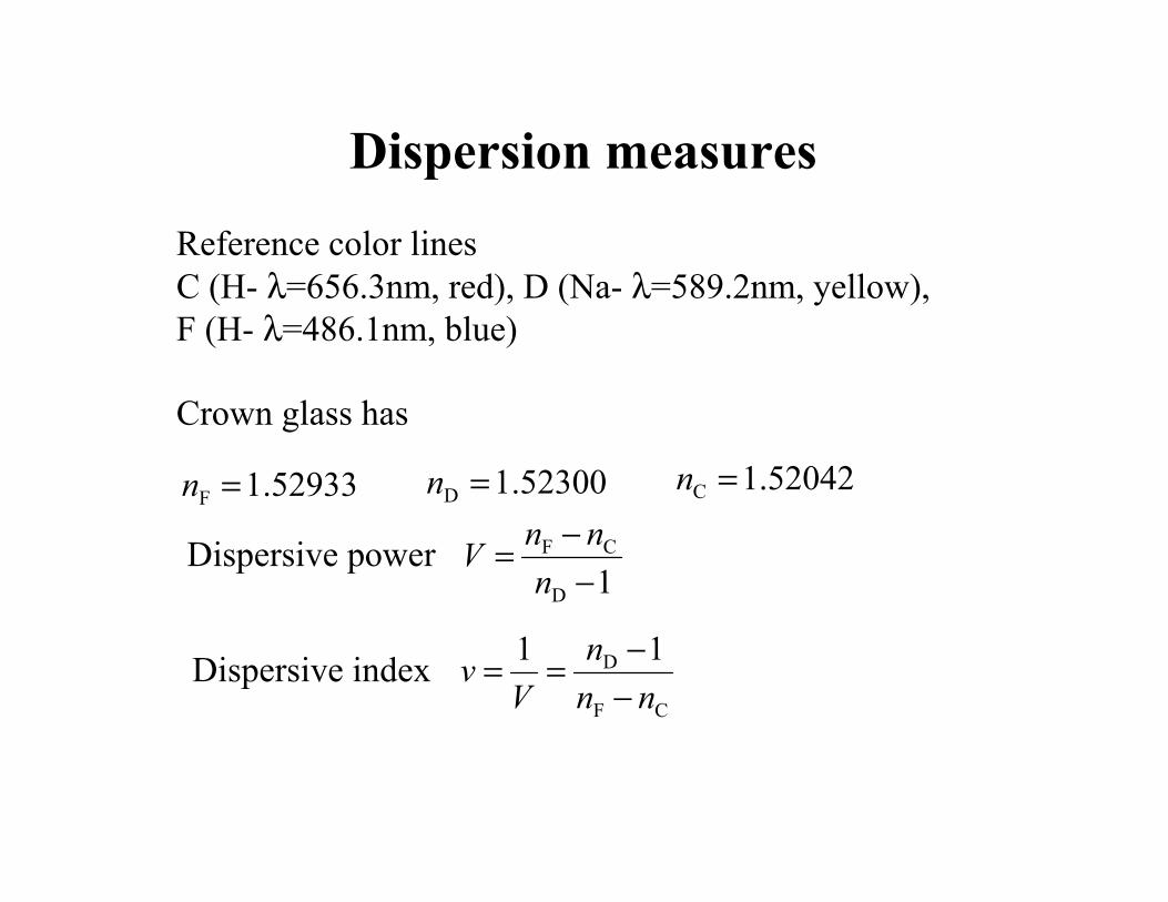
Dispersion measures
Reference color linesC (H- $=656.3nm, red), D (Na- $=589.2nm, yellow), F (H- $=486.1nm, blue)
Crown glass has
52933.1F =n 52300.1D =n 52042.1C =n
1D
CF
%%=
nnn
V
CF
D 11nn
nV
v%%==
Dispersive power
Dispersive index
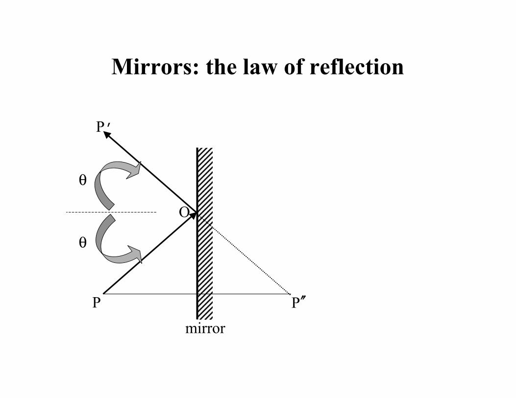
Mirrors: the law of reflection
P
P’
O
P !!mirror
&
&
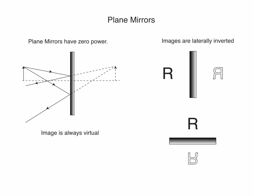
Plane Mirrors
Plane Mirrors have zero power.
Image is always virtual
Images are laterally inverted
R R
RR
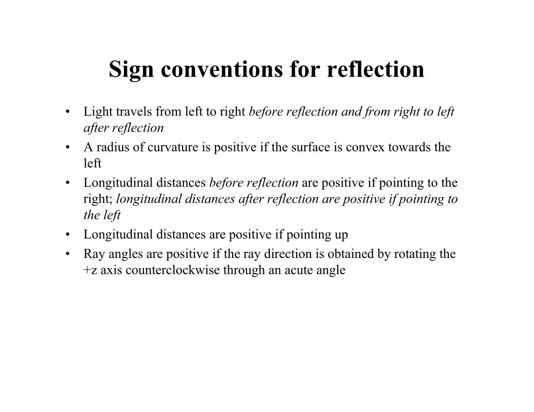
Sign conventions for reflection
• Light travels from left to right before reflection and from right to left after reflection
• A radius of curvature is positive if the surface is convex towards the left
• Longitudinal distances before reflection are positive if pointing to the right; longitudinal distances after reflection are positive if pointing to the left
• Longitudinal distances are positive if pointing up• Ray angles are positive if the ray direction is obtained by rotating the
+z axis counterclockwise through an acute angle
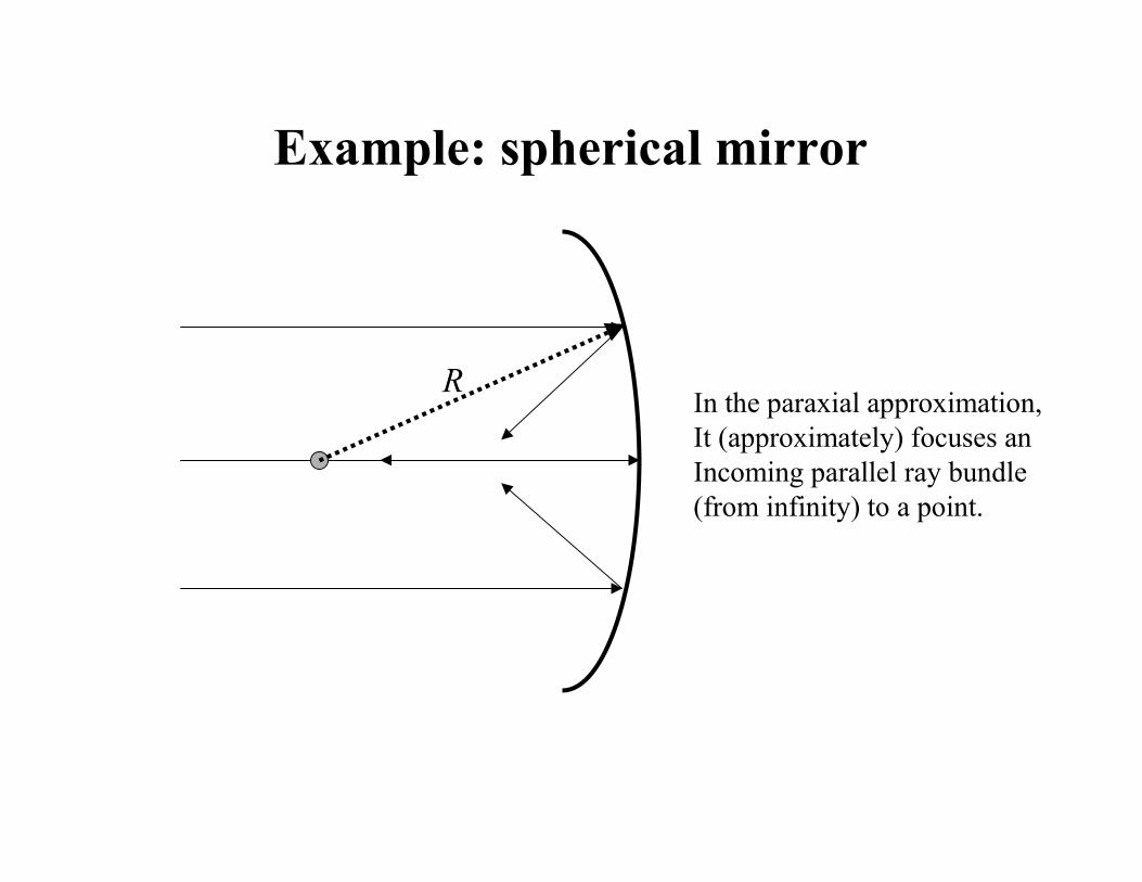
Example: spherical mirror
In the paraxial approximation,It (approximately) focuses anIncoming parallel ray bundle(from infinity) to a point.
R
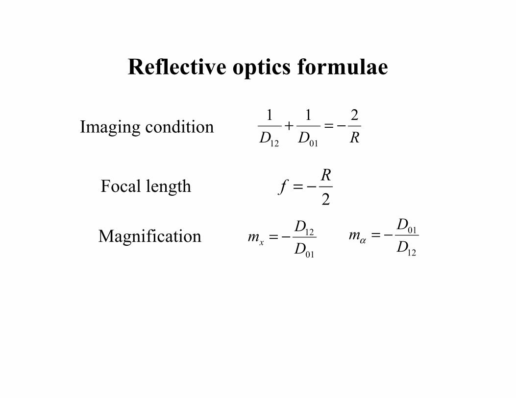
Reflective optics formulae
RDD211
0112
%=+
2R
f %=
01
12
DD
mx %=12
01
DD
m %="
Imaging condition
Focal length
Magnification
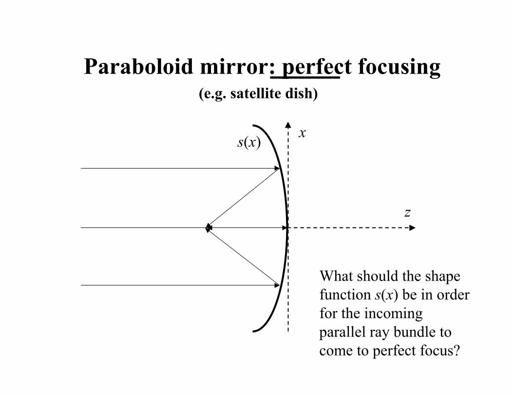
Paraboloid mirror: perfect focusing
s(x) x
z
(e.g. satellite dish)
What should the shape function s(x) be in order for the incoming parallel ray bundle to come to perfect focus?
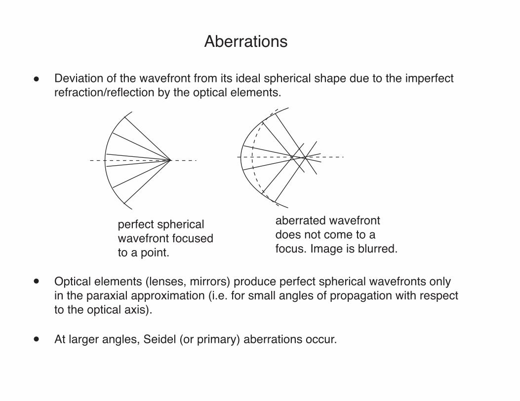
Aberrations
Deviation of the wavefront from its ideal spherical shape due to the imperfectrefraction/reflection by the optical elements.
perfect spherical wavefront focused to a point.
aberrated wavefrontdoes not come to a focus. Image is blurred.
Optical elements (lenses, mirrors) produce perfect spherical wavefronts onlyin the paraxial approximation (i.e. for small angles of propagation with respectto the optical axis).
At larger angles, Seidel (or primary) aberrations occur.
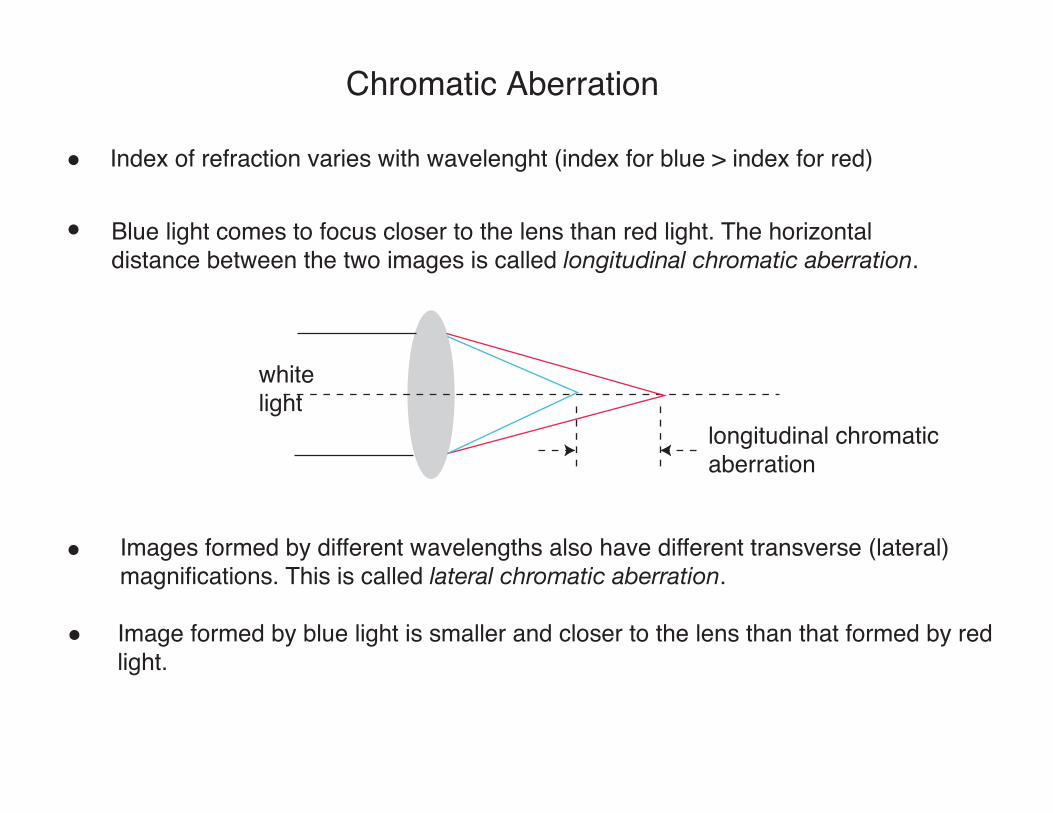
Chromatic Aberration
Index of refraction varies with wavelenght (index for blue > index for red)
Blue light comes to focus closer to the lens than red light. The horizontaldistance between the two images is called longitudinal chromatic aberration.
whitelight
longitudinal chromatic aberration
Images formed by different wavelengths also have different transverse (lateral)magnifications. This is called lateral chromatic aberration.
Image formed by blue light is smaller and closer to the lens than that formed by redlight.

Correcting Chromatic Aberration
Using a combination of two kinds of glasses, crown and flint toform a dichromat. Crown can have more +ve power and has moderate dispersion,while flint can have lower -ve power and has high dispersion.
crown(1)
flint(2)
V = ne "1nF " nC
P1
P2
= V1
V2
P = (n1 "1)( 1R1
" 1R2
) + (n2 "1)( 1R1
" 1R2
)
P = P1 + P2
Set the powers equal for the wavelengths,F, C and e.
(dispersion factoror Abbe's factor)
P1 = P V1
V1 "V2
P2 = "P V2
V1 "V2
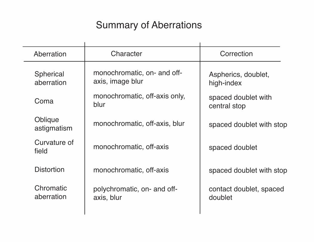
Summary of Aberrations
Aberration Character Correction
Sphericalaberration
monochromatic, on- and off-axis, image blur
Aspherics, doublet,high-index
Coma monochromatic, off-axis only,blur
spaced doublet with central stop
Oblique astigmatism monochromatic, off-axis, blur spaced doublet with stop
Curvature offield monochromatic, off-axis spaced doublet
Distortion monochromatic, off-axis spaced doublet with stop
Chromaticaberration
polychromatic, on- and off-axis, blur
contact doublet, spaceddoublet
Optical Systems
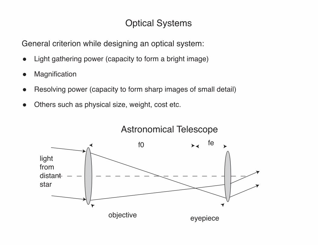
Light gathering power (capacity to form a bright image)
Magnification
Resolving power (capacity to form sharp images of small detail)
Others such as physical size, weight, cost etc.
General criterion while designing an optical system:
Astronomical Telescope
lightfrom distantstar
objective eyepiece
f0 fe
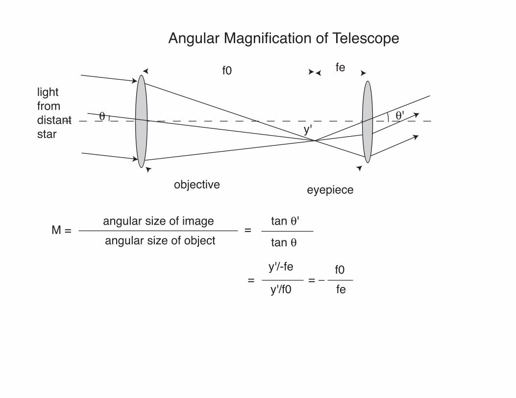
Angular Magnification of Telescope
lightfrom distantstar
objective eyepiece
f0 fe
! !'
M = angular size of imageangular size of object
=tan !tan !'
y'
=y'/-fe
y'/f0= "
f0fe
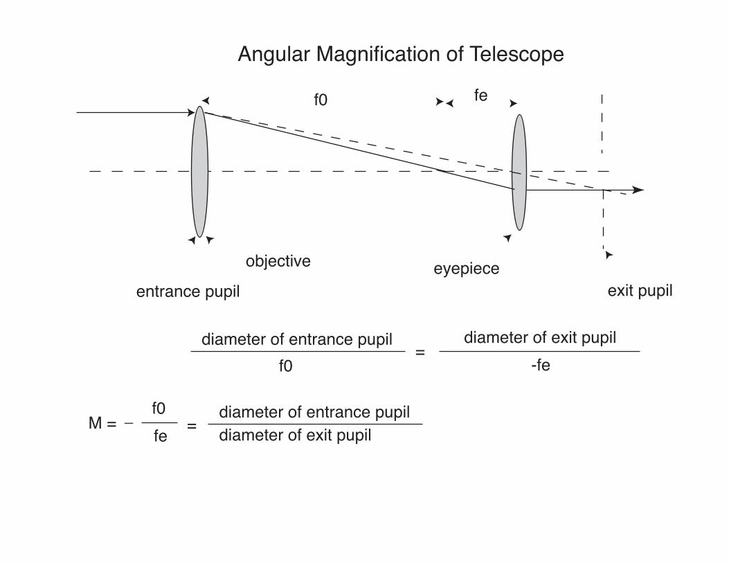
Angular Magnification of Telescope
objective eyepiece
f0 fe
M = "f0fe
entrance pupil exit pupil
diameter of entrance pupil diameter of exit pupilf0 -fe
=
=diameter of entrance pupildiameter of exit pupil
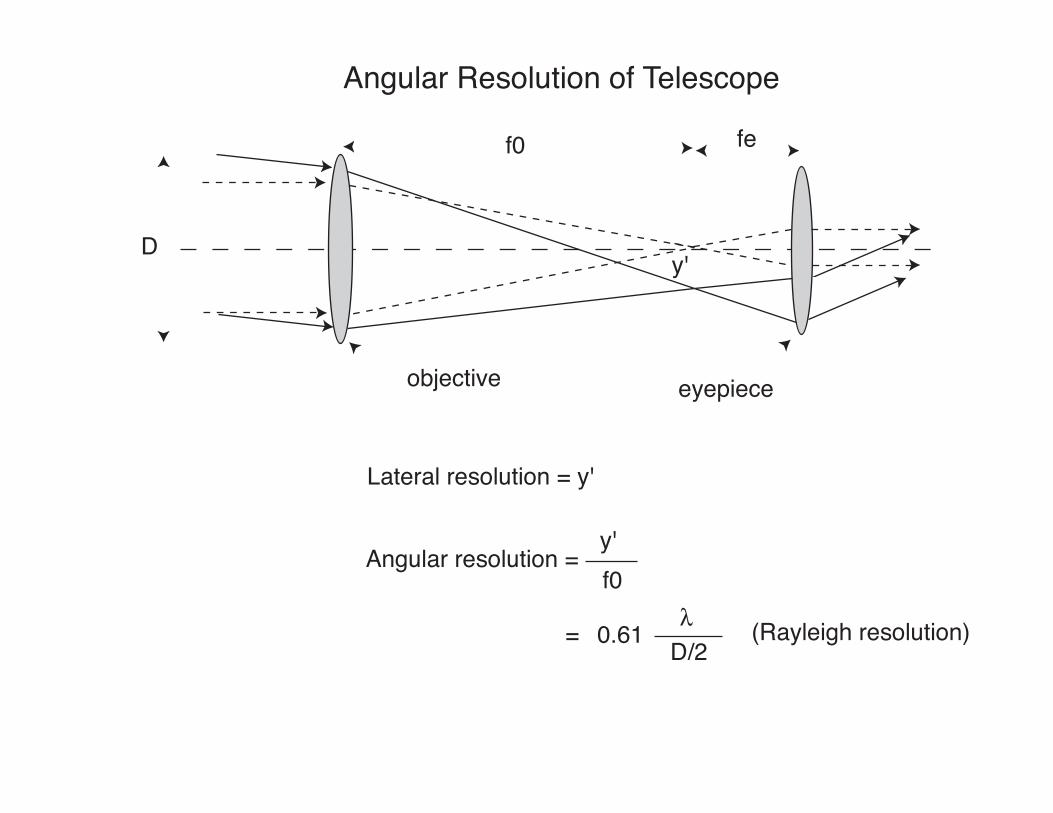
Angular Resolution of Telescope
objective eyepiece
f0 fe
y'
Lateral resolution = y'
Angular resolution =
D
y'f0
= 0.61 #D/2
(Rayleigh resolution)
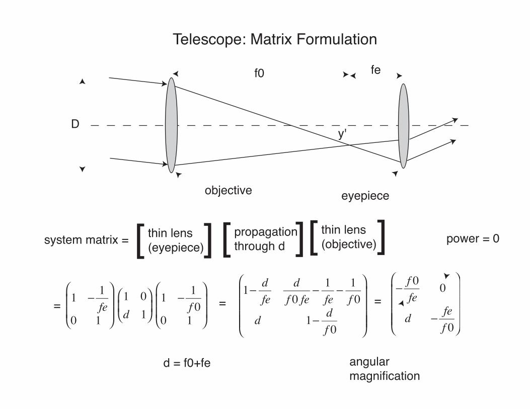
Telescope: Matrix Formulation
objective eyepiece
f0 fe
y'D
system matrix = [ [thin lens (eyepiece) [ [propagation
through d [ [thin lens (objective)
1 " 1fe
0 1
$
%
& &
'
(
) )
1 0d 1
$
% &
'
( )
1 " 1f 0
0 1
$
%
& &
'
(
) ) =
1" dfe
df 0 fe
" 1fe
" 1f 0
d 1" df 0
$
%
& & & &
'
(
) ) ) )
=" f 0fe
0
d " fef 0
$
%
& & & &
'
(
) ) ) )
=
power = 0
angularmagnification
d = f0+fe
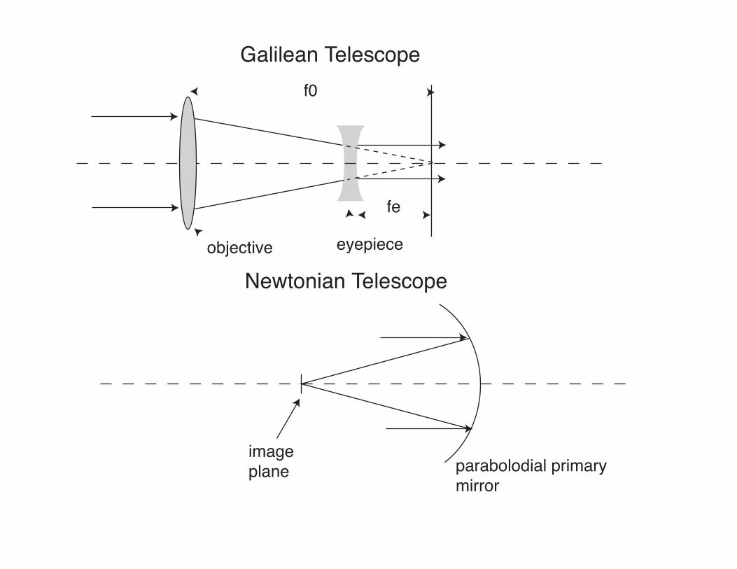
Galilean Telescope
objective eyepiece
f0
fe
Newtonian Telescope
imageplane parabolodial primary
mirror