Tunable negative refraction based on quantum interferencejila negind_aug06.pdf · 1 Tunable...
41
1 Tunable negative refraction based on quantum interference Susanne Yelin Dept. of Physics, University of Connecticut Jürgen Kästel, Michael Fleischhauer TU Kaiserslautern, Germany Ron Walsworth Harvard/Smithsonian CfA Breckenridge, August 25, 2006
Transcript of Tunable negative refraction based on quantum interferencejila negind_aug06.pdf · 1 Tunable...
1
Tunable negative refraction based on quantum
interferenceSusanne Yelin
Dept. of Physics, University of Connecticut
Jürgen Kästel, Michael FleischhauerTU Kaiserslautern, Germany
Ron WalsworthHarvard/Smithsonian CfA
Breckenridge, August 25, 2006

2
Model
θθ’< θ
n=1 n’>1
normal refraction(Snell’s law)
3
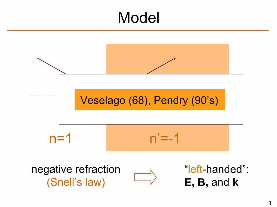
Model
n=1 n’=-1
negative refraction(Snell’s law)
θ θ’= -θ
“left-handed”: E, B, and k
Veselago (68), Pendry (90’s)
4
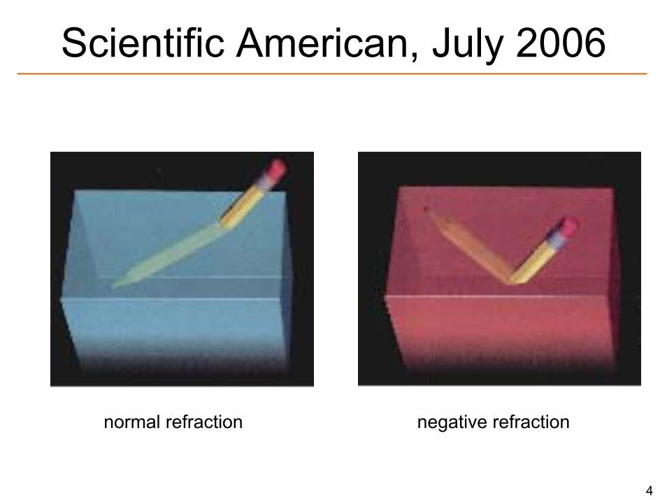
Scientific American, July 2006
normal refraction negative refraction
5
Contents
• Definitions & examples
• Chiral media
• EIT based negative refraction
– Local field effects
– Tunability
• Conclusion
6
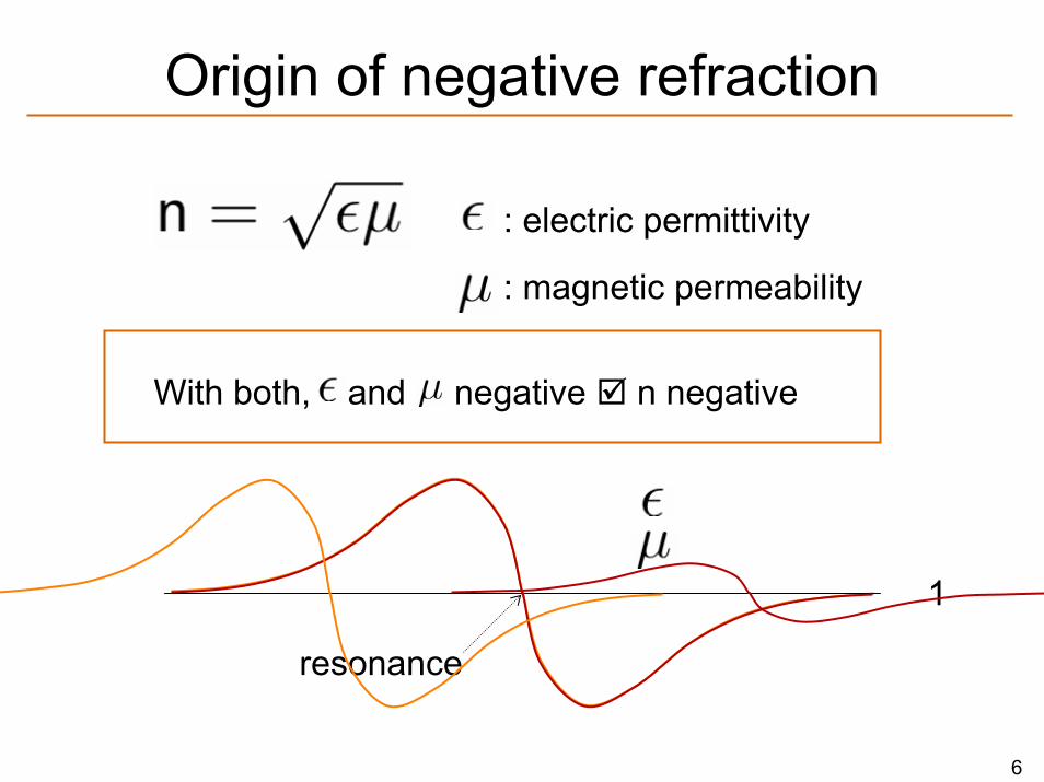
Origin of negative refraction
: electric permittivity
: magnetic permeability
resonance
1
With both, and negative n negative
7
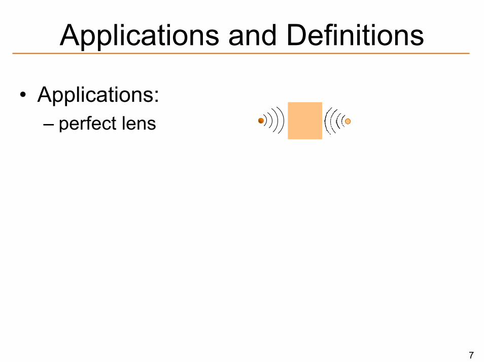
Applications and Definitions
• Applications: – perfect lens– far apart superradiance
8
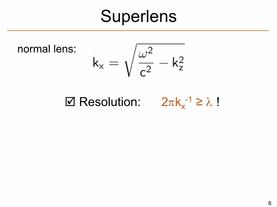
Resolution: 2πkx-1 ≥ λ !
negative refraction:
kz can be imaginary kx > ω/c possible
Superlens
normal lens:
superlens:
9
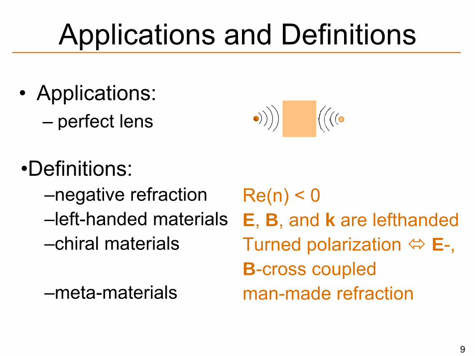
Applications and Definitions
• Applications: – perfect lens– far apart superradiance
Re(n) < 0E, B, and k are lefthandedTurned polarization E-, B-cross coupledman-made refraction
•Definitions:–negative refraction–left-handed materials–chiral materials
–meta-materials
10
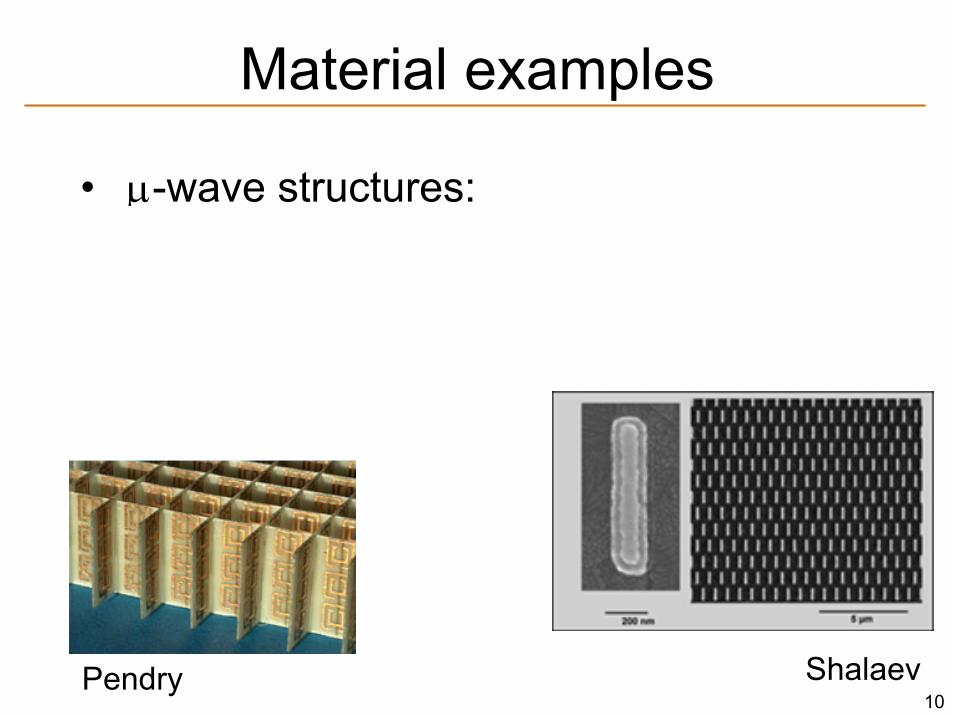
Material examples
• μ-wave structures:– Electric dipole– Magnetic dipole
Choose such that they have the same resonance frequency!
Pendry Shalaev
11
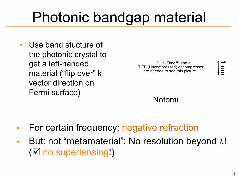
Photonic bandgap material
• Use band stucture of the photonic crystal to get a left-handed material (“flip over” k vector direction on Fermi surface)
QuickTime™ and aTIFF (Uncompressed) decompressor
are needed to see this picture.
1 μm
Notomi
• For certain frequency: negative refraction• But: not “metamaterial”: No resolution beyond λ!
( no superlensing!)
12
Absorption
So far: refraction/absorption ≈ 1…5
Our case: Re(n)/Im(n) = 100
13
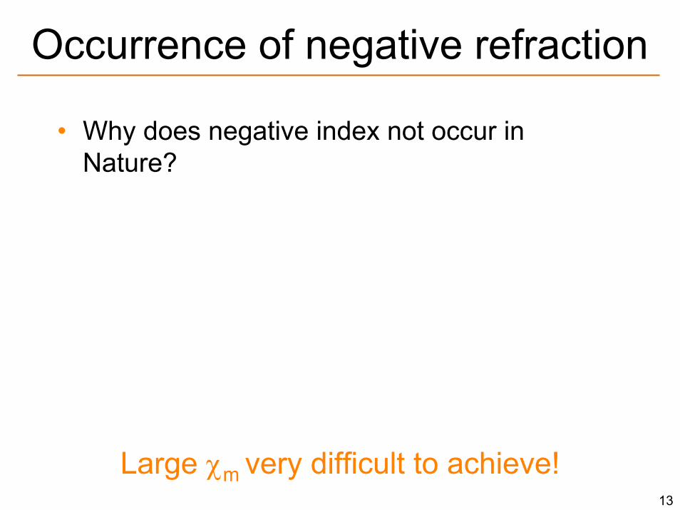
Occurrence of negative refraction
• Why does negative index not occur in Nature?—Absorption (Kramers-Kronig)—Overlapping resonance of ε and μ needed –for n<0:
Large χm very difficult to achieve!
14
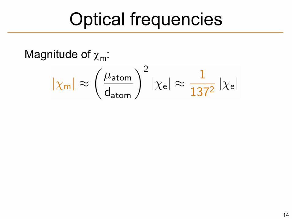
Optical frequencies
Magnitude of χm:
In optical frequencies: Inhomogenous broadening by far outweighs
radiative (M1) linewidth
huge absorption
15
Chiral media (Pendry)
• Remember: • Chiral media: cross coupling between electric
and magnetic fields
• Index of refraction
with
16
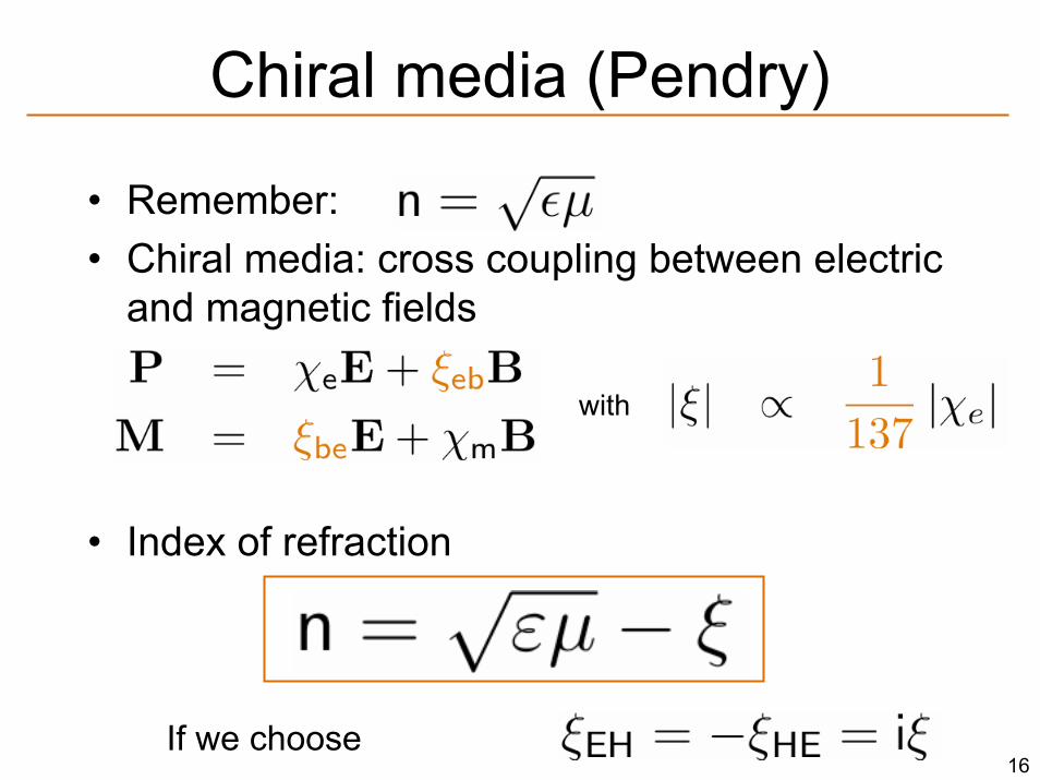
• Remember: • Chiral media: cross coupling between electric
and magnetic fields
• Index of refraction
with
If we choose
Chiral media (Pendry)

17
EIT based negative refraction
V-type system:
• E, B electric/ magnetic part of probe field
• Ω cross couples electric and magnetic transition
Chiral behavior
• γ0 « γ EITB E
Ω
|1
|2 |3γ0 γ
absorption (χe”)
dispersion (χe’)
18
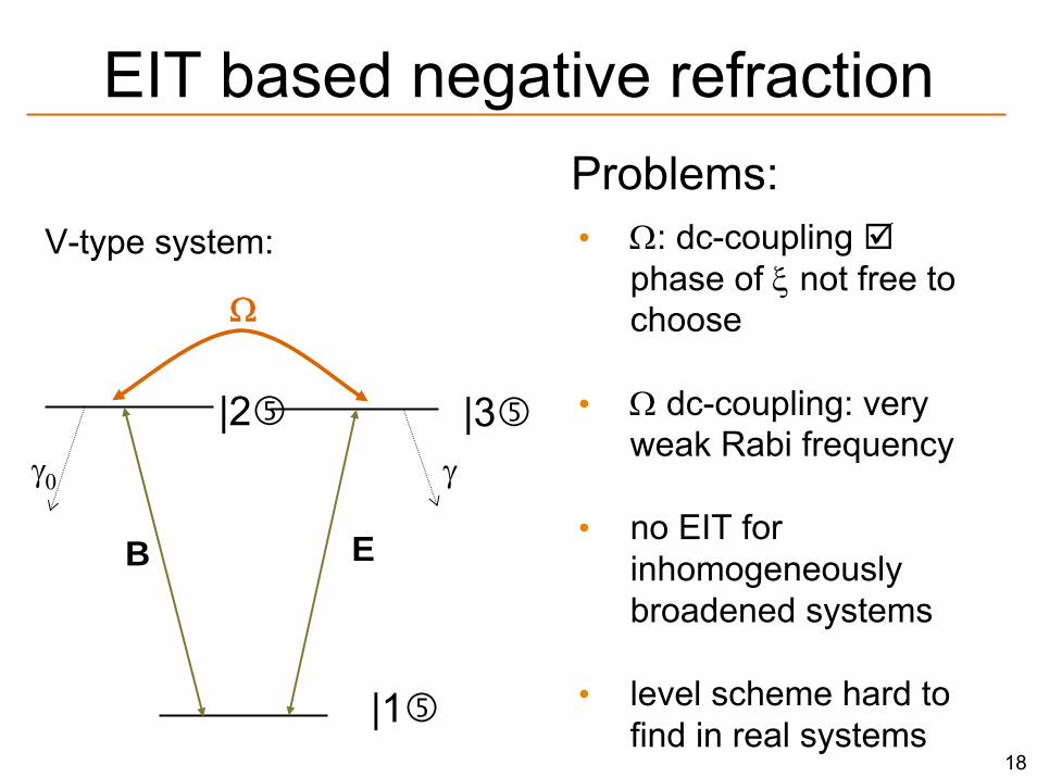
EIT based negative refraction
V-type system:
B E
Ω
|1
|2 |3γ0 γ
• Ω: dc-coupling phase of ξ not free to choose
• Ω dc-coupling: very weak Rabi frequency
• no EIT for inhomogeneouslybroadened systems
• level scheme hard to find in real systems
Problems:
19
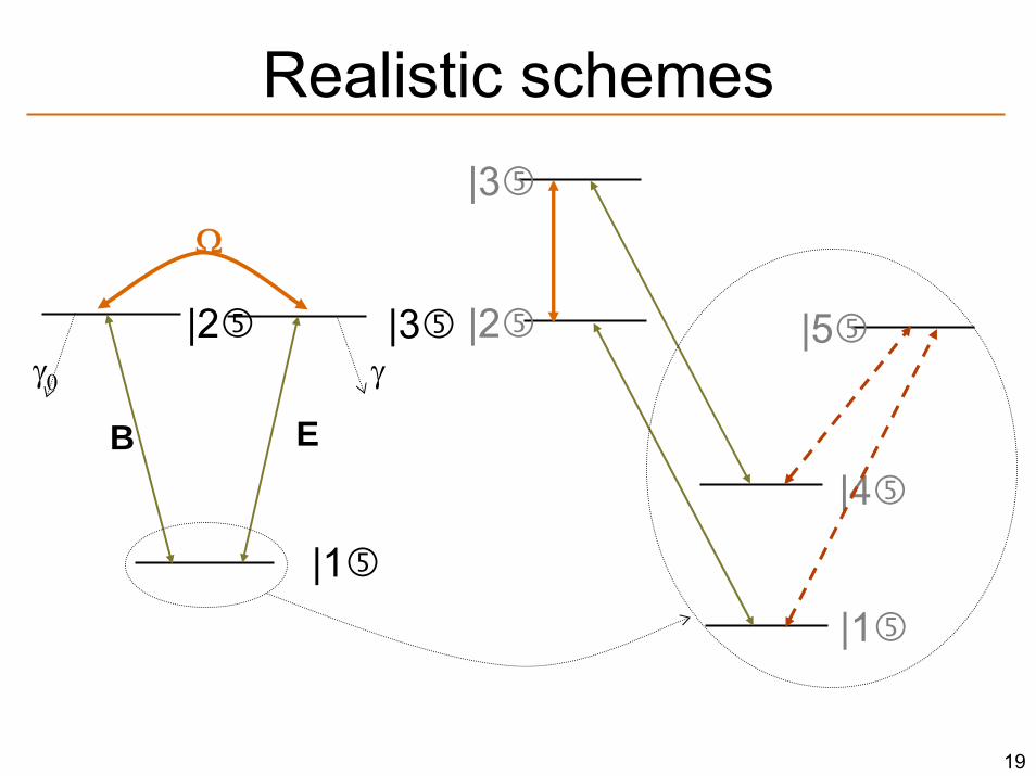
Realistic schemes
B E
Ω
|1
|2 |3γ0 γ
|4
|1
|5
|3
|2
20
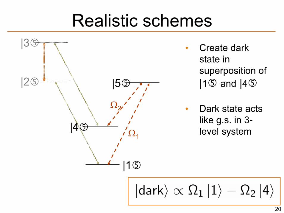
Realistic schemes• Create dark
state in superposition of |1 and |4
• Dark state acts like g.s. in 3-level system|4
|1
|5
|3
|2
Ω1
Ω2
21
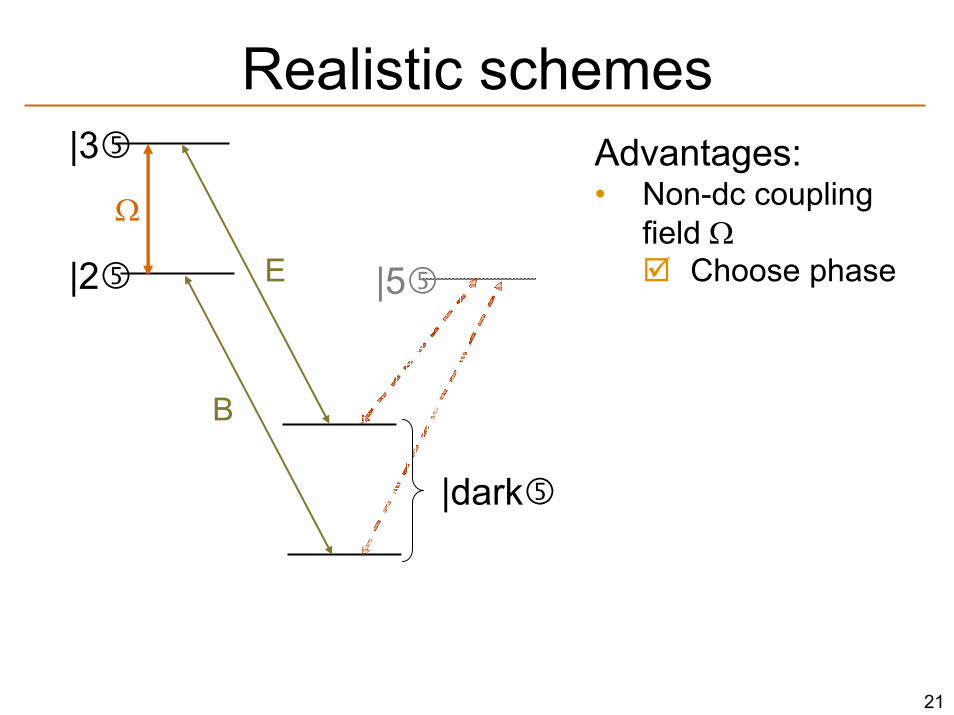
Realistic schemes
|dark
|5
|3
|2
B
E
Advantages:• Non-dc coupling
field ΩChoose phase
Ω
22
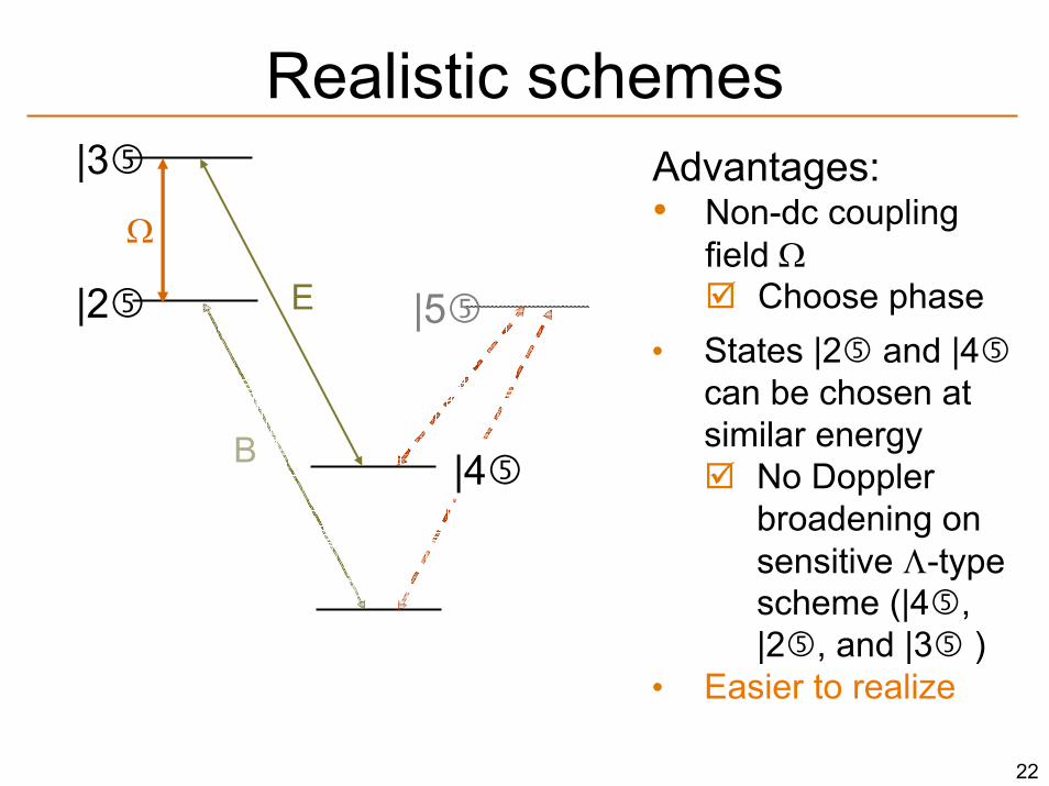
Realistic schemes
|5
|3
|2
B
E
Ω
Advantages:• Non-dc coupling
field ΩChoose phase
|4
• States |2 and |4can be chosen at similar energy
No Doppler broadening on sensitive Λ-type scheme (|4 , |2 , and |3 )
• Easier to realize
23
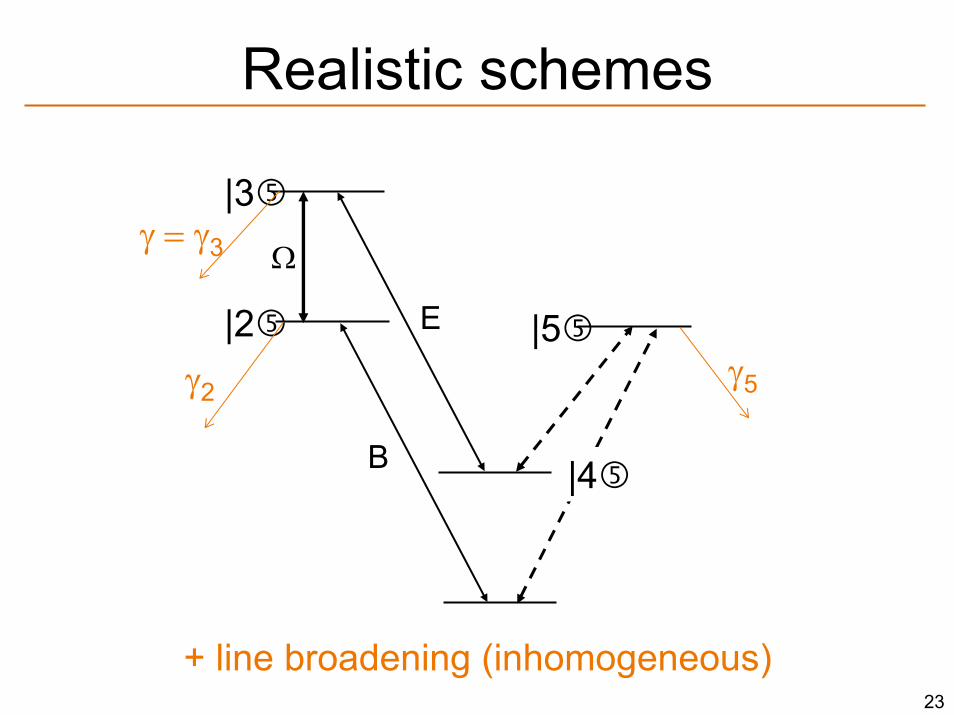
Realistic schemes
|5
|3
|2
B
E
Ω
|4
γ = γ3
γ2γ5
+ line broadening (inhomogeneous)
24
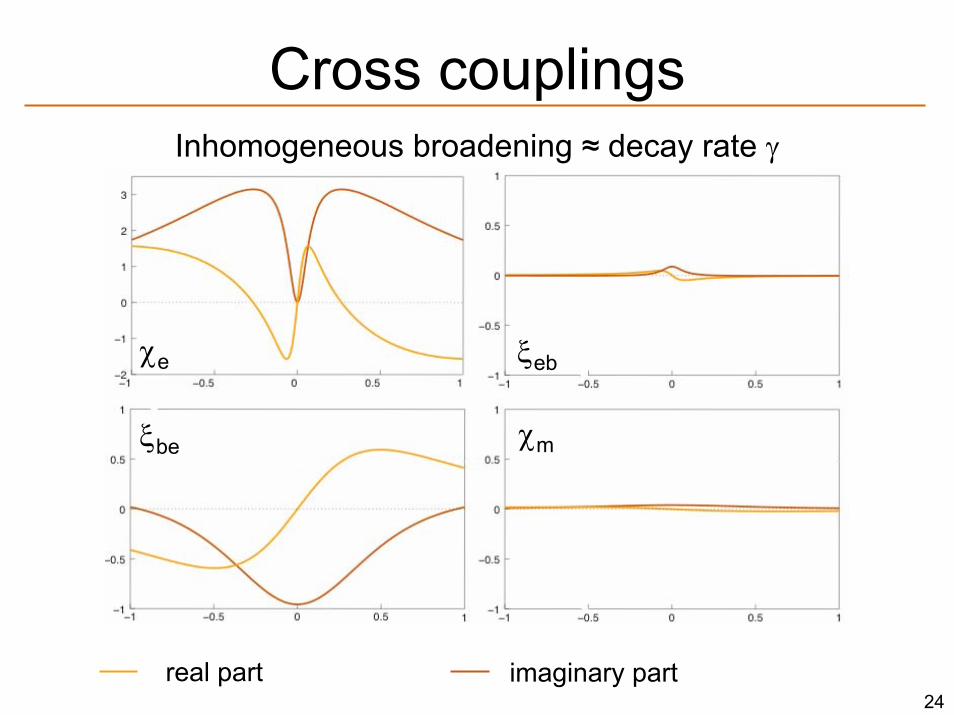
Cross couplings
χmξbe
ξebχe
real part imaginary part
Inhomogeneous broadening ≈ decay rate γ
25
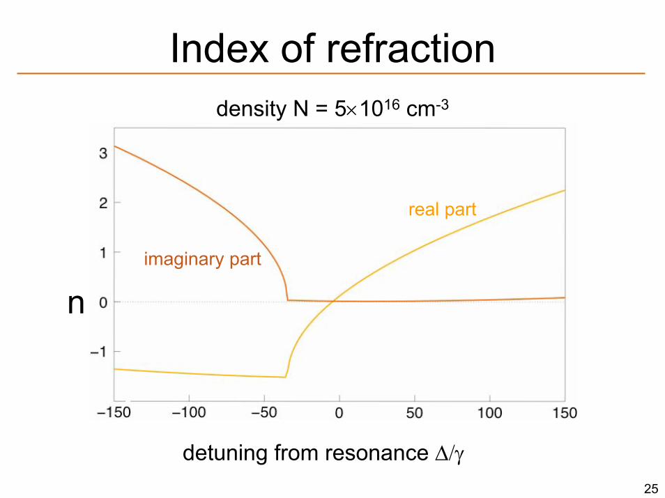
Index of refraction
n
real part
imaginary part
density N = 5×1016 cm-3
detuning from resonance Δ/γ
26
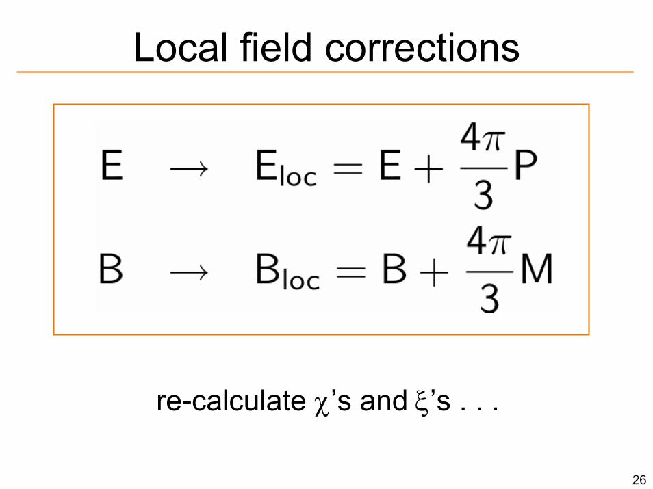
Local field corrections
re-calculate χ’s and ξ’s . . .
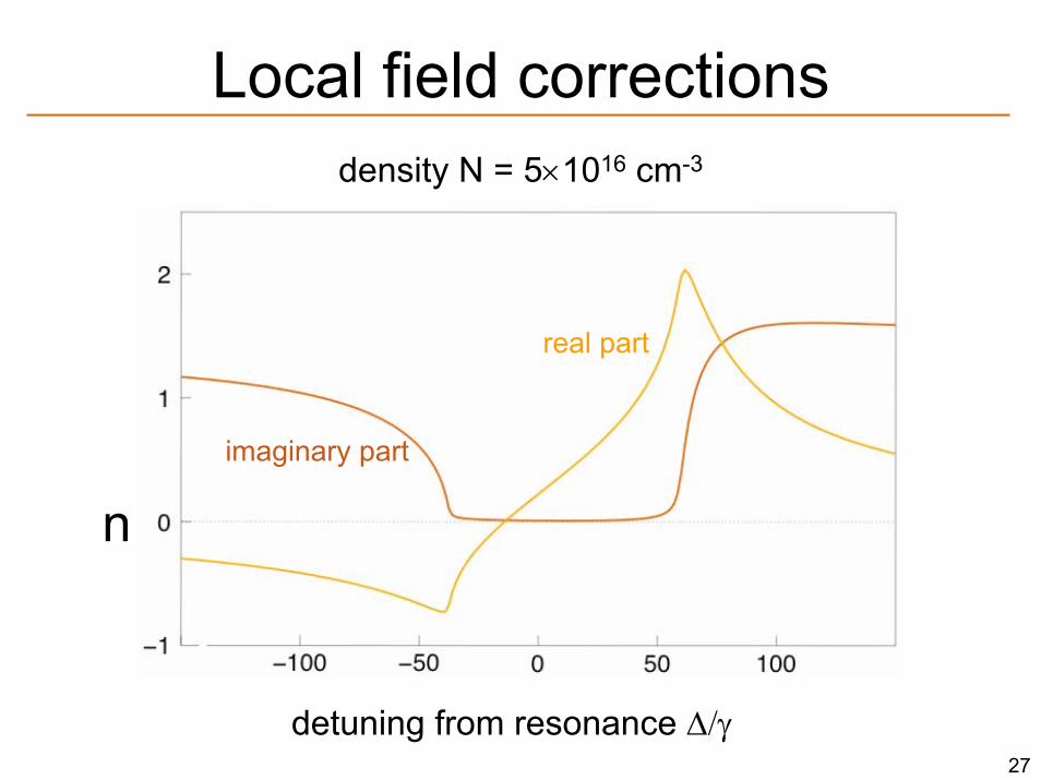
27
Local field corrections
n
detuning from resonance Δ/γ
real part
imaginary part
density N = 5×1016 cm-3
28
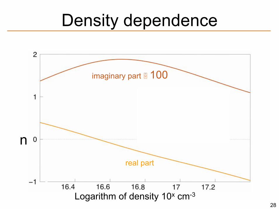
Density dependence
n
Logarithm of density 10x cm-3
real part
imaginary part 100
Re(n)/Im(n)
log 1
0
29
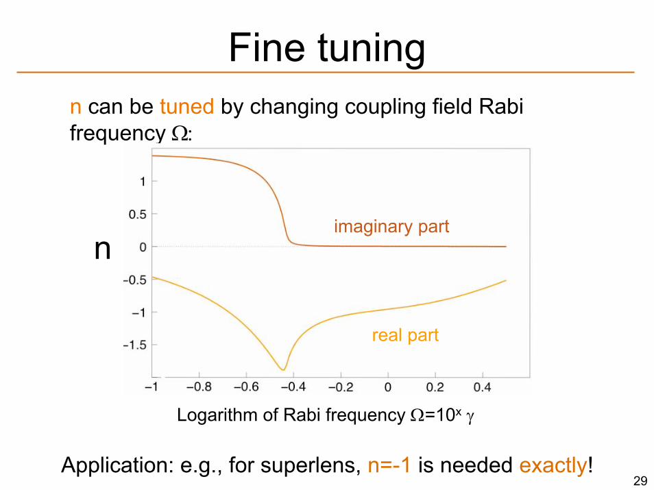
Fine tuningn can be tuned by changing coupling field Rabi frequency Ω:
Application: e.g., for superlens, n=-1 is needed exactly!
n
real part
imaginary part
Logarithm of Rabi frequency Ω=10x γ

30
Realization schemes
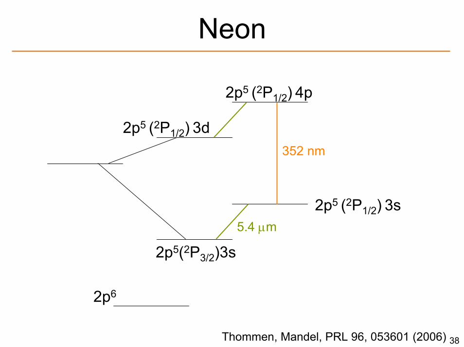
• Atoms: e.g. Neon
• Molecules: Use different rotational levels for different parities
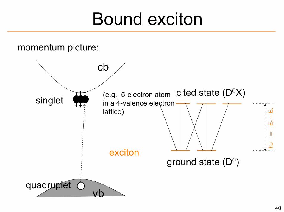
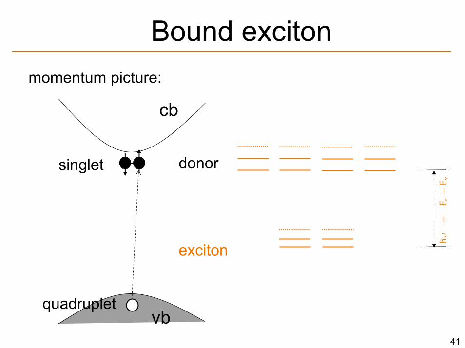
• Bound excitons: use D0 states with different parities for lower, and D0X states with different parities for upper states.
31
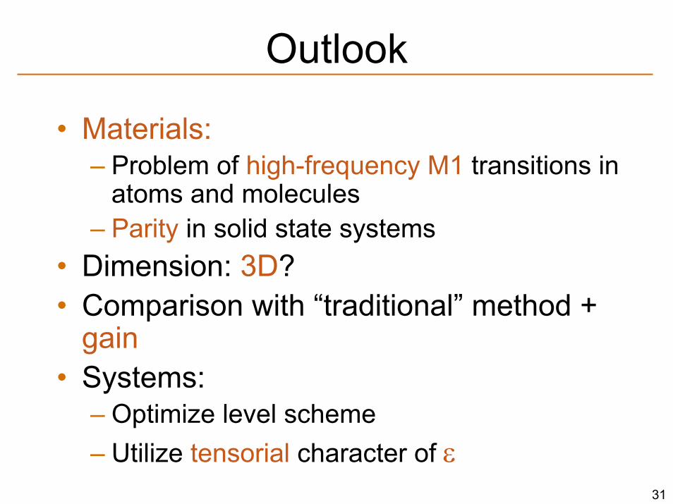
Outlook
• Materials:– Problem of high-frequency M1 transitions in
atoms and molecules– Parity in solid state systems
• Dimension: 3D?• Comparison with “traditional” method +
gain• Systems:
– Optimize level scheme – Utilize tensorial character of ε

32
33
Conclusions
• Use of negative refraction:– superlenses and others
• Metamaterials:– chiral media for presence of cross coupling– EIT for suppression of absorption– energy and Rabi freq. of coupling fields for
tuning
34
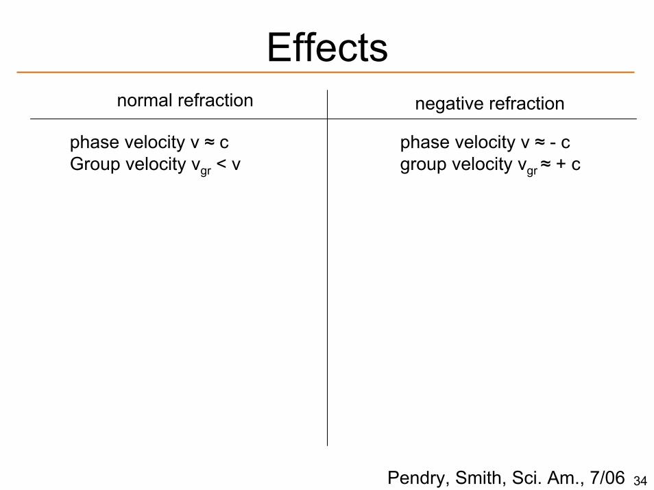
Effects
Pendry, Smith, Sci. Am., 7/06
normal refraction negative refraction
phase velocity v ≈ cGroup velocity vgr < v
phase velocity v ≈ - cgroup velocity vgr ≈ + c
Cerenkov radiation:forward cone backward cone
Doppler effect:approaching objectblue shifted red shifted

35
Problem: absorption
Kramers - Kronig:relationship between refraction/absorption
large χe’ (refraction) large χe” (absorption)

36
Cross couplings
Solve for α . . .
macroscopic picture:atomic picture:

37
Different approach
• usual problem: μ (χm)• Instead: leave μ and make ε into tensor
(“geometric approach”)
S Poynting vector
k wave vector
0
normalbirefringent“very birefringent”
Podolskiy, Narimanov, PRB R201101, (2005)
Disadvantage: works only in waveguide (i.e. 1D)
38
2p5 (2P1/2) 3d
2p5 (2P1/2) 4p
2p5 (2P1/2) 3s
2p5(2P3/2)3s
2p6
352 nm
5.4 μm
Neon
Thommen, Mandel, PRL 96, 053601 (2006)
39
. . .
. . .
. . .
. . .
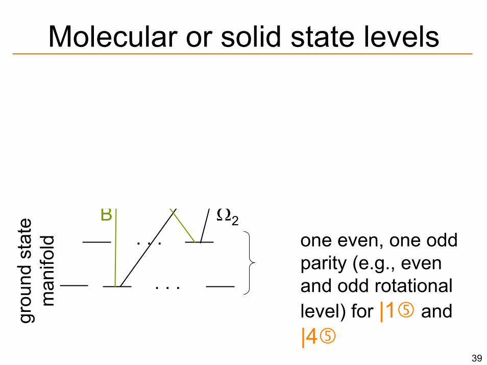
one even, one odd parity (e.g., even and odd rotational level) for |1 and |4
one even, two odd parity states (P(|2 )= P(|1 ))
exci
ted
man
ifold
grou
nd s
tate
m
anifo
ldMolecular or solid state levels
Ω
BE
Ω1
Ω2
40
Bound exciton
excited state (D0X)
ground state (D0)
momentum picture:
cb
vb
donorsinglet
quadruplet
exciton
(e.g., 5-electron atomin a 4-valence electronlattice)
41
Bound excitonmomentum picture:
cb
vb
donorsinglet
quadruplet
exciton