Modeling of Finite State Machinesdebdeep/teaching/VLSI/slides/fsm.pdf · Coding Styles • Johnson:...
36
Modeling of Finite State Machines Debdeep Mukhopadhyay
Transcript of Modeling of Finite State Machinesdebdeep/teaching/VLSI/slides/fsm.pdf · Coding Styles • Johnson:...
Modeling of Finite State Machines
Debdeep Mukhopadhyay
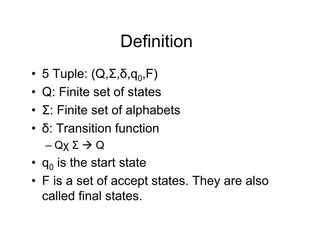
Definition
• 5 Tuple: (Q,Σ,δ,q0,F)• Q: Finite set of states• Σ: Finite set of alphabets• δ: Transition function
– Qχ Σ Q• q0 is the start state• F is a set of accept states. They are also
called final states.
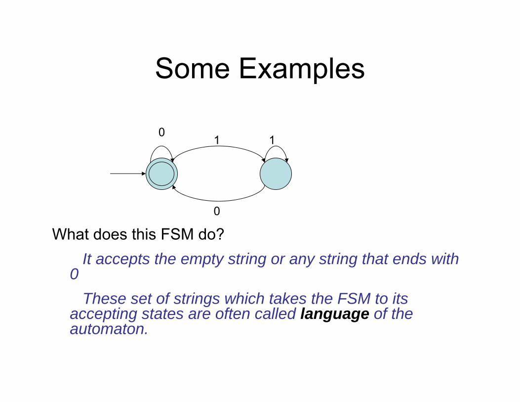
Some Examples
1
What does this FSM do?It accepts the empty string or any string that ends with
0These set of strings which takes the FSM to its
accepting states are often called language of the automaton.
01
0
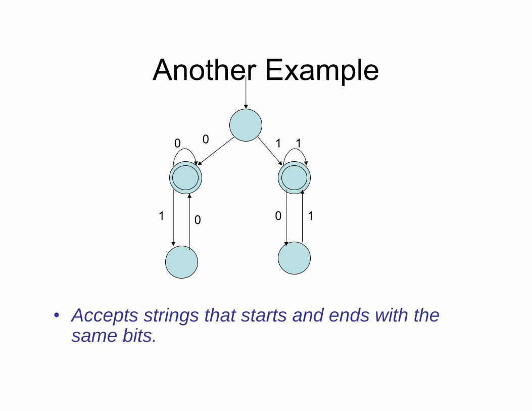
Another Example
• Accepts strings that starts and ends with the same bits.
10
1
0 1
1 0 0

A more complicated example
• FSM accepts if the running sum of the input strings is a multiple of 3.
• RESET symbol resets the running sum to 0.
q0
2
2,<RESET>
2
q1
q2
0,<RESET> 1
1,<RESET>
0
01

Designing FSMs
• Its an art.• Pretend to be an FSM and imagine the
strings are coming one by one.• Remember that there are finite states.• So, you cannot store the entire string, but
only crucial information.• Also, you do not know when the string
ends, so you should always be ready with an answer.
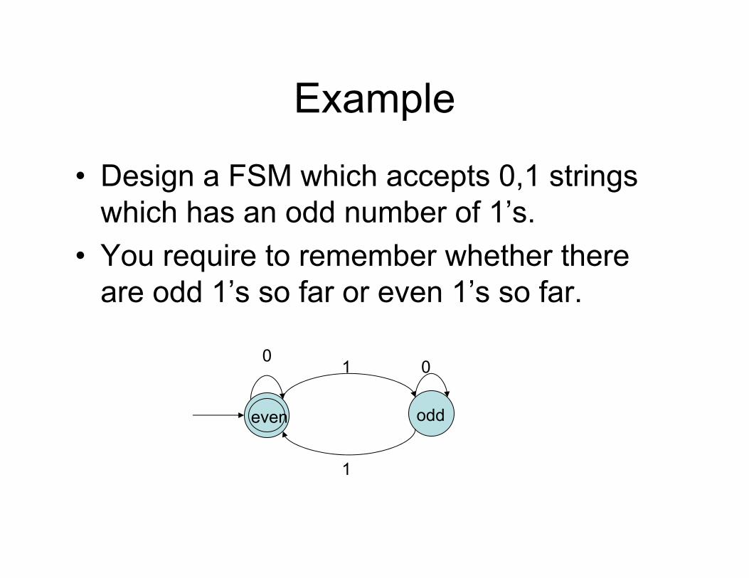
Example
• Design a FSM which accepts 0,1 strings which has an odd number of 1’s.
• You require to remember whether there are odd 1’s so far or even 1’s so far.
00
1
1
even odd
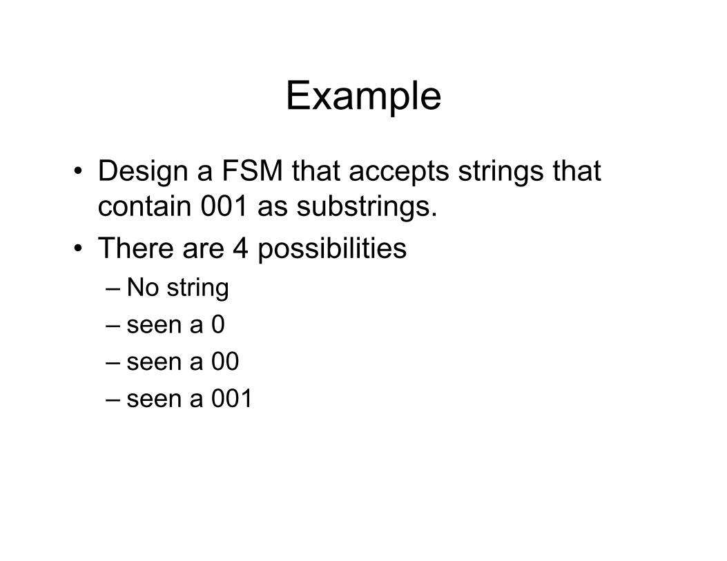
Example
• Design a FSM that accepts strings that contain 001 as substrings.
• There are 4 possibilities– No string– seen a 0– seen a 00– seen a 001
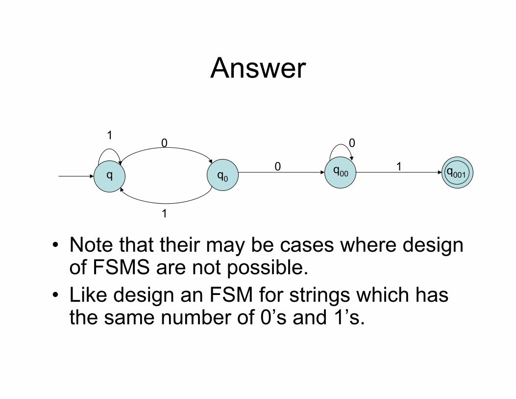
Answer
• Note that their may be cases where design of FSMS are not possible.
• Like design an FSM for strings which has the same number of 0’s and 1’s.
10
1
q q00 1
0
q00 q001
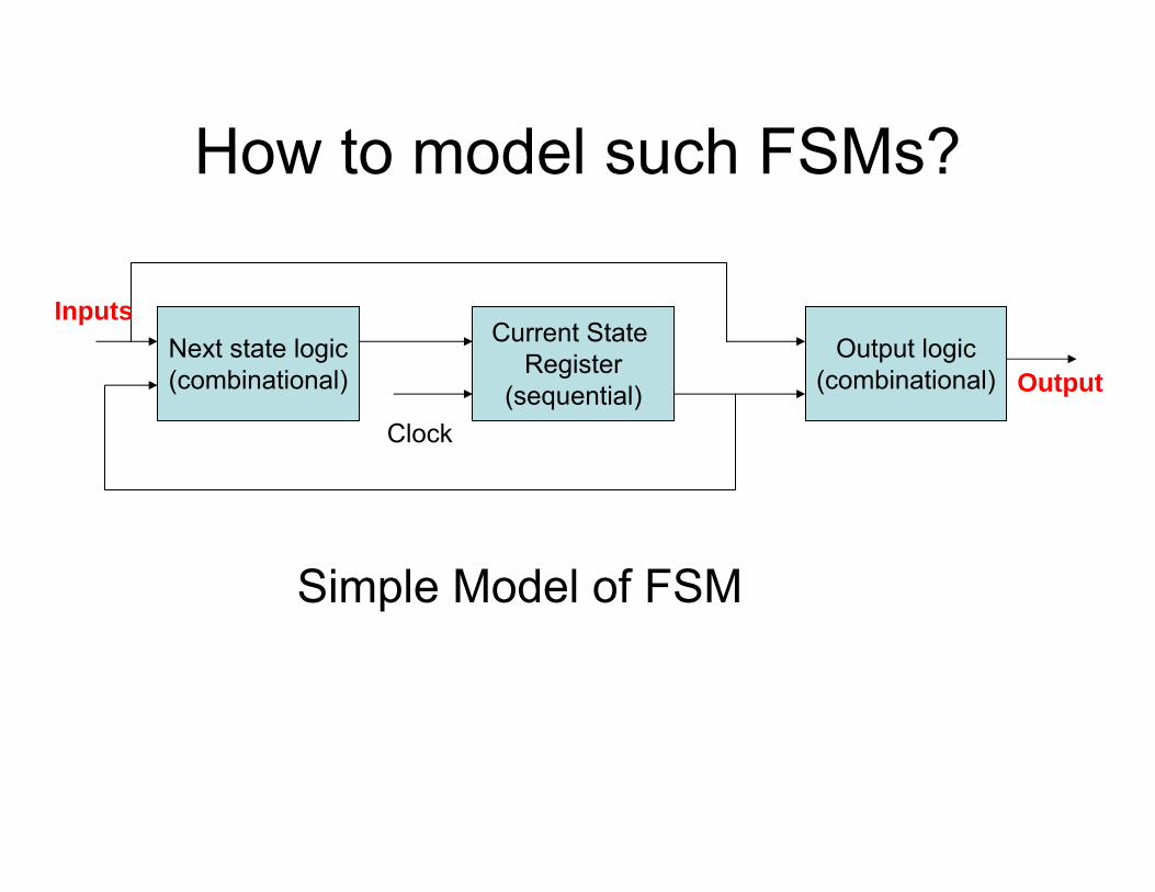
How to model such FSMs?
Simple Model of FSM
Next state logic(combinational)
Current State Register
(sequential)
Output logic(combinational)
Clock
Output
Inputs
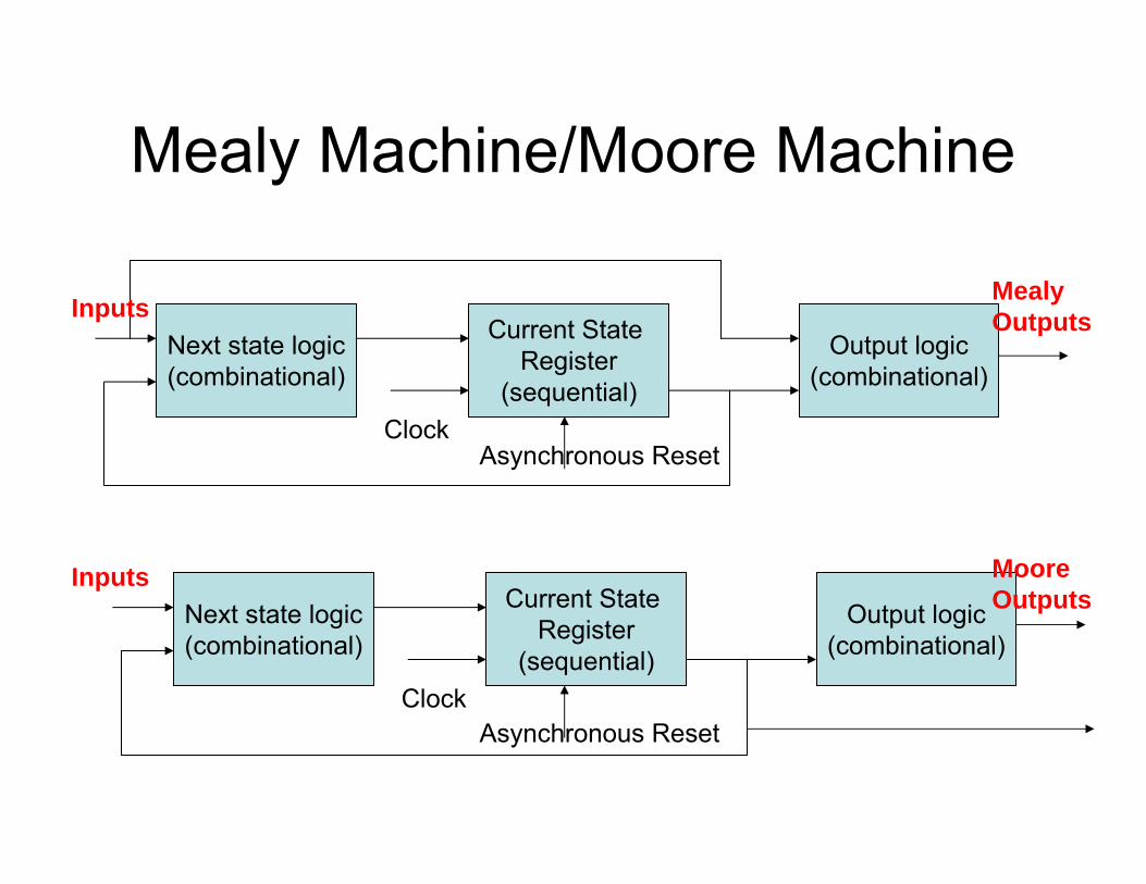
Mealy Machine/Moore Machine
Next state logic(combinational)
Current State Register
(sequential)
Output logic(combinational)
Clock
Mealy OutputsInputs
Next state logic(combinational)
Current State Register
(sequential)
Output logic(combinational)
Clock
Moore Outputs
Inputs
Asynchronous Reset
Asynchronous Reset
Modeling FSMs using Verilog
Issues
• State Encoding– sequential– gray– Johnson– one-hot
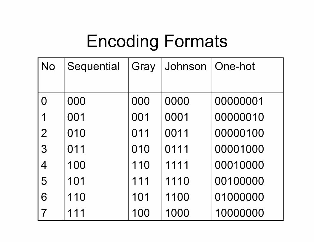
Encoding Formats
0000000100000010000001000000100000010000001000000100000010000000
00000001001101111111111011001000
000001011010110111101100
000001010011100101110111
01234567
One-hotJohnsonGraySequentialNo
Comments on the coding styles
• Binary: Good for arithmetic operations. But may have more transitions, leading to more power consumptions. Also prone to error during the state transitions.
• Gray: Good as they reduce the transitions, and hence consume less dynamic power. Also, can be handy in detecting state transition errors.
Coding Styles
• Johnson: Also there is one bit change, and can be useful in detecting errors during transitions. More bits are required, increases linearly with the number of states. There are unused states, so we require either explicit asynchronous reset or recovery from illegal states (even more hardware!)
• One-hot: yet another low power coding style, requires more no of bits. Useful for describing bus protocols.
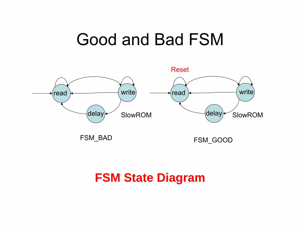
Good and Bad FSM
FSM State Diagram
read write
delay
read write
delay
FSM_BAD FSM_GOOD
Reset
SlowROM SlowROM
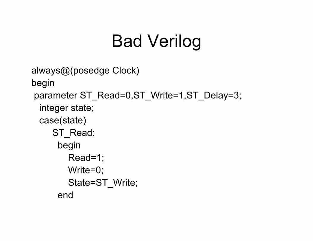
Bad Verilogalways@(posedge Clock)beginparameter ST_Read=0,ST_Write=1,ST_Delay=3;integer state;case(state)
ST_Read:begin
Read=1;Write=0;State=ST_Write;
end
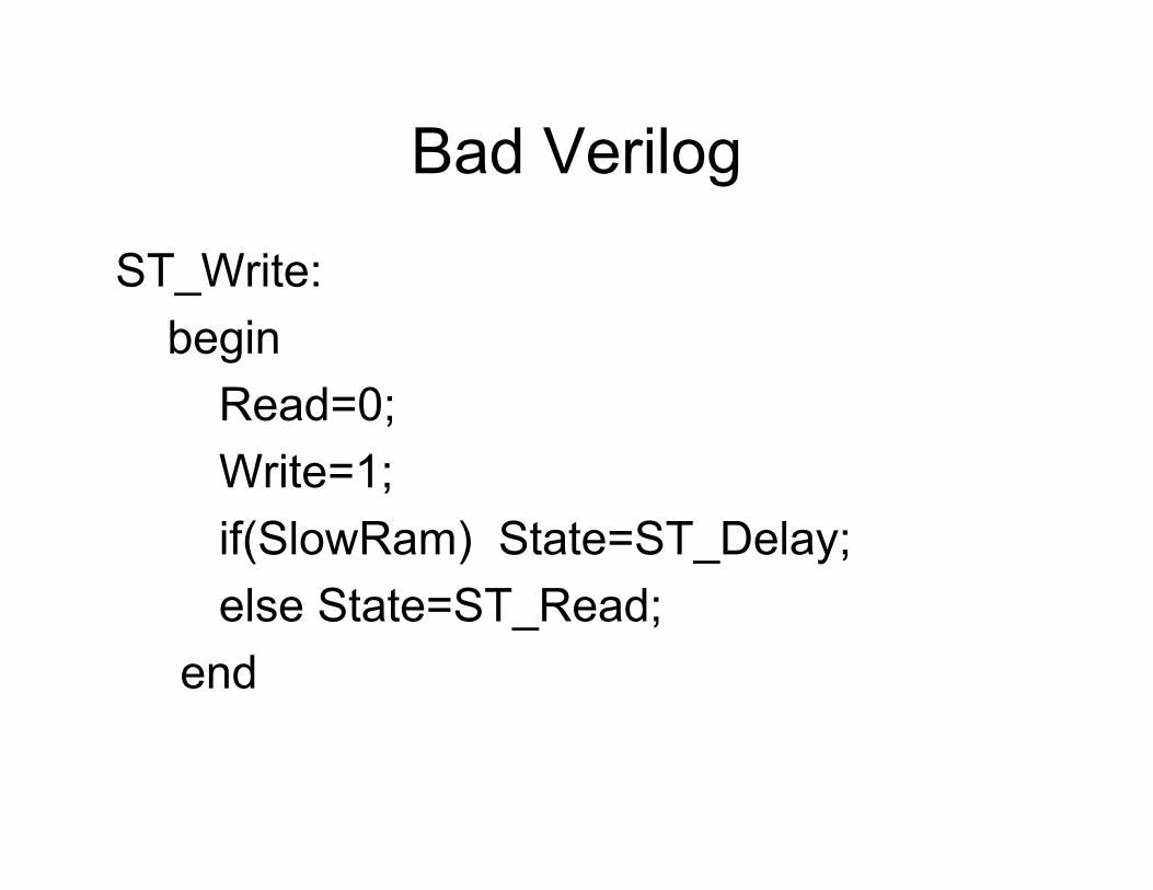
Bad Verilog
ST_Write:begin
Read=0;Write=1;if(SlowRam) State=ST_Delay;else State=ST_Read;
end
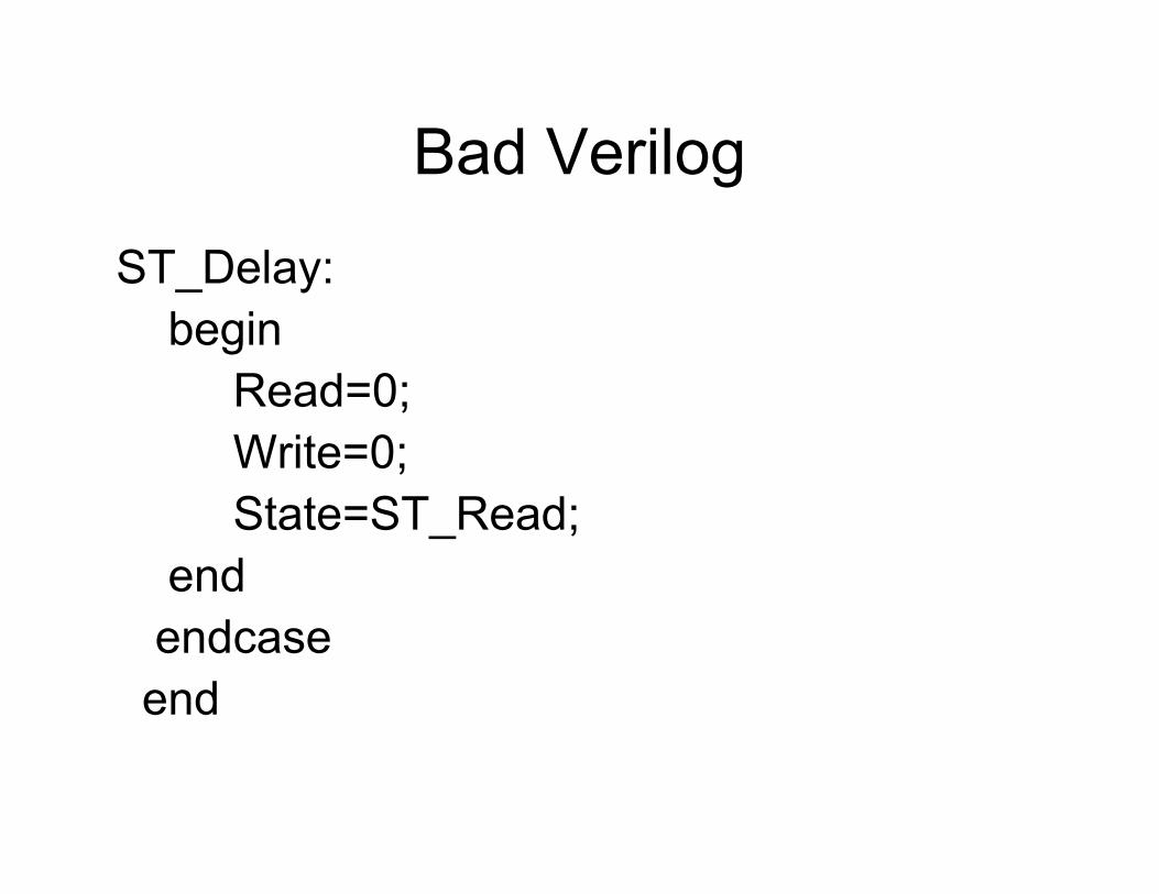
Bad Verilog
ST_Delay:begin
Read=0;Write=0;State=ST_Read;
endendcaseend
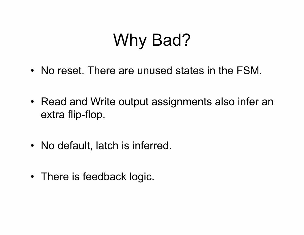
Why Bad?
• No reset. There are unused states in the FSM.
• Read and Write output assignments also infer an extra flip-flop.
• No default, latch is inferred.
• There is feedback logic.
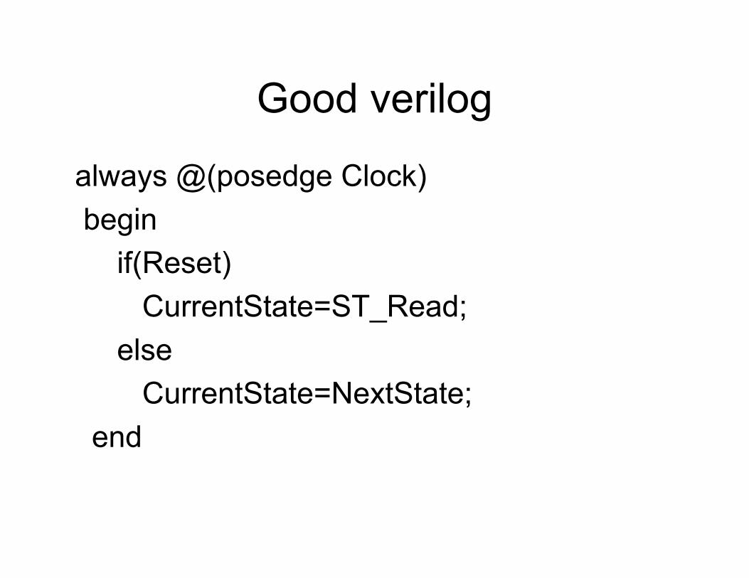
Good verilog
always @(posedge Clock)begin
if(Reset)CurrentState=ST_Read;
elseCurrentState=NextState;
end
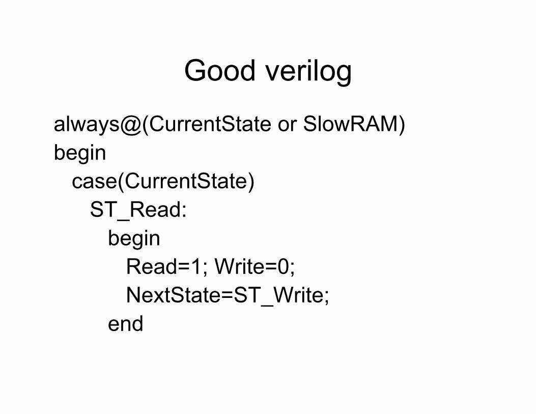
Good verilog
always@(CurrentState or SlowRAM)begin
case(CurrentState)ST_Read:
beginRead=1; Write=0; NextState=ST_Write;
end
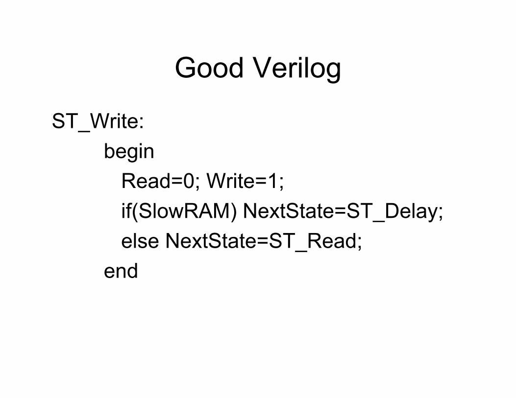
Good Verilog
ST_Write: begin
Read=0; Write=1; if(SlowRAM) NextState=ST_Delay;else NextState=ST_Read;
end

Good VerilogST_Delay:
beginRead=0; Write=0; NextState=ST_Read;
enddefault:
beginRead=0; Write=0; NextState=ST_Read;
endendcase
end
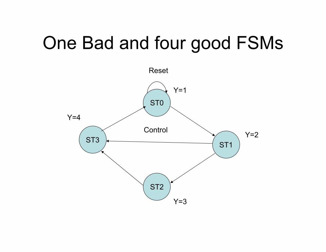
One Bad and four good FSMs
ST0
ST3ST1
ST2
Reset
Y=1
Y=2
Y=3
Y=4
Control
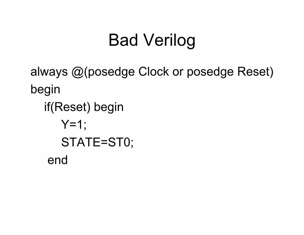
Bad Verilog
always @(posedge Clock or posedge Reset)begin
if(Reset) beginY=1;STATE=ST0;
end
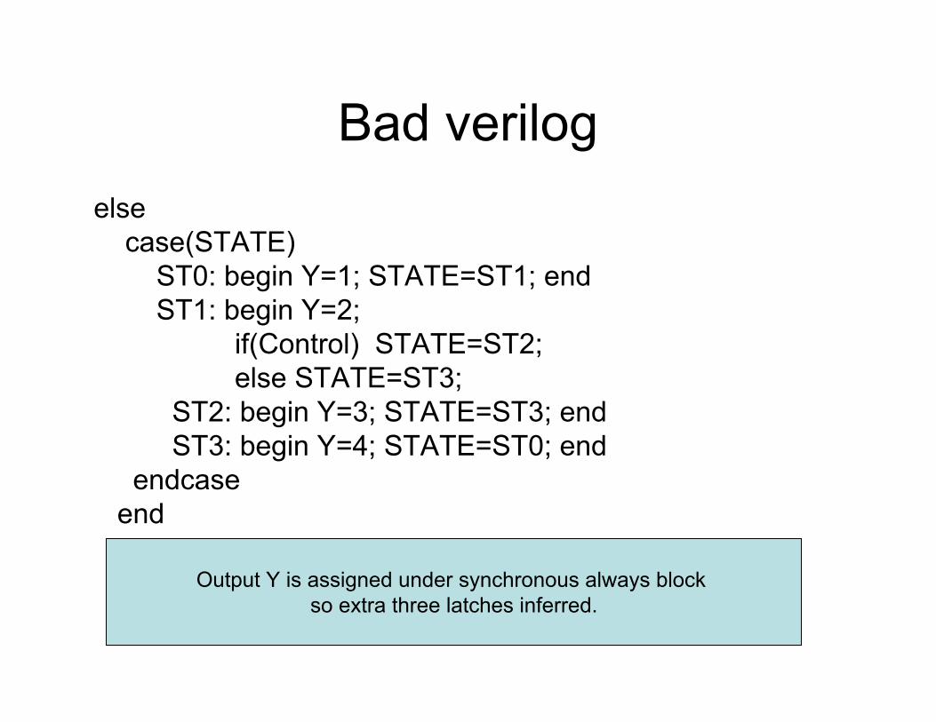
Bad verilogelse
case(STATE)ST0: begin Y=1; STATE=ST1; endST1: begin Y=2;
if(Control) STATE=ST2;else STATE=ST3;
ST2: begin Y=3; STATE=ST3; endST3: begin Y=4; STATE=ST0; end
endcaseend
Output Y is assigned under synchronous always block so extra three latches inferred.
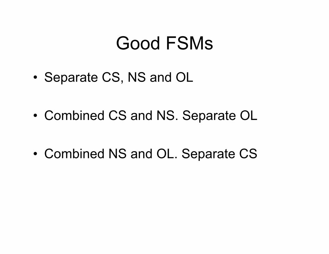
Good FSMs
• Separate CS, NS and OL
• Combined CS and NS. Separate OL
• Combined NS and OL. Separate CS
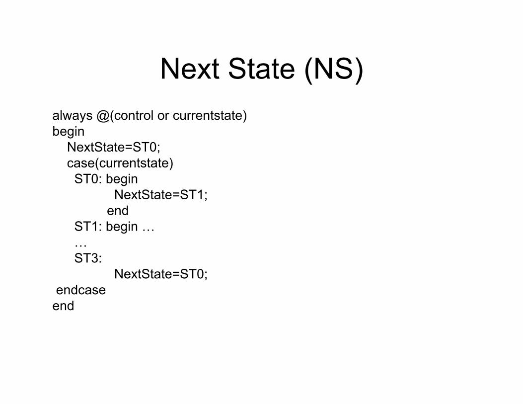
Next State (NS) always @(control or currentstate)begin
NextState=ST0;case(currentstate)ST0: begin
NextState=ST1;end
ST1: begin ……ST3:
NextState=ST0;endcase
end
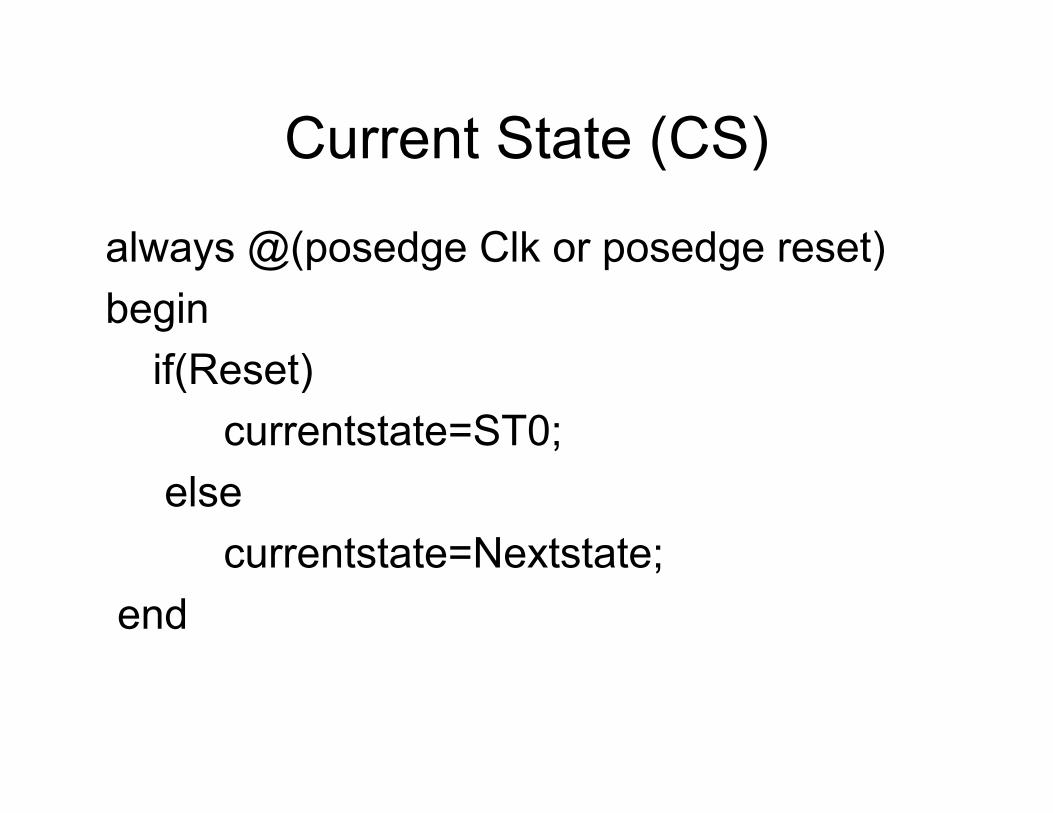
Current State (CS)
always @(posedge Clk or posedge reset)begin
if(Reset)currentstate=ST0;
elsecurrentstate=Nextstate;
end
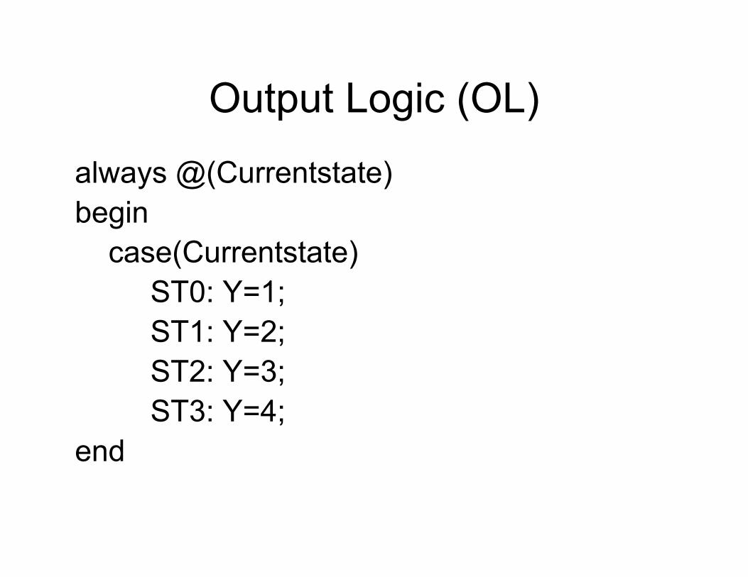
Output Logic (OL)
always @(Currentstate)begin
case(Currentstate)ST0: Y=1;ST1: Y=2;ST2: Y=3;ST3: Y=4;
end

CS+NSalways@(posedge Clock or posedge reset)begin
if(Reset)State=ST0;
elsecase(STATE)
ST0: State=ST1;ST1: if(Control) …ST2: …ST3: STATE=ST0;
endcaseend
default not required as it is in edge triggered
always statement
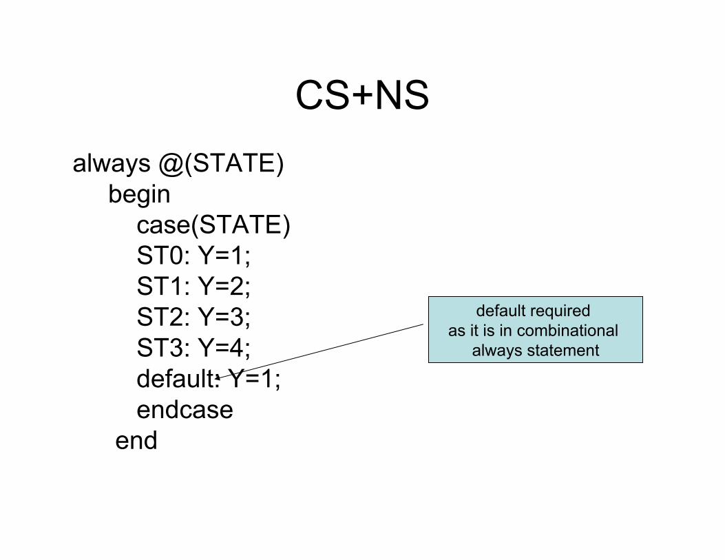
CS+NSalways @(STATE)
begincase(STATE)ST0: Y=1;ST1: Y=2;ST2: Y=3;ST3: Y=4;default: Y=1;endcase
end
default required as it is in combinational
always statement
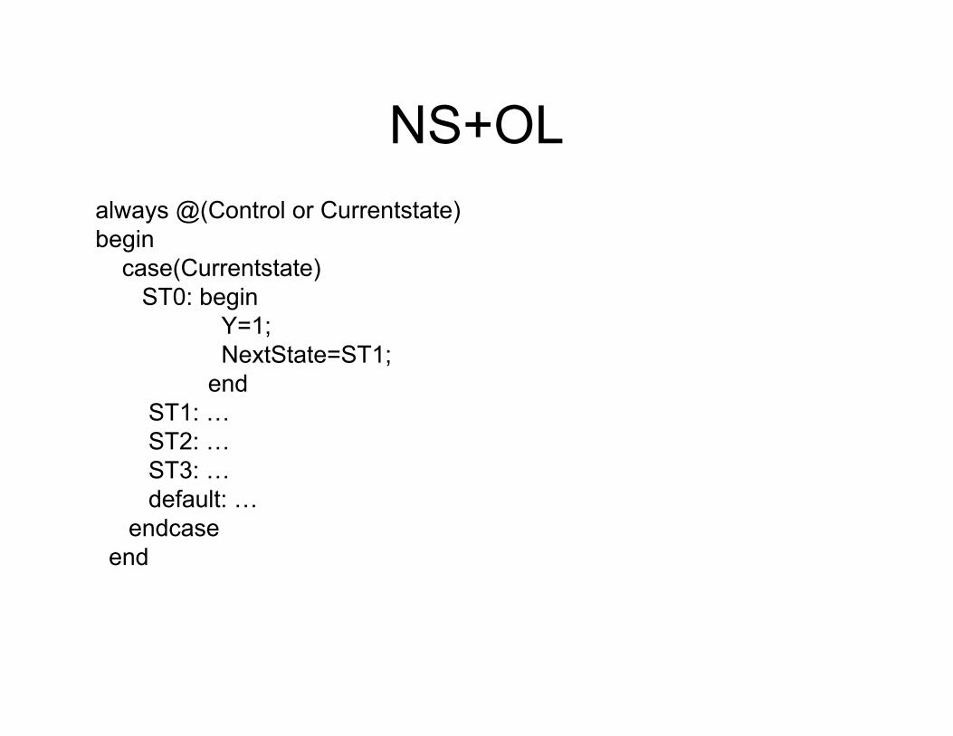
NS+OLalways @(Control or Currentstate)begin
case(Currentstate)ST0: begin
Y=1;NextState=ST1;
endST1: …ST2: …ST3: …default: …
endcaseend
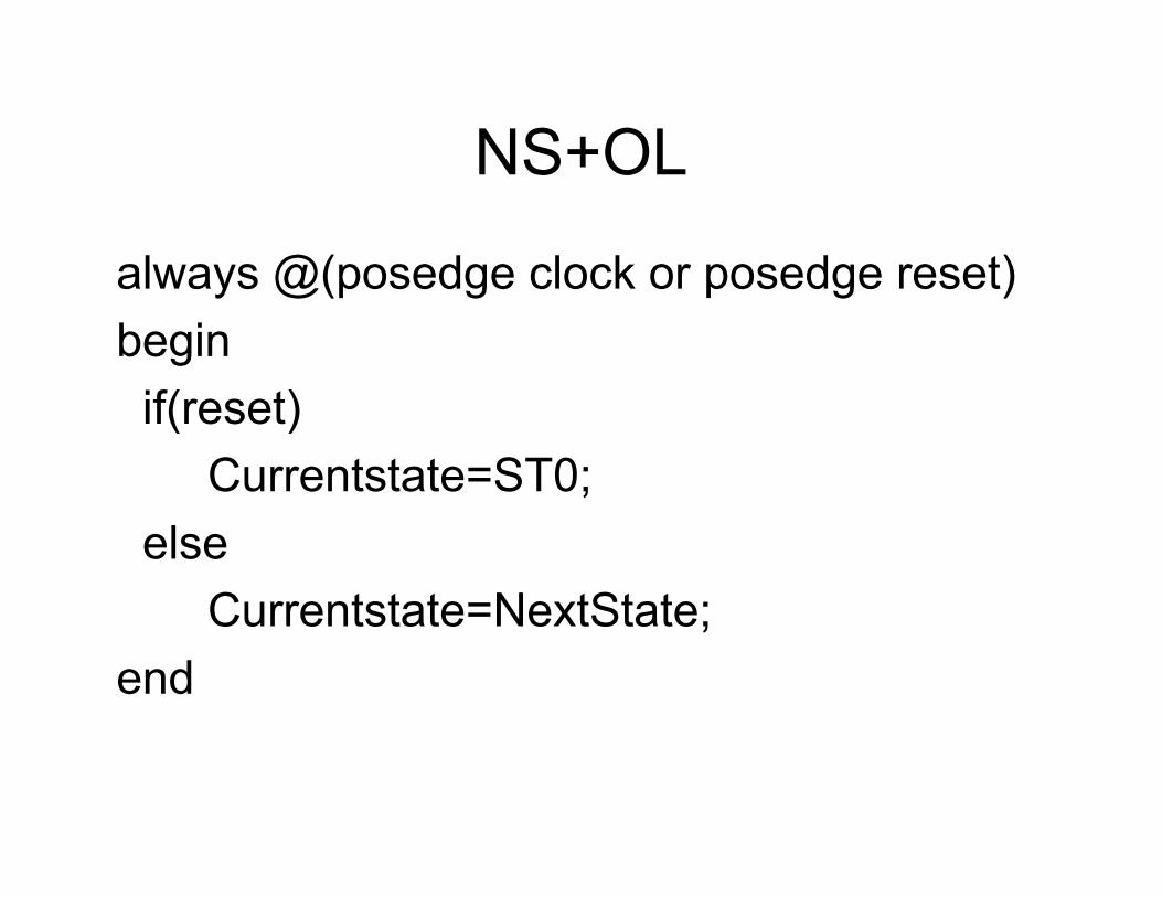
NS+OL
always @(posedge clock or posedge reset)beginif(reset)
Currentstate=ST0;else
Currentstate=NextState;end