MEMORIA DE CÁLCULO Predimensionadode · PDF fileedificios y otras estructuras) y CIRSOC...
24
07 de Mayo de 2014 MEMORIA DE CÁLCULO Predimensionadode Estructura Escuela: Masjoan Ubicación: Córdoba Capital– Pvcia. de Córdoba Memoria descriptiva: El proyecto se compone de una ampliación a construir nueva y la incorporación a la edificación existente de un ascensor planteando las modificaciones necesarias. Para el primer caso la estructura se planteó en función del proyecto arquitectónico propuesto. Se analizaron 2 bloques por separados, uno conformado por la ampliación de aulas y el otro por la galería. En el segundo caso se incorporaron 2 losas y la estructura portante del ascensor. Para ambos casos se realizó el análisis de carga considerando las cargas correspondientes según el caso, haciendo uso del reglamento CIRSOC 101(Reglamento argentino de cargas permanentes y sobrecargas mínimas de diseño para edificios y otras estructuras) y CIRSOC 102 (Reglamento argentino de acción del viento sobre las construcciones). Se cuantificaron igualmente las acciones sísmicas especificadas en la norma CIRSOC 103 (Normas argentinas para construcciones sismorresistentes) propias al caso. Para el dimensionado de la estructura se utilizó la herramienta de cálculo RAM Elements, considerando la normativa vigente, la cual corresponde a los siguientes reglamentos: CIRSOC 103: Normas argentinas para construcciones sismorresistentes. CIRSOC 201: Reglamento argentino de estructuras de hormigón. CIRSOC 301: Reglamento argentino de estructuras de acero para edificios. CIRSOC 303: Reglamento argentino de elementos estructurales de acero de sección abierta conformados en frio. Para definir la fundación se analizó la solución más conveniente según la información relevada a través del estudio de suelo. Se optó por definir una fundación con pilotes a -9.5 m, definiendo 3 tipologías.
Transcript of MEMORIA DE CÁLCULO Predimensionadode · PDF fileedificios y otras estructuras) y CIRSOC...
07 de Mayo de 2014
MEMORIA DE CÁLCULO
Predimensionadode Estructura
Escuela: Masjoan
Ubicación: Córdoba Capital– Pvcia. de Córdoba
Memoria descriptiva:
El proyecto se compone de una ampliación a construir nueva y la incorporación a la edificación
existente de un ascensor planteando las modificaciones necesarias. Para el primer caso la estructura
se planteó en función del proyecto arquitectónico propuesto. Se analizaron 2 bloques por separados,
uno conformado por la ampliación de aulas y el otro por la galería. En el segundo caso se
incorporaron 2 losas y la estructura portante del ascensor. Para ambos casos se realizó el análisis
de carga considerando las cargas correspondientes según el caso, haciendo uso del reglamento
CIRSOC 101(Reglamento argentino de cargas permanentes y sobrecargas mínimas de diseño para
edificios y otras estructuras) y CIRSOC 102 (Reglamento argentino de acción del viento sobre las
construcciones). Se cuantificaron igualmente las acciones sísmicas especificadas en la norma
CIRSOC 103 (Normas argentinas para construcciones sismorresistentes) propias al caso.
Para el dimensionado de la estructura se utilizó la herramienta de cálculo RAM Elements,
considerando la normativa vigente, la cual corresponde a los siguientes reglamentos:
CIRSOC 103: Normas argentinas para construcciones sismorresistentes.
CIRSOC 201: Reglamento argentino de estructuras de hormigón.
CIRSOC 301: Reglamento argentino de estructuras de acero para edificios.
CIRSOC 303: Reglamento argentino de elementos estructurales de acero de sección abierta
conformados en frio.
Para definir la fundación se analizó la solución más conveniente según la información relevada a
través del estudio de suelo. Se optó por definir una fundación con pilotes a -9.5 m, definiendo 3
tipologías.
1-Análisis de carga:
Bloque A:
Bloque B:
2- Losas
Dimensionado Losas:
Losa Lx
[m] Ly
[m] β Dirección de
armado ϒ Espesor [cm]
Espesor adop [cm]
L1 7.20 7.40 1.03 2 D 41.15 18 18
L2 16.20 3.25 4.98 Y 20.00 17 18
L3 7.20 5.15 1.40 2 D 44.18 12 18
L4 5.40 2.70 2.00 Y 20.00 14 18
L5 5.40 7.30 1.35 2 D 43.77 17 18
L6 13.75 2.90 4.74 Y 20.00 15 16
Losa Lx
[m] Ly
[m] β Dirección de
armado ϒ Espesor [cm]
Espesor adop [cm]
LT 2.55 2.70 1.06 2 D 41.40 7 10
Losa Sobrecarga
[tn/m2] Cubierta [tn/m2]
Peso propio
[tn/m2]
L [tn/m2]
D [tn/m2]
1.2D+1.6L 1.4D Qu
[tn/m2]
L1 0.30 0.30 0.43 0.3 0.73 1.36 1.02 1.36
L2 0.30 0.30 0.43 0.3 0.73 1.36 1.02 1.36
L3 0.30 0.30 0.43 0.3 0.73 1.36 1.02 1.36
L4 0.30 0.30 0.43 0.3 0.73 1.36 1.02 1.36
L5 0.30 0.30 0.43 0.3 0.73 1.36 1.02 1.36
L6 0.30 0.30 0.38 0.3 0.68 1.30 0.96 1.30
Losa Sobrecarga
[tn/m2] Agua
[tn/m2]
Peso propio
[tn/m2]
L [tn/m2]
D [tn/m2]
1.2D+1.6L 1.4D Qu
[tn/m2]
LT 0.10 0.40 0.24 0.1 0.64 0.93 0.90 0.93
Condiciones de borde (Método de Marcus)
Losa N° Tipo
de losa
L x L y e Adop Lme/Lma α x α y
Qu M x M y
[m] [m] [cm] [kg/m2] [kgm/m] [kgm/m]
1 L1 7.20 7.40 18 0.97
836 1358.4 0 5887
2 L1 7.20 7.40 18 0.97 691 691 1358.4 4866 4866
3 L2 16.20 3.25 18 0.20
1358.4 0 0
4 L3 7.20 5.15 18 0.72 1090
1358.4 3927 0
5 L4 5.40 2.70 18 0.50 1210
1358.4 1198 0
6 L5 5.40 7.30 18 0.74
562 1358.4 0 2226
7 L5 5.40 7.30 18 0.74
562 1358.4 0 2226
8 L6 16.30 2.95 16 0.18
1300.8 0 0
Armado de Losas : Calculo de momento solicitante y armadura necesaria
Losa N° Lx Ly
Lmen/Lmay e Qu
α x Tramo α y tramo α x Borde α y borde [m] [m] [cm] [kg/m2]
1 7.20 7.40 0.97 18 1358.4 446 318
920
2 7.20 7.40 0.97 18 1358.4 306 367 731 309
3 16.20 3.25 0.20 18 1358.4
4 7.20 5.15 0.72 18 1358.4 562 318 1090
5 5.40 2.70 0.50 18 1358.4
6 5.40 7.30 0.74 18 1358.4 318 562
1090
7 5.40 7.30 0.74 18 1358.4 318 562
1090
8 13.75 2.90 0.21 16 1300.8
LT 2.55 2.70 0.94 10 928
Tramo Borde
Losa N° Mx tramo My tramo Mx borde My borde As x Nec As y Nec As x Nec As y Nec
[kg.m/m] [kg.m/m] [kg.m/m] [kg.m/m] [cm2] [cm2] [cm2] [cm2]
1 3140.71 2239.34 0.00 6478.59 3.82 5.36 11.06 0.00
2 2154.84 2584.39 5147.66 2175.96 4.41 3.68 3.71 8.79
3 551.85 0.00 0.00 0.00 3.60 3.60 0.00 0.00
4 2024.78 1145.70 3927.07 0.00 3.60 3.60 0.00 6.70
5 696.286125 0.00 1237.84 0.00 3.60 3.60 0.00 2.11
6 9048.64 0.00 0.00 0.00 3.60 15.44 0.00 0.00
7 9048.64 0.00 0.00 0.00 3.60 15.44 0.00 0.00
8 471.54 0.00 0.00 0.00 3.20 3.20 0.00 0.00
LT 845.64 0.00 0.00 0.00 2.00 2.98 0.00 0.00
3- Vigas:
Distribución de cargas en losas según dirección:
LOSA L D Lx Ly
Ly/Lx K
marcus
Lx Ly Dx Dy
[kg/m2] [kg/m2] [m] [m] [kg/m2] [kg/m2] [kg/m2] [kg/m2]
1 0.30 0.73 7.20 7.40 1.03 0.738 0.22 0.08 0.54 0.19
2 0.30 0.73 7.20 7.40 1.03 0.529 0.16 0.14 0.39 0.34
3 0.30 0.73 16.20 3.25 0.20 1 0.03 0.30 0.07 0.73
4 0.30 0.73 7.20 5.15 0.72 0.402 0.12 0.18 0.29 0.44
5 0.30 0.73 5.40 2.70 0.50 1 0.03 0.30 0.07 0.73
6 0.30 0.73 5.40 7.30 1.35 0.892 0.27 0.03 0.65 0.08
7 0.30 0.73 5.40 7.30 1.35 0.892 0.27 0.03 0.65 0.08
8 0.30 0.68 13.75 2.90 0.21
0.03 0.30 0.00 0.68
LT 0.10 0.64 2.55 2.70 1.06 0.558 0.06 0.04 0.36 0.28
Distribución de cargas de losas sobre Vigas:
Bloque A:
Vigas en X Losa Losa L viga D viga
Nivel N° l
% L D
N° l
% L D
[m] [kg/m2] [kg/m2] [m] [kg/m2] [kg/m2] [kg/m] [kg/m]
1 1 7.4 0.5 0.079 0.192
0.291 0.711
1 2 7.4 0.4 0.141 0.345
0.418 1.021
1 1 7.4 0.5 0.079 0.192 3 3.25 0.5 0.300 0.732 0.779 1.900
1 2 7.4 0.6 0.141 0.345 4 5.15 0.6 0.179 0.438 1.182 2.883
1 3 3.25 0.5 0.300 0.732
0.488 1.190
1 3 3.25 0.5 0.300 0.732 6 7.3 0.5 0.032 0.079 0.606 1.478
1 3 3.25 0.5 0.300 0.732 7 7.3 0.5 0.032 0.079 0.606 1.478
1 3 3.25 0.5 0.300 0.732 5 2.7 0.6 0.300 0.732 0.974 2.375
1 3 3.25 0.5 0.300 0.732 5 2.7 0.6 0.300 0.732 0.974 2.375
1 4 5.15 0.4 0.179 0.438
0.370 0.902
1 5 2.7 0.4 0.300 0.732
0.324 0.791
1 5 2.7 0.4 0.300 0.732
0.324 0.791
1 6 7.3 0.5 0.032 0.079
0.118 0.289
1 7 7.3 0.5 0.032 0.079
0.118 0.289
2 LT 2.7 0.5 0.044 0.283
0.060 0.382
2 LT 2.7 0.5 0.044 0.283
0.060 0.382
Vigas en Y Losa Losa L viga D viga
Nivel N° l
% L D
N° l
% L D
[m] [kg/m2] [kg/m2] [m] [kg/m2] [kg/m2] [kg/m] [kg/m]
1 6 5.4 0.4 0.268 0.653
0.578 1.410
1 3 16.2 0.5 0.030 0.073
0.243 0.593
1 6 5.4 0.6 0.268 0.653 7 5.4 0.6 0.268 0.653 1.734 4.231
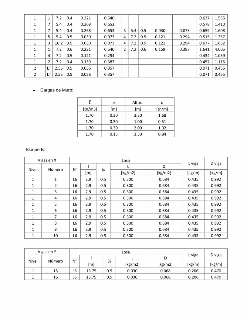
1 1 7.2 0.4 0.221 0.540
0.637 1.555
1 7 5.4 0.4 0.268 0.653
0.578 1.410
1 7 5.4 0.4 0.268 0.653 5 5.4 0.5 0.030 0.073 0.659 1.608
1 5 5.4 0.5 0.030 0.073 4 7.2 0.5 0.121 0.294 0.515 1.257
1 3 16.2 0.5 0.030 0.073 4 7.2 0.5 0.121 0.294 0.677 1.652
1 1 7.2 0.6 0.221 0.540 2 7.2 0.6 0.159 0.387 1.641 4.005
1 4 7.2 0.5 0.121 0.294
0.434 1.059
1 2 7.2 0.4 0.159 0.387
0.457 1.115
2 LT 2.55 0.5 0.056 0.357
0.071 0.455
2 LT 2.55 0.5 0.056 0.357
0.071 0.455
Cargas de Muro:
ϒ e Altura q
[tn/m3] [m] [m] [tn/m]
1.70 0.30 3.30 1.68
1.70 0.30 1.00 0.51
1.70 0.30 2.00 1.02
1.70 0.15 3.30 0.84
Bloque B:
Vigas en X Losa L viga D viga
Nivel Número N° l
% L D
[m] [kg/m2] [kg/m2] [kg/m] [kg/m]
1 1 L6 2.9 0.5 0.300 0.684 0.435 0.992
1 2 L6 2.9 0.5 0.300 0.684 0.435 0.992
1 3 L6 2.9 0.5 0.300 0.684 0.435 0.992
1 4 L6 2.9 0.5 0.300 0.684 0.435 0.992
1 5 L6 2.9 0.5 0.300 0.684 0.435 0.992
1 6 L6 2.9 0.5 0.300 0.684 0.435 0.992
1 7 L6 2.9 0.5 0.300 0.684 0.435 0.992
1 8 L6 2.9 0.5 0.300 0.684 0.435 0.992
1 9 L6 2.9 0.5 0.300 0.684 0.435 0.992
1 10 L6 2.9 0.5 0.300 0.684 0.435 0.992
Vigas en Y Losa L viga D viga
Nivel Número N° l
% L D
[m] [kg/m2] [kg/m2] [kg/m] [kg/m]
1 15 L6 13.75 0.5 0.030 0.068 0.206 0.470
1 16 L6 13.75 0.5 0.030 0.068 0.206 0.470
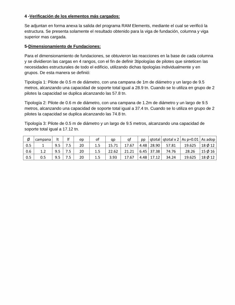
4 -Verificación de los elementos más cargados:
Se adjuntan en forma anexa la salida del programa RAM Elements, mediante el cual se verificó la
estructura. Se presenta solamente el resultado obtenido para la viga de fundación, columna y viga
superior mas cargada.
5-Dimensionamiento de Fundaciones:
Para el dimensionamiento de fundaciones, se obtuvieron las reacciones en la base de cada columna
y se dividieron las cargas en 4 rangos, con el fin de definir 3tipologías de pilotes que sinteticen las
necesidades estructurales de todo el edificio, utilizando dichas tipologías individualmente y en
grupos. De esta manera se definió:
Tipología 1: Pilote de 0.5 m de diámetro, con una campana de 1m de diámetro y un largo de 9.5
metros, alcanzando una capacidad de soporte total igual a 28.9 tn. Cuando se lo utiliza en grupo de 2
pilotes la capacidad se duplica alcanzando las 57.8 tn.
Tipología 2: Pilote de 0.6 m de diámetro, con una campana de 1.2m de diámetro y un largo de 9.5
metros, alcanzando una capacidad de soporte total igual a 37.4 tn. Cuando se lo utiliza en grupo de 2
pilotes la capacidad se duplica alcanzando las 74.8 tn.
Tipología 3: Pilote de 0.5 m de diámetro y un largo de 9.5 metros, alcanzando una capacidad de
soporte total igual a 17.12 tn.
Ø campana lt lf σp σf qp qf pp qtotal qtotal x 2 As p=0.01 As adop
0.5 1 9.5 7.5 20 1.5 15.71 17.67 4.48 28.90 57.81 19.625 18 Ø 12
0.6 1.2 9.5 7.5 20 1.5 22.62 21.21 6.45 37.38 74.76 28.26 15 Ø 16
0.5 0.5 9.5 7.5 20 1.5 3.93 17.67 4.48 17.12 34.24 19.625 18 Ø 12
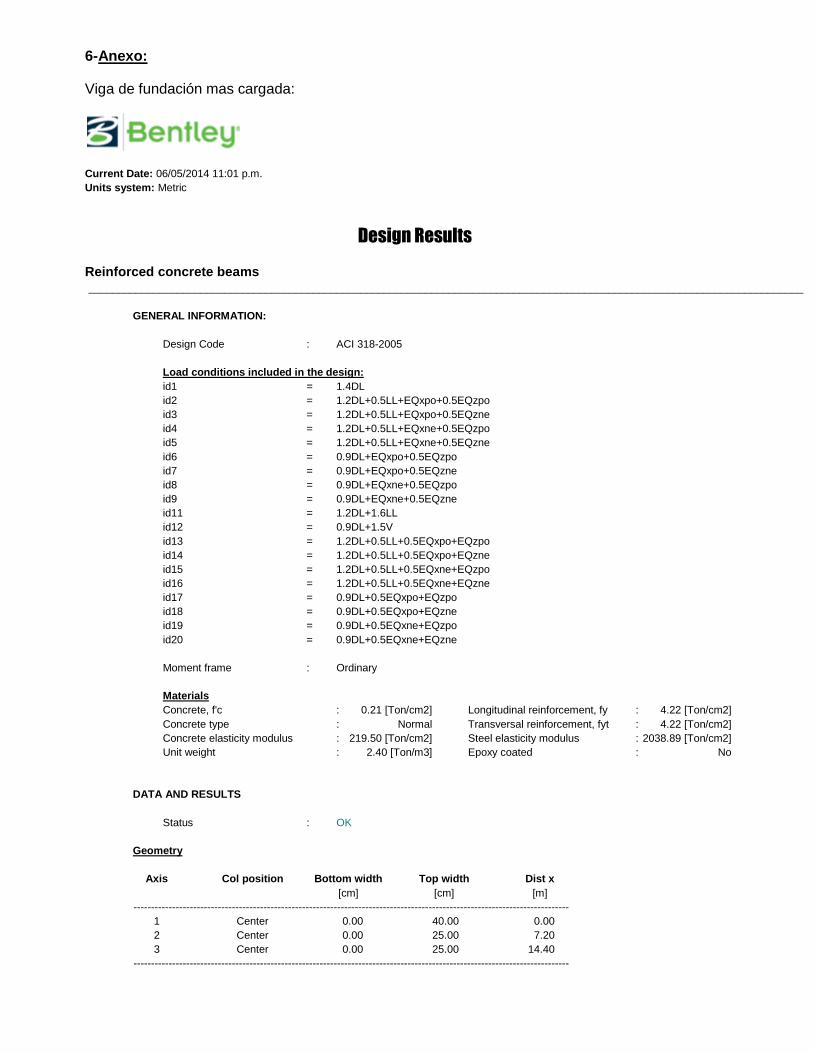
6-Anexo:
Viga de fundación mas cargada:
Current Date: 06/05/2014 11:01 p.m.
Units system: Metric
Design Results
Reinforced concrete beams _________________________________________________________________________________________________________________________
GENERAL INFORMATION:
Design Code : ACI 318-2005
Load conditions included in the design:
id1 = 1.4DL
id2 = 1.2DL+0.5LL+EQxpo+0.5EQzpo
id3 = 1.2DL+0.5LL+EQxpo+0.5EQzne
id4 = 1.2DL+0.5LL+EQxne+0.5EQzpo
id5 = 1.2DL+0.5LL+EQxne+0.5EQzne
id6 = 0.9DL+EQxpo+0.5EQzpo
id7 = 0.9DL+EQxpo+0.5EQzne
id8 = 0.9DL+EQxne+0.5EQzpo
id9 = 0.9DL+EQxne+0.5EQzne
id11 = 1.2DL+1.6LL
id12 = 0.9DL+1.5V
id13 = 1.2DL+0.5LL+0.5EQxpo+EQzpo
id14 = 1.2DL+0.5LL+0.5EQxpo+EQzne
id15 = 1.2DL+0.5LL+0.5EQxne+EQzpo
id16 = 1.2DL+0.5LL+0.5EQxne+EQzne
id17 = 0.9DL+0.5EQxpo+EQzpo
id18 = 0.9DL+0.5EQxpo+EQzne
id19 = 0.9DL+0.5EQxne+EQzpo
id20 = 0.9DL+0.5EQxne+EQzne
Moment frame : Ordinary
Materials
Concrete, f'c : 0.21 [Ton/cm2] Longitudinal reinforcement, fy : 4.22 [Ton/cm2]
Concrete type : Normal Transversal reinforcement, fyt : 4.22 [Ton/cm2]
Concrete elasticity modulus : 219.50 [Ton/cm2] Steel elasticity modulus : 2038.89 [Ton/cm2]
Unit weight : 2.40 [Ton/m3] Epoxy coated : No
DATA AND RESULTS
Status : OK
Geometry
Axis Col position Bottom width Top width Dist x
[cm] [cm] [m]
----------------------------------------------------------------------------------------------------------------------------
1 Center 0.00 40.00 0.00
2 Center 0.00 25.00 7.20
3 Center 0.00 25.00 14.40
----------------------------------------------------------------------------------------------------------------------------
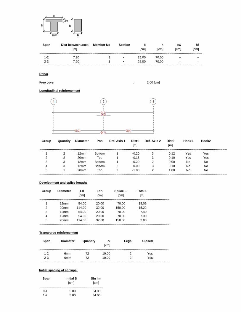
Span Dist between axes Member No Section b h bw hf
[m] [cm] [cm] [cm] [cm]
------------------------------------------------------------------------------------------------------------------------------------------------------------
1-2 7.20 2 • 25.00 70.00 -- --
2-3 7.20 1 • 25.00 70.00 -- --
------------------------------------------------------------------------------------------------------------------------------------------------------------
Rebar
Free cover : 2.00 [cm]
Longitudinal reinforcement
Group Quantity Diameter Pos Ref. Axis 1 Dist1 Ref. Axis 2 Dist2 Hook1 Hook2
[m] [m]
------------------------------------------------------------------------------------------------------------------------------------------------------------------------------------
1 2 12mm Bottom 1 -0.20 3 0.12 Yes Yes
2 2 20mm Top 1 -0.18 3 0.10 Yes Yes
3 3 12mm Bottom 1 -0.20 2 0.00 No No
4 3 12mm Bottom 2 0.00 3 0.10 No No
5 1 20mm Top 2 -1.00 2 1.00 No No
------------------------------------------------------------------------------------------------------------------------------------------------------------------------------------
Development and splice lengths
Group Diameter Ld Ldh Splice L. Total L
[cm] [cm] [cm] [m]
-----------------------------------------------------------------------------------------------------------------------------
1 12mm 54.00 20.00 70.00 15.06
2 20mm 114.00 32.00 150.00 15.22
3 12mm 54.00 20.00 70.00 7.40
4 12mm 54.00 20.00 70.00 7.30
5 20mm 114.00 32.00 150.00 2.00
-----------------------------------------------------------------------------------------------------------------------------
Transverse reinforcement
Span Diameter Quantity c/ Legs Closed
[cm]
----------------------------------------------------------------------------------------------------------------------------
1-2 6mm 72 10.00 2 Yes
2-3 6mm 72 10.00 2 Yes
----------------------------------------------------------------------------------------------------------------------------
Initial spacing of stirrups:
Span Initial S Sin lim
[cm] [cm]
-------------------------------------------------------------
0-1 5.00 34.00
1-2 5.00 34.00
-------------------------------------------------------------
FLEXURE
Span: 1-2 Member No: 2
Percentage of moment redistribution Support A = 0.00% Support B = 0.00%
Code specified max Rho: maxtop= 1.55% maxbot= 1.55%
Limit spacing between bars for cracking control: sblim = 30.48 [cm]
Positive bending moments
Station d[cm] Mu[Ton*m] *Mn[Ton*m] Asreq[cm2] Asprov[cm2] (%) sb[cm] Mu/( *Mn)
No. Dist
-------------------------------------------------------------------------------------------------------------------------------------------------------------------------------------------
1 0% 66.80 2.42 8.78 1.28 3.55 0.21 3.15 0.69
2 10% 66.80 5.40 13.76 2.88 5.65 0.34 3.15 0.39
3 20% 66.80 8.14 13.76 4.38 5.65 0.34 3.15 0.59
4 30% 66.80 9.58 13.76 5.18 5.65 0.34 3.15 0.70
5 40% 66.80 9.72 13.76 5.25 5.65 0.34 3.15 0.71
6 50% 66.80 8.54 13.76 4.60 5.65 0.34 3.15 0.62
7 60% 66.80 6.15 13.76 3.29 5.65 0.34 3.15 0.45
8 70% 66.80 2.56 13.76 1.35 5.65 0.34 3.15 0.19
9 80% 66.80 0.00 13.76 0.00 5.65 0.34 3.15 0.19
10 90% 66.80 0.00 13.76 0.00 5.65 0.34 3.15 0.53
11 100% 66.80 0.00 5.64 0.00 2.26 0.14 3.15 0.78
-------------------------------------------------------------------------------------------------------------------------------------------------------------------------------------------
C 100% 66.80 0.00 5.64 0.00 2.26 0.14 3.15 0.78
-------------------------------------------------------------------------------------------------------------------------------------------------------------------------------------------
Negative bending moments
Station d[cm] Mu[Ton*m] *Mn[Ton*m] Asreq[cm2] Asprov[cm2] (%) sb[cm] Mu/( *Mn)
No. Dist
-------------------------------------------------------------------------------------------------------------------------------------------------------------------------------------------
1 0% 66.40 -9.05 -13.03 4.91 5.37 0.32 15.40 0.69
2 10% 66.40 -3.67 -15.13 1.96 6.28 0.38 15.40 0.39
3 20% 66.40 -0.36 -15.13 0.19 6.28 0.38 15.40 0.59
4 30% 66.40 0.00 -15.13 0.00 6.28 0.38 15.40 0.70
5 40% 66.40 0.00 -15.13 0.00 6.28 0.38 15.40 0.71
6 50% 66.40 0.00 -15.13 0.00 6.28 0.38 15.40 0.62
7 60% 66.40 0.00 -15.13 0.00 6.28 0.38 15.40 0.45
8 70% 66.40 0.00 -15.13 0.00 6.28 0.38 15.40 0.19
9 80% 66.40 -2.82 -15.13 1.50 6.28 0.38 15.40 0.19
10 90% 66.40 -9.22 -17.41 5.01 7.28 0.44 6.70 0.53
11 100% 66.40 -17.35 -22.16 7.26 9.42 0.57 6.70 0.78
-------------------------------------------------------------------------------------------------------------------------------------------------------------------------------------------
C 100% 66.40 -17.35 -22.16 7.26 9.42 0.57 6.70 0.78
-------------------------------------------------------------------------------------------------------------------------------------------------------------------------------------------
Span: 2-3 Member No: 1
Percentage of moment redistribution Support A = 0.00% Support B = 0.00%
Code specified max Rho: maxtop= 1.55% maxbot= 1.55%
Limit spacing between bars for cracking control: sblim = 30.48 [cm]
Positive bending moments
Station d[cm] Mu[Ton*m] *Mn[Ton*m] Asreq[cm2] Asprov[cm2] (%) sb[cm] Mu/( *Mn)
No. Dist
-------------------------------------------------------------------------------------------------------------------------------------------------------------------------------------------
1 0% 66.80 0.00 5.64 0.00 2.26 0.14 3.15 0.77
2 10% 66.80 0.00 13.76 0.00 5.65 0.34 3.15 0.50
3 20% 66.80 0.00 13.76 0.00 5.65 0.34 3.15 0.13
4 30% 66.80 3.25 13.76 1.73 5.65 0.34 3.15 0.24
5 40% 66.80 6.97 13.76 3.74 5.65 0.34 3.15 0.51
6 50% 66.80 9.16 13.76 4.94 5.65 0.34 3.15 0.67
7 60% 66.80 9.82 13.76 5.31 5.65 0.34 3.15 0.71
8 70% 66.80 9.32 13.76 5.04 5.65 0.34 3.15 0.68
9 80% 66.80 7.63 13.76 4.10 5.65 0.34 3.15 0.55
10 90% 66.80 4.64 13.76 2.47 5.65 0.34 3.15 0.34
11 100% 66.80 1.03 6.55 0.54 2.63 0.16 3.15 0.45
-------------------------------------------------------------------------------------------------------------------------------------------------------------------------------------------
C 0% 66.80 0.00 5.64 0.00 2.26 0.14 3.15 0.77
-------------------------------------------------------------------------------------------------------------------------------------------------------------------------------------------
Negative bending moments
Station d[cm] Mu[Ton*m] *Mn[Ton*m] Asreq[cm2] Asprov[cm2] (%) sb[cm] Mu/( *Mn)
No. Dist
-------------------------------------------------------------------------------------------------------------------------------------------------------------------------------------------
1 0% 66.40 -17.02 -22.16 7.11 9.42 0.57 6.70 0.77
2 10% 66.40 -8.74 -17.41 4.74 7.28 0.44 6.70 0.50
3 20% 66.40 -1.98 -15.13 1.05 6.28 0.38 15.40 0.13
4 30% 66.40 0.00 -15.13 0.00 6.28 0.38 15.40 0.24
5 40% 66.40 0.00 -15.13 0.00 6.28 0.38 15.40 0.51
6 50% 66.40 0.00 -15.13 0.00 6.28 0.38 15.40 0.67
7 60% 66.40 0.00 -15.13 0.00 6.28 0.38 15.40 0.71
8 70% 66.40 0.00 -15.13 0.00 6.28 0.38 15.40 0.68
9 80% 66.40 0.00 -15.13 0.00 6.28 0.38 15.40 0.55
10 90% 66.40 -0.73 -15.13 0.39 6.28 0.38 15.40 0.34
11 100% 66.40 -5.28 -11.69 2.84 4.80 0.29 15.40 0.45
-------------------------------------------------------------------------------------------------------------------------------------------------------------------------------------------
C 0% 66.40 -17.02 -22.16 7.11 9.42 0.57 6.70 0.77
-------------------------------------------------------------------------------------------------------------------------------------------------------------------------------------------
SHEAR AND TORSION
Span: 1-2 Member No: 2
Station Stirrups Spcprov Spclim Tu *Tn Al Vu Vs Vc *Vn Vu/( *Vn)
No. Dist Diam VCT [cm] [cm] [Ton*m] [Ton*m] [cm2] [Ton] [Ton] [Ton] [Ton]
-----------------------------------------------------------------------------------------------------------------------------------------------------------------------------------------------------
1 0% 6mm V 10.00 27.17 0.00 2.03 0.00 6.88 15.95 12.86 21.61 0.32
2 10% 6mm V 10.00 27.17 0.00 2.03 0.00 6.74 15.95 12.86 21.61 0.31
3 20% 6mm V 10.00 27.17 0.00 2.03 0.00 4.93 15.95 12.86 21.61 0.23
4 30% 6mm 10.00 27.17 0.00 2.03 0.00 3.12 15.95 12.86 21.61 0.14
5 40% 6mm 10.00 27.17 0.00 2.03 0.00 1.30 15.95 12.86 21.61 0.06
6 50% 6mm 10.00 27.17 0.00 2.03 0.00 2.54 15.95 12.86 21.61 0.12
7 60% 6mm 10.00 27.17 0.00 2.03 0.00 4.35 15.95 12.86 21.61 0.20
8 70% 6mm V 10.00 27.17 0.00 2.03 0.00 6.17 15.95 12.86 21.61 0.29
9 80% 6mm V 10.00 27.17 0.00 2.03 0.00 8.16 15.85 12.78 21.48 0.38
10 90% 6mm V 10.00 27.17 0.00 1.91 0.00 10.28 15.85 12.78 21.48 0.48
11 100% 6mm V 10.00 27.17 0.00 1.89 0.00 10.43 15.85 12.78 21.48 0.49
-----------------------------------------------------------------------------------------------------------------------------------------------------------------------------------------------------
C 92% 6mm V 10.00 27.17 0.00 1.89 0.00 10.43 15.85 12.78 21.48 0.49
-----------------------------------------------------------------------------------------------------------------------------------------------------------------------------------------------------
Span: 2-3 Member No: 1
Station Stirrups Spcprov Spclim Tu *Tn Al Vu Vs Vc *Vn Vu/( *Vn)
No. Dist Diam VCT [cm] [cm] [Ton*m] [Ton*m] [cm2] [Ton] [Ton] [Ton] [Ton]
-----------------------------------------------------------------------------------------------------------------------------------------------------------------------------------------------------
1 0% 6mm V 10.00 27.17 0.01 1.86 0.00 10.60 15.85 12.78 21.48 0.49
2 10% 6mm V 10.00 27.17 0.01 1.88 0.00 10.45 15.85 12.78 21.48 0.49
3 20% 6mm V 10.00 27.17 0.01 2.03 0.00 8.33 15.85 12.78 21.48 0.39
4 30% 6mm V 10.00 27.17 0.01 2.03 0.00 6.21 15.95 12.86 21.61 0.29
5 40% 6mm 10.00 27.17 0.01 2.03 0.00 4.10 15.95 12.86 21.61 0.19
6 50% 6mm 10.00 27.17 0.01 2.03 0.00 2.19 15.95 12.86 21.61 0.10
7 60% 6mm 10.00 27.17 0.01 2.03 0.00 0.66 15.95 12.86 21.61 0.03
8 70% 6mm 10.00 27.17 0.01 2.03 0.00 2.47 15.95 12.86 21.61 0.11
9 80% 6mm 10.00 27.17 0.01 2.03 0.00 4.37 15.95 12.86 21.61 0.20
10 90% 6mm V 10.00 27.17 0.01 2.03 0.00 6.49 15.95 12.86 21.61 0.30
11 100% 6mm V 10.00 27.17 0.01 2.03 0.00 6.64 15.95 12.86 21.61 0.31
-----------------------------------------------------------------------------------------------------------------------------------------------------------------------------------------------------
C 0% 6mm V 10.00 27.17 0.01 1.86 0.00 10.60 15.85 12.78 21.48 0.49
-----------------------------------------------------------------------------------------------------------------------------------------------------------------------------------------------------
Notes
* Only the design bending forces (Mu), shear forces (Vu) and torsion moments (Tu) are considered in the design.
* Values shown in red are not in compliance with a provision of the code
* The positive and negative flexural reinforcement includes the longitudinal reinforcement required to resist torsion. Refer to the note below
on the VCT column to determine when torsion and compression bars are provided. The longitudinal reinforcement area considers the
minimum area required by Code (10.5).
* When the moments diagram increases in the same direction of the development length of the bars, the bars will not contribute to the
member strength for a Code specified distance equal to max(12*db,d).
* If the section at which member flexural strength is being calculated is within the development length of a group of bars, the bars will
contribute to the bending capacity an amount proportional to their actual length / their full development length.
* The transverse reinforcement is ordered from left to right.
* The program does not consider ACI318-05 section 12.11.3 whereby the bar diameter is limited according to the location of the bar cut-off.
* Asprov is the provided reinforcement, considering the reduction due to the development length as described previously.
* "C" shows the span critical station.
* Ld,Ldh = Development length of each bar. If the bar ends with a hook, it considers the Ldh length.
* Splice lengths shown are not reduced by the factor Asreq/Asprov.
* sb = Free distance between top or bottom bars corresponding to the layer closest to the extreme face of the beam (layer1). It is not
calculated when there is only one bar.
* Stirrups VCT = Flag that determines if stirrups are required to resist shear forces (V), torsion (T) or to confine the the longitudinal
compression bars from buckling (C).
* Closed = Flag that indicates if the stirrups are closed (yes) or open (no).
* Mu/( *Mn) = Critical strength ratio for the station. If the value is in red, it is larger than 1.0
* Al = Total additional longitudinal reinforcement required by torsion.
* Spa = stirrup spacing provided by the user.
* Spa lim = spacing limits due to geometry. (11.5.5.1, 11.5.5.3, 21.3.3.2, 21.12.4.2)
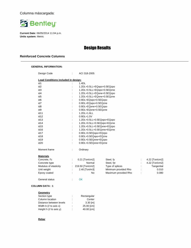
Columna máscargada:
Current Date: 06/05/2014 11:04 p.m.
Units system: Metric
Design Results
Reinforced Concrete Columns _________________________________________________________________________________________________________________________
GENERAL INFORMATION:
Design Code : ACI 318-2005
Load Conditions included in design:
id1 : 1.4DL
id2 : 1.2DL+0.5LL+EQxpo+0.5EQzpo
id3 : 1.2DL+0.5LL+EQxpo+0.5EQzne
id4 : 1.2DL+0.5LL+EQxne+0.5EQzpo
id5 : 1.2DL+0.5LL+EQxne+0.5EQzne
id6 : 0.9DL+EQxpo+0.5EQzpo
id7 : 0.9DL+EQxpo+0.5EQzne
id8 : 0.9DL+EQxne+0.5EQzpo
id9 : 0.9DL+EQxne+0.5EQzne
id11 : 1.2DL+1.6LL
id12 : 0.9DL+1.5V
id13 : 1.2DL+0.5LL+0.5EQxpo+EQzpo
id14 : 1.2DL+0.5LL+0.5EQxpo+EQzne
id15 : 1.2DL+0.5LL+0.5EQxne+EQzpo
id16 : 1.2DL+0.5LL+0.5EQxne+EQzne
id17 : 0.9DL+0.5EQxpo+EQzpo
id18 : 0.9DL+0.5EQxpo+EQzne
id19 : 0.9DL+0.5EQxne+EQzpo
id20 : 0.9DL+0.5EQxne+EQzne
Moment frame : Ordinary
Materials
Concrete, f'c : 0.21 [Ton/cm2] Steel, fy : 4.22 [Ton/cm2]
Concrete type : Normal Steel, fyt : 4.22 [Ton/cm2]
Modulus of elasticity : 219.50 [Ton/cm2] Type of splices : Tangential
Unit weight : 2.40 [Ton/m3] Minimum provided Rho : 0.010
Epoxy coated : No Maximum provided Rho : 0.080
General status : OK
COLUMN DATA : 1
Geometry
Section type : Rectangular
Column location : Center
Distance between levels : 3.30 [m]
Width b (// to axis x) : 25.00 [cm]
Height h (// to axis y) : 40.00 [cm]
Rebar
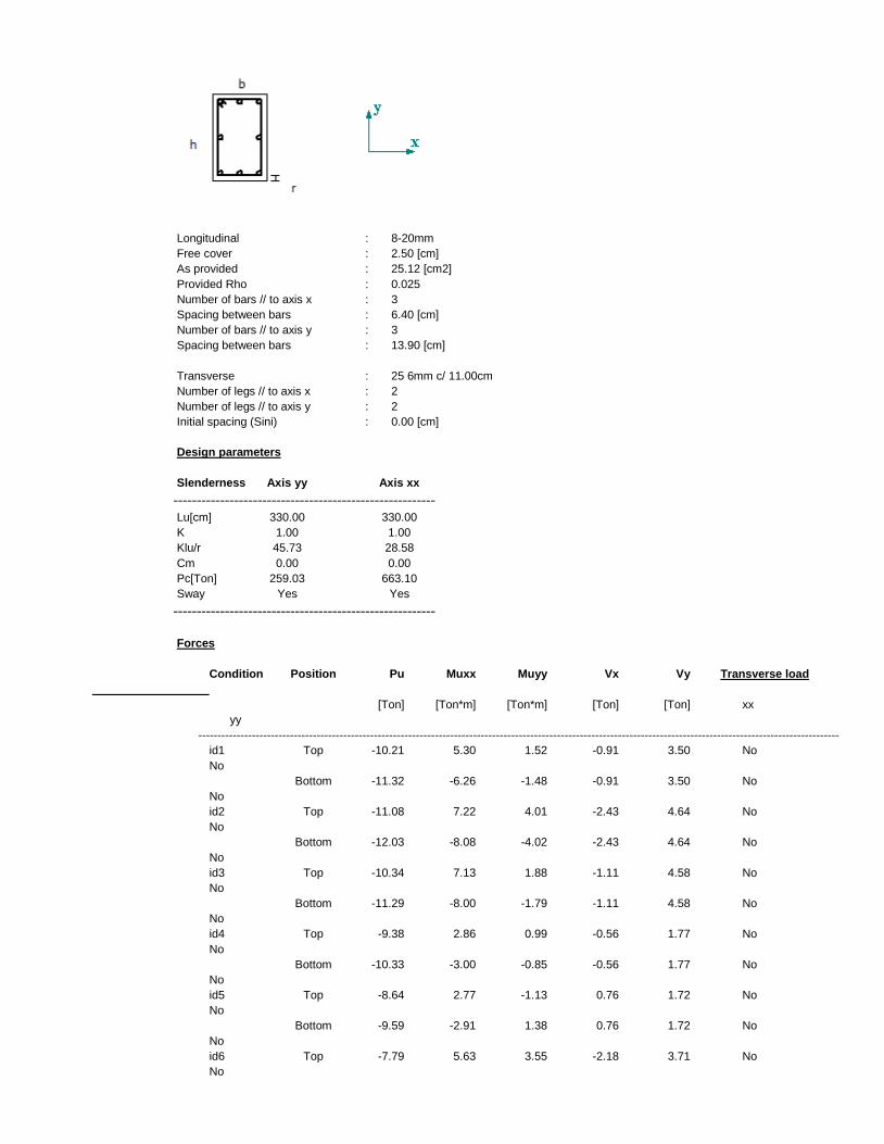
Longitudinal : 8-20mm
Free cover : 2.50 [cm]
As provided : 25.12 [cm2]
Provided Rho : 0.025
Number of bars // to axis x : 3
Spacing between bars : 6.40 [cm]
Number of bars // to axis y : 3
Spacing between bars : 13.90 [cm]
Transverse : 25 6mm c/ 11.00cm
Number of legs // to axis x : 2
Number of legs // to axis y : 2
Initial spacing (Sini) : 0.00 [cm]
Design parameters
Slenderness Axis yy Axis xx
--------------------------------------------------------
Lu[cm] 330.00 330.00
K 1.00 1.00
Klu/r 45.73 28.58
Cm 0.00 0.00
Pc[Ton] 259.03 663.10
Sway Yes Yes
--------------------------------------------------------
Forces
Condition Position Pu Muxx Muyy Vx Vy Transverse load
[Ton] [Ton*m] [Ton*m] [Ton] [Ton] xx
yy
------------------------------------------------------------------------------------------------------------------------------------------------------------------------
id1 Top -10.21 5.30 1.52 -0.91 3.50 No
No
Bottom -11.32 -6.26 -1.48 -0.91 3.50 No
No
id2 Top -11.08 7.22 4.01 -2.43 4.64 No
No
Bottom -12.03 -8.08 -4.02 -2.43 4.64 No
No
id3 Top -10.34 7.13 1.88 -1.11 4.58 No
No
Bottom -11.29 -8.00 -1.79 -1.11 4.58 No
No
id4 Top -9.38 2.86 0.99 -0.56 1.77 No
No
Bottom -10.33 -3.00 -0.85 -0.56 1.77 No
No
id5 Top -8.64 2.77 -1.13 0.76 1.72 No
No
Bottom -9.59 -2.91 1.38 0.76 1.72 No
No
id6 Top -7.79 5.63 3.55 -2.18 3.71 No
No
Bottom -8.50 -6.61 -3.65 -2.18 3.71 No
No
id7 Top -7.04 5.54 1.42 -0.86 3.66 No
No
Bottom -7.75 -6.53 -1.42 -0.86 3.66 No
No
id8 Top -6.08 1.27 0.53 -0.31 0.85 No
No
Bottom -6.80 -1.52 -0.48 -0.31 0.85 No
No
id9 Top -5.34 1.18 -1.59 1.01 0.79 No
No
Bottom -6.05 -1.44 1.75 1.01 0.79 No
No
id11 Top -12.30 5.98 1.73 -0.96 3.56 No
No
Bottom -13.25 -5.78 -1.43 -0.96 3.56 No
No
id12 Top -6.56 3.41 0.98 -0.58 2.25 No
No
Bottom -7.28 -4.03 -0.95 -0.58 2.25 No
No
id13 Top -11.03 6.17 4.31 -2.62 3.95 No
No
Bottom -11.98 -6.85 -4.34 -2.62 3.95 No
No
id14 Top -9.54 5.99 0.07 0.02 3.84 No
No
Bottom -10.49 -6.68 0.12 0.02 3.84 No
No
id15 Top -10.18 3.99 2.81 -1.69 2.52 No
No
Bottom -11.13 -4.31 -2.76 -1.69 2.52 No
No
id16 Top -8.69 3.81 -1.44 0.95 2.41 No
No
Bottom -9.64 -4.14 1.71 0.95 2.41 No
No
id17 Top -7.73 4.59 3.85 -2.37 3.02 No
No
Bottom -8.45 -5.38 -3.97 -2.37 3.02 No
No
id18 Top -6.24 4.41 -0.39 0.27 2.91 No
No
Bottom -6.96 -5.21 0.49 0.27 2.91 No
No
id19 Top -6.88 2.41 2.35 -1.44 1.59 No
No
Bottom -7.60 -2.84 -2.39 -1.44 1.59 No
No
id20 Top -5.39 2.23 -1.90 1.20 1.48 No
No
Bottom -6.11 -2.67 2.08 1.20 1.48 No
No
------------------------------------------------------------------------------------------------------------------------------------------------------------------------
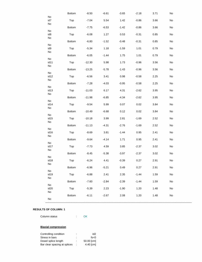
RESULTS OF COLUMN: 1
Column status : OK
Biaxial compression
Controlling condition : id2
Stress in bars : fs<0
Dowel splice length : 50.00 [cm]
Bar clear spacing at splices : 4.40 [cm]
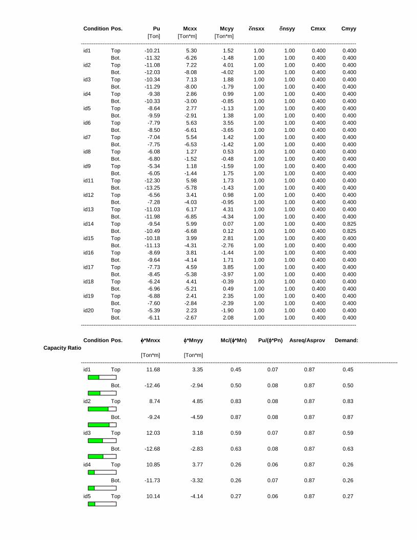
Condition Pos. Pu Mcxx Mcyy nsxx nsyy Cmxx Cmyy
[Ton] [Ton*m] [Ton*m]
---------------------------------------------------------------------------------------------------------------------------------------------------------
id1 Top -10.21 5.30 1.52 1.00 1.00 0.400 0.400
Bot. -11.32 -6.26 -1.48 1.00 1.00 0.400 0.400
id2 Top -11.08 7.22 4.01 1.00 1.00 0.400 0.400
Bot. -12.03 -8.08 -4.02 1.00 1.00 0.400 0.400
id3 Top -10.34 7.13 1.88 1.00 1.00 0.400 0.400
Bot. -11.29 -8.00 -1.79 1.00 1.00 0.400 0.400
id4 Top -9.38 2.86 0.99 1.00 1.00 0.400 0.400
Bot. -10.33 -3.00 -0.85 1.00 1.00 0.400 0.400
id5 Top -8.64 2.77 -1.13 1.00 1.00 0.400 0.400
Bot. -9.59 -2.91 1.38 1.00 1.00 0.400 0.400
id6 Top -7.79 5.63 3.55 1.00 1.00 0.400 0.400
Bot. -8.50 -6.61 -3.65 1.00 1.00 0.400 0.400
id7 Top -7.04 5.54 1.42 1.00 1.00 0.400 0.400
Bot. -7.75 -6.53 -1.42 1.00 1.00 0.400 0.400
id8 Top -6.08 1.27 0.53 1.00 1.00 0.400 0.400
Bot. -6.80 -1.52 -0.48 1.00 1.00 0.400 0.400
id9 Top -5.34 1.18 -1.59 1.00 1.00 0.400 0.400
Bot. -6.05 -1.44 1.75 1.00 1.00 0.400 0.400
id11 Top -12.30 5.98 1.73 1.00 1.00 0.400 0.400
Bot. -13.25 -5.78 -1.43 1.00 1.00 0.400 0.400
id12 Top -6.56 3.41 0.98 1.00 1.00 0.400 0.400
Bot. -7.28 -4.03 -0.95 1.00 1.00 0.400 0.400
id13 Top -11.03 6.17 4.31 1.00 1.00 0.400 0.400
Bot. -11.98 -6.85 -4.34 1.00 1.00 0.400 0.400
id14 Top -9.54 5.99 0.07 1.00 1.00 0.400 0.825
Bot. -10.49 -6.68 0.12 1.00 1.00 0.400 0.825
id15 Top -10.18 3.99 2.81 1.00 1.00 0.400 0.400
Bot. -11.13 -4.31 -2.76 1.00 1.00 0.400 0.400
id16 Top -8.69 3.81 -1.44 1.00 1.00 0.400 0.400
Bot. -9.64 -4.14 1.71 1.00 1.00 0.400 0.400
id17 Top -7.73 4.59 3.85 1.00 1.00 0.400 0.400
Bot. -8.45 -5.38 -3.97 1.00 1.00 0.400 0.400
id18 Top -6.24 4.41 -0.39 1.00 1.00 0.400 0.400
Bot. -6.96 -5.21 0.49 1.00 1.00 0.400 0.400
id19 Top -6.88 2.41 2.35 1.00 1.00 0.400 0.400
Bot. -7.60 -2.84 -2.39 1.00 1.00 0.400 0.400
id20 Top -5.39 2.23 -1.90 1.00 1.00 0.400 0.400
Bot. -6.11 -2.67 2.08 1.00 1.00 0.400 0.400
---------------------------------------------------------------------------------------------------------------------------------------------------------
Condition Pos. *Mnxx *Mnyy Mc/( *Mn) Pu/( *Pn) Asreq/Asprov Demand:
Capacity Ratio
[Ton*m] [Ton*m]
--------------------------------------------------------------------------------------------------------------------------------------------------------------------------------
id1 Top 11.68 3.35 0.45 0.07 0.87 0.45
Bot. -12.46 -2.94 0.50 0.08 0.87 0.50
id2 Top 8.74 4.85 0.83 0.08 0.87 0.83
Bot. -9.24 -4.59 0.87 0.08 0.87 0.87
id3 Top 12.03 3.18 0.59 0.07 0.87 0.59
Bot. -12.68 -2.83 0.63 0.08 0.87 0.63
id4 Top 10.85 3.77 0.26 0.06 0.87 0.26
Bot. -11.73 -3.32 0.26 0.07 0.87 0.26
id5 Top 10.14 -4.14 0.27 0.06 0.87 0.27
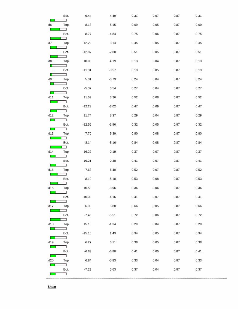
Bot. -9.44 4.49 0.31 0.07 0.87 0.31
id6 Top 8.18 5.15 0.69 0.05 0.87 0.69
Bot. -8.77 -4.84 0.75 0.06 0.87 0.75
id7 Top 12.22 3.14 0.45 0.05 0.87 0.45
Bot. -12.87 -2.80 0.51 0.05 0.87 0.51
id8 Top 10.05 4.19 0.13 0.04 0.87 0.13
Bot. -11.31 -3.57 0.13 0.05 0.87 0.13
id9 Top 5.01 -6.73 0.24 0.04 0.87 0.24
Bot. -5.37 6.54 0.27 0.04 0.87 0.27
id11 Top 11.59 3.36 0.52 0.08 0.87 0.52
Bot. -12.23 -3.02 0.47 0.09 0.87 0.47
id12 Top 11.74 3.37 0.29 0.04 0.87 0.29
Bot. -12.56 -2.96 0.32 0.05 0.87 0.32
id13 Top 7.70 5.39 0.80 0.08 0.87 0.80
Bot. -8.14 -5.16 0.84 0.08 0.87 0.84
id14 Top 16.22 0.19 0.37 0.07 0.87 0.37
Bot. -16.21 0.30 0.41 0.07 0.87 0.41
id15 Top 7.68 5.40 0.52 0.07 0.87 0.52
Bot. -8.10 -5.18 0.53 0.08 0.87 0.53
id16 Top 10.50 -3.96 0.36 0.06 0.87 0.36
Bot. -10.09 4.16 0.41 0.07 0.87 0.41
id17 Top 6.90 5.80 0.66 0.05 0.87 0.66
Bot. -7.46 -5.51 0.72 0.06 0.87 0.72
id18 Top 15.13 -1.34 0.29 0.04 0.87 0.29
Bot. -15.15 1.43 0.34 0.05 0.87 0.34
id19 Top 6.27 6.11 0.38 0.05 0.87 0.38
Bot. -6.89 -5.80 0.41 0.05 0.87 0.41
id20 Top 6.84 -5.83 0.33 0.04 0.87 0.33
Bot. -7.23 5.63 0.37 0.04 0.87 0.37
--------------------------------------------------------------------------------------------------------------------------------------------------------------------------------
Shear
S provided : 11.00 [cm] S required : 11.25 [cm]
Sini provided : 0.00 [cm] Sini required : 5.63 [cm]
Dir Condition Pos. Vu Vc Vs *Vn Vu/( *Vn)
Gob. [Ton] [Ton] [Ton] [Ton]
--------------------------------------------------------------------------------------------------------------------------------------------------
2 id2 Top 4.64 7.79 8.14 11.95 0.39
Bot. 4.64 7.84 8.14 11.98 0.39
3 id13 Top 2.62 7.48 4.88 9.27 0.28
Bot. 2.62 7.52 4.88 9.30 0.28
--------------------------------------------------------------------------------------------------------------------------------------------------
Notes
* Torsion is not considered for design.
* Only columns with rectangular or circular sections are designed.
* Each column is verified considering only the forces at the ends of the member.
* The transverse reinforcement is ordered from bottom to top of the column.
* Lu = Unsupported length.
* K = Effective length factor.
* Cm = A factor relating actual moment diagram to an equivalent uniform moment diagram.
* Sway = True if column is considered unbraced in its local axis.
* Mc = Factored moment to be used for design. Considers the slenderness effects of the column. Mc = Mu* ns.
* n2 = Amplification factor to account for small P-delta effects (P- ).
* Mn = Nominal moment strength.
* Mc/( *Mn) = Strength ratio. The bar graphs indicate the relative ratio of Mc/( *Mn) for each load condition. If a bar is shown in red the ratio
is greater than one.
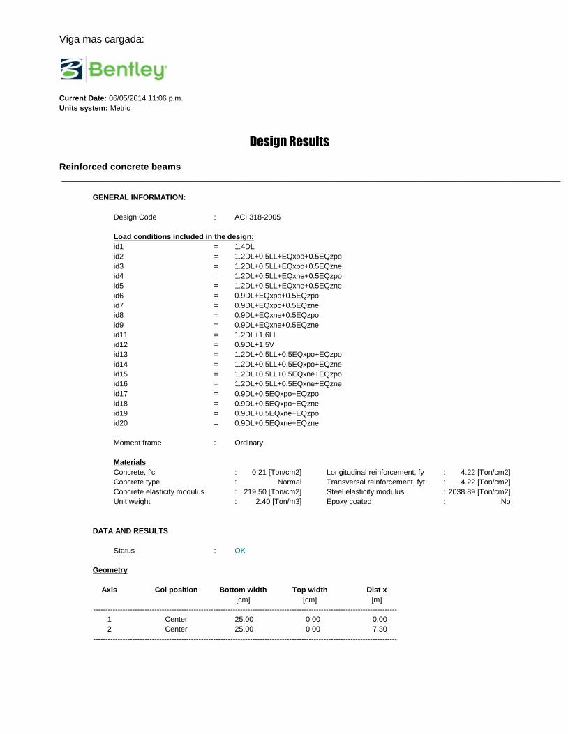
Viga mas cargada:
Current Date: 06/05/2014 11:06 p.m.
Units system: Metric
Design Results
Reinforced concrete beams _________________________________________________________________________________________________________________________
GENERAL INFORMATION:
Design Code : ACI 318-2005
Load conditions included in the design:
id1 = 1.4DL
id2 = 1.2DL+0.5LL+EQxpo+0.5EQzpo
id3 = 1.2DL+0.5LL+EQxpo+0.5EQzne
id4 = 1.2DL+0.5LL+EQxne+0.5EQzpo
id5 = 1.2DL+0.5LL+EQxne+0.5EQzne
id6 = 0.9DL+EQxpo+0.5EQzpo
id7 = 0.9DL+EQxpo+0.5EQzne
id8 = 0.9DL+EQxne+0.5EQzpo
id9 = 0.9DL+EQxne+0.5EQzne
id11 = 1.2DL+1.6LL
id12 = 0.9DL+1.5V
id13 = 1.2DL+0.5LL+0.5EQxpo+EQzpo
id14 = 1.2DL+0.5LL+0.5EQxpo+EQzne
id15 = 1.2DL+0.5LL+0.5EQxne+EQzpo
id16 = 1.2DL+0.5LL+0.5EQxne+EQzne
id17 = 0.9DL+0.5EQxpo+EQzpo
id18 = 0.9DL+0.5EQxpo+EQzne
id19 = 0.9DL+0.5EQxne+EQzpo
id20 = 0.9DL+0.5EQxne+EQzne
Moment frame : Ordinary
Materials
Concrete, f'c : 0.21 [Ton/cm2] Longitudinal reinforcement, fy : 4.22 [Ton/cm2]
Concrete type : Normal Transversal reinforcement, fyt : 4.22 [Ton/cm2]
Concrete elasticity modulus : 219.50 [Ton/cm2] Steel elasticity modulus : 2038.89 [Ton/cm2]
Unit weight : 2.40 [Ton/m3] Epoxy coated : No
DATA AND RESULTS
Status : OK
Geometry
Axis Col position Bottom width Top width Dist x
[cm] [cm] [m]
----------------------------------------------------------------------------------------------------------------------------
1 Center 25.00 0.00 0.00
2 Center 25.00 0.00 7.30
----------------------------------------------------------------------------------------------------------------------------
Span Dist between axes Member No Section b h bw hf
[m] [cm] [cm] [cm] [cm]
------------------------------------------------------------------------------------------------------------------------------------------------------------
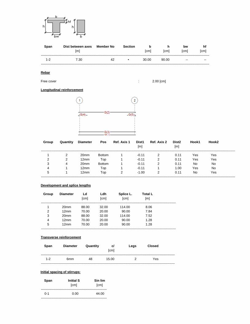
1-2 7.30 42 • 30.00 90.00 -- --
------------------------------------------------------------------------------------------------------------------------------------------------------------
Rebar
Free cover : 2.00 [cm]
Longitudinal reinforcement
Group Quantity Diameter Pos Ref. Axis 1 Dist1 Ref. Axis 2 Dist2 Hook1 Hook2
[m] [m]
------------------------------------------------------------------------------------------------------------------------------------------------------------------------------------
1 2 20mm Bottom 1 -0.11 2 0.11 Yes Yes
2 2 12mm Top 1 -0.11 2 0.11 Yes Yes
3 4 20mm Bottom 1 -0.11 2 0.11 No No
4 1 12mm Top 1 -0.11 1 1.00 Yes No
5 1 12mm Top 2 -1.00 2 0.11 No Yes
------------------------------------------------------------------------------------------------------------------------------------------------------------------------------------
Development and splice lengths
Group Diameter Ld Ldh Splice L. Total L
[cm] [cm] [cm] [m]
-----------------------------------------------------------------------------------------------------------------------------
1 20mm 88.00 32.00 114.00 8.06
2 12mm 70.00 20.00 90.00 7.84
3 20mm 88.00 32.00 114.00 7.52
4 12mm 70.00 20.00 90.00 1.28
5 12mm 70.00 20.00 90.00 1.28
-----------------------------------------------------------------------------------------------------------------------------
Transverse reinforcement
Span Diameter Quantity c/ Legs Closed
[cm]
----------------------------------------------------------------------------------------------------------------------------
1-2 6mm 48 15.00 2 Yes
----------------------------------------------------------------------------------------------------------------------------
Initial spacing of stirrups:
Span Initial S Sin lim
[cm] [cm]
-------------------------------------------------------------
0-1 0.00 44.00
-------------------------------------------------------------
FLEXURE
Span: 1-2 Member No: 42
Percentage of moment redistribution Support A = 0.00% Support B = 0.00%
Code specified max Rho: maxtop= 1.55% maxbot= 1.55%
Limit spacing between bars for cracking control: sblim = 30.48 [cm]
Positive bending moments
Station d[cm] Mu[Ton*m] *Mn[Ton*m] Asreq[cm2] Asprov[cm2] (%) sb[cm] Mu/( *Mn)
No. Dist
-------------------------------------------------------------------------------------------------------------------------------------------------------------------------------------------
1 0% 84.89 0.83 27.88 0.34 9.03 0.35 5.47 0.60
2 10% 84.89 16.32 55.43 6.92 18.84 0.74 5.47 0.29
3 20% 84.89 32.43 55.43 10.58 18.84 0.74 5.47 0.59
4 30% 84.89 43.94 55.43 14.62 18.84 0.74 5.47 0.79
5 40% 84.89 50.86 55.43 17.14 18.84 0.74 5.47 0.92
6 50% 84.89 53.18 55.43 18.00 18.84 0.74 5.47 0.96
7 60% 84.89 50.89 55.43 17.15 18.84 0.74 5.47 0.92
8 70% 84.89 44.01 55.43 14.65 18.84 0.74 5.47 0.79
9 80% 84.89 32.52 55.43 10.61 18.84 0.74 5.47 0.59
10 90% 84.89 16.45 55.43 6.97 18.84 0.74 5.47 0.30
11 100% 84.89 0.90 27.88 0.37 9.03 0.35 5.47 0.59
-------------------------------------------------------------------------------------------------------------------------------------------------------------------------------------------
C 50% 84.89 53.18 55.43 18.00 18.84 0.74 5.47 0.96
-------------------------------------------------------------------------------------------------------------------------------------------------------------------------------------------
Negative bending moments
Station d[cm] Mu[Ton*m] *Mn[Ton*m] Asreq[cm2] Asprov[cm2] (%) sb[cm] Mu/( *Mn)
No. Dist
-------------------------------------------------------------------------------------------------------------------------------------------------------------------------------------------
1 0% 86.80 -6.60 -11.00 2.69 3.39 0.13 10.00 0.60
2 10% 86.80 0.00 -8.55 0.00 2.63 0.10 10.00 0.29
3 20% 86.80 0.00 -7.37 0.00 2.26 0.09 21.20 0.59
4 30% 86.80 0.00 -7.37 0.00 2.26 0.09 21.20 0.79
5 40% 86.80 0.00 -7.37 0.00 2.26 0.09 21.20 0.92
6 50% 86.80 0.00 -7.37 0.00 2.26 0.09 21.20 0.96
7 60% 86.80 0.00 -7.37 0.00 2.26 0.09 21.20 0.92
8 70% 86.80 0.00 -7.37 0.00 2.26 0.09 21.20 0.79
9 80% 86.80 0.00 -7.37 0.00 2.26 0.09 21.20 0.59
10 90% 86.80 0.00 -8.55 0.00 2.63 0.10 10.00 0.30
11 100% 86.80 -6.47 -11.00 2.64 3.39 0.13 10.00 0.59
-------------------------------------------------------------------------------------------------------------------------------------------------------------------------------------------
C 50% 86.80 0.00 -7.37 0.00 2.26 0.09 21.20 0.96
-------------------------------------------------------------------------------------------------------------------------------------------------------------------------------------------
SHEAR AND TORSION
Span: 1-2 Member No: 42
Station Stirrups Spcprov Spclim Tu *Tn Al Vu Vs Vc *Vn Vu/( *Vn)
No. Dist Diam VCT [cm] [cm] [Ton*m] [Ton*m] [cm2] [Ton] [Ton] [Ton] [Ton]
-----------------------------------------------------------------------------------------------------------------------------------------------------------------------------------------------------
1 0% 6mm V 15.00 16.48 0.01 0.88 0.00 23.93 13.51 19.61 24.84 0.96
2 10% 6mm V 15.00 16.48 0.01 0.88 0.00 23.93 13.51 19.61 24.84 0.96
3 20% 6mm V 15.00 22.64 0.01 1.29 0.00 18.92 13.51 19.61 24.84 0.76
4 30% 6mm V 15.00 22.64 0.01 2.20 0.00 12.62 13.51 19.61 24.84 0.51
5 40% 6mm 15.00 22.64 0.01 2.20 0.00 6.32 13.51 19.61 24.84 0.25
6 50% 6mm 15.00 22.64 0.01 2.20 0.00 0.87 13.51 19.61 24.84 0.04
7 60% 6mm 15.00 22.64 0.01 2.20 0.00 6.28 13.51 19.61 24.84 0.25
8 70% 6mm V 15.00 22.64 0.01 2.20 0.00 12.58 13.51 19.61 24.84 0.51
9 80% 6mm V 15.00 22.64 0.01 1.30 0.00 18.88 13.51 19.61 24.84 0.76
10 90% 6mm V 15.00 16.56 0.01 0.88 0.00 23.89 13.51 19.61 24.84 0.96
11 100% 6mm V 15.00 16.56 0.01 0.88 0.00 23.89 13.51 19.61 24.84 0.96
-----------------------------------------------------------------------------------------------------------------------------------------------------------------------------------------------------
C 0% 6mm V 15.00 16.48 0.01 0.88 0.00 23.93 13.51 19.61 24.84 0.96
-----------------------------------------------------------------------------------------------------------------------------------------------------------------------------------------------------
Notes
* Only the design bending forces (Mu), shear forces (Vu) and torsion moments (Tu) are considered in the design.
* Values shown in red are not in compliance with a provision of the code
* The positive and negative flexural reinforcement includes the longitudinal reinforcement required to resist torsion. Refer to the note below
on the VCT column to determine when torsion and compression bars are provided. The longitudinal reinforcement area considers the
minimum area required by Code (10.5).
* When the moments diagram increases in the same direction of the development length of the bars, the bars will not contribute to the
member strength for a Code specified distance equal to max(12*db,d).
* If the section at which member flexural strength is being calculated is within the development length of a group of bars, the bars will
contribute to the bending capacity an amount proportional to their actual length / their full development length.
* The transverse reinforcement is ordered from left to right.
* The program does not consider ACI318-05 section 12.11.3 whereby the bar diameter is limited according to the location of the bar cut-off.
* Asprov is the provided reinforcement, considering the reduction due to the development length as described previously.
* "C" shows the span critical station.
* Ld,Ldh = Development length of each bar. If the bar ends with a hook, it considers the Ldh length.
* Splice lengths shown are not reduced by the factor Asreq/Asprov.
* sb = Free distance between top or bottom bars corresponding to the layer closest to the extreme face of the beam (layer1). It is not
calculated when there is only one bar.
* Stirrups VCT = Flag that determines if stirrups are required to resist shear forces (V), torsion (T) or to confine the the longitudinal
compression bars from buckling (C).
* Closed = Flag that indicates if the stirrups are closed (yes) or open (no).
* Mu/( *Mn) = Critical strength ratio for the station. If the value is in red, it is larger than 1.0

* Al = Total additional longitudinal reinforcement required by torsion.
* Spa = stirrup spacing provided by the user.
* Spa lim = spacing limits due to geometry. (11.5.5.1, 11.5.5.3, 21.3.3.2, 21.12.4.2)