KVL Example Resistor Voltage Divider - Simon Fraser …glennc/e220/e220l4b.pdf• Conductance...
20
KVL Example Resistor Voltage Divider • Consider a series of resistors and a voltage source • Then using KVL 0 2 1 = − − V V V • Since by Ohm’s law 2 1 2 1 1 1 R I V R I V = = • Then ( ) 0 2 1 1 2 1 1 1 = + − = − − R R I V R I R I V • Thus mA R R V I 1 3000 2000 5 2 1 1 = + = + = • i.e. get the resistors in series formula Ω = + = K R R R total 5 2 1
Transcript of KVL Example Resistor Voltage Divider - Simon Fraser …glennc/e220/e220l4b.pdf• Conductance...
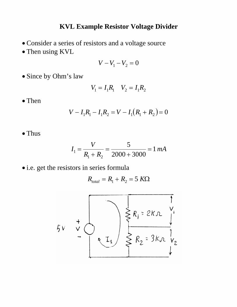
KVL Example Resistor Voltage Divider • Consider a series of resistors and a voltage source • Then using KVL
021 =−− VVV
• Since by Ohm’s law
212111 RIVRIV ==
• Then
( ) 02112111 =+−=−− RRIVRIRIV
• Thus
mARR
VI 130002000
5
211 =
+=
+=
• i.e. get the resistors in series formula
Ω=+= KRRRtotal 521
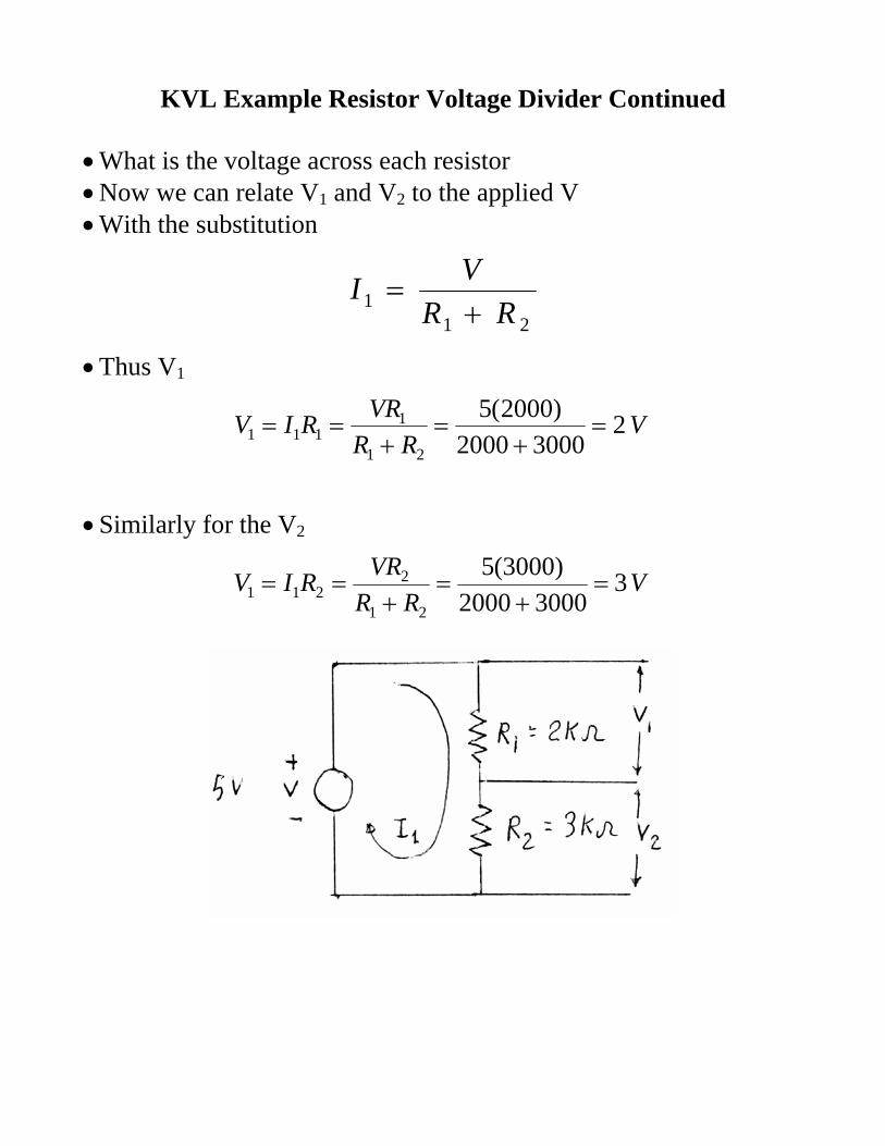
KVL Example Resistor Voltage Divider Continued • What is the voltage across each resistor • Now we can relate V1 and V2 to the applied V • With the substitution
211 RR
VI+
=
• Thus V1
VRR
VRRIV 230002000
)2000(5
21
1111 =
+=
+==
• Similarly for the V2
VRR
VRRIV 330002000
)3000(521
2211 =
+=
+==
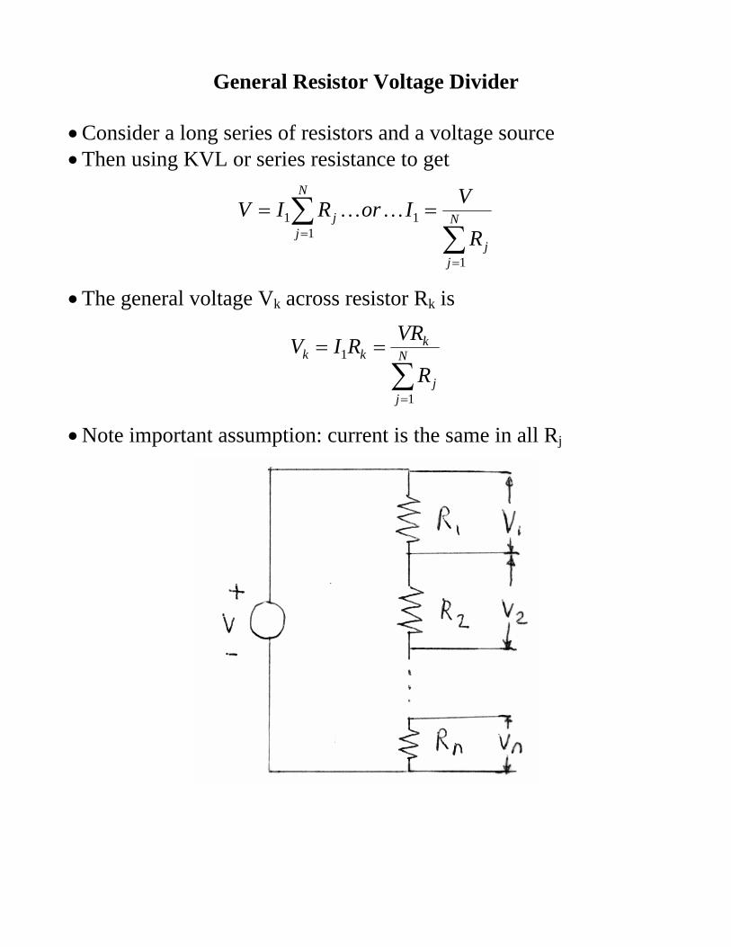
General Resistor Voltage Divider • Consider a long series of resistors and a voltage source • Then using KVL or series resistance to get
∑∑
=
=
== N
jj
N
jj
R
VIorRIV
1
11
1 KK
• The general voltage Vk across resistor Rk is
∑=
== N
jj
kkk
R
VRRIV
1
1
• Note important assumption: current is the same in all Rj
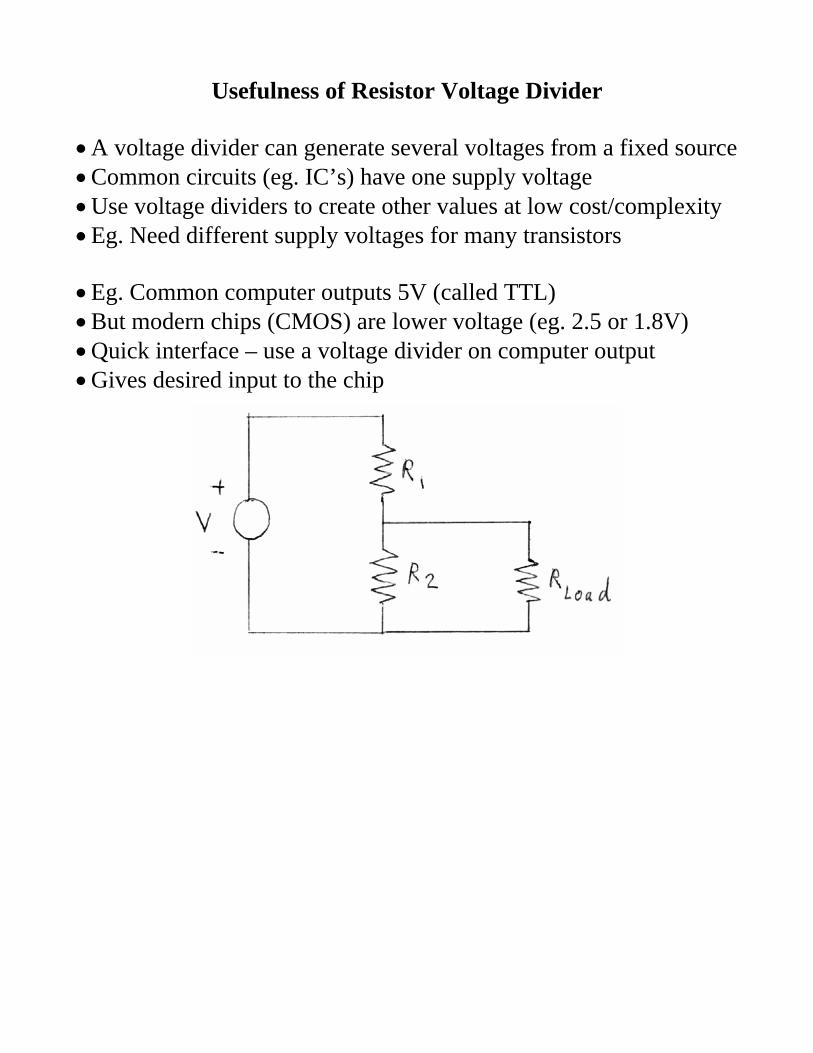
Usefulness of Resistor Voltage Divider • A voltage divider can generate several voltages from a fixed source • Common circuits (eg. IC’s) have one supply voltage • Use voltage dividers to create other values at low cost/complexity • Eg. Need different supply voltages for many transistors • Eg. Common computer outputs 5V (called TTL) • But modern chips (CMOS) are lower voltage (eg. 2.5 or 1.8V) • Quick interface – use a voltage divider on computer output • Gives desired input to the chip
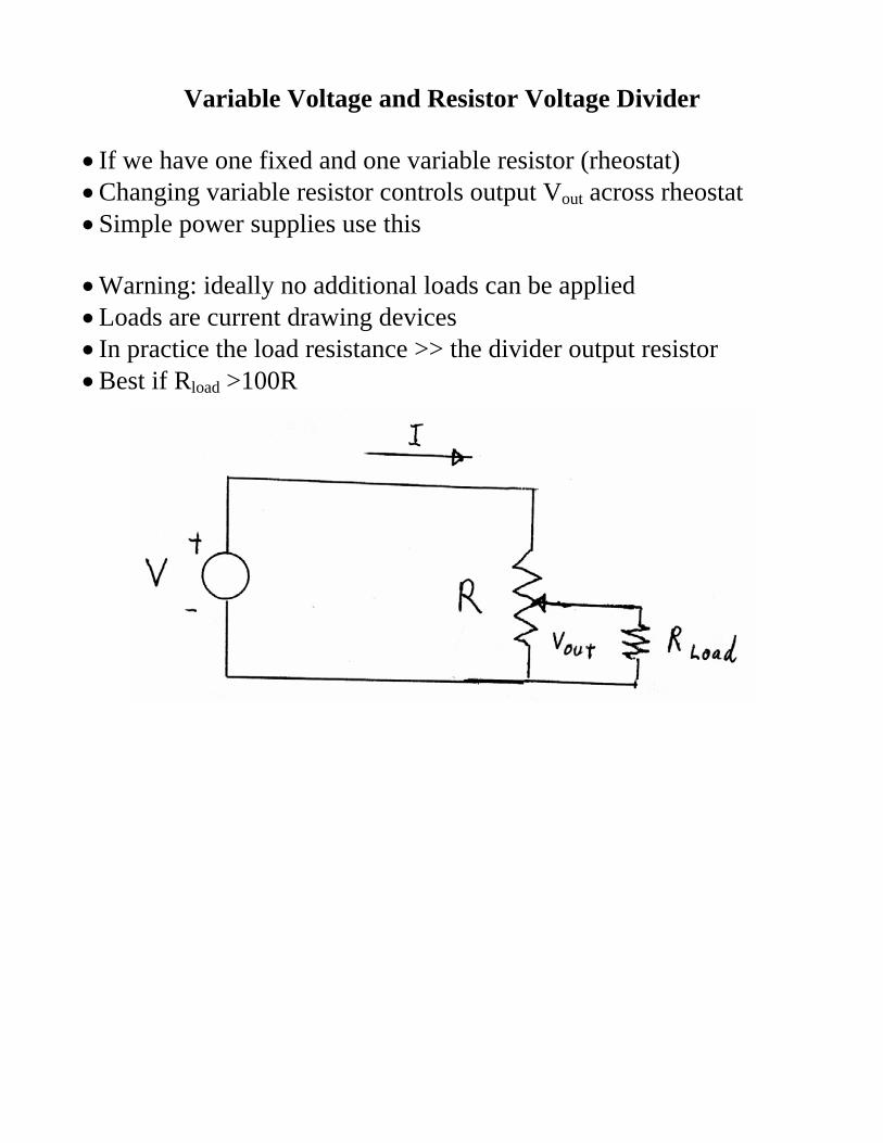
Variable Voltage and Resistor Voltage Divider • If we have one fixed and one variable resistor (rheostat) • Changing variable resistor controls output Vout across rheostat • Simple power supplies use this • Warning: ideally no additional loads can be applied • Loads are current drawing devices • In practice the load resistance >> the divider output resistor • Best if Rload >100R
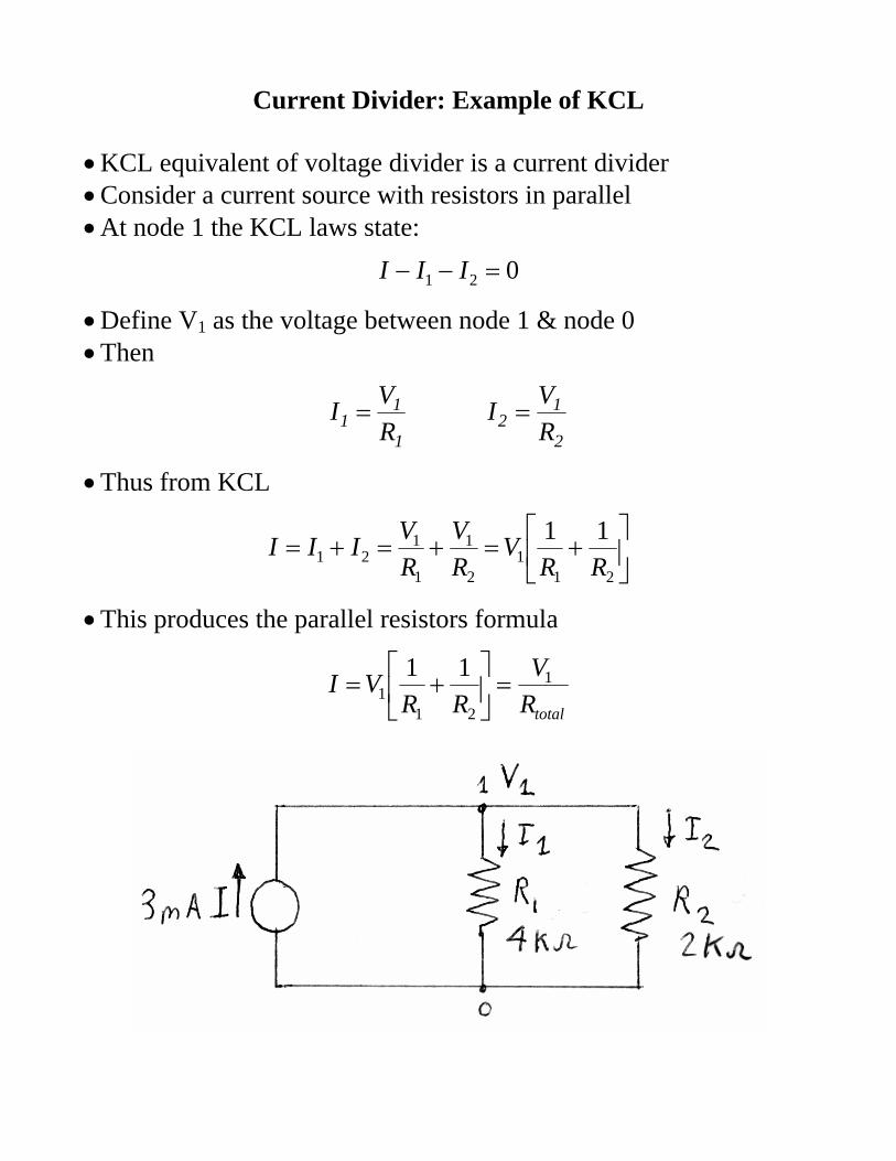
Current Divider: Example of KCL • KCL equivalent of voltage divider is a current divider • Consider a current source with resistors in parallel • At node 1 the KCL laws state:
021 =−− III
• Define V1 as the voltage between node 1 & node 0 • Then
2
12
1
11 R
VIRVI ==
• Thus from KCL
⎥⎦
⎤⎢⎣
⎡+=+=+=
211
2
1
1
121
11RR
VRV
RVIII
• This produces the parallel resistors formula
totalRV
RRVI 1
211
11=⎥
⎦
⎤⎢⎣
⎡+=
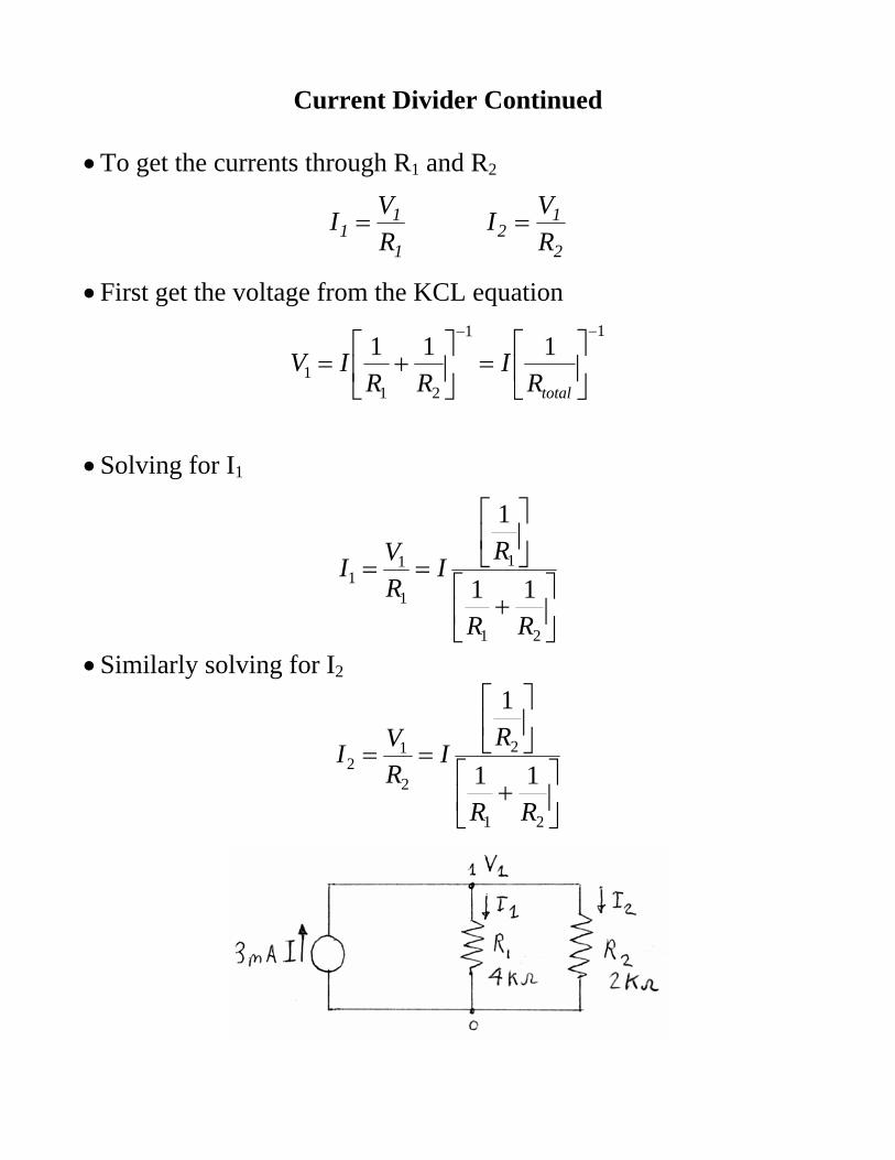
Current Divider Continued • To get the currents through R1 and R2
2
12
1
11 R
VIRVI ==
• First get the voltage from the KCL equation
11
211
111−−
⎥⎦
⎤⎢⎣
⎡=⎥
⎦
⎤⎢⎣
⎡+=
totalRI
RRIV
• Solving for I1
⎥⎦
⎤⎢⎣
⎡+
⎥⎦
⎤⎢⎣
⎡
==
21
1
1
11 11
1
RR
RIRVI
• Similarly solving for I2
⎥⎦
⎤⎢⎣
⎡+
⎥⎦
⎤⎢⎣
⎡
==
21
2
2
12 11
1
RR
RIRVI
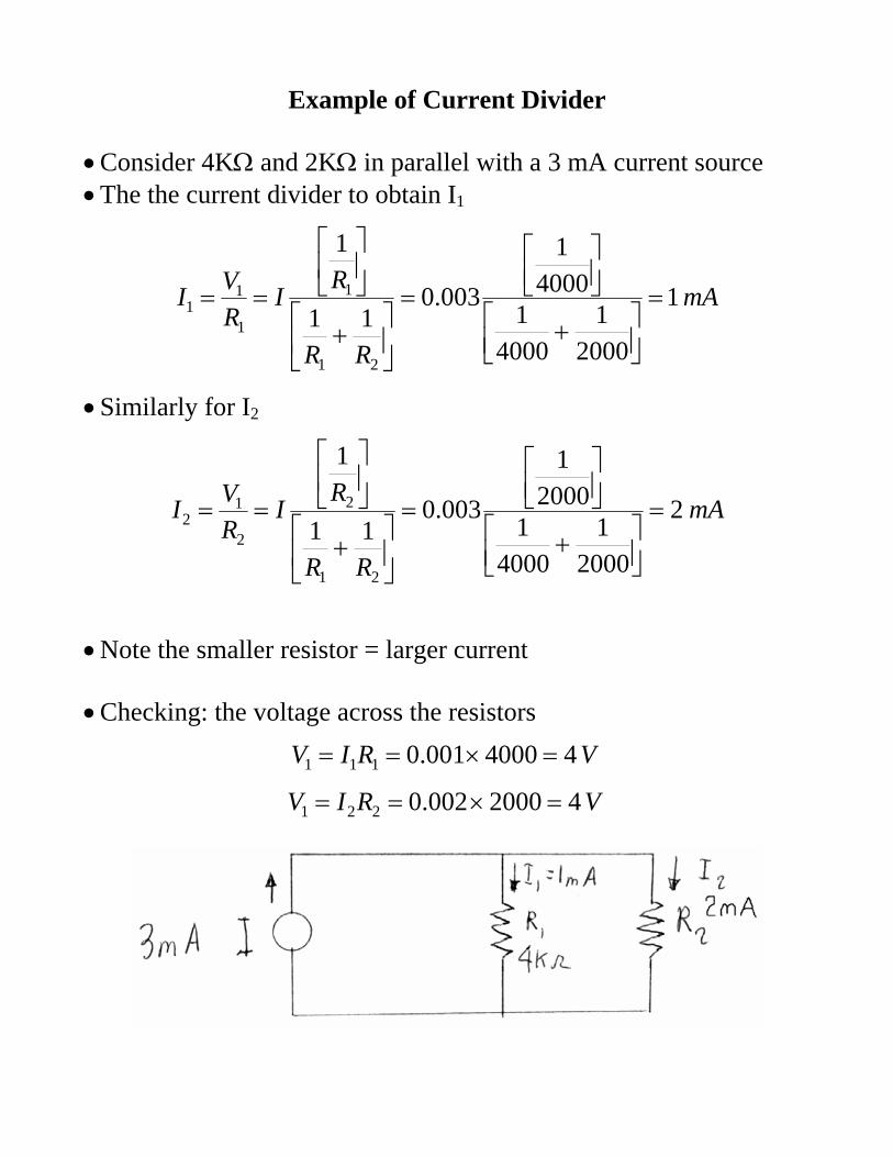
Example of Current Divider • Consider 4KΩ and 2KΩ in parallel with a 3 mA current source • The the current divider to obtain I1
mA
RR
RIRVI 1
20001
40001
40001
003.011
1
21
1
1
11 =
⎥⎦⎤
⎢⎣⎡ +
⎥⎦⎤
⎢⎣⎡
=
⎥⎦
⎤⎢⎣
⎡+
⎥⎦
⎤⎢⎣
⎡
==
• Similarly for I2
mA
RR
RIRVI 2
20001
40001
20001
003.011
1
21
2
2
12 =
⎥⎦⎤
⎢⎣⎡ +
⎥⎦⎤
⎢⎣⎡
=
⎥⎦
⎤⎢⎣
⎡+
⎥⎦
⎤⎢⎣
⎡
==
• Note the smaller resistor = larger current • Checking: the voltage across the resistors
VRIV 44000001.0111 =×==
VRIV 42000002.0221 =×==
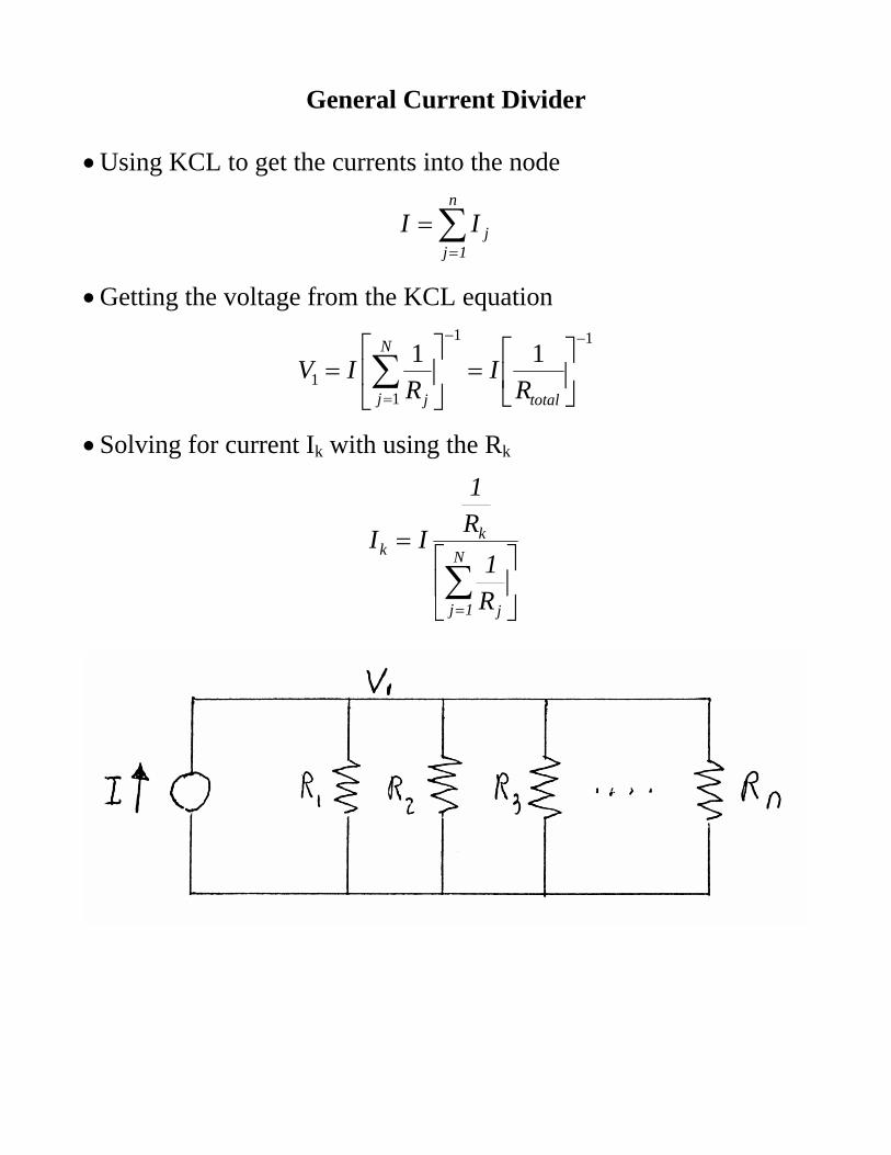
General Current Divider • Using KCL to get the currents into the node
∑=
=n
1jjII
• Getting the voltage from the KCL equation
11
11
11−−
=⎥⎦
⎤⎢⎣
⎡=⎥
⎦
⎤⎢⎣
⎡= ∑
total
N
j j RI
RIV
• Solving for current Ik with using the Rk
⎥⎦
⎤⎢⎣
⎡=
∑=
N
1j j
kk
R1
R1
II
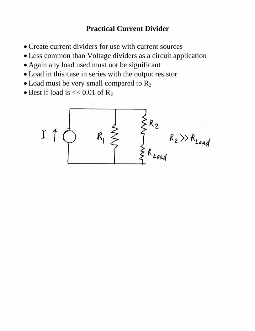
Practical Current Divider • Create current dividers for use with current sources • Less common than Voltage dividers as a circuit application • Again any load used must not be significant • Load in this case in series with the output resistor • Load must be very small compared to R2 • Best if load is << 0.01 of R2
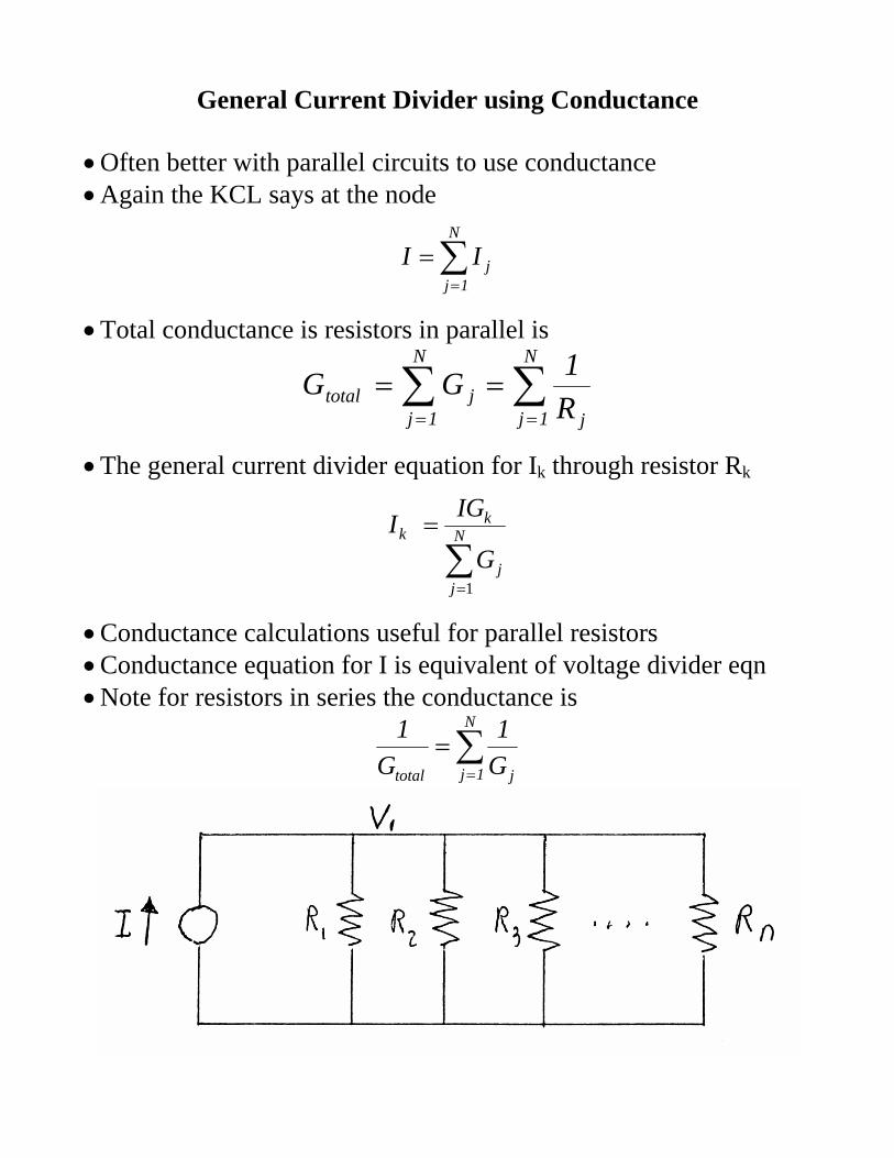
General Current Divider using Conductance • Often better with parallel circuits to use conductance • Again the KCL says at the node
∑=
=N
1jjII
• Total conductance is resistors in parallel is
∑∑==
==N
1j j
N
1jjtotal R
1GG
• The general current divider equation for Ik through resistor Rk
∑=
= N
jj
kk
G
IGI
1
• Conductance calculations useful for parallel resistors • Conductance equation for I is equivalent of voltage divider eqn • Note for resistors in series the conductance is
∑=
=N
1j jtotal G1
G1
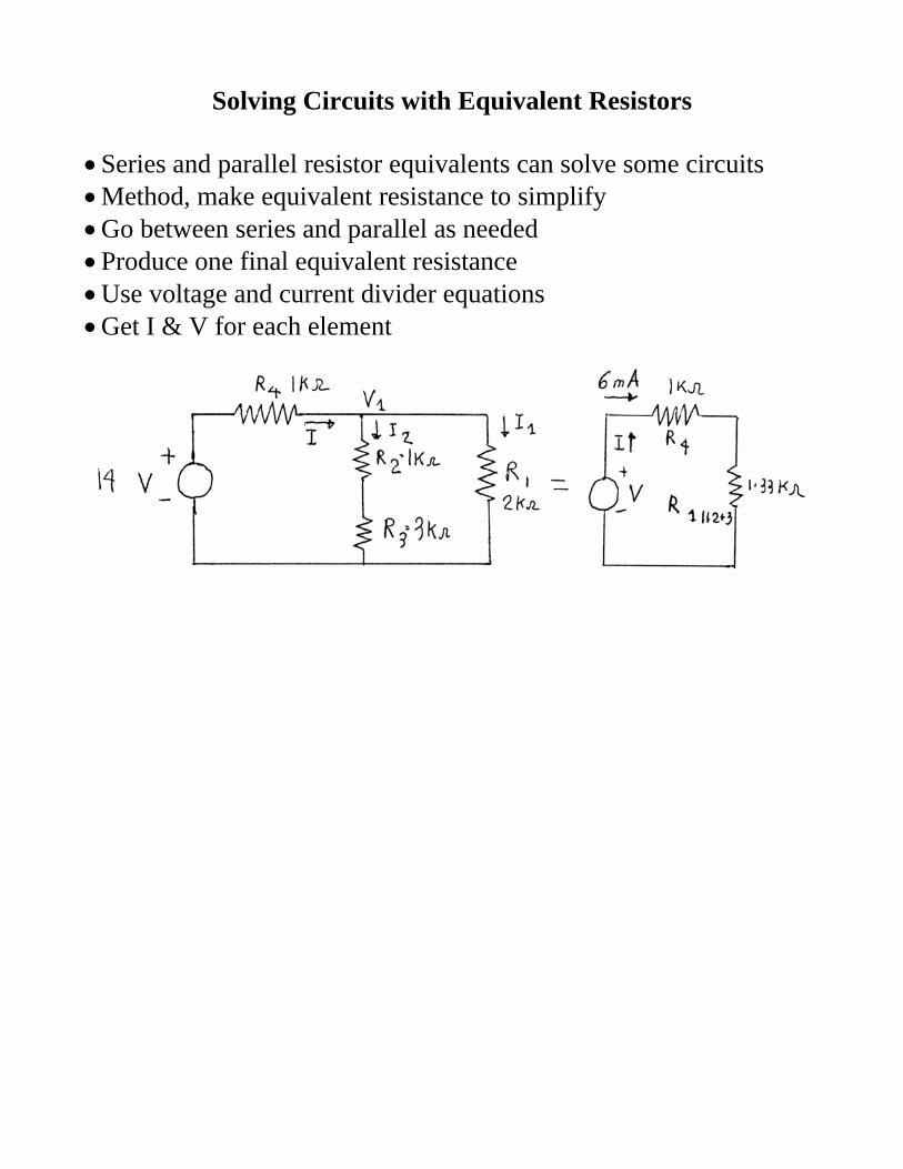
Solving Circuits with Equivalent Resistors • Series and parallel resistor equivalents can solve some circuits • Method, make equivalent resistance to simplify • Go between series and parallel as needed • Produce one final equivalent resistance • Use voltage and current divider equations • Get I & V for each element
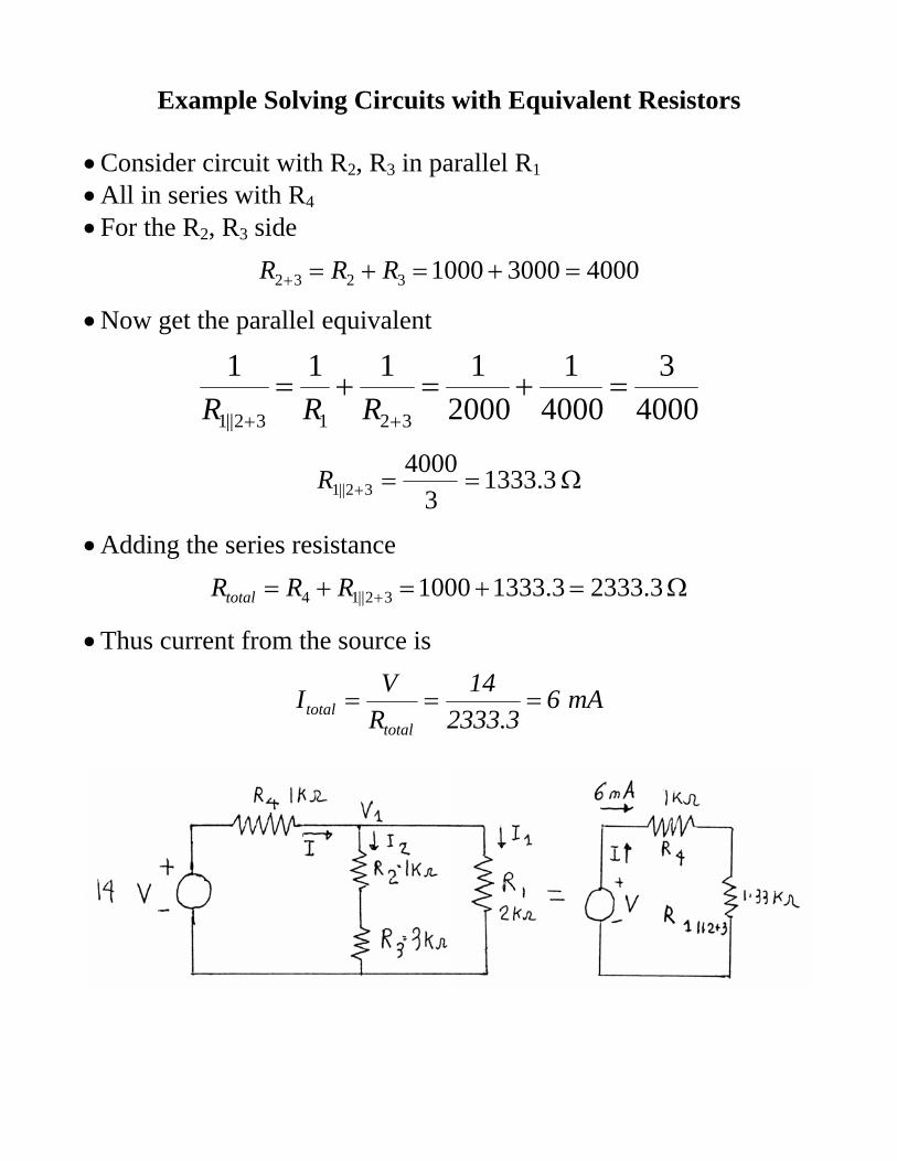
Example Solving Circuits with Equivalent Resistors • Consider circuit with R2, R3 in parallel R1 • All in series with R4 • For the R2, R3 side
4000300010003232 =+=+=+ RRR
• Now get the parallel equivalent
40003
40001
20001111
32132||1
=+=+=++ RRR
Ω==+ 3.13333
400032||1R
• Adding the series resistance
Ω=+=+= + 3.23333.1333100032||14 RRRtotal
• Thus current from the source is
mA63.2333
14RVItotal
total ===
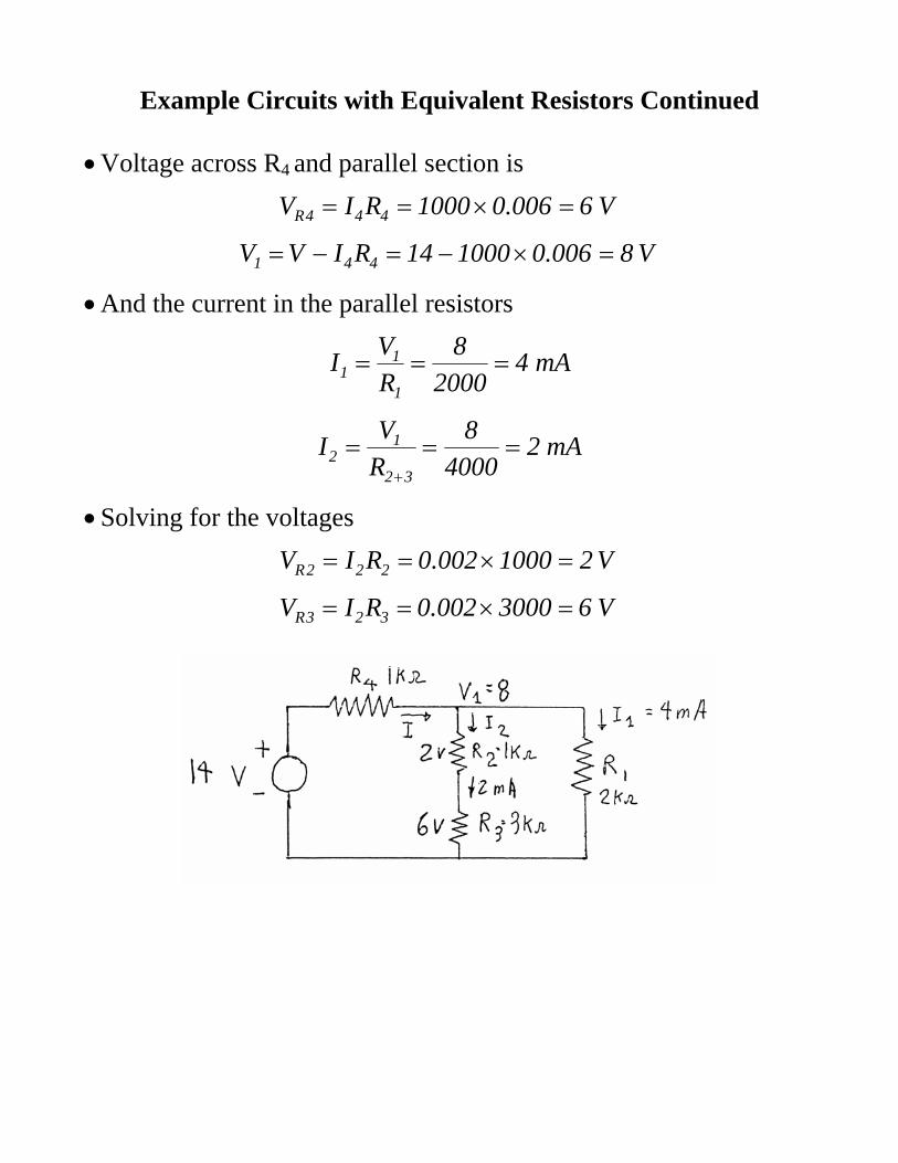
Example Circuits with Equivalent Resistors Continued • Voltage across R4 and parallel section is
V6006.01000RIV 444R =×==
V8006.0100014RIVV 441 =×−=−=
• And the current in the parallel resistors
mA42000
8RVI
1
11 ===
mA24000
8RVI
32
12 ===
+
• Solving for the voltages
V21000002.0RIV 222R =×==
V63000002.0RIV 323R =×==
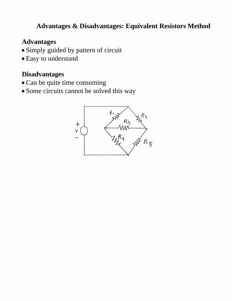
Advantages & Disadvantages: Equivalent Resistors Method Advantages • Simply guided by pattern of circuit • Easy to understand Disadvantages • Can be quite time consuming • Some circuits cannot be solved this way
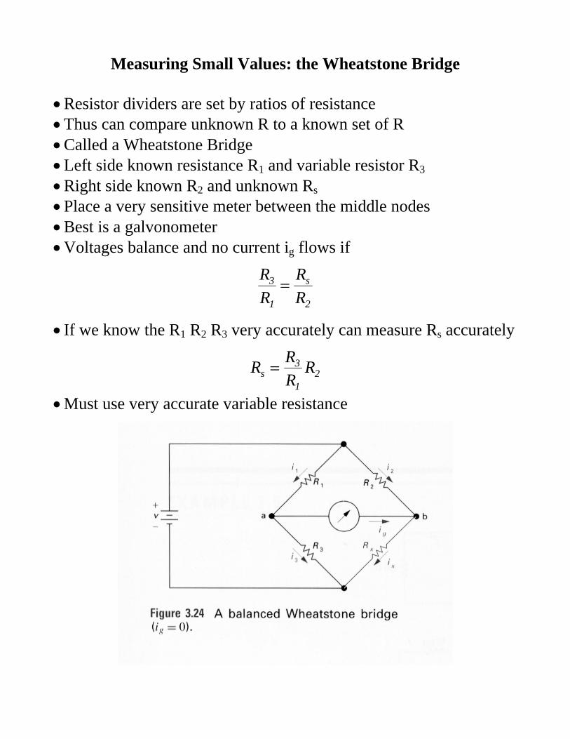
Measuring Small Values: the Wheatstone Bridge • Resistor dividers are set by ratios of resistance • Thus can compare unknown R to a known set of R • Called a Wheatstone Bridge • Left side known resistance R1 and variable resistor R3 • Right side known R2 and unknown Rs • Place a very sensitive meter between the middle nodes • Best is a galvonometer • Voltages balance and no current ig flows if
2
s
1
3
RR
RR
=
• If we know the R1 R2 R3 very accurately can measure Rs accurately
21
3s R
RRR =
• Must use very accurate variable resistance
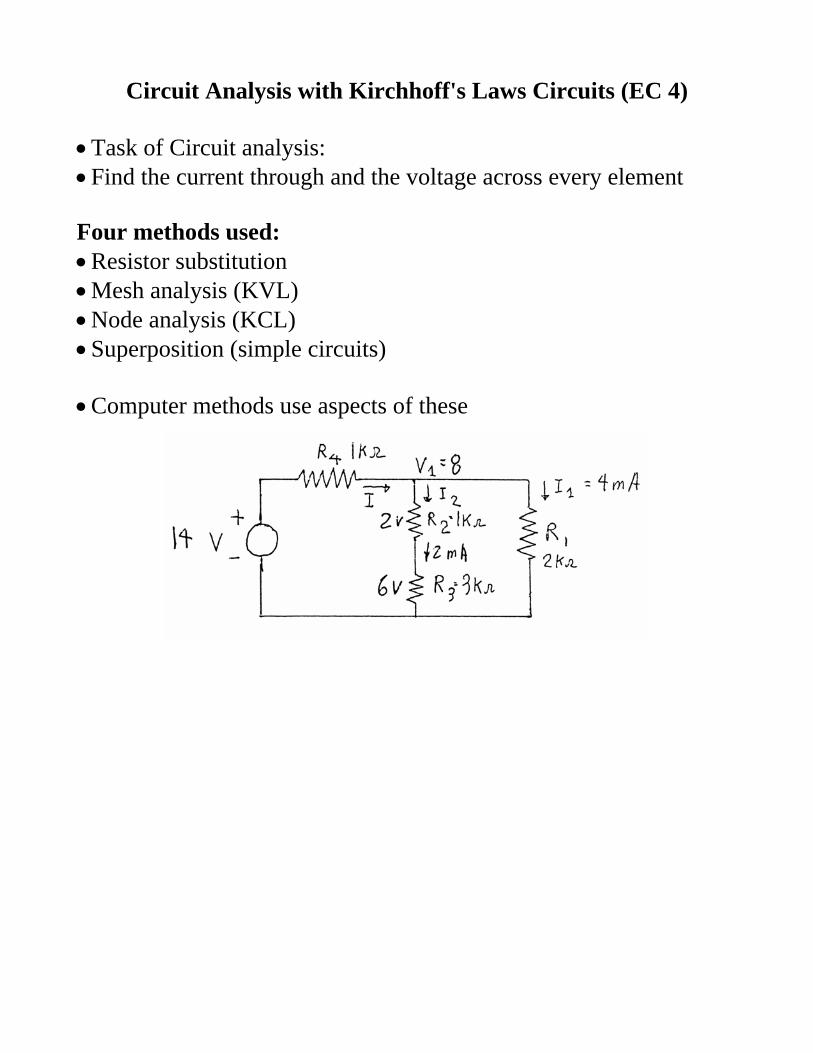
Circuit Analysis with Kirchhoff's Laws Circuits (EC 4) • Task of Circuit analysis: • Find the current through and the voltage across every element Four methods used: • Resistor substitution • Mesh analysis (KVL) • Node analysis (KCL) • Superposition (simple circuits) • Computer methods use aspects of these

Circuit Definitions • Node: point where several current paths meet:
• Branch: a current path connecting only two nodes • Branch contains 1 or more devices eg. resistors • Note: a node may have many branch connections
• If 2 nodes are connected by a wire • Then combine them into a single node
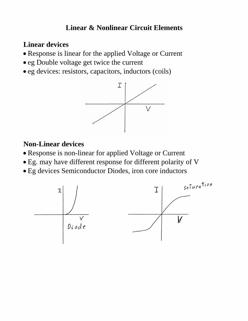
Linear & Nonlinear Circuit Elements Linear devices • Response is linear for the applied Voltage or Current • eg Double voltage get twice the current • eg devices: resistors, capacitors, inductors (coils)
Non-Linear devices • Response is non-linear for applied Voltage or Current • Eg. may have different response for different polarity of V • Eg devices Semiconductor Diodes, iron core inductors
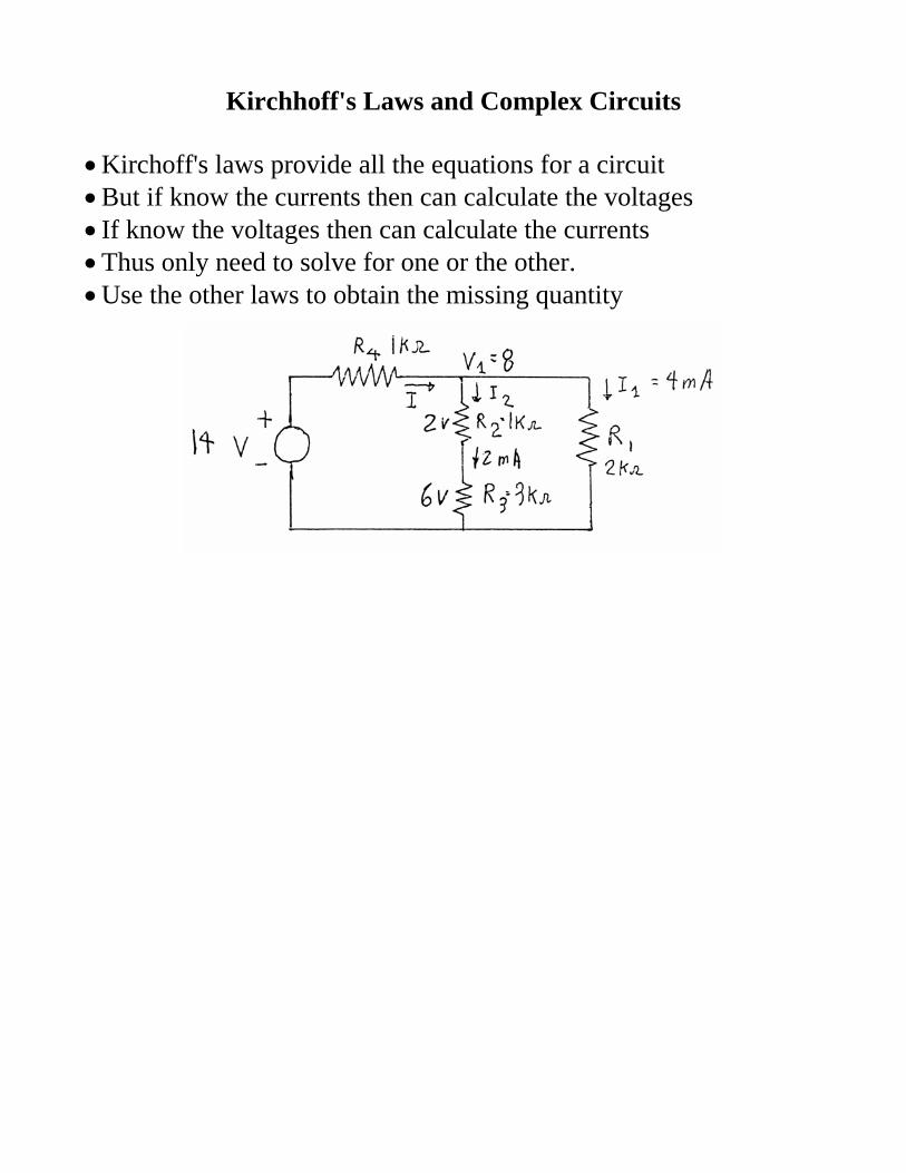
Kirchhoff's Laws and Complex Circuits • Kirchoff's laws provide all the equations for a circuit • But if know the currents then can calculate the voltages • If know the voltages then can calculate the currents • Thus only need to solve for one or the other. • Use the other laws to obtain the missing quantity