KON 100-115 - unicalkazan.euunicalkazan.eu/files/KON-100-115-ismertet--angolul_rev1.pdf · kon...
12
KON 100-115 MODULATING CONDENSING BOILER WITH LOW NOX PREMIX BURNER FOR OUTDOOR INSTALLATION (IPX5D) OUTPUT RANGE from 99.5 to 920 kW in battery (115kW x 8) WORKING TEMPERATURE No temperature limit on the return (max. Δt 20K) For outdoor installation in partially protected places: - 15C (with dedicated kits and protections) SUPPLY Natural Gas or LPG MODELS KON 100 KON 115 SEASONAL EFFICIENCY A ENERGETIC CLASS Ex Directive 92/42 Wall hung with optional dedicated supporting kit - available in battery (up to 8 for a total of 920 kW)
Transcript of KON 100-115 - unicalkazan.euunicalkazan.eu/files/KON-100-115-ismertet--angolul_rev1.pdf · kon...
KON 100-115
MODULATING CONDENSING BOILER WITH LOW NOX PREMIX BURNERFOR OUTDOOR INSTALLATION (IPX5D)
OUTPUT RANGE from 99.5 to 920 kW in battery (115kW x8)
WORKING TEMPERATURENo temperature limit on the return (max. Δt 20K)
For outdoor installation in partially protected places: - 15C (with dedicated kits and protections)
SUPPLY Natural Gas or LPG
MODELS KON 100 KON 115
SEASONAL EFFICIENCYA
ENERGETIC CLASSEx Directive 92/42
Wall hung with optional dedicated supporting kit - available in battery (up to 8 for a total of 920 kW)
KON 100-115 Condensing boilers
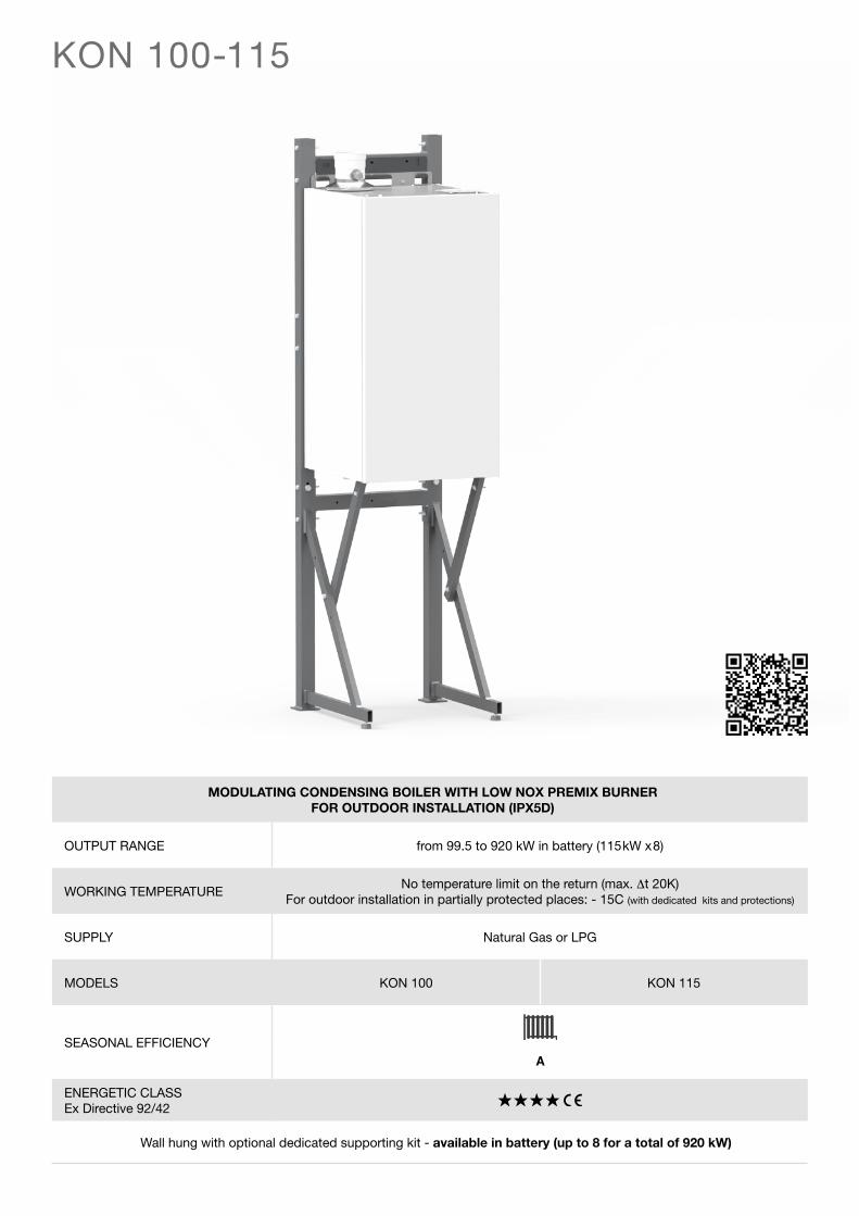
MAIN COMPONENTS
PRODUCT PLUS VALUES
FLUE GAS EXAUST Ø100
FLUE COMBUSTION
FLUE GAS PRESSURE SWITCH
BURNER
IGNITION ELECTRODE
EXCANGER SAFETY THERMOSTAT
IGNITION TRASFORMER
SMOKE THERMOSTAT
GAS VALVE
GAS MIN PRESSURE SWITCH
MODULATING PUMP
BOILER DRAIN
CONDENSATION DRAIN TRAP
RETURN TEMPERATURESENSOR
WATER DEFICIENCYPRESSURE SWITCH
ALUMINIUM HEATEXCHANGER/CAPACITOR
SAFETY THERMOSTAT
SENSOR FLOW GENERAL
MANUAL VENT VALVE
DETECTION ELECTRODE
VENT VALVE
AIR INTAKE
CERTIFICATION IN OUTPUT RANGE it is possible to have the customization of the input
WALL HUNG with metallic load bearing structure (optional)
COMPACTNESS: dimensions (WxHxD): 50x95x48 cm
PERFORMANCES ErP class A
RENDIMENTO up to 108,8% (ex Directive 92/42) ηs=94% according to ErP Directive
EMISSIONS: Low NOx Class 5
ISOLATION DEGREE IPX5D can be installed outdoor in partially protected place (with antifreeze kit)
BODY STRUCTURE with double furnace
BOILER BODY in Al/Si/Mg low water content - 100% wet surfaces
EXCELLENT THERMAL EXCHANGE Sophisticated cooling circuit with triple water circulation on 3
vertical columns
SIMPLE CONSTRUCTION for a quick and economic servicing
DURATION thanks to the multi-year Unical experience in the metallurgy the
body is guaranteed 5 years
RELIABILITY thanks to the optimized circulation that avoids thermal overcharges;
heat exchanger carefully designed, high efficiency modulating pimp, NTC control sensors
EFFICIENCY GUARANTEED FOR LONG TIME thanks to the absence of scaling
ACCESSORIES (optional) - PRIMARY RING, with MIXING HEADER / PLATE HEAT EXCHANGER - ADDITIONAL SAFETY DEVICES KIT - DIFFERENTIAL PRESSURE SWITCH with fittings - CONTROL PANEL BOARD HSCP - MULTI-FUNCTION MODULE SHC (for zones control) - NTC SENSOR FOR SHC MODUL - MULTI-FUNCTION MODULES FEEDER - PT1000 SENSOR for management of solar collectors - SIPHON HEATING KIT - KIT OF RESISTANCES FOR LOW TEMPERATURES - ACIDIC CONDENSATE INHIBITORS
EXPANDABLE IN CASCATE (up to 8 modules)
GAS FEEDING PIPES available (optional)
Available, on request, PLATE HEAT EXCHANGERS up to 4 modules in battery
KON 100-115Condensing boilers
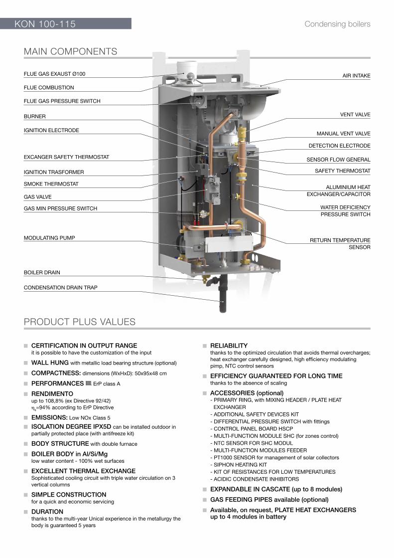
DIMENSIONS
DIMENSIONS WITH SUPPORTING FRAME (optional)
950
20 500
103
312
85
118 285
500
79 71,5 144,5 119 86
305
195
97
69
76
347,5
260
FRONT VIEW LEFT SIDE VIEW BACK VIEW VIEW FROM BELOW
VIEW FROM ABOVE
ScondGR
A
S
M
Rs
526 556
1944
Key:
G - Gas inlet G1”
M - Mandata impianto riscaldamento G1 ¼”
R - Heating system return G1 ¼”
Rs - Boiler drain
Scond - Condensation drain Ø 32
S - Flue gas exaust Ø 100
A - Air intake Ø 80-100
KONNet Weight
kg
Gross Weight(with packaging)
kg
100-115 96 120
KON 100-115 Condensing boilers
CONTROL PANEL (std. supplied)
KIT CONTROL PANEL (optional)
SHC - MULTI-FUNCTION MODULE - HEATING CIRCUITS MANAGEMENT (optional)
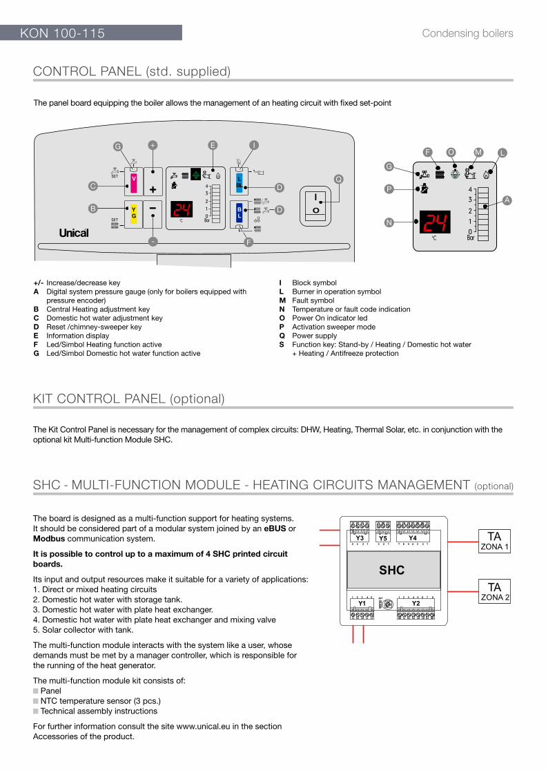
The panel board equipping the boiler allows the management of an heating circuit with fixed set-point
The Kit Control Panel is necessary for the management of complex circuits: DHW, Heating, Thermal Solar, etc. in conjunction with the optional kit Multi-function Module SHC.
The board is designed as a multi-function support for heating systems.It should be considered part of a modular system joined by an eBUS or Modbus communication system.
It is possible to control up to a maximum of 4 SHC printed circuit boards.
Its input and output resources make it suitable for a variety of applications:1. Direct or mixed heating circuits2. Domestic hot water with storage tank.3. Domestic hot water with plate heat exchanger.4. Domestic hot water with plate heat exchanger and mixing valve5. Solar collector with tank.
The multi-function module interacts with the system like a user, whose demands must be met by a manager controller, which is responsible for the running of the heat generator.
The multi-function module kit consists of: Panel NTC temperature sensor (3 pcs.) Technical assembly instructions
For further information consult the site www.unical.eu in the section Accessories of the product.
G
C
B
-
D
D
F
Q
N
P
G
A
E I+F O M L
+/- Increase/decrease keyA Digital system pressure gauge (only for boilers equipped with
pressure encoder)B Central Heating adjustment keyC Domestic hot water adjustment keyD Reset /chimney-sweeper keyE Information displayF Led/Simbol Heating function activeG Led/Simbol Domestic hot water function active
I Block symbolL Burner in operation symbolM Fault symbolN Temperature or fault code indicationO Power On indicator ledP Activation sweeper modeQ Power supplyS Function key: Stand-by / Heating / Domestic hot water + Heating / Antifreeze protection
KON 100-115Condensing boilers
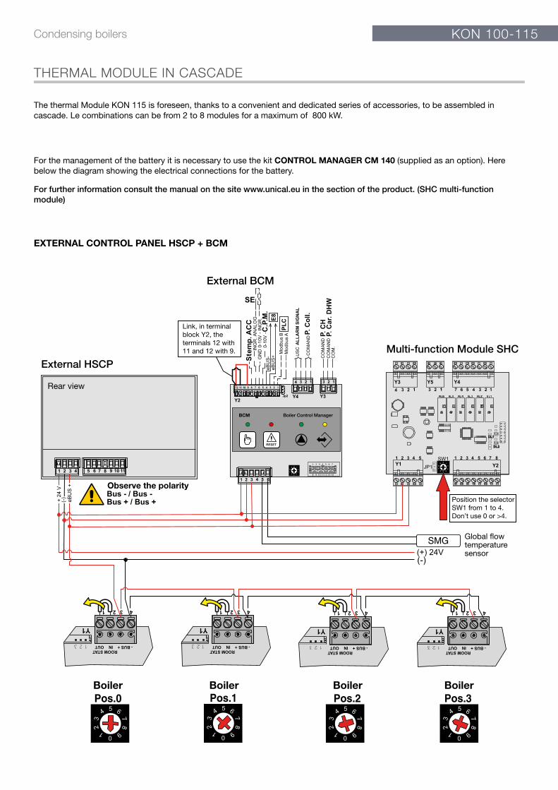
The thermal Module KON 115 is foreseen, thanks to a convenient and dedicated series of accessories, to be assembled in cascade. Le combinations can be from 2 to 8 modules for a maximum of 800 kW.
For the management of the battery it is necessary to use the kit CONTROL MANAGER CM 140 (supplied as an option). Here below the diagram showing the electrical connections for the battery.
EXTERNAL CONTROL PANEL HSCP + BCM
Observe the polarity
External BCM
External HSCPMulti-function Module SHC
Boiler Boiler Boiler Boiler
Rear view
Link, in terminal block Y2, the terminals 12 with 11 and 12 with 9.
Position the selector SW1 from 1 to 4.Don’t use 0 or >4.
Global flowtemperaturesensor
THERMAL MODULE IN CASCADE
For further information consult the manual on the site www.unical.eu in the section of the product. (SHC multi-function module)
KON 100-115 Condensing boilers
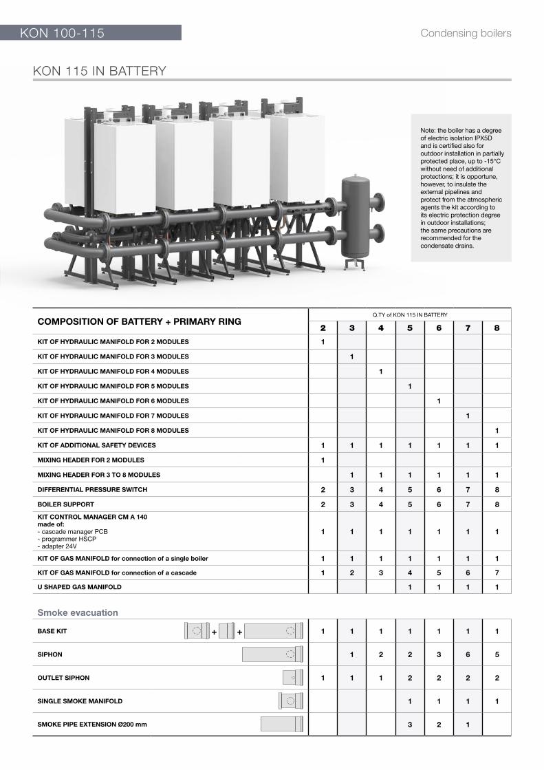
COMPOSITION OF BATTERY + PRIMARY RINGQ.TY of KON 115 IN BATTERY
2 3 4 5 6 7 8
KIT OF HYDRAULIC MANIFOLD FOR 2 MODULES 1
KIT OF HYDRAULIC MANIFOLD FOR 3 MODULES 1
KIT OF HYDRAULIC MANIFOLD FOR 4 MODULES 1
KIT OF HYDRAULIC MANIFOLD FOR 5 MODULES 1
KIT OF HYDRAULIC MANIFOLD FOR 6 MODULES 1
KIT OF HYDRAULIC MANIFOLD FOR 7 MODULES 1
KIT OF HYDRAULIC MANIFOLD FOR 8 MODULES 1
KIT OF ADDITIONAL SAFETY DEVICES 1 1 1 1 1 1 1
MIXING HEADER FOR 2 MODULES 1
MIXING HEADER FOR 3 TO 8 MODULES 1 1 1 1 1 1
DIFFERENTIAL PRESSURE SWITCH 2 3 4 5 6 7 8
BOILER SUPPORT 2 3 4 5 6 7 8
KIT CONTROL MANAGER CM A 140made of:- cascade manager PCB- programmer HSCP- adapter 24V
1 1 1 1 1 1 1
KIT OF GAS MANIFOLD for connection of a single boiler 1 1 1 1 1 1 1
KIT OF GAS MANIFOLD for connection of a cascade 1 2 3 4 5 6 7
U SHAPED GAS MANIFOLD 1 1 1 1
Smoke evacuation
BASE KIT +
+
1 1 1 1 1 1 1
SIPHON 1 2 2 3 6 5
OUTLET SIPHON 1 1 1 2 2 2 2
SINGLE SMOKE MANIFOLD 1 1 1 1
SMOKE PIPE EXTENSION Ø200 mm 3 2 1
KON 115 IN BATTERY
Note: the boiler has a degree of electric isolation IPX5D and is certified also for outdoor installation in partially protected place, up to -15°C without need of additional protections; it is opportune, however, to insulate the external pipelines and protect from the atmospheric agents the kit according to its electric protection degree in outdoor installations; the same precautions are recommended for the condensate drains.

KON 100-115Condensing boilers
1400
324Ø
200
2300
DN
100
327
1460
≤1000
825
1 2
USCITAFUMI Ø 200
324
1400
324
Ø 2
00
2300
DN
100
327
1460
≤1000
825
1 2
SMOKE OUTLETØ 200
324
DIMENSIONS OF A BATTERY OF TWO KON 115
Operational data KON 100 KON 115
Minimum Input on N.C.V. Qmin kW 20 20
Nominal Input on N.C.V. Qn kW 199 230
Nominal Output (60/80°C) Pn kW 197.6 223
Nominal Output (30/50°C) Pcond kW 210 240.6
Operational data KON 100 KON 115
Minimum Input on N.C.V. Qmin kW 20 20
Nominal Input on N.C.V. Qn kW 298.5 345
Nominal Output (60/80°C) Pn kW 296.4 334.5
Nominal Output (30/50°C) Pcond kW 315 360.9
Operational data KON 100 KON 115
Minimum Input on N.C.V. Qmin kW 20 20
Nominal Input on N.C.V. Qn kW 398 460
Nominal Output (60/80°C) Pn kW 395.2 446
Nominal Output (30/50°C) Pcond kW 420 481.2
DIMENSIONS OF A BATTERY OF THREE KON 115
DIMENSIONS OF A BATTERY OF FOUR KON 115
2180
324 231
2220
825
DN
10032
7
2430
Ø 2
00
≤1000
1 2 3
324 231732,5
USCITAFUMI Ø 200
2180
324 231
2220
825
DN
10032
7
2430
Ø 2
00
≤1000
1 2 3
324 231732,5
SMOKEOUTLET Ø 200
2900
Ø 2
00
324 231 231
2920
324825 732,5 732,5
231 231
DN
100
327
2480
≤1000
1 2 3 4
US
CIT
AF
UM
I Ø 2
00
2900
Ø 2
00
324 231 231
2920
324825 732,5 732,5
231 231
DN
100
327
2480
≤1000
1 2 3 4
SM
OK
EO
UT
LET
Ø 2
00
Warning: The flue ducts in plastic material (PPS) are suitable only for Indoor installations.
Warning: The flue ducts in plastic material (PPS) are suitable only for Indoor installations.
Warning: The flue ducts in plastic material (PPS) are suitable only for Indoor installations.
KON 100-115 Condensing boilers
Operational data KON 100 KON 115
Minimum Inputon N.C.V. Qmin
kW 20 20
Nominal Inputon N.C.V. Qn
kW 497.5 575
Nominal Output(60/80°C) Pn
kW 494.0 557.5
Nominal Output(30/50°C) Pcond
kW 525.0 601.5
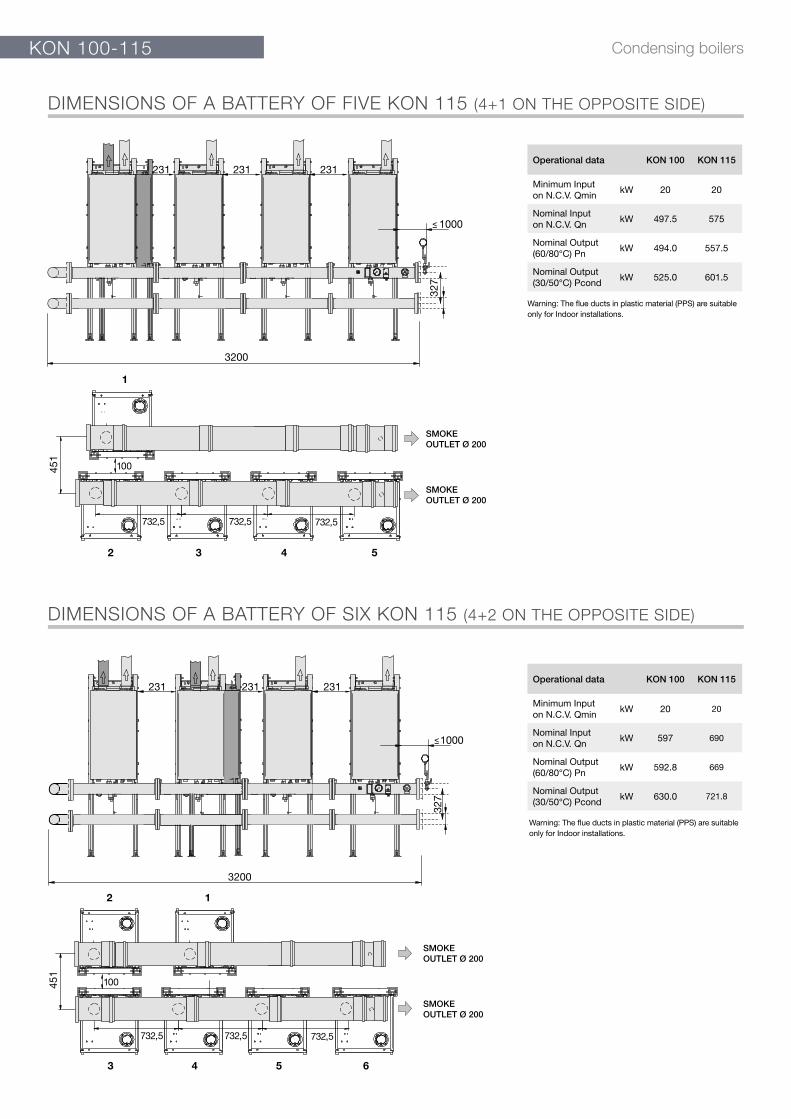
DIMENSIONS OF A BATTERY OF SIX KON 115 (4+2 ON THE OPPOSITE SIDE)
231
3200
1000
327
732,5 732,5 732,5
1
2 3 4 5
231 231
451
SMOKEOUTLET Ø 200
SMOKEOUTLET Ø 200
100
3200
231 231 231
1000
327
12
3 4 5 6
732,5 732,5 732,5
SMOKEOUTLET Ø 200
SMOKEOUTLET Ø 200
451
100
DIMENSIONS OF A BATTERY OF FIVE KON 115 (4+1 ON THE OPPOSITE SIDE)
Warning: The flue ducts in plastic material (PPS) are suitable only for Indoor installations.
Warning: The flue ducts in plastic material (PPS) are suitable only for Indoor installations.
Operational data KON 100 KON 115
Minimum Inputon N.C.V. Qmin
kW 20 20
Nominal Inputon N.C.V. Qn
kW 597 690
Nominal Output(60/80°C) Pn
kW 592.8 669
Nominal Output(30/50°C) Pcond
kW 630.0 721.8
KON 100-115Condensing boilers
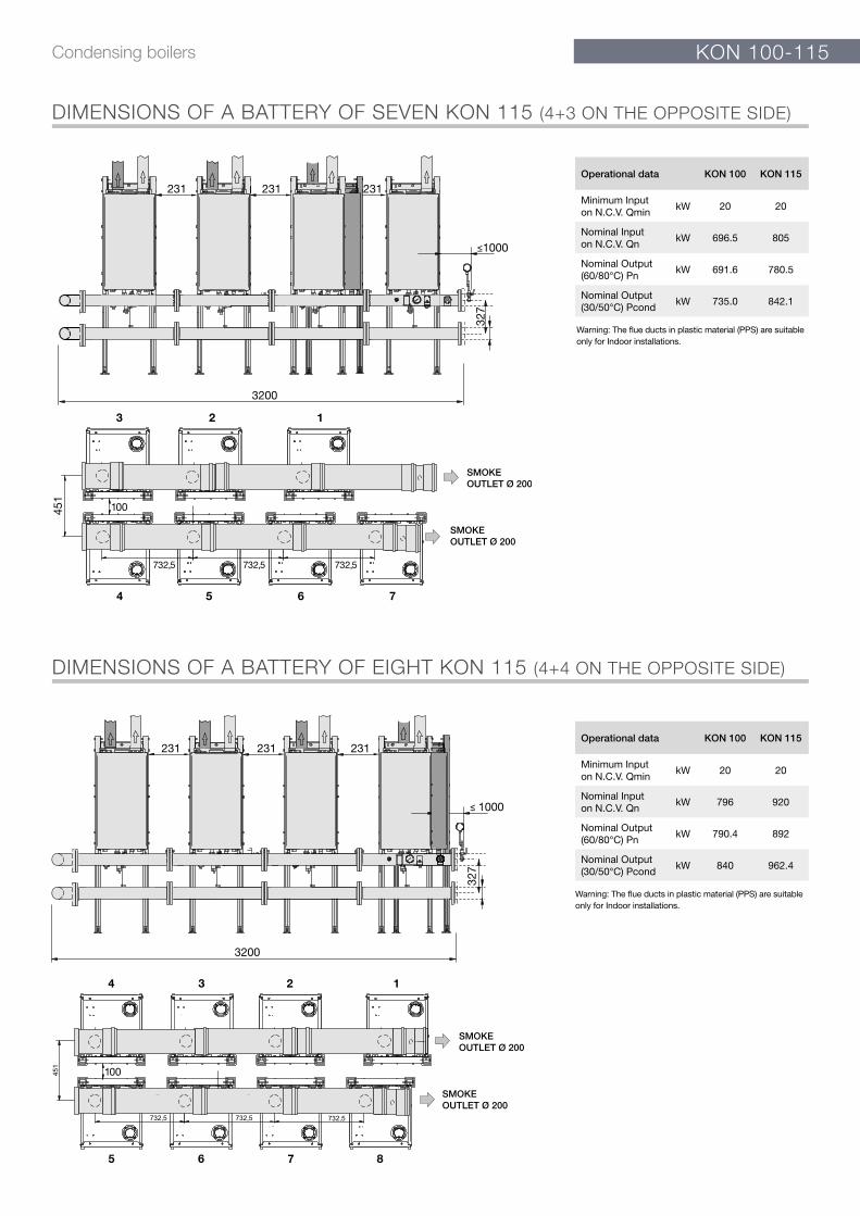
Operational data KON 100 KON 115
Minimum Inputon N.C.V. Qmin
kW 20 20
Nominal Inputon N.C.V. Qn
kW 696.5 805
Nominal Output(60/80°C) Pn
kW 691.6 780.5
Nominal Output(30/50°C) Pcond
kW 735.0 842.1
DIMENSIONS OF A BATTERY OF SEVEN KON 115 (4+3 ON THE OPPOSITE SIDE)
DIMENSIONS OF A BATTERY OF EIGHT KON 115 (4+4 ON THE OPPOSITE SIDE)
231
1000
123
6 754
3200
231 231
327
732,5 732,5 732,5
451
SMOKEOUTLET Ø 200
SMOKEOUTLET Ø 200
100
1234
8765
1000
3200
327
231 231 231
SMOKEOUTLET Ø 200
SMOKEOUTLET Ø 200
100
Warning: The flue ducts in plastic material (PPS) are suitable only for Indoor installations.
Warning: The flue ducts in plastic material (PPS) are suitable only for Indoor installations.
Operational data KON 100 KON 115
Minimum Inputon N.C.V. Qmin
kW 20 20
Nominal Inputon N.C.V. Qn
kW 796 920
Nominal Output(60/80°C) Pn
kW 790.4 892
Nominal Output(30/50°C) Pcond
kW 840 962.4
KON 100-115 Condensing boilers
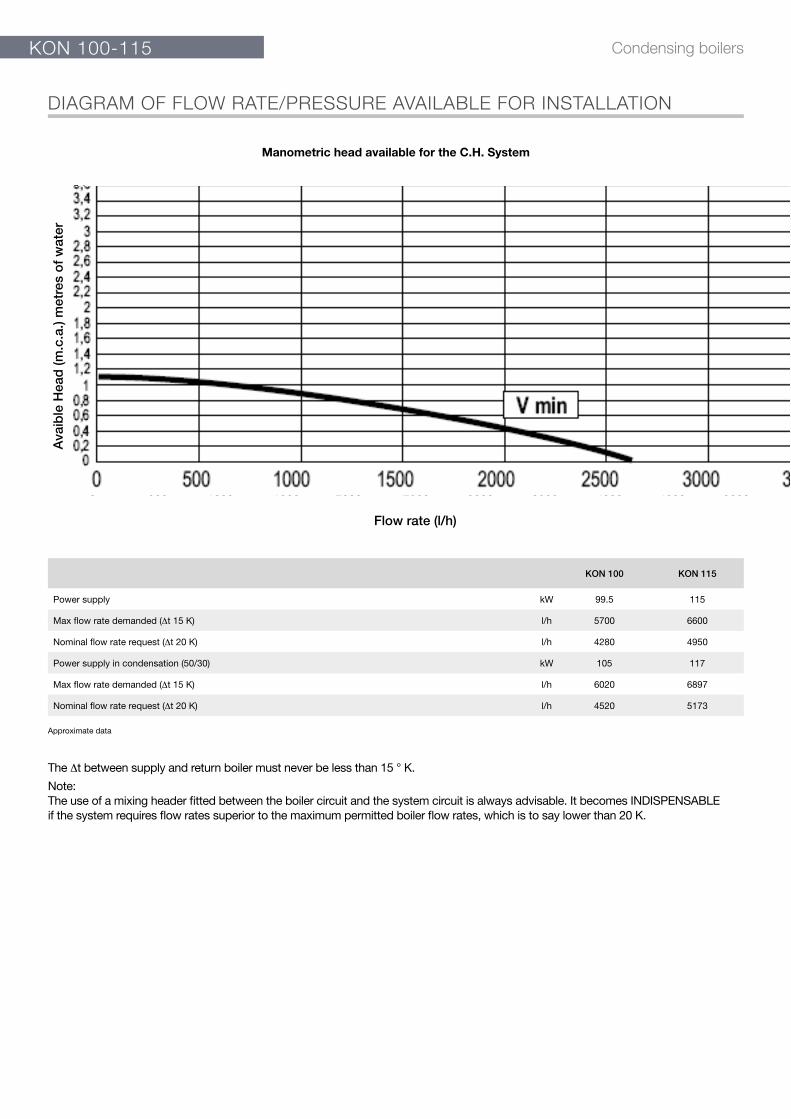
DIAGRAM OF FLOW RATE/PRESSURE AVAILABLE FOR INSTALLATION
KON 100 KON 115
Power supply kW 99.5 115
Max flow rate demanded (Δt 15 K) l/h 5700 6600
Nominal flow rate request (Δt 20 K) l/h 4280 4950
Power supply in condensation (50/30) kW 105 117
Max flow rate demanded (Δt 15 K) l/h 6020 6897
Nominal flow rate request (Δt 20 K) l/h 4520 5173
Flow rate (l/h)
Ava
ible
Hea
d (m
.c.a
.) m
etre
s o
f w
ater
0 500 1000 1500 2000 2500 3000 3500 4000 4500 5000
The Δt between supply and return boiler must never be less than 15 ° K.
Note:The use of a mixing header fitted between the boiler circuit and the system circuit is always advisable. It becomes INDISPENSABLE if the system requires flow rates superior to the maximum permitted boiler flow rates, which is to say lower than 20 K.
Approximate data
Manometric head available for the C.H. System
Róbert
Bélyegző

KON 100-115Condensing boilers
TECHNICAL DATA
KON 100 KON 115
Appliance category II2H3P II2H3P
Modulation Ratio 1:5.0 1:5.75
Nominal Heat Input on P.C.I. Qn kW 99.5 115
Minimum Heat Input on P.C.I. Qmin kW 20 20
Nominal Output (Tr 60 / Tm 80 °C) Pn kW 98.8 111.5
Minimum Output (Tr 60 / Tm 80 °C) Pn min kW 19.2 19.2
Nominal Output (Tr 30 / Tm 50 °C) Pcond kW 105 120.3
Minimum Output (Tr 30 / Tm 50 °C) Pcond min kW 21.75 21.75
Efficiency at max. output (Tr 60 / Tm 80°C) % 98.81 97.1
Efficiency at min. output (Tr 60 / Tm 80°C) % 95.90 95.90
Efficiency at max. output (Tr 30 / Tm 50°C) % 105.03 104.6
Efficiency at min. output (Tr 30 / Tm 50°C) % 108.77 108.77
Efficiency at 30% output (Tr 30°C) % 109.3 107.27
Combustion efficiency with nominal load % 98.05 97.7
Combustion efficiency with minimum load % 98.28 98.28
Heat loss at casing with burner in operation (Qmin) % 2.30 2.69
Heat loss at casing with burner in operation (Qn) % 0.1 0.7
Flue gas temperature tf-ta (min)(*) °C 35.0 36.0
Flue gas temperature tf-ta (max)(*) °C 39.4 46.6
Maximum allowable temperature °C 100 100
Maximum operating temperature °C 85 85
Flue gas mass flow rate (min) kg/h 37.71 34.31
Flue gas mass flow rate (max) kg/h 163.59 184.6
Excess λ air % 25.53 23
Flue losses with burner in operation (min) % 1.72 1.87
Flue losses with burner in operation (max) % 1.95 2.29
Minimum heating circuit pressure bar 0.5 0.5
Maximum heating circuit pressure bar 6 6
Water content l 9 9
Gas Consumption Natural (20 mbar) gas G 20 a Qn m3/h 10.57 12.08
Gas Consumption Natural gas (20 mbar) G 20 a Qmin m3/h 2.11 2.11
Gas Consumption G25 (supply pressure 25 mbar) Qn m3/h 12.3 14.0
Gas Consumption G25 (supply pressure 25 mbar) Qmin m3/h 2.46 2.46
Gas Consumption G31 (supply pressure 37/50 mbar) Qn kg/h 7.76 8.92
Gas Consumption G31 (supply pressure 37/50 mbar) Qmin kg/h 1.55 1.55
Max. available pressure at the chimney base Pa 150 150
Condensate production max kg/h 8.46 8.46
Emissions
CO at Minimum Heat Input with 0% of O2mg/kWh 140 147
NOx at Nominal Heat Input with 0% of O2mg/kWh 47 47
NOx Class 5 5
Electrical Data
Voltage/Frequency electric power supply V/Hz 230/50 230/50
Fuse on main supply A (R) 4 4
Insulation degree IP X5D X5D
Room Temperature = 20°C.
(*) Temperatures detected with the unit in operation (Tr 60 / Tm 80°C)
Seasonal Efficiency ηs according to Directive 2009/125/EC for Outputs < = 400 kW. See Erp Table
Standstill heat losses at Δt 30K – Pstby – See Erp Table
Standstill electrical consumption – Psb – See Erp Table
ELECTRICAL, HYDRAULIC, INSTALLATION DIAGRAMS AND CONTROLLERS can be unloadedfrom the web site www.unical.eu at the page of the product

KON 100-115 Condensing boilers
DATA ACCORDING TO ErP DIRECTIVE
KON 100 KON 115
NOMINAL HEAT OUTPUT Pn kW 99 112
SEASONAL SPACE HEATING ENERGY EFFICIENCY ηs % 94 92
SEASONAL EFFICIENCY CLASS IN HEATING MODE A A
FOR CH ONLY AND COMBINATION BOILERS: USEFUL HEAT OUTPUT
USEFUL HEAT OUTPUT in high temperature regime (Tr 60 °C / Tm 80 °C) P4 kW 98.8 111.5
USEFUL EFFICIENCY AT NOM. HEAT OUTPUTin high-temperature regime (Tr 60°C / Tm 80°C) η4 % 89.0 87.4
USEFUL HEAT OUTPUT AT 30% OF NOM. HEAT OUTPUT in low-temperature regime (Tr 30°C) P1 kW 32.2 37
USEFUL EFFICIENCY AT 30% OF NOM. HEAT OUTPUTin low-temperature regime (Tr 30 °C) η1 % 98.5 96.7
RANGE-RATED BOILER: YES / NO NO NO
AUXILIARY ELECTRICITY CONSUMPTION
AT FULL LOAD elmax kW 0.289 0.314
AT PART LOAD elmin kW 0.156 0.160
IN STAND-BY MODE PSB kW 0.018 0.028
OTHER ITEMS
STAND-BY HEAT LOSS Pstby kW 0.642 0.642
EMISSIONS OF NITROGEN OXIDES NOx mg/kWh 43 46
FOR CH & DHW PRODUCTION BOILERS
DECLARED LOAD PROFILE - -
ENERGY EFFICIENCY IN DHW PRODUCTION MODE ηWH % - -
DAILY ELECTRICITY CONSUMPTION Qelec kWh - -
DAILY FUEL CONSUMPTIONL Qfuel kWh - -
INSIDE SOUND POWER LEVEL Lwa dB(A) - -
SEASONAL EFFICIENCY CLASS IN DHW PRODUCTION MODE - -
ELECTRICAL, HYDRAULIC, INSTALLATION DIAGRAMS AND CONTROLLERS can be unloadedfrom the web site www.unical.eu at the page of the product