KLYSTRON TRANSMITTER TUNING.
59
KLYSTRON TRANSMITTER TUNING. 5.5.10 KLYSTRON TRANSMITTER TUNING. Klystron_tunning_20210216a For Training Use Only
Transcript of KLYSTRON TRANSMITTER TUNING.

KLYSTRON TRANSMITTER TUNING.
5.5.10 KLYSTRON TRANSMITTER TUNING.
Klystron_tunning_20210216aFor Training Use Only
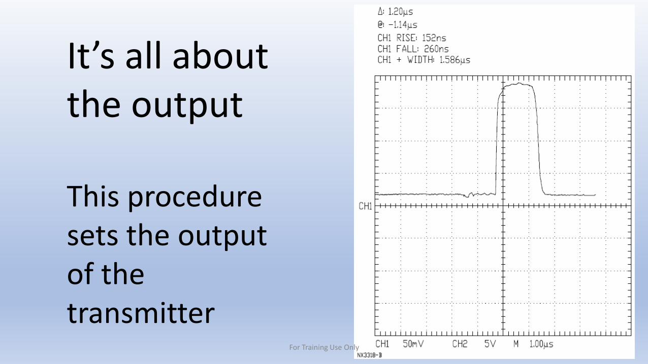
It’s all about the output
This procedure sets the output of the transmitter
For Training Use Only
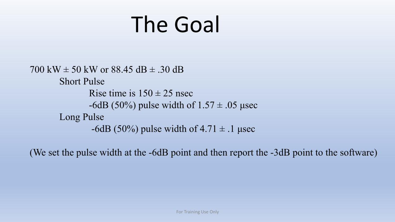
The Goal
700 kW ± 50 kW or 88.45 dB ± .30 dBShort Pulse
Rise time is 150 ± 25 nsec-6dB (50%) pulse width of 1.57 ± .05 μsec
Long Pulse-6dB (50%) pulse width of 4.71 ± .1 μsec
(We set the pulse width at the -6dB point and then report the -3dB point to the software)
For Training Use Only
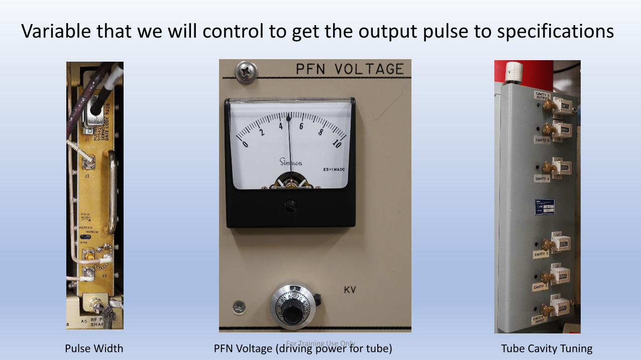
Pulse Width PFN Voltage (driving power for tube) Tube Cavity Tuning
Variable that we will control to get the output pulse to specifications
For Training Use Only
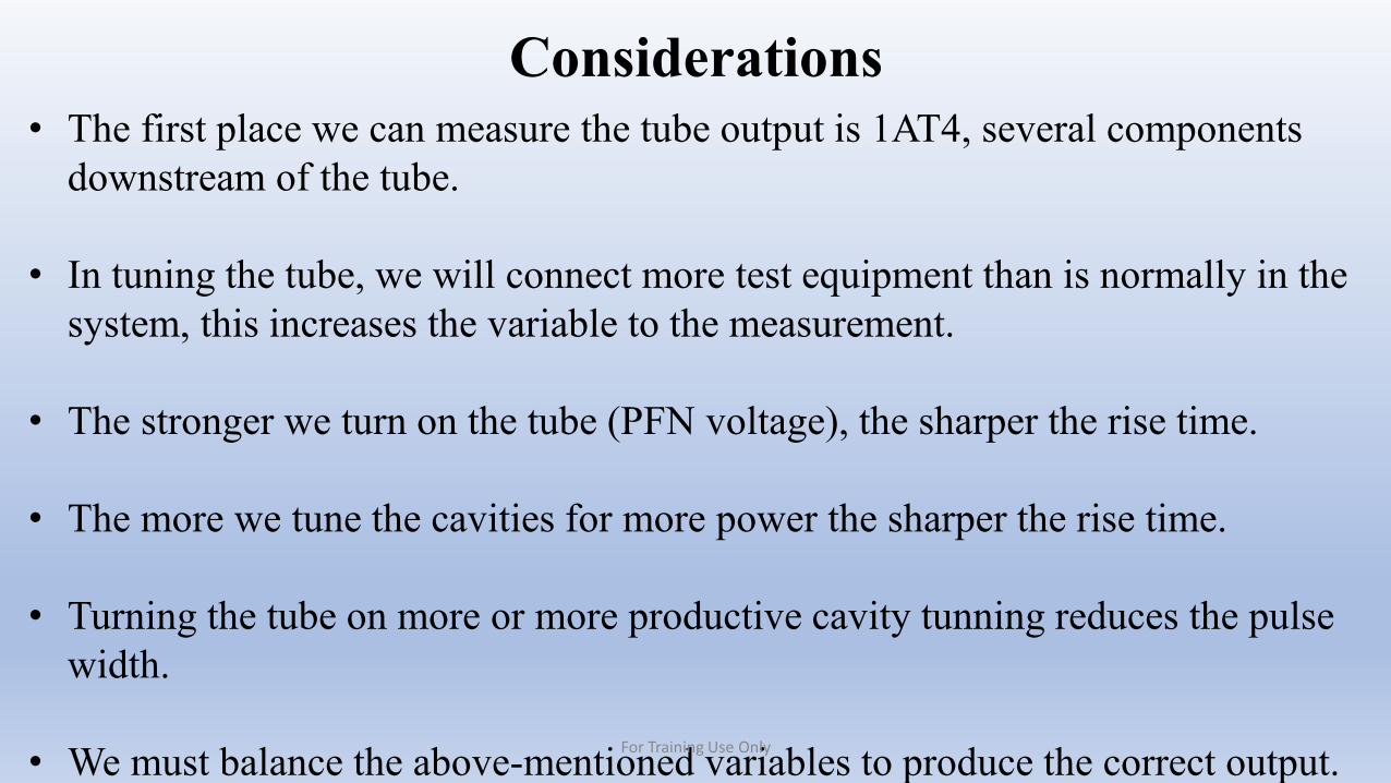
Considerations• The first place we can measure the tube output is 1AT4, several components
downstream of the tube.
• In tuning the tube, we will connect more test equipment than is normally in the system, this increases the variable to the measurement.
• The stronger we turn on the tube (PFN voltage), the sharper the rise time.
• The more we tune the cavities for more power the sharper the rise time.
• Turning the tube on more or more productive cavity tunning reduces the pulse width.
• We must balance the above-mentioned variables to produce the correct output.For Training Use Only
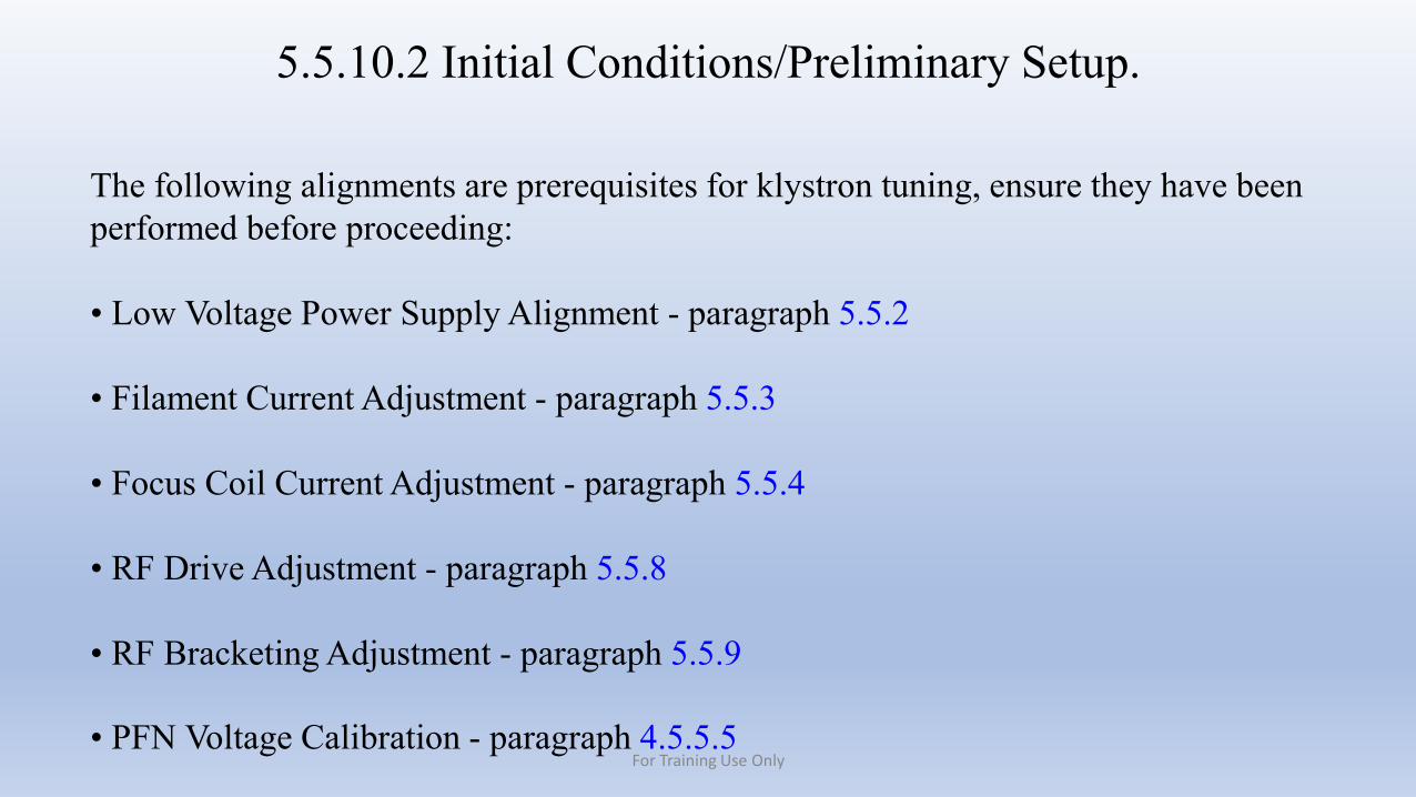
5.5.10.2 Initial Conditions/Preliminary Setup.
The following alignments are prerequisites for klystron tuning, ensure they have been performed before proceeding:
• Low Voltage Power Supply Alignment - paragraph 5.5.2
• Filament Current Adjustment - paragraph 5.5.3
• Focus Coil Current Adjustment - paragraph 5.5.4
• RF Drive Adjustment - paragraph 5.5.8
• RF Bracketing Adjustment - paragraph 5.5.9
• PFN Voltage Calibration - paragraph 4.5.5.5For Training Use Only

NOTEIf the Klystron was replaced, skip step 1 because the system is already in local control and the transmitter is powered down.
1. Gain control and place system in standby by performing the procedures in paragraph 3.4.1.2, steps 1 and 2.
2. Calibrate power meter and Power Sensor HP8481H per paragraph 3.4.4.
3. Remove the center bay transmitter cabinet door.
We should already be here
For Training Use Only
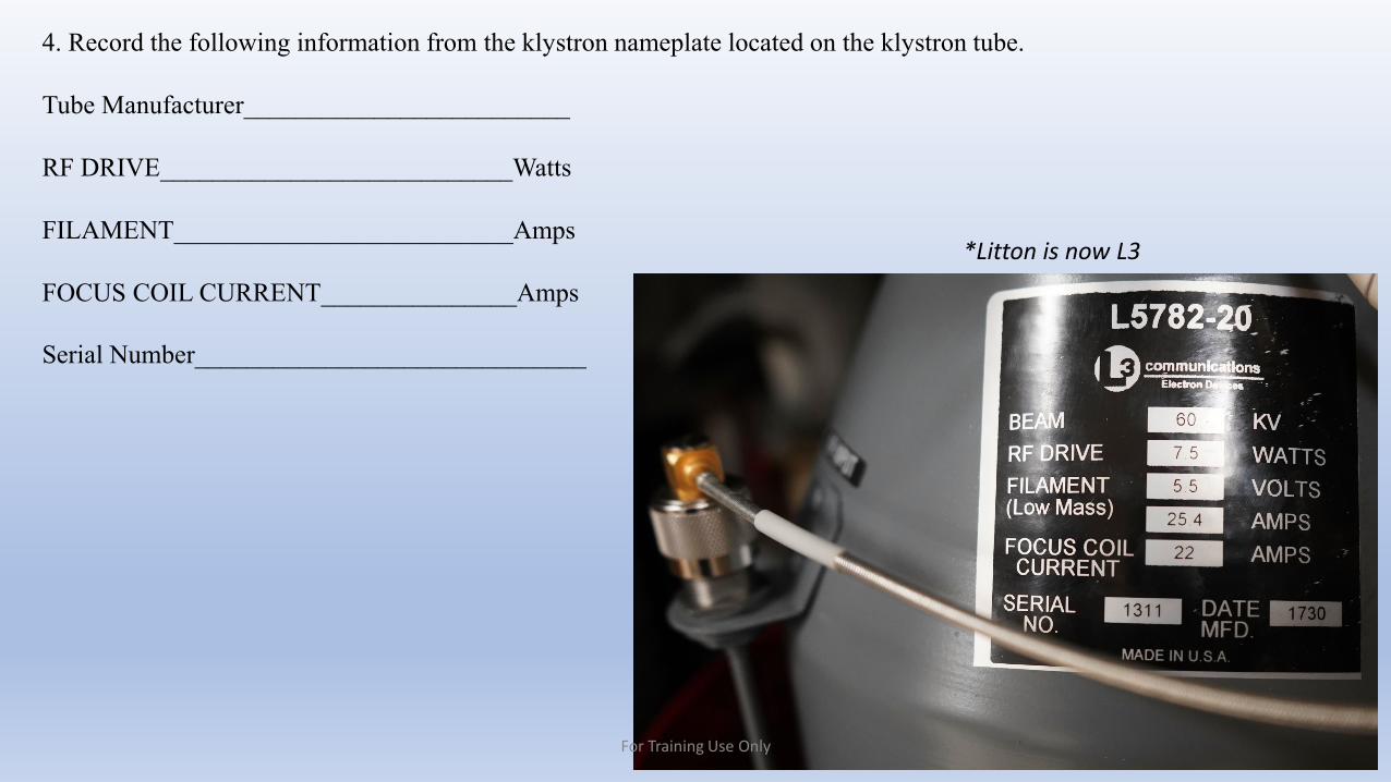
4. Record the following information from the klystron nameplate located on the klystron tube.
Tube Manufacturer_________________________
RF DRIVE___________________________Watts
FILAMENT__________________________Amps
FOCUS COIL CURRENT_______________Amps
Serial Number______________________________
Place Nameplate image here
*Litton is now L3
For Training Use Only
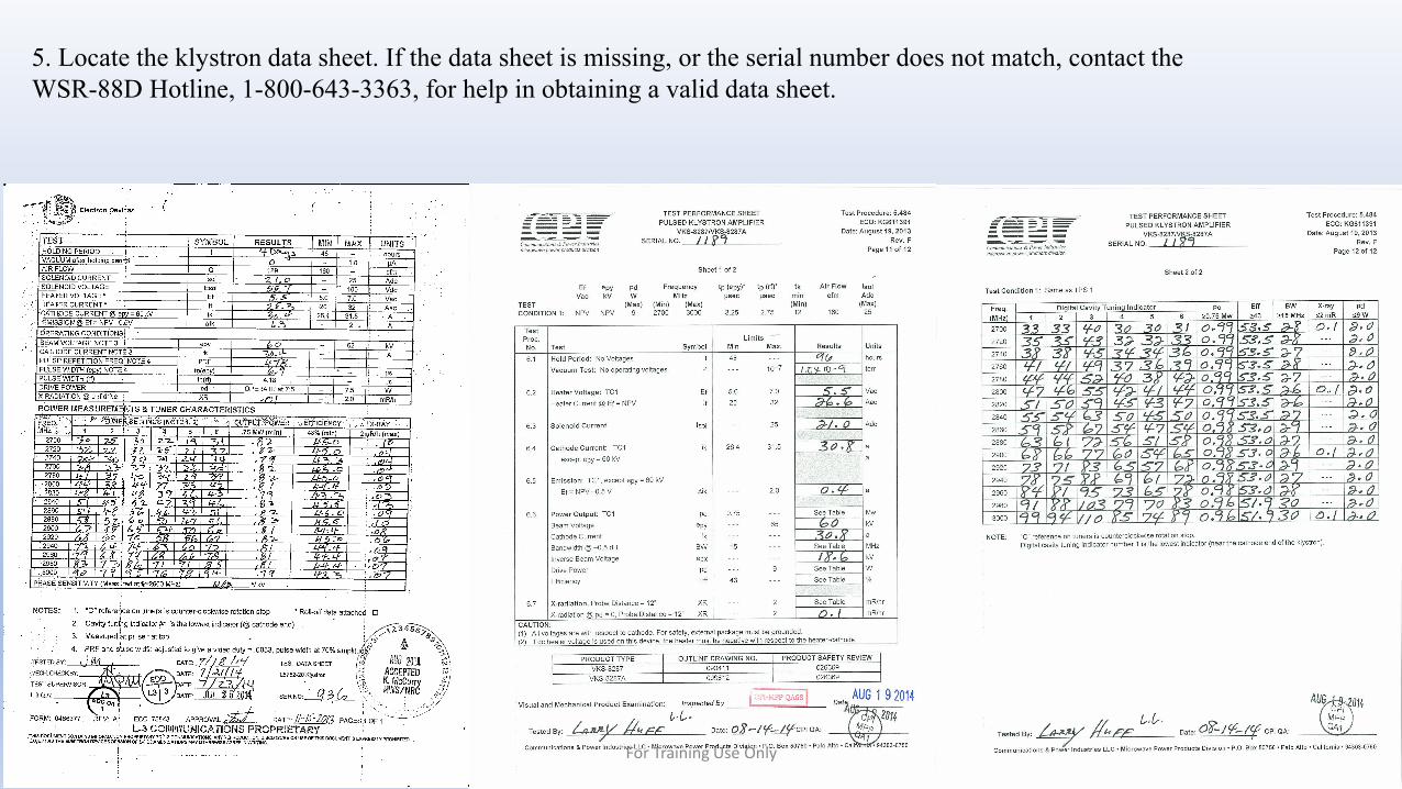
5. Locate the klystron data sheet. If the data sheet is missing, or the serial number does not match, contact the WSR-88D Hotline, 1-800-643-3363, for help in obtaining a valid data sheet.
For Training Use Only
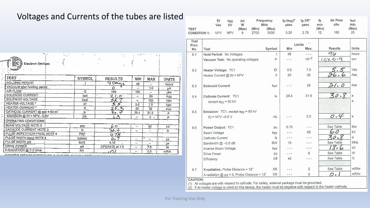
Voltages and Currents of the tubes are listed
For Training Use Only
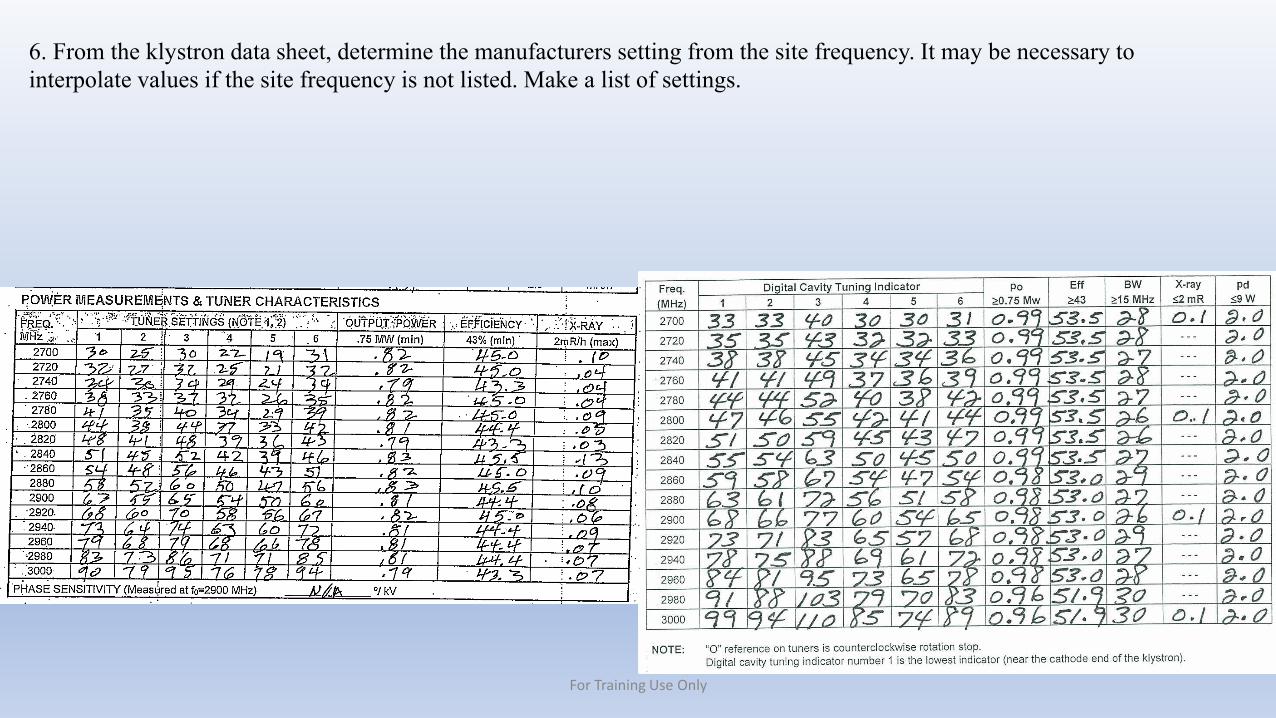
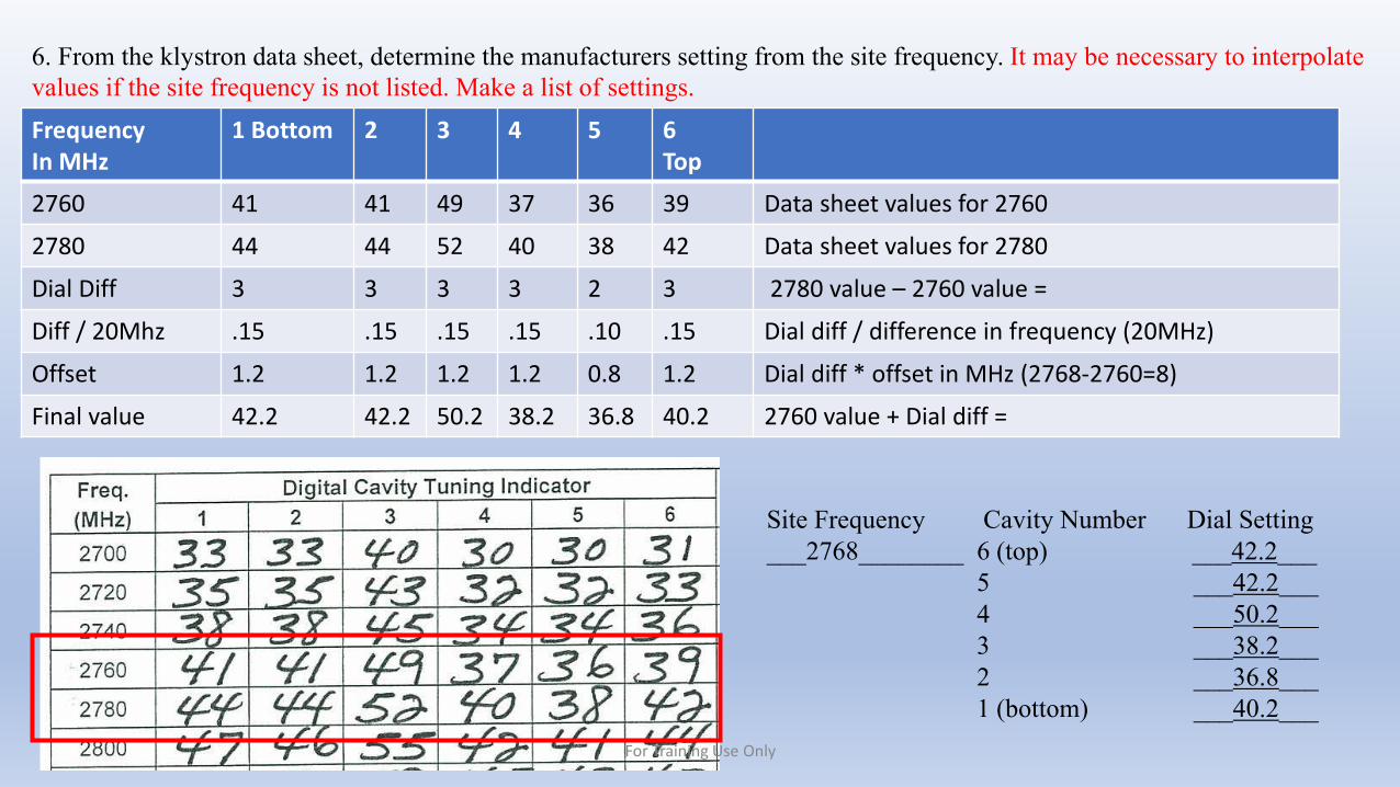
6. From the klystron data sheet, determine the manufacturers setting from the site frequency. It may be necessary to interpolate values if the site frequency is not listed. Make a list of settings.
For Training Use Only

Site Frequency Cavity Number Dial Setting__2800________ 6 (top) ___44_____
5 ___41_____4 ___42_____3 ___55_____2 ___46_____1 (bottom) ___47_____
6. From the klystron data sheet, determine the manufacturers setting from the site frequency. It may be necessary to interpolate values if the site frequency is not listed. Make a list of settings.
Site Frequency Cavity Number Dial Setting____________ 6 (top) __________
5 __________4 __________3 __________2 __________1 (bottom) __________
For Training Use Only
6. From the klystron data sheet, determine the manufacturers setting from the site frequency. It may be necessary to interpolate values if the site frequency is not listed. Make a list of settings.
Site Frequency Cavity Number Dial Setting___2768________ 6 (top) ___42.2___
5 ___42.2___4 ___50.2___3 ___38.2___2 ___36.8___1 (bottom) ___40.2___
FrequencyIn MHz
1 Bottom 2 3 4 5 6 Top
2760 41 41 49 37 36 39 Data sheet values for 2760
2780 44 44 52 40 38 42 Data sheet values for 2780
Dial Diff 3 3 3 3 2 3 2780 value – 2760 value =
Diff / 20Mhz .15 .15 .15 .15 .10 .15 Dial diff / difference in frequency (20MHz)
Offset 1.2 1.2 1.2 1.2 0.8 1.2 Dial diff * offset in MHz (2768-2760=8)
Final value 42.2 42.2 50.2 38.2 36.8 40.2 2760 value + Dial diff =
For Training Use Only
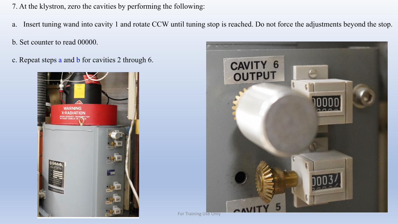
7. At the klystron, zero the cavities by performing the following:
a. Insert tuning wand into cavity 1 and rotate CCW until tuning stop is reached. Do not force the adjustments beyond the stop.
b. Set counter to read 00000.
c. Repeat steps a and b for cavities 2 through 6.
For Training Use Only
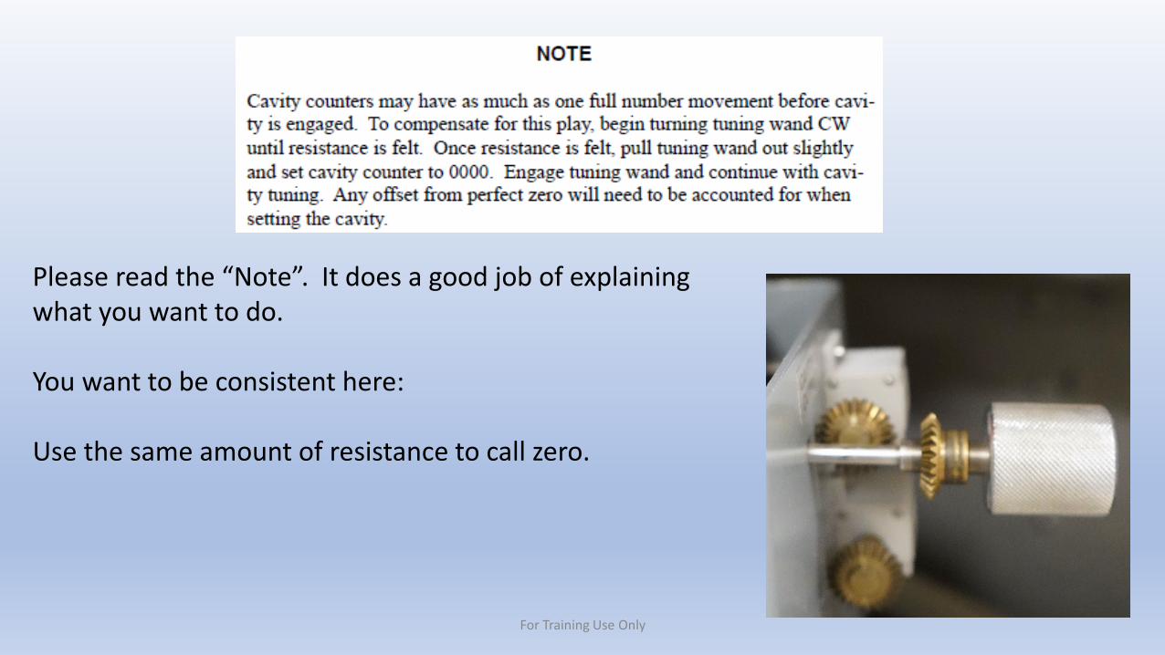
Please read the “Note”. It does a good job of explaining what you want to do.
You want to be consistent here:
Use the same amount of resistance to call zero.
For Training Use Only

8. Set the klystron cavities to the data sheet values interpolated for your site frequency from step 6.
Site Frequency Cavity Number Dial Setting____________ 6 (top) __________
5 __________4 __________3 __________2 __________1 (bottom) __________
9. Perform paragraph 5.5.10.2.1 only if the klystron tube has been replaced. If only tuning the transmitter, proceed to paragraph 5.5.10.3.
For Training Use Only
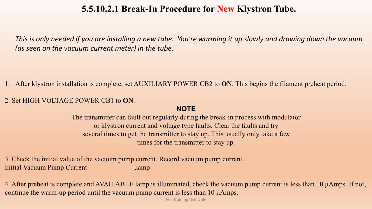
5.5.10.2.1 Break-In Procedure for New Klystron Tube.
1. After klystron installation is complete, set AUXILIARY POWER CB2 to ON. This begins the filament preheat period.
2. Set HIGH VOLTAGE POWER CB1 to ON.NOTE
The transmitter can fault out regularly during the break-in process with modulatoror klystron current and voltage type faults. Clear the faults and try
several times to get the transmitter to stay up. This usually only take a fewtimes for the transmitter to stay up.
3. Check the initial value of the vacuum pump current. Record vacuum pump current.Initial Vacuum Pump Current _____________μamp
4. After preheat is complete and AVAILABLE lamp is illuminated, check the vacuum pump current is less than 10 μAmps. If not, continue the warm-up period until the vacuum pump current is less than 10 μAmps.
This is only needed if you are installing a new tube. You're warming it up slowly and drawing down the vacuum (as seen on the vacuum current meter) in the tube.
For Training Use Only
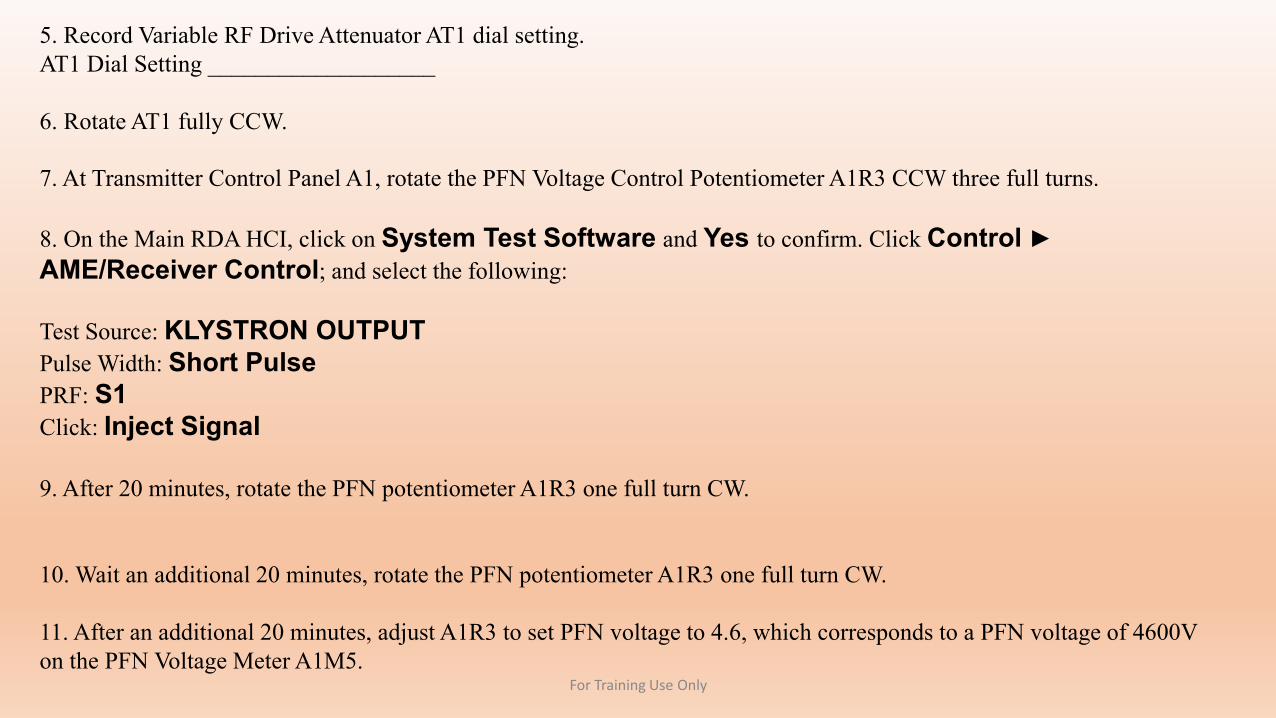
5. Record Variable RF Drive Attenuator AT1 dial setting.AT1 Dial Setting ___________________
6. Rotate AT1 fully CCW.
7. At Transmitter Control Panel A1, rotate the PFN Voltage Control Potentiometer A1R3 CCW three full turns.
8. On the Main RDA HCI, click on System Test Software and Yes to confirm. Click Control ►AME/Receiver Control; and select the following:
Test Source: KLYSTRON OUTPUTPulse Width: Short PulsePRF: S1Click: Inject Signal
9. After 20 minutes, rotate the PFN potentiometer A1R3 one full turn CW.
10. Wait an additional 20 minutes, rotate the PFN potentiometer A1R3 one full turn CW.
11. After an additional 20 minutes, adjust A1R3 to set PFN voltage to 4.6, which corresponds to a PFN voltage of 4600V on the PFN Voltage Meter A1M5.
For Training Use Only
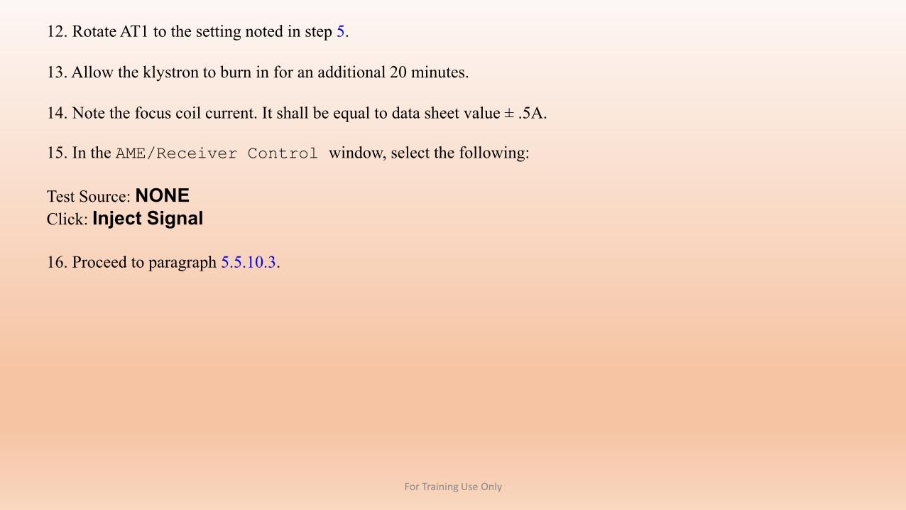
12. Rotate AT1 to the setting noted in step 5.
13. Allow the klystron to burn in for an additional 20 minutes.
14. Note the focus coil current. It shall be equal to data sheet value ± .5A.
15. In the AME/Receiver Control window, select the following:
Test Source: NONEClick: Inject Signal
16. Proceed to paragraph 5.5.10.3.
For Training Use Only
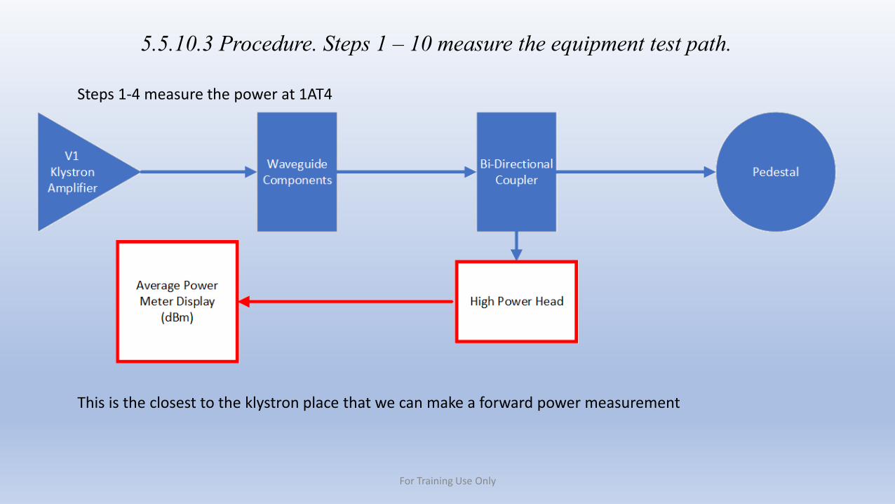
5.5.10.3 Procedure. Steps 1 – 10 measure the equipment test path.
Steps 1-4 measure the power at 1AT4
This is the closest to the klystron place that we can make a forward power measurement
For Training Use Only
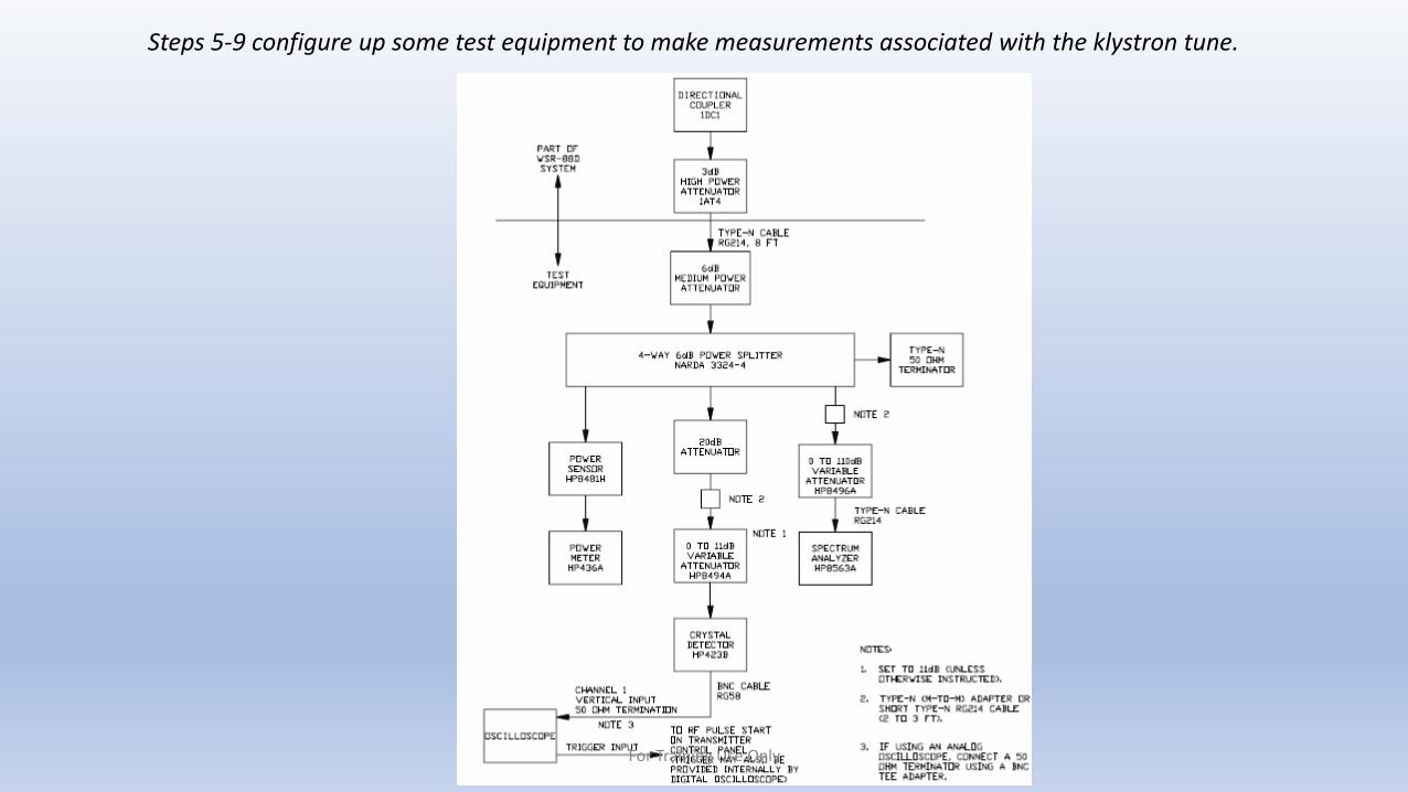
Steps 5-9 configure up some test equipment to make measurements associated with the klystron tune.
For Training Use Only
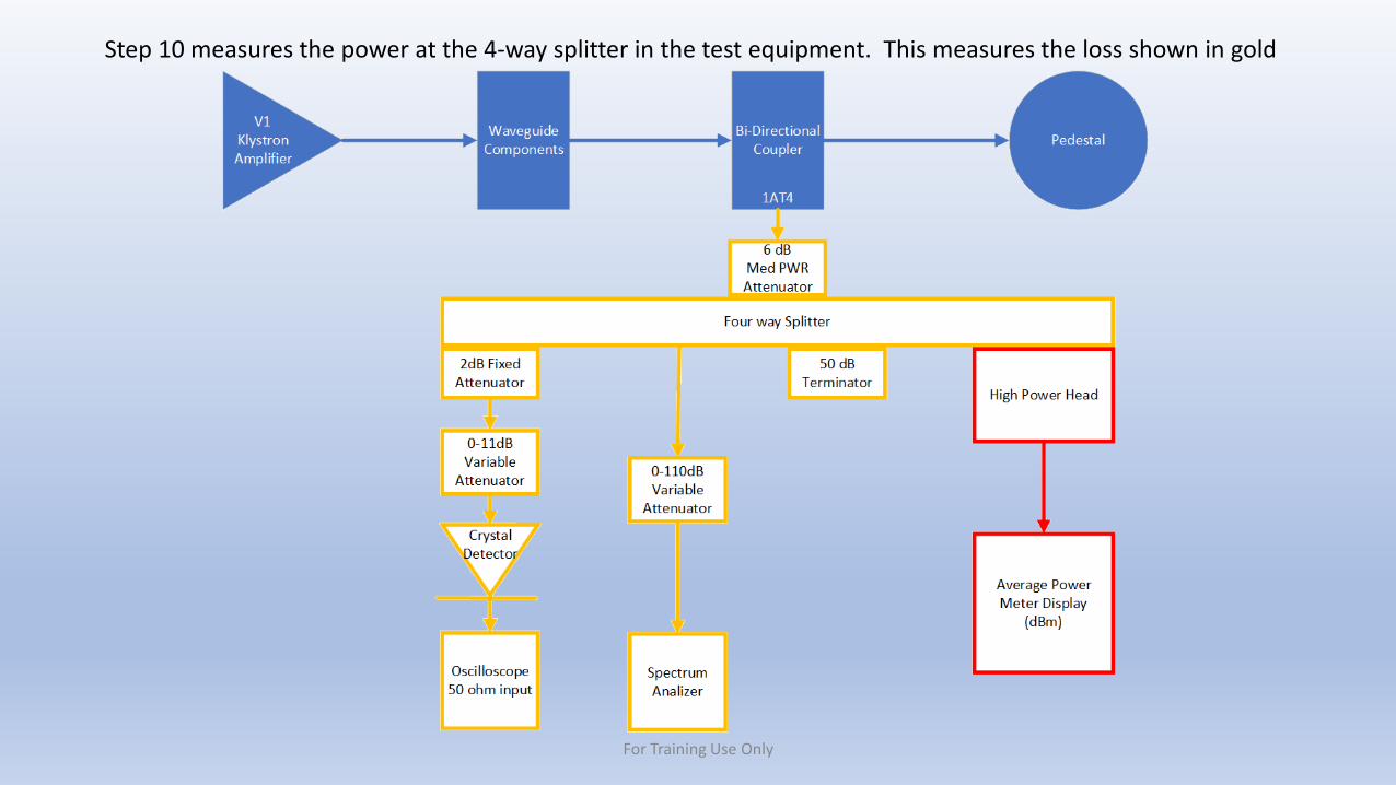
Step 10 measures the power at the 4-way splitter in the test equipment. This measures the loss shown in gold
For Training Use Only
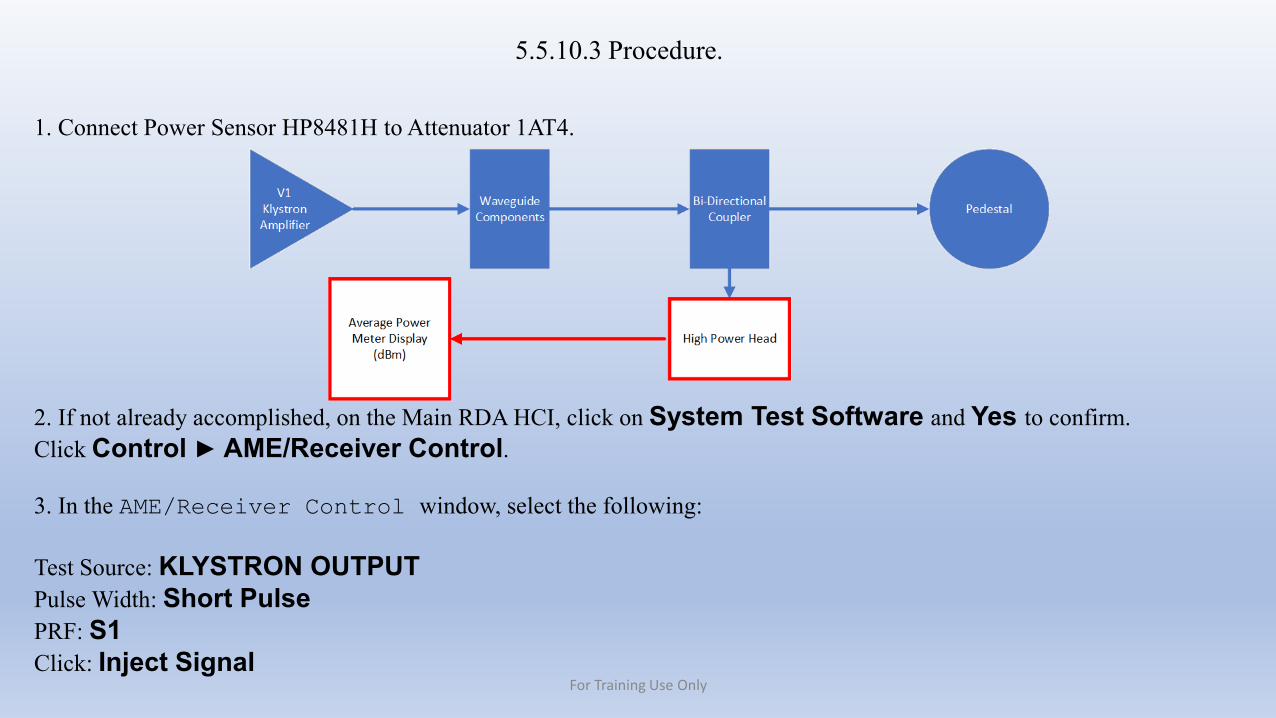
5.5.10.3 Procedure.
1. Connect Power Sensor HP8481H to Attenuator 1AT4.
2. If not already accomplished, on the Main RDA HCI, click on System Test Software and Yes to confirm. Click Control ► AME/Receiver Control.
3. In the AME/Receiver Control window, select the following:
Test Source: KLYSTRON OUTPUTPulse Width: Short PulsePRF: S1Click: Inject Signal
For Training Use Only
4. At Transmitter Control Panel A1, adjust A1R3 until the PFN VOLTAGE Meter A1M5 reads 4.6 which corresponds to a PFN voltage of 4600V.
NWSTC Note: Make sure you set the 4600V BEFORE you make the measurement below.
Allow power meter to stabilize, and record power meter reading:Power @1AT4_________________________dBm
NWSTC Note:This is part of the math in step 20.
This measurement is compared to the measurement in step 10 to measure the test equipment loss. This power is assumed to not change until after step 10. If this power changes before step 10 is made, then the math in step 20 is off by that amount.
For Training Use Only
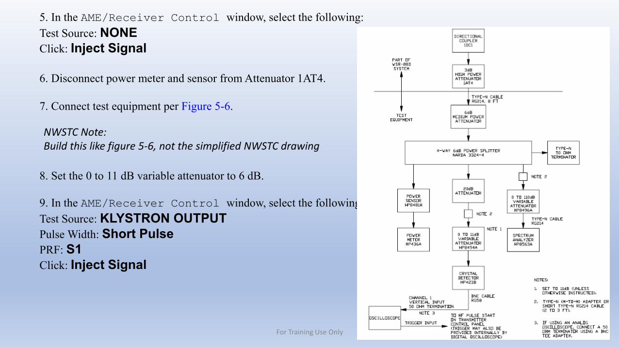
5. In the AME/Receiver Control window, select the following:Test Source: NONEClick: Inject Signal
6. Disconnect power meter and sensor from Attenuator 1AT4.
7. Connect test equipment per Figure 5-6.
8. Set the 0 to 11 dB variable attenuator to 6 dB.
9. In the AME/Receiver Control window, select the following:Test Source: KLYSTRON OUTPUTPulse Width: Short PulsePRF: S1Click: Inject Signal
NWSTC Note:Build this like figure 5-6, not the simplified NWSTC drawing
For Training Use Only
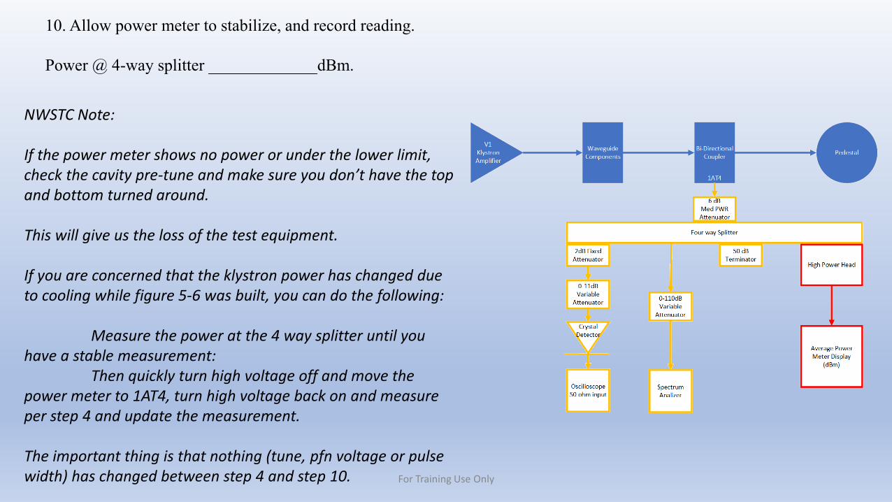
10. Allow power meter to stabilize, and record reading.
Power @ 4-way splitter _____________dBm.
NWSTC Note:
If the power meter shows no power or under the lower limit, check the cavity pre-tune and make sure you don’t have the top and bottom turned around.
This will give us the loss of the test equipment.
If you are concerned that the klystron power has changed due to cooling while figure 5-6 was built, you can do the following:
Measure the power at the 4 way splitter until you have a stable measurement:
Then quickly turn high voltage off and move the power meter to 1AT4, turn high voltage back on and measure per step 4 and update the measurement.
The important thing is that nothing (tune, pfn voltage or pulse width) has changed between step 4 and step 10. For Training Use Only
11. Using the klystron tuning tool, adjust klystron cavities 1 and 6 for peak power reading as observed on the power meter.12. Set up the oscilloscope to measure the output detected pulse by performing the following:
NOTEOscilloscope procedures may vary according to model being used.
a. Trigger the oscilloscope by performing the following. Ensure the oscilloscope is terminated at 50 Ω (internally or externally).
For digital oscilloscopes: Trigger to channel 1, positive slope.For analog oscilloscopes: Trigger to RF Pulse Start on the Transmitter Control Panel A1.
b. Adjust V/division for best displayed pulse. This setting is usually between 10 and50 mV/cm.
c. Set the time/division to 0.5 μsec/div (500 nsec).
NOTEIf the displayed pulse is a negative going pulse, measure fall time instead of rise time.
For Training Use Only
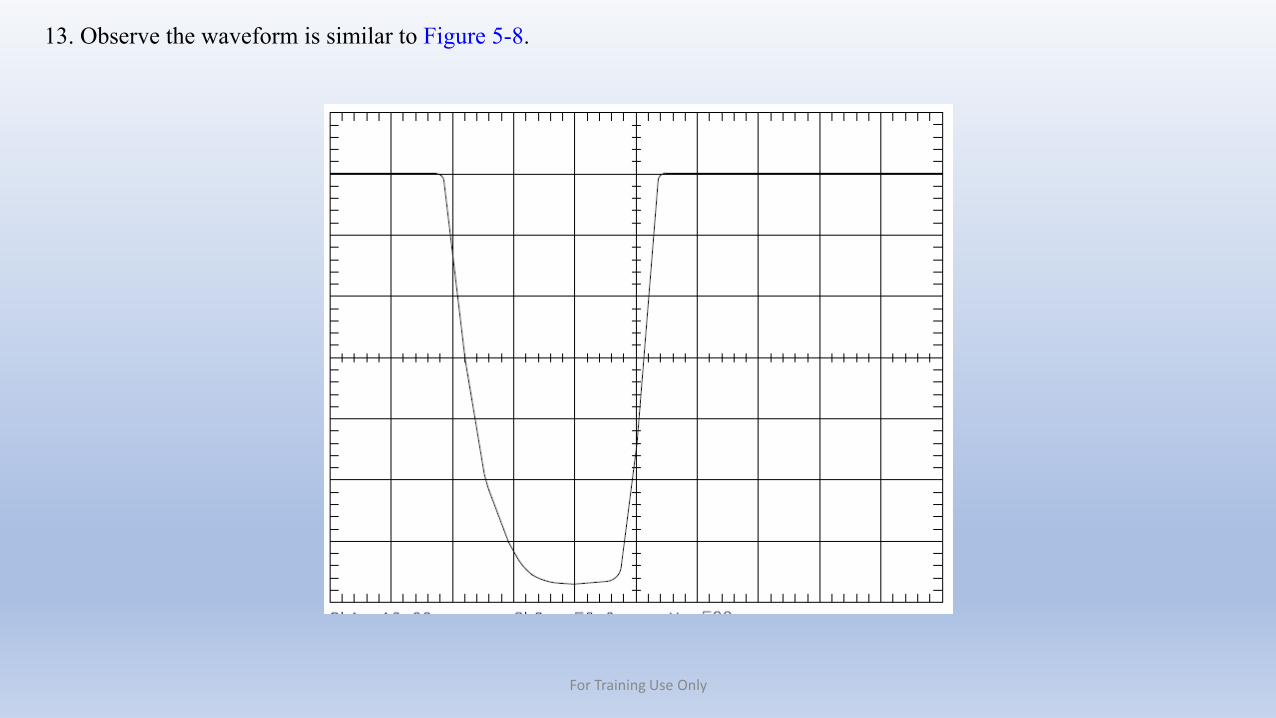
13. Observe the waveform is similar to Figure 5-8.
For Training Use Only
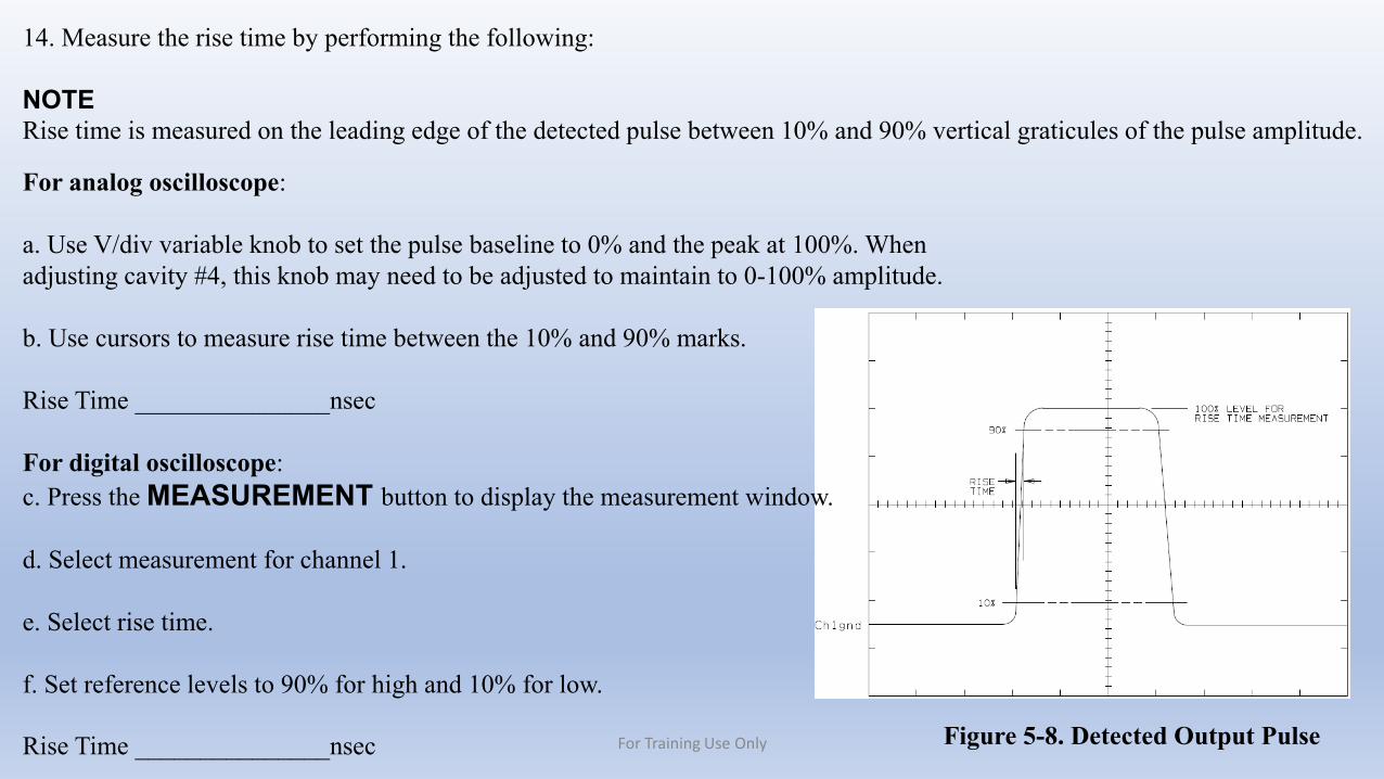
14. Measure the rise time by performing the following:
NOTERise time is measured on the leading edge of the detected pulse between 10% and 90% vertical graticules of the pulse amplitude.
Figure 5-8. Detected Output Pulse
For analog oscilloscope:
a. Use V/div variable knob to set the pulse baseline to 0% and the peak at 100%. Whenadjusting cavity #4, this knob may need to be adjusted to maintain to 0-100% amplitude.
b. Use cursors to measure rise time between the 10% and 90% marks.
Rise Time _______________nsec
For digital oscilloscope:c. Press the MEASUREMENT button to display the measurement window.
d. Select measurement for channel 1.
e. Select rise time.
f. Set reference levels to 90% for high and 10% for low.
Rise Time _______________nsec For Training Use Only
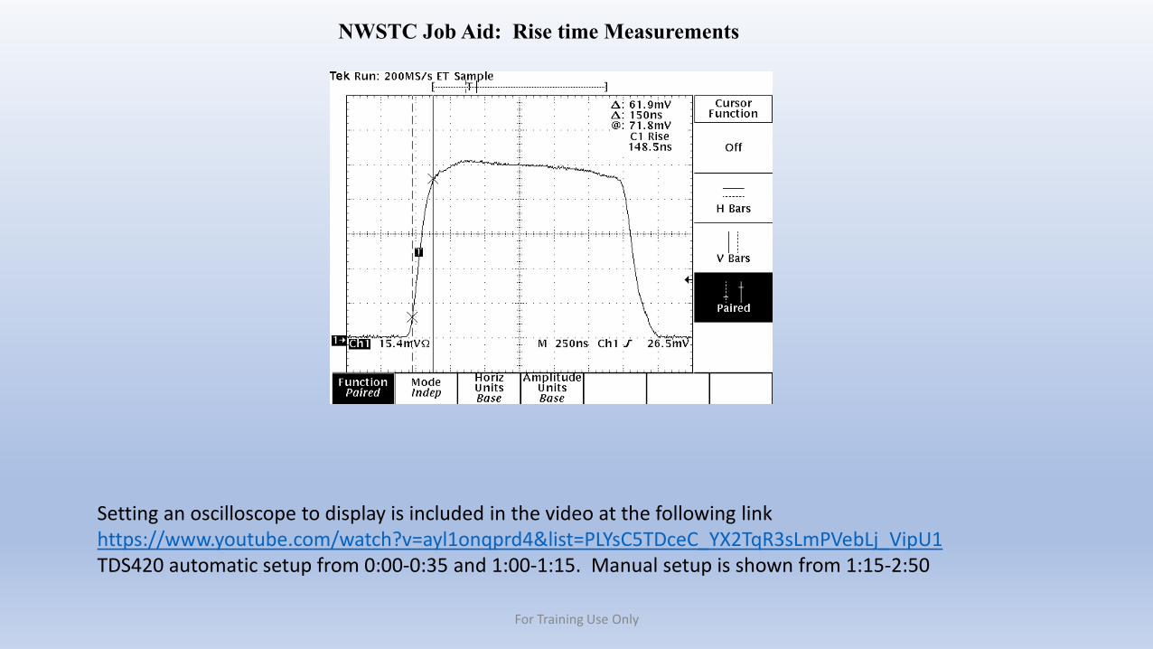
NWSTC Job Aid: Rise time Measurements
Setting an oscilloscope to display is included in the video at the following linkhttps://www.youtube.com/watch?v=ayl1onqprd4&list=PLYsC5TDceC_YX2TqR3sLmPVebLj_VipU1TDS420 automatic setup from 0:00-0:35 and 1:00-1:15. Manual setup is shown from 1:15-2:50
For Training Use Only
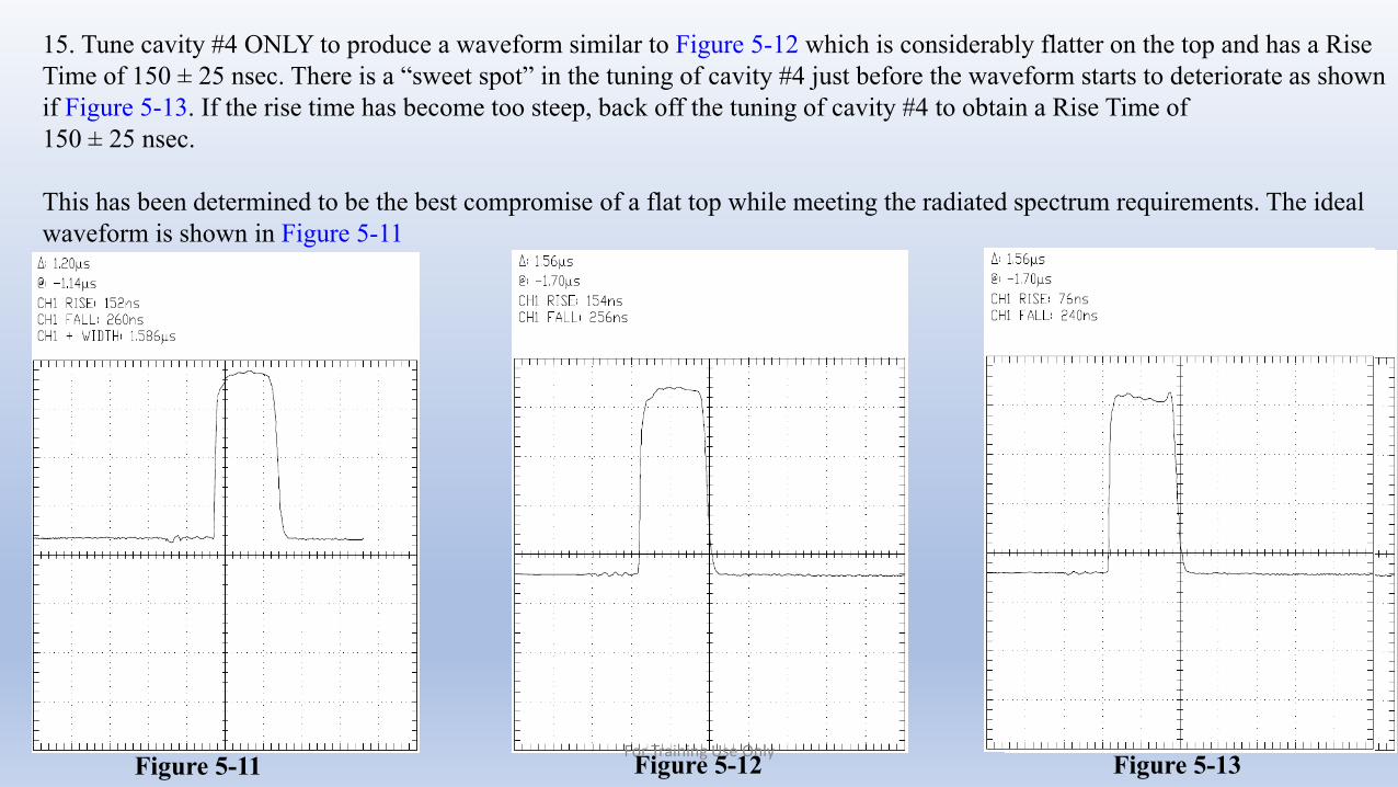
15. Tune cavity #4 ONLY to produce a waveform similar to Figure 5-12 which is considerably flatter on the top and has a Rise Time of 150 ± 25 nsec. There is a “sweet spot” in the tuning of cavity #4 just before the waveform starts to deteriorate as shown if Figure 5-13. If the rise time has become too steep, back off the tuning of cavity #4 to obtain a Rise Time of150 ± 25 nsec.
This has been determined to be the best compromise of a flat top while meeting the radiated spectrum requirements. The ideal waveform is shown in Figure 5-11
Figure 5-11 Figure 5-12 Figure 5-13For Training Use Only

NWSTC Job Aid: Cavity 4 adjustment
Adjustment of cavity 4 is included in the video at the following link between 0:35 and 1:00https://www.youtube.com/watch?v=ayl1onqprd4&list=PLYsC5TDceC_YX2TqR3sLmPVebLj_VipU1
For Training Use OnlyA link will also be found at: https://training.weather.gov/nwstc/NEXRAD/transmitter/index.html
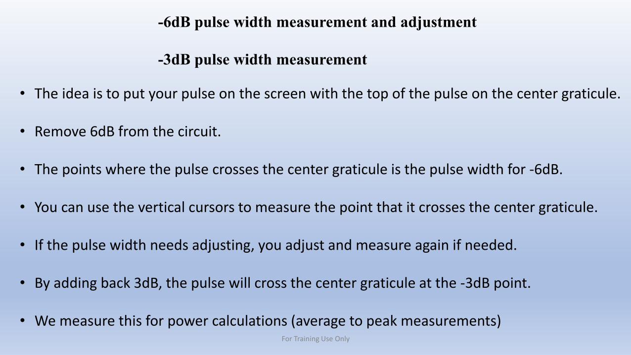
-6dB pulse width measurement and adjustment
-3dB pulse width measurement
• The idea is to put your pulse on the screen with the top of the pulse on the center graticule.
• Remove 6dB from the circuit.
• The points where the pulse crosses the center graticule is the pulse width for -6dB.
• You can use the vertical cursors to measure the point that it crosses the center graticule.
• If the pulse width needs adjusting, you adjust and measure again if needed.
• By adding back 3dB, the pulse will cross the center graticule at the -3dB point.
• We measure this for power calculations (average to peak measurements)For Training Use Only
-6dB pulse width measurement and adjustment and -3dB pulse width measurementContinued
See video link at https://training.weather.gov/nwstc/NEXRAD/transmitter/index.htmlFor Training Use Only
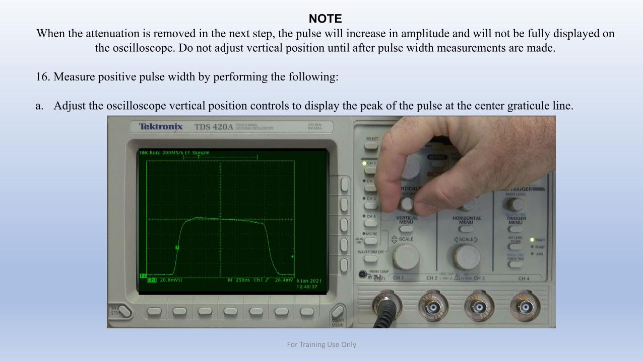
NOTEWhen the attenuation is removed in the next step, the pulse will increase in amplitude and will not be fully displayed on
the oscilloscope. Do not adjust vertical position until after pulse width measurements are made.
16. Measure positive pulse width by performing the following:
a. Adjust the oscilloscope vertical position controls to display the peak of the pulse at the center graticule line.
For Training Use Only
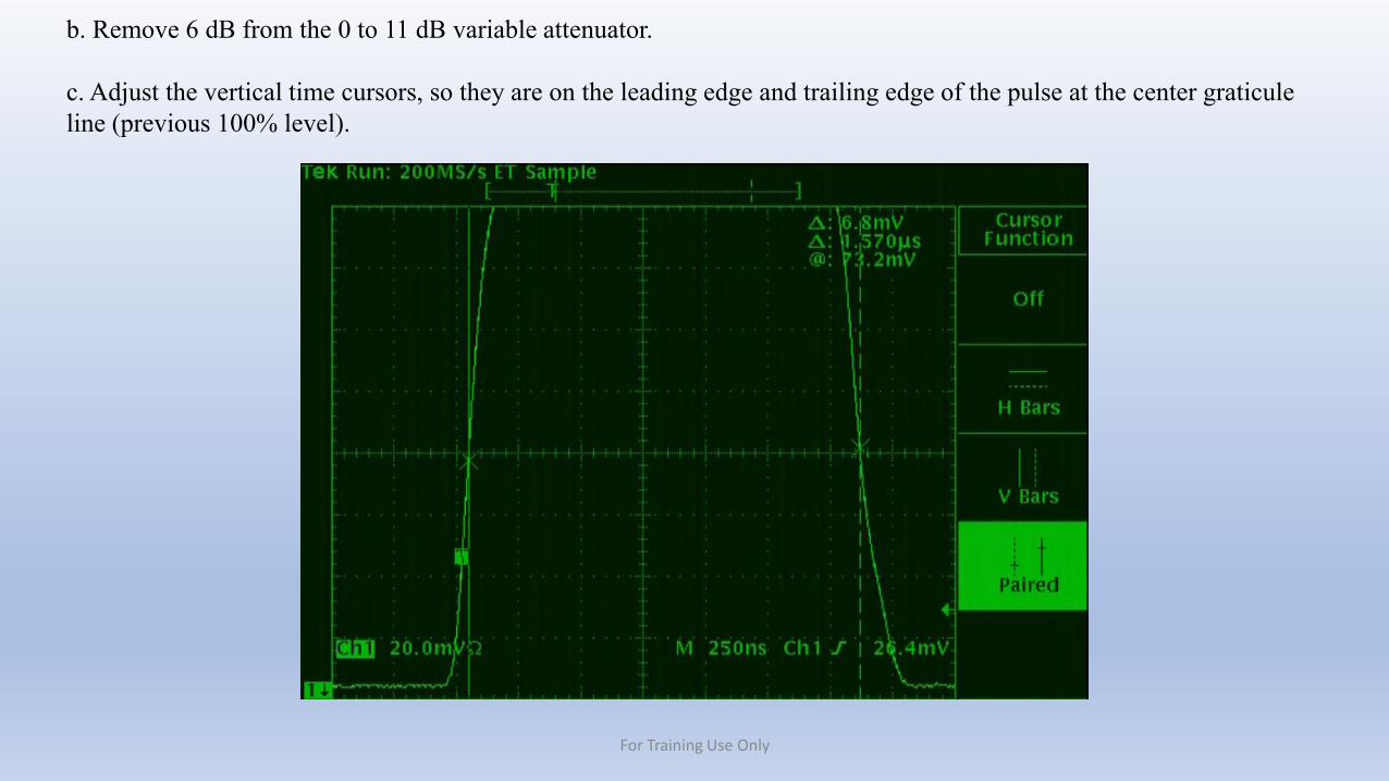
b. Remove 6 dB from the 0 to 11 dB variable attenuator.
c. Adjust the vertical time cursors, so they are on the leading edge and trailing edge of the pulse at the center graticule line (previous 100% level).
For Training Use Only
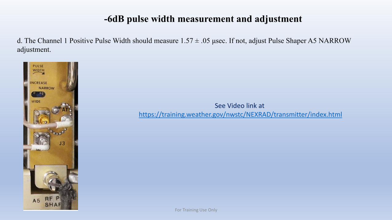
d. The Channel 1 Positive Pulse Width should measure 1.57 ± .05 μsec. If not, adjust Pulse Shaper A5 NARROW adjustment.
-6dB pulse width measurement and adjustment
See Video link at https://training.weather.gov/nwstc/NEXRAD/transmitter/index.html
For Training Use Only
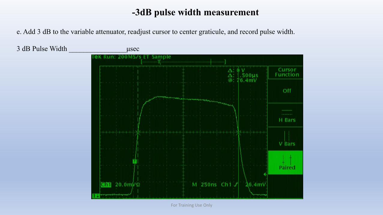
e. Add 3 dB to the variable attenuator, readjust cursor to center graticule, and record pulse width.
3 dB Pulse Width ________________μsec
-3dB pulse width measurement
For Training Use Only
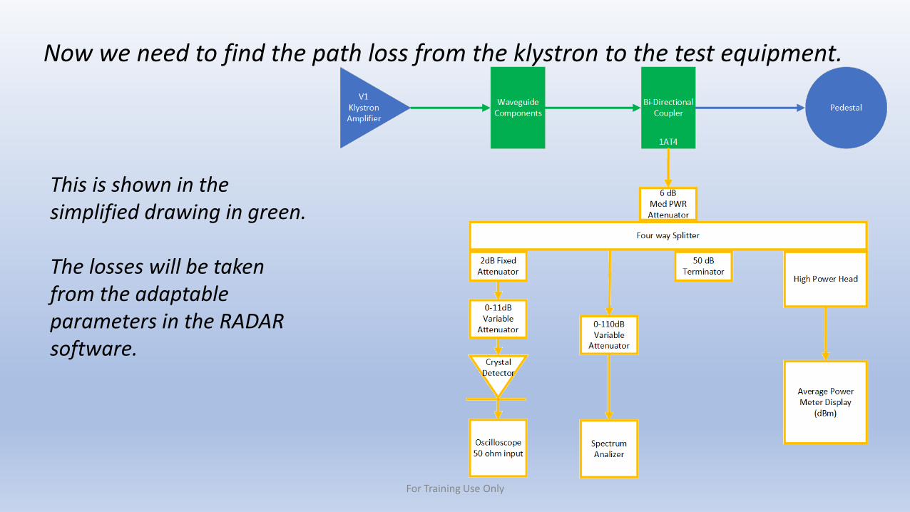
Now we need to find the path loss from the klystron to the test equipment.
This is shown in the simplified drawing in green.
The losses will be taken from the adaptable parameters in the RADAR software.
For Training Use Only
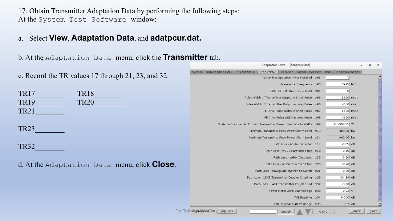
17. Obtain Transmitter Adaptation Data by performing the following steps:At the System Test Software window:
a. Select View, Adaptation Data, and adatpcur.dat.
b. At the Adaptation Data menu, click the Transmitter tab.
c. Record the TR values 17 through 21, 23, and 32.
TR17________ TR18________TR19________ TR20________TR21________
TR23________
TR32________
d. At the Adaptation Data menu, click Close.
Screenshot here
For Training Use Only
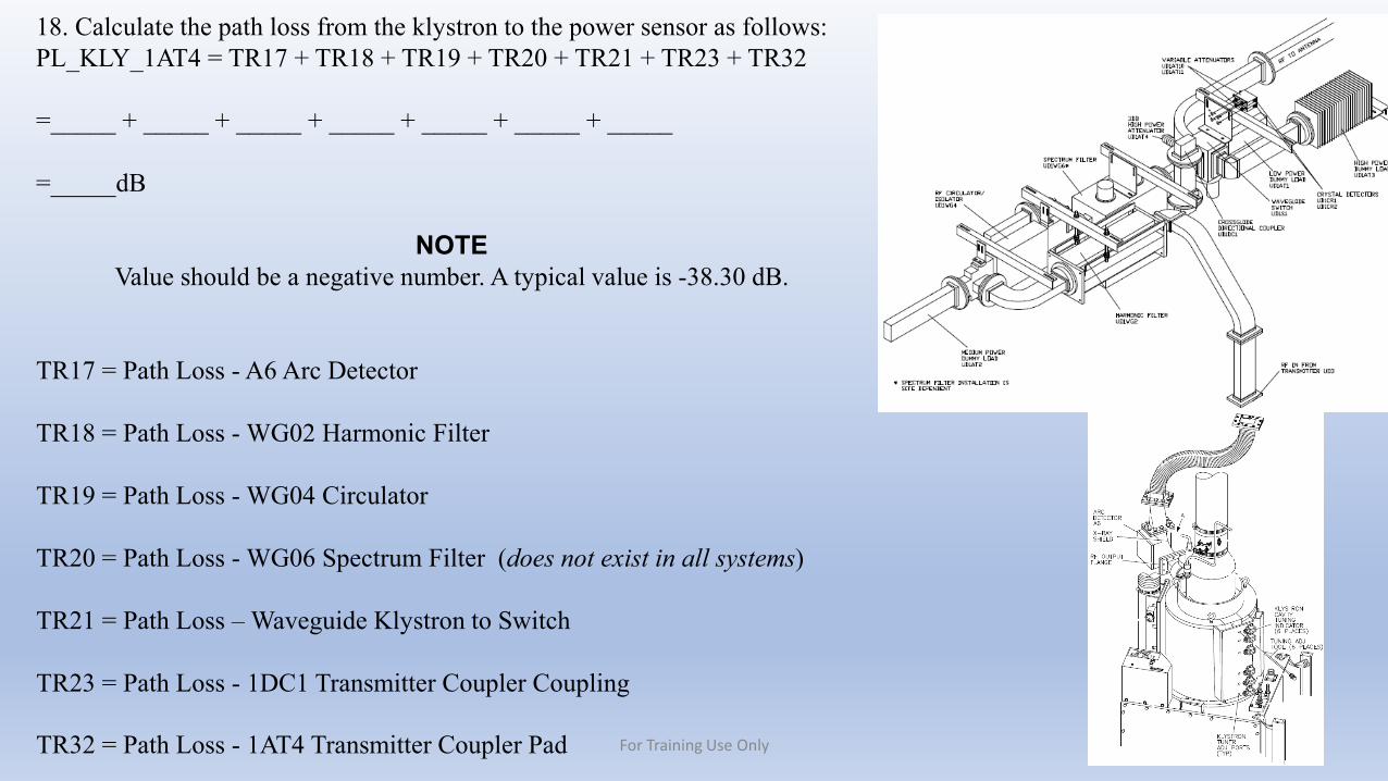
18. Calculate the path loss from the klystron to the power sensor as follows:PL_KLY_1AT4 = TR17 + TR18 + TR19 + TR20 + TR21 + TR23 + TR32
=_____ + _____ + _____ + _____ + _____ + _____ + _____
=_____dB
NOTEValue should be a negative number. A typical value is -38.30 dB.
TR17 = Path Loss - A6 Arc Detector
TR18 = Path Loss - WG02 Harmonic Filter
TR19 = Path Loss - WG04 Circulator
TR20 = Path Loss - WG06 Spectrum Filter (does not exist in all systems)
TR21 = Path Loss – Waveguide Klystron to Switch
TR23 = Path Loss - 1DC1 Transmitter Coupler Coupling
TR32 = Path Loss - 1AT4 Transmitter Coupler Pad For Training Use Only
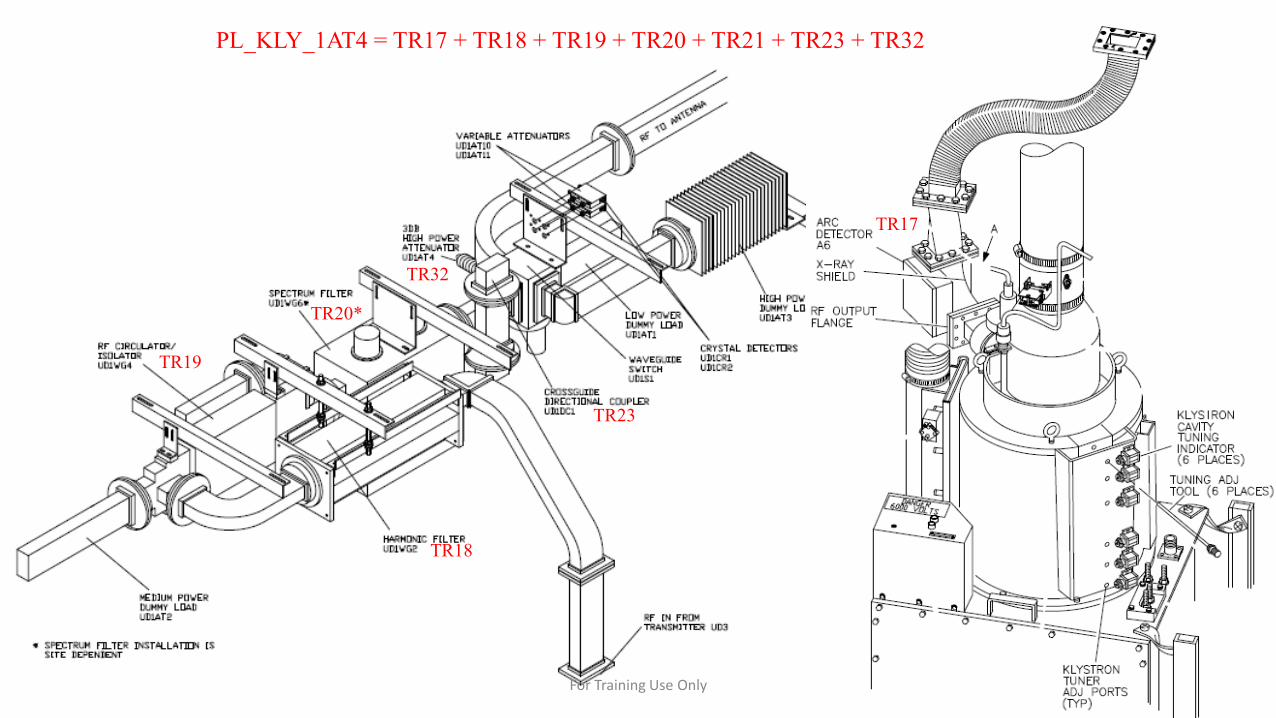
TR17
TR18
TR19
TR20*
TR23
TR32
PL_KLY_1AT4 = TR17 + TR18 + TR19 + TR20 + TR21 + TR23 + TR32
For Training Use Only
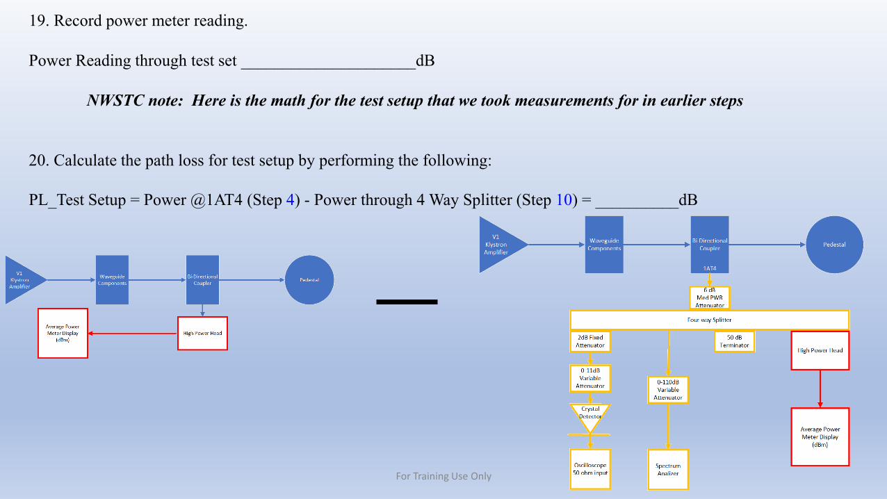
19. Record power meter reading.
Power Reading through test set _____________________dB
NWSTC note: Here is the math for the test setup that we took measurements for in earlier steps
20. Calculate the path loss for test setup by performing the following:
PL_Test Setup = Power @1AT4 (Step 4) - Power through 4 Way Splitter (Step 10) = __________dB
For Training Use Only
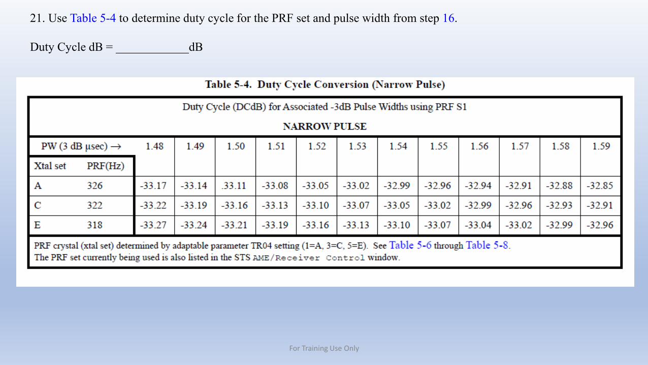
21. Use Table 5-4 to determine duty cycle for the PRF set and pulse width from step 16.
Duty Cycle dB = ____________dB
For Training Use Only
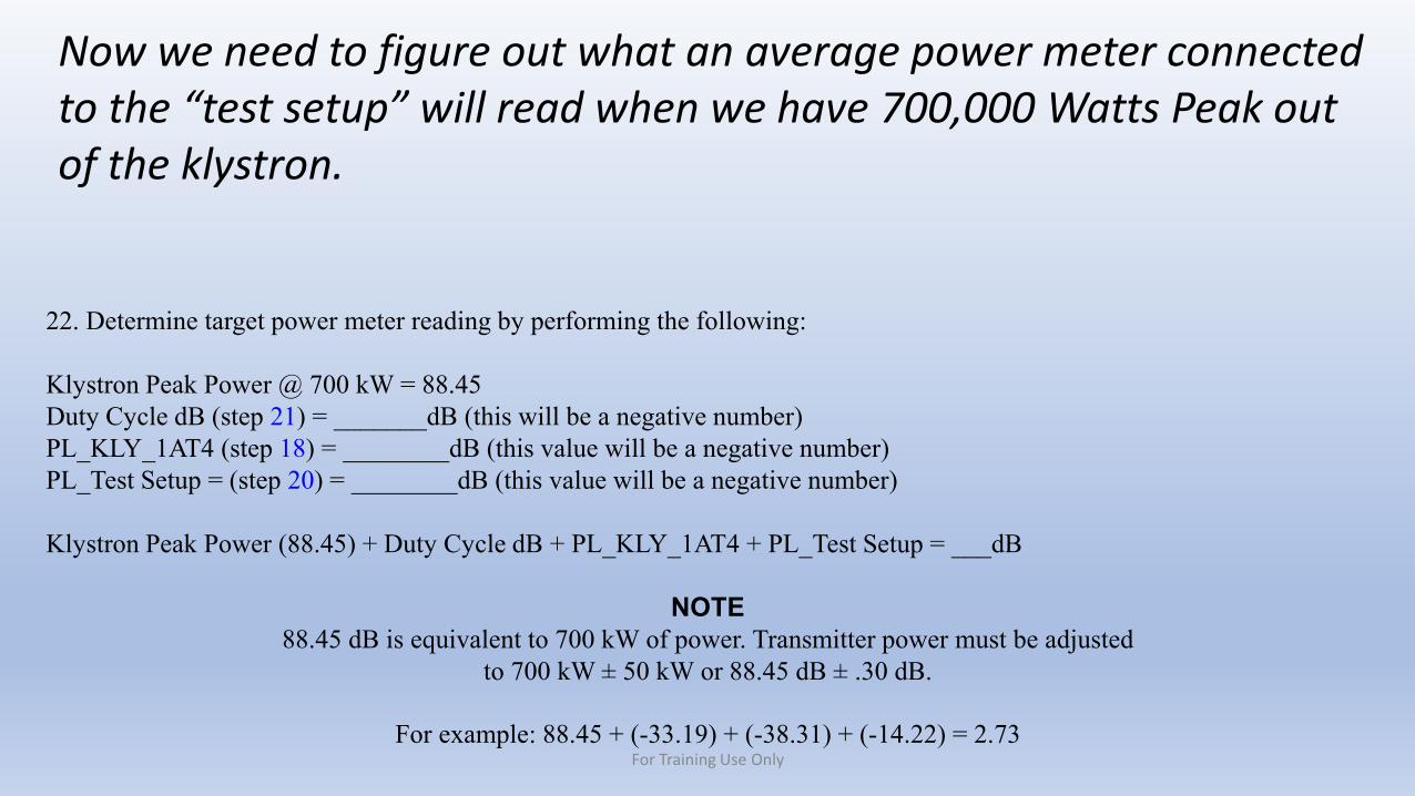
22. Determine target power meter reading by performing the following:
Klystron Peak Power @ 700 kW = 88.45Duty Cycle dB (step 21) = _______dB (this will be a negative number)PL_KLY_1AT4 (step 18) = ________dB (this value will be a negative number)PL_Test Setup = (step 20) = ________dB (this value will be a negative number)
Klystron Peak Power (88.45) + Duty Cycle dB + PL_KLY_1AT4 + PL_Test Setup = ___dB
NOTE88.45 dB is equivalent to 700 kW of power. Transmitter power must be adjusted
to 700 kW ± 50 kW or 88.45 dB ± .30 dB.
For example: 88.45 + (-33.19) + (-38.31) + (-14.22) = 2.73
Now we need to figure out what an average power meter connected to the “test setup” will read when we have 700,000 Watts Peak out of the klystron.
For Training Use Only
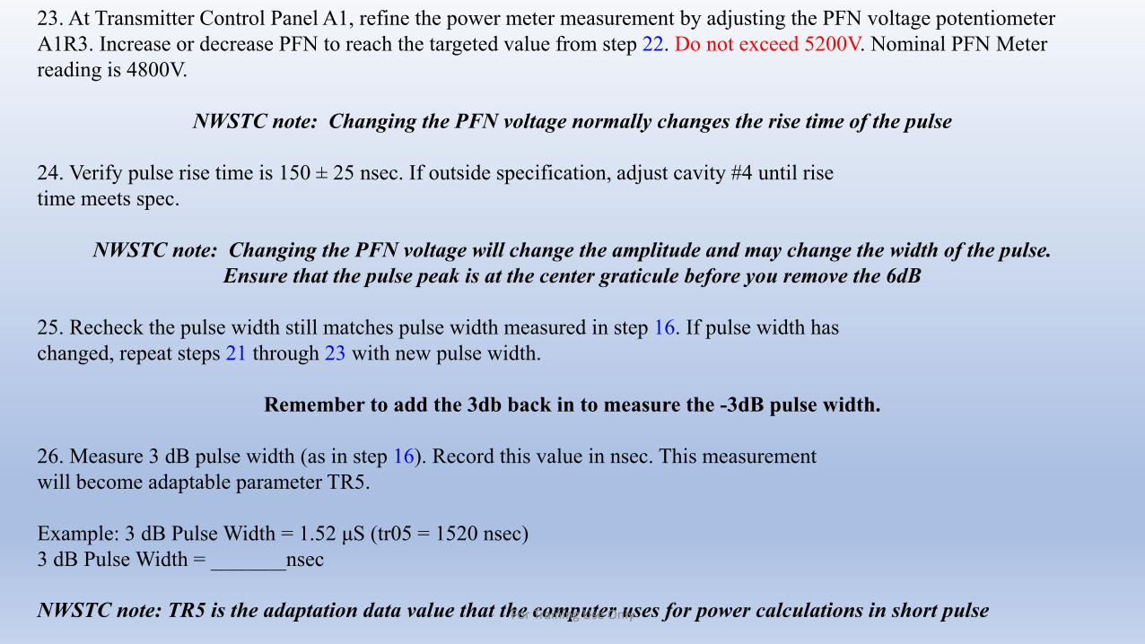
23. At Transmitter Control Panel A1, refine the power meter measurement by adjusting the PFN voltage potentiometer A1R3. Increase or decrease PFN to reach the targeted value from step 22. Do not exceed 5200V. Nominal PFN Meter reading is 4800V.
NWSTC note: Changing the PFN voltage normally changes the rise time of the pulse
24. Verify pulse rise time is 150 ± 25 nsec. If outside specification, adjust cavity #4 until risetime meets spec.
NWSTC note: Changing the PFN voltage will change the amplitude and may change the width of the pulse.Ensure that the pulse peak is at the center graticule before you remove the 6dB
25. Recheck the pulse width still matches pulse width measured in step 16. If pulse width haschanged, repeat steps 21 through 23 with new pulse width.
Remember to add the 3db back in to measure the -3dB pulse width.
26. Measure 3 dB pulse width (as in step 16). Record this value in nsec. This measurementwill become adaptable parameter TR5.
Example: 3 dB Pulse Width = 1.52 μS (tr05 = 1520 nsec)3 dB Pulse Width = _______nsec
NWSTC note: TR5 is the adaptation data value that the computer uses for power calculations in short pulseFor Training Use Only
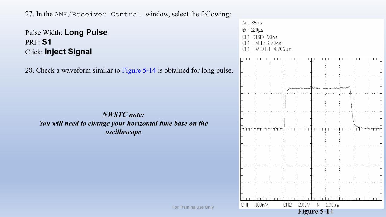
27. In the AME/Receiver Control window, select the following:
Pulse Width: Long PulsePRF: S1Click: Inject Signal
28. Check a waveform similar to Figure 5-14 is obtained for long pulse.
Figure 5-14
NWSTC note: You will need to change your horizontal time base on the
oscilloscope
For Training Use Only
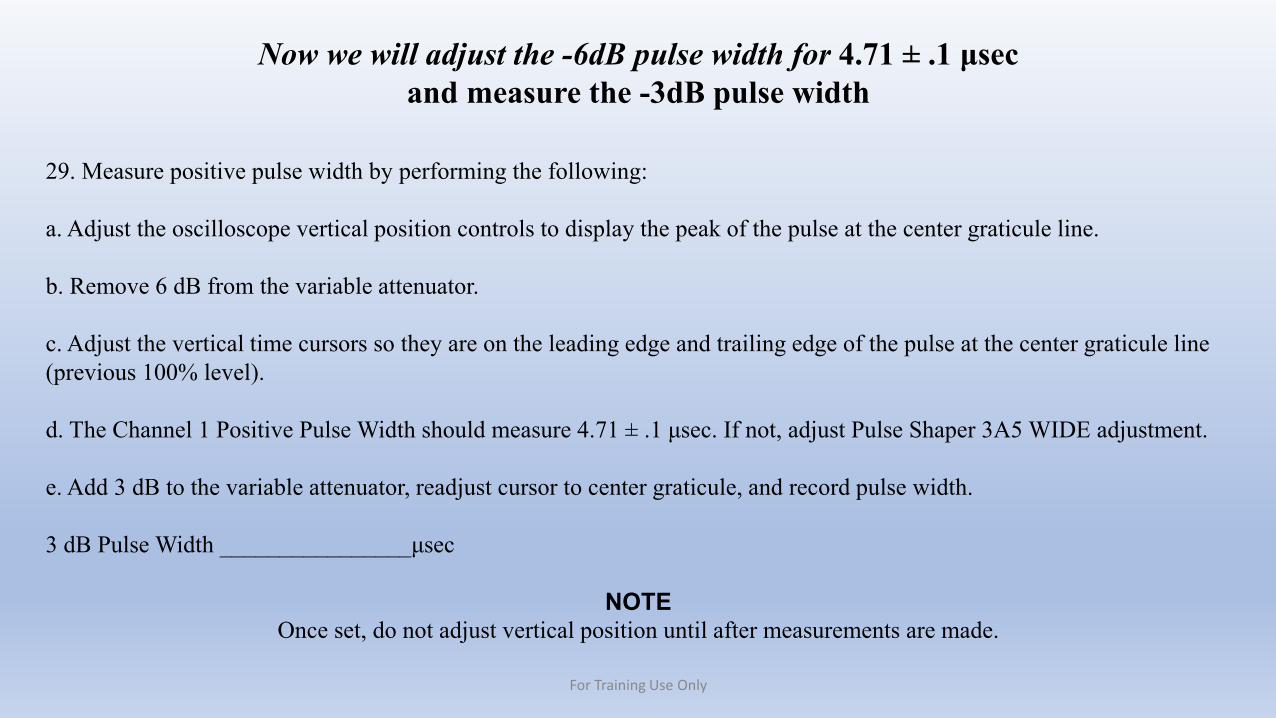
29. Measure positive pulse width by performing the following:
a. Adjust the oscilloscope vertical position controls to display the peak of the pulse at the center graticule line.
b. Remove 6 dB from the variable attenuator.
c. Adjust the vertical time cursors so they are on the leading edge and trailing edge of the pulse at the center graticule line (previous 100% level).
d. The Channel 1 Positive Pulse Width should measure 4.71 ± .1 μsec. If not, adjust Pulse Shaper 3A5 WIDE adjustment.
e. Add 3 dB to the variable attenuator, readjust cursor to center graticule, and record pulse width.
3 dB Pulse Width ________________μsec
NOTEOnce set, do not adjust vertical position until after measurements are made.
Now we will adjust the -6dB pulse width for 4.71 ± .1 μsecand measure the -3dB pulse width
For Training Use Only
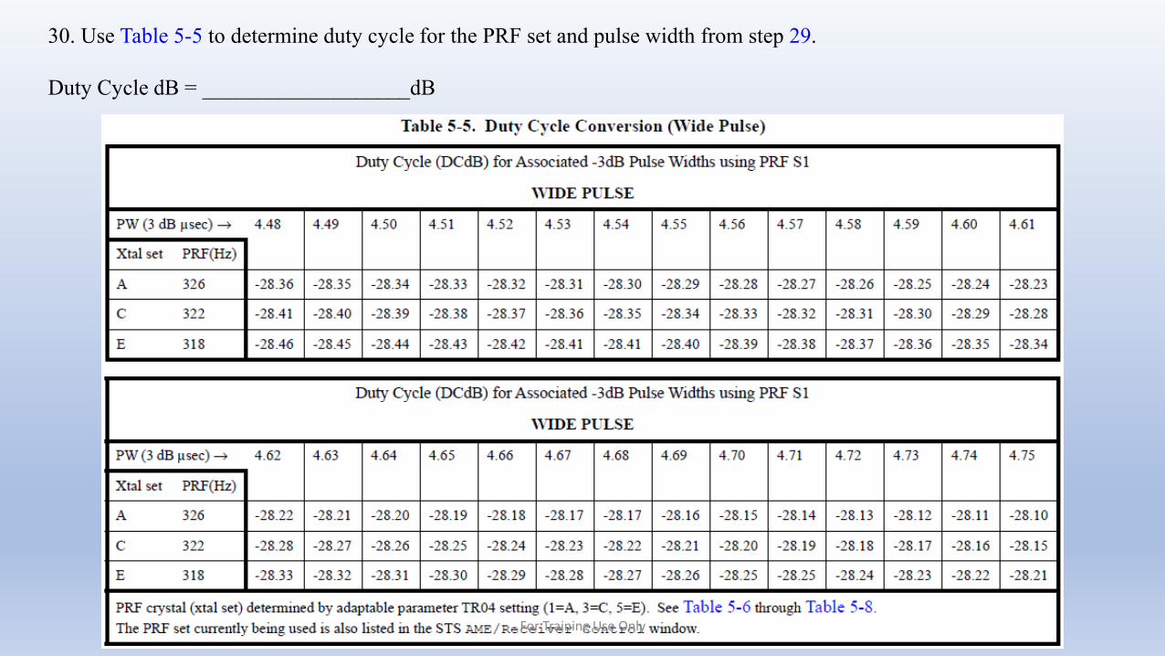
30. Use Table 5-5 to determine duty cycle for the PRF set and pulse width from step 29.
Duty Cycle dB = ___________________dB
For Training Use Only
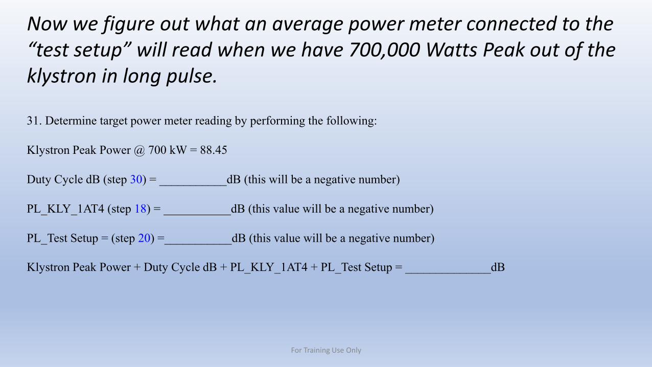
Now we figure out what an average power meter connected to the “test setup” will read when we have 700,000 Watts Peak out of the klystron in long pulse.
31. Determine target power meter reading by performing the following:
Klystron Peak Power @ 700 kW = 88.45
Duty Cycle dB (step 30) = ___________dB (this will be a negative number)
PL_KLY_1AT4 (step 18) = ___________dB (this value will be a negative number)
PL_Test Setup = (step 20) =___________dB (this value will be a negative number)
Klystron Peak Power + Duty Cycle dB + PL_KLY_1AT4 + PL_Test Setup = ______________dB
For Training Use Only
32. At Transmitter Control Panel A1, refine the power meter measurement by adjusting the PFN voltage potentiometer A1R3. Increase or decrease PFN to reach the targeted value from step
31. Do not exceed 5200V. Nominal PFN meter reading is 4800V.
33. Measure 3 dB pulse width. Record this value in nsec. This measurement will become adaptable parameter TR6.
Example: 3 dB Pulse Width = 4.71 μS (tr06 = 4710 nsec)
3 dB Pulse Width = ________________nsec
NWSTC note: TR6 is the adaptation data value that the computer uses for power calculations in long pulse
34. In the AME/Receiver Control window, select the following:
Test Source: NONEClick: Inject Signal
For Training Use Only
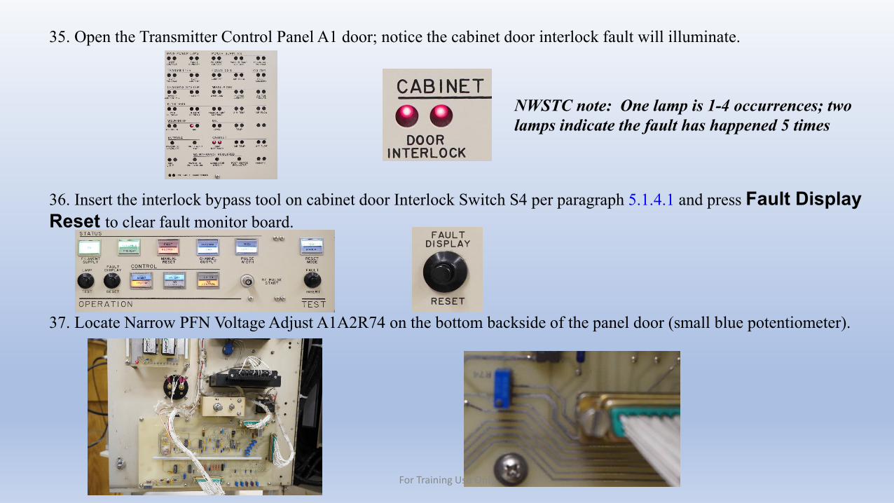
35. Open the Transmitter Control Panel A1 door; notice the cabinet door interlock fault will illuminate.
36. Insert the interlock bypass tool on cabinet door Interlock Switch S4 per paragraph 5.1.4.1 and press Fault Display Reset to clear fault monitor board.
37. Locate Narrow PFN Voltage Adjust A1A2R74 on the bottom backside of the panel door (small blue potentiometer).
NWSTC note: One lamp is 1-4 occurrences; two lamps indicate the fault has happened 5 times
For Training Use Only
38. In the AME/Receiver Control window, select the following:
Test Source: KLYSTRON OUTPUTPulse Width: Short PulsePRF: S1Click: Inject Signal
39. Tuning potentiometer A1A2R74 will increase or decrease peak power for short pulse approximately 40 kW. CW turns increase power and CCW turns decrease. Turn potentiometer A1A2R74 to increase or decrease according to the readings in step 22.
40. In the AME/Receiver Control window, select the following:Test Source: NONEClick: Inject Signal
We set the transmitter up for 700KW in short pulse.We then set the power of the transmitter in long pulse by adjusting A1R3.
When we return to short pulse, the only thing that has been changed is the PFN voltage.A1A2R74 is the offset for long and short PFN voltage. This adjustment allows us to stay closer to 700KW in both widths.
For Training Use Only
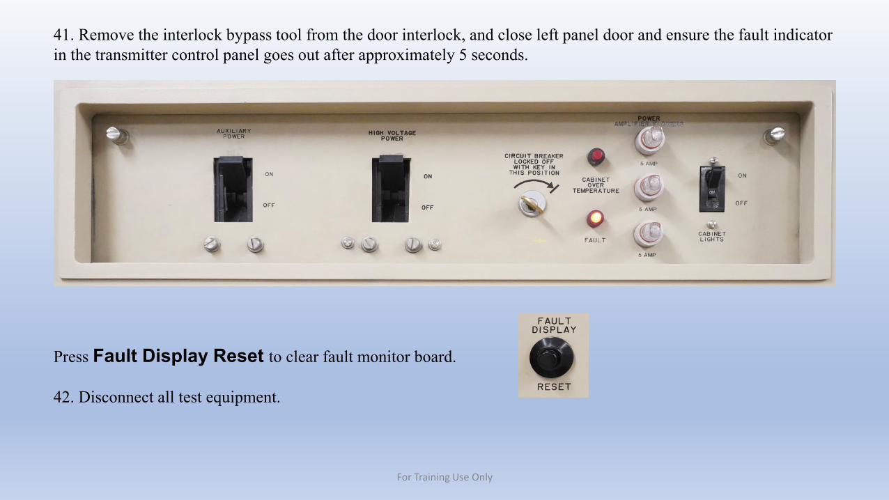
41. Remove the interlock bypass tool from the door interlock, and close left panel door and ensure the fault indicator in the transmitter control panel goes out after approximately 5 seconds.
Press Fault Display Reset to clear fault monitor board.
42. Disconnect all test equipment.
For Training Use Only
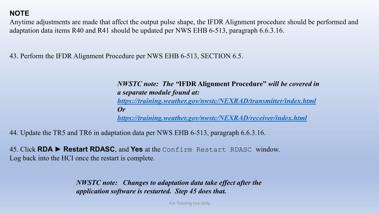
NOTEAnytime adjustments are made that affect the output pulse shape, the IFDR Alignment procedure should be performed and adaptation data items R40 and R41 should be updated per NWS EHB 6-513, paragraph 6.6.3.16.
43. Perform the IFDR Alignment Procedure per NWS EHB 6-513, SECTION 6.5.
44. Update the TR5 and TR6 in adaptation data per NWS EHB 6-513, paragraph 6.6.3.16.
45. Click RDA ► Restart RDASC, and Yes at the Confirm Restart RDASC window.Log back into the HCI once the restart is complete.
NWSTC note: The “IFDR Alignment Procedure” will be covered in a separate module found at:https://training.weather.gov/nwstc/NEXRAD/transmitter/index.htmlOrhttps://training.weather.gov/nwstc/NEXRAD/receiver/index.html
NWSTC note: Changes to adaptation data take effect after the application software is restarted. Step 45 does that.
For Training Use Only
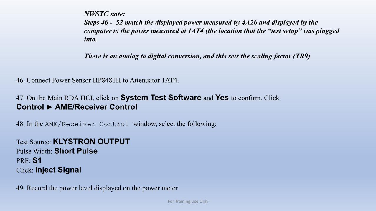
NWSTC note: Steps 46 - 52 match the displayed power measured by 4A26 and displayed by the computer to the power measured at 1AT4 (the location that the “test setup” was plugged into.
There is an analog to digital conversion, and this sets the scaling factor (TR9)
46. Connect Power Sensor HP8481H to Attenuator 1AT4.
47. On the Main RDA HCI, click on System Test Software and Yes to confirm. ClickControl ► AME/Receiver Control.
48. In the AME/Receiver Control window, select the following:
Test Source: KLYSTRON OUTPUTPulse Width: Short PulsePRF: S1Click: Inject Signal
49. Record the power level displayed on the power meter.
For Training Use Only
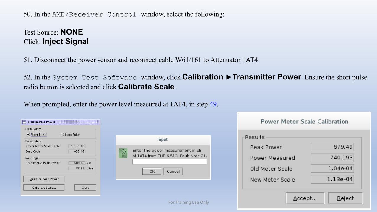
50. In the AME/Receiver Control window, select the following:
Test Source: NONEClick: Inject Signal
51. Disconnect the power sensor and reconnect cable W61/161 to Attenuator 1AT4.
52. In the System Test Software window, click Calibration ►Transmitter Power. Ensure the short pulse radio button is selected and click Calibrate Scale.
When prompted, enter the power level measured at 1AT4, in step 49.
For Training Use Only
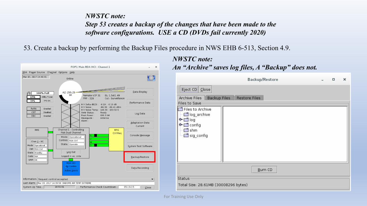
NWSTC note: Step 53 creates a backup of the changes that have been made to the software configurations. USE a CD (DVDs fail currently 2020)
53. Create a backup by performing the Backup Files procedure in NWS EHB 6-513, Section 4.9. NWSTC note: An “Archive” saves log files, A “Backup” does not.
For Training Use Only
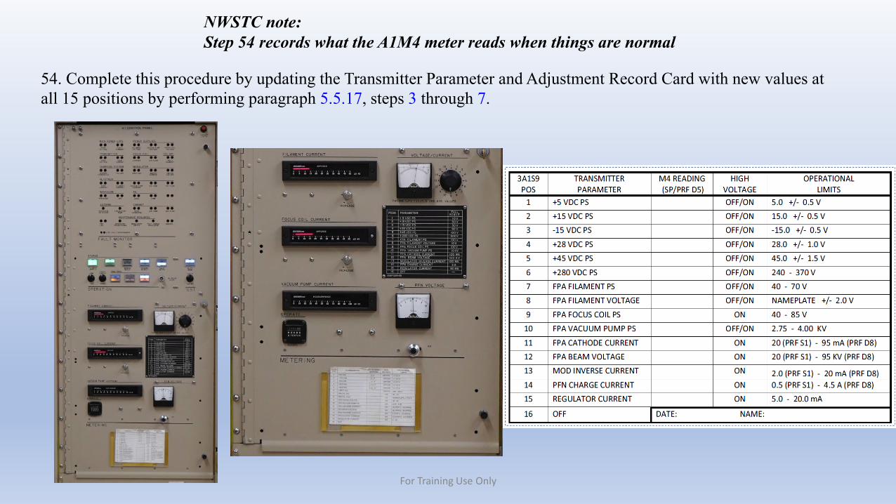
54. Complete this procedure by updating the Transmitter Parameter and Adjustment Record Card with new values at all 15 positions by performing paragraph 5.5.17, steps 3 through 7.
NWSTC note: Step 54 records what the A1M4 meter reads when things are normal
For Training Use Only