Kinetic Monte Carlo Simulations of Defect Nano … with Applications to Dislocation Dynamics in ......
148
University of California Los Angeles Kinetic Monte Carlo Simulations of Defect Nano-mechanics with Applications to Dislocation Dynamics in Irradiated α-Iron A dissertation submitted in partial satisfaction of the requirements for the degree Doctor of Philosophy in Mechanical Engineering by Ming Wen 2005
Transcript of Kinetic Monte Carlo Simulations of Defect Nano … with Applications to Dislocation Dynamics in ......
University of California
Los Angeles
Kinetic Monte Carlo Simulations of Defect
Nano-mechanics with Applications to
Dislocation Dynamics in Irradiated α-Iron
A dissertation submitted in partial satisfaction
of the requirements for the degree
Doctor of Philosophy in Mechanical Engineering
by
Ming Wen
2005

The dissertation of Ming Wen is approved.
D.C.H. Yang
J.-W. Ju
G.P. Carman
N.M. Ghoniem, Committee Chair
University of California, Los Angeles
2005
ii
To my parents and my wife . . .
for their love and support
iii
Table of Contents
1 INTRODUCTION . . . . . . . . . . . . . . . . . . . . . . . . . . . . 1
1.1 EFFECTS OF NEUTRON IRRADIATION ON MECHANICAL
PROPERTIES OF MATERIALS . . . . . . . . . . . . . . . . . . 1
1.2 DEFINITIONS AND TERMINOLOGY . . . . . . . . . . . . . . 5
1.3 SCOPE OF THIS THESIS . . . . . . . . . . . . . . . . . . . . . . 8
2 EVIDENCE OF DISLOCATION DECORATION AND RAFTS 9
2.1 EXPERIMENTAL OBSERVATIONS . . . . . . . . . . . . . . . . 10
2.2 THEORETICAL ANALYSIS ON MECHANISMS OF DISLOCA-
TION DECORATION AND RADIATION HARDENING . . . . 14
3 REVIEW OF KINETIC MONTE CARLO METHOD . . . . . 19
3.1 INTRODUCTION . . . . . . . . . . . . . . . . . . . . . . . . . . 19
3.2 THE N -FOLD WAY ALGORITHM . . . . . . . . . . . . . . . . 20
3.3 KINETIC MONTE CARLO METHOD . . . . . . . . . . . . . . . 22
4 ELASTIC REPRESENTATION OF DEFECTS . . . . . . . . . 27
4.1 KRONER’S DESCRIPTION OF POINT DEFECTS BY FORCE
MULTIPOLES . . . . . . . . . . . . . . . . . . . . . . . . . . . . 27
4.2 ELASTIC INTERACTION BETWEEN DEFECTS . . . . . . . . 32
4.3 REPRESENTATION OF NANO-DEFECTS BY FORCE DIPOLES 36
4.4 APPLICATIONS . . . . . . . . . . . . . . . . . . . . . . . . . . . 39
4.4.1 VACANCY . . . . . . . . . . . . . . . . . . . . . . . . . . 39
iv
4.4.2 INFINITESIMAL PRISMATIC DISLOCATION LOOP . . 40
5 DEVELOPMENT OF NEW COMPUTATIONAL MODELS FOR
RADIATION DAMAGE ACCUMULATION AND SEGREGATION
42
5.1 INTRODUCTION . . . . . . . . . . . . . . . . . . . . . . . . . . 42
5.2 A KINETIC MONTE CARLO APPROACH TO RADIATION
DAMAGE EVOLUTION WITH ELASTIC INTERACTION CON-
SIDERATION . . . . . . . . . . . . . . . . . . . . . . . . . . . . . 43
5.3 MAIN MODEL FEATURES . . . . . . . . . . . . . . . . . . . . . 47
5.3.1 Displacement Cascade Simulations . . . . . . . . . . . . . 49
5.3.2 DISLOCATION DECORATION . . . . . . . . . . . . . . 53
5.3.3 PINNING AND SMALL RAFTS OF SMALL INTERSTI-
TIAL LOOPS . . . . . . . . . . . . . . . . . . . . . . . . . 58
5.4 VALIDITY OF ELASTIC APPROXIMATION- MD SIMULA-
TION VS ELASTICITY CALCULATION . . . . . . . . . . . . . 62
6 KINETIC MONTE CARLO SIMULATION OF RADIATION
DAMAGE EVOLUTION IN α-IRON . . . . . . . . . . . . . . . . . . 65
6.1 INPUT PARAMETERS TO KINETIC MONTE CARLO SIMU-
LATION . . . . . . . . . . . . . . . . . . . . . . . . . . . . . . . . 65
6.2 DOSE DEPENDENCE OF DEFECT DENSITY . . . . . . . . . 69
6.3 CHARACTERISTICS OF DECORATION AND RAFT FORMA-
TION . . . . . . . . . . . . . . . . . . . . . . . . . . . . . . . . . 74
v
6.4 GENERAL CONDITIONS FOR DECORATION AND RAFT FOR-
MATION . . . . . . . . . . . . . . . . . . . . . . . . . . . . . . . 81
7 EFFECTS OF NEUTRON IRRADIATION ON DYNAMIC PROP-
ERTIES OF EDGE DISLOCATIONS . . . . . . . . . . . . . . . . . . 82
7.1 INTRODUCTION . . . . . . . . . . . . . . . . . . . . . . . . . . 82
7.2 PARAMETRIC DISLOCATION DYNAMICS . . . . . . . . . . . 84
7.2.1 THE EQUATION OF MOTION . . . . . . . . . . . . . . 86
7.2.2 THE MASS OF DISLOCATIONS . . . . . . . . . . . . . . 93
7.3 THE DRAG COEFFICIENT OF INTERSTITIAL LOOP DRAGGED
BY A GLIDING DISLOCATION . . . . . . . . . . . . . . . . . . 96
7.4 IRRADIATION-INDUCED INCREASE IN THE YIELD STRESS 101
7.4.1 THE PLANE GLIDE RESISTANCE (FRIEDEL STATIS-
TICS) DUE TO VACANCIES . . . . . . . . . . . . . . . . 102
7.4.2 INTERACTION BETWEEN A STRAIGHT EDGE DIS-
LOCATION AND SIA CLUSTER DECORATIONS . . . 107
7.5 VELOCITY OF EDGE DISLOCATIONS IN NEUTRON-IRRADIATED
BCC IRON . . . . . . . . . . . . . . . . . . . . . . . . . . . . . . 112
8 CONCLUSIONS . . . . . . . . . . . . . . . . . . . . . . . . . . . . . 118
References . . . . . . . . . . . . . . . . . . . . . . . . . . . . . . . . . . . 122
vi
List of Figures
1.1 Experimental stress-strain curves for irradiated and unirradiated
copper. Specimens were irradiated in the DR-3 reactor at Risø
National Laboratory at 320 K, and tensile tested at 295 and 320K
[8]. . . . . . . . . . . . . . . . . . . . . . . . . . . . . . . . . . . . 2
1.2 Experimental stress-strain curves for irradiated and unirradiated
pure iron. Irradiations were conducted in the High Flux Isotope
Reactor (HFIR) at Oak Ridge National Laboratory (ORNL) at
about 70 C, and tensile tested at 70 C. [9]. . . . . . . . . . . . . 2
1.3 Example of cleared dislocation channels formed in pure iron irra-
diated at 320 K to 3.75 × 10⁻¹ dpa and tensile tested at 320 K
[13]. . . . . . . . . . . . . . . . . . . . . . . . . . . . . . . . . . . 4
2.1 Idealized representation of an side view of prismatic edge disloca-
tion loops comprising a raft . . . . . . . . . . . . . . . . . . . . . 11
2.2 Dislocation structure in Nickel 270 irradiated to a fluence of 3.2×10¹⁹ neutron/cm2 [28]. . . . . . . . . . . . . . . . . . . . . . . . . 13
3.1 Schematic representation of various competing thermally activated
diffusional processes. The large sectors represent jump paths with
large jump rates and vice versa. . . . . . . . . . . . . . . . . . . . 24
4.1 Schematic representation of lattice deformation induced by the
occurrence of a defect, as well as the point forces approximation. . 28
5.1 Kinetic MC Implementation of the damage evolution of cascade-
induced defect clusters. . . . . . . . . . . . . . . . . . . . . . . . . 46
vii
5.2 Primary damage state at 17 ps for a 100 KeV cascade: (©) inter-
stitials; (•) vacancies. . . . . . . . . . . . . . . . . . . . . . . . . . 51
5.3 A close view of the structure of one single cascade at t = 94 ps.
Small circular loops represent SIA clusters, and solid points repre-
sent vacancies. . . . . . . . . . . . . . . . . . . . . . . . . . . . . . 52
5.4 TEM micrograph of pure Fe irradiated with fission neutrons at 70
oC to a displacement dose level of 0.72 dpa. . . . . . . . . . . . . 55
5.5 KMC simulation results of 200 SIA clusters in the stress field of
a 3-D dislocation loop. Burgers vector of the slip dislocation is
along [1 1 1] direction and the temperature is 300 K. SIA clusters
are clearly observed to accumulate along the edge components of
the loop. (a) 0 ns; (b) 0.1 ns; (3) 0.3 ns; (d) 0.4 ns. . . . . . . . . 56
5.6 KMC simulation results of 200 SIA clusters with no interaction
between SIA clusters and the 3-D dislocation loop. Burgers vector
of the slip dislocation is along [1 1 1] direction and the temperature
is 300 K. Dislocation decoration is not observed. . . . . . . . . . . 57
5.7 KMC simulation of 200 SIA clusters in the stress field of a 3-D
dislocation loop. Burgers vector of the slip dislocation is along [1 1
1] direction and the temperature is 300 K. Dislocation decoration
and SIA cluster rafts are clearly observed, as indicated by the
arrows. (a) 0 ns; (b) 0.4 ns; (3) 0.7 ns; (d) 1.0 ns. . . . . . . . . . 60
5.8 Interaction energy between 12[111] edge dislocation and 37-SIA
prismatic cluster in bcc Fe as a function of distance along [110]
direction. Simulation results are compared with the interaction
energy evaluated by infinitesimal loop approximation. . . . . . . . 64
viii
6.1 Centre-of-mass trajectories of a 6-SIA cluster migration for 10000
consecutive steps. . . . . . . . . . . . . . . . . . . . . . . . . . . . 68
6.2 Dose dependence of the total SIA cluster density in bcc Fe: -©-,
no recombination; -- with recombination. . . . . . . . . . . . . . 70
6.3 Dose dependence of the total visible SIA cluster density in bcc Fe:
-©-, KMC simulation results; -4- experimental results of Eldrup
et al. (2002); -5- experimental results of Singh et al. (1999). . . . 71
6.4 Size distribution of SIA clusters at a dose level of 5.21 × 10⁻³ dpa. 73
6.5 Spatial distribution of SIA clusters in bcc Fe at 300 K, (a) 1.3×10⁻³
dpa, (b) 5.2 × 10⁻³. . . . . . . . . . . . . . . . . . . . . . . . . . . 75
6.6 (a) Local iso-energy contours for the interaction energy of a SIA
cluster of Burgers vector a/2[1 1 1] with an edge dislocation on
the (1 2 1) -plane in bcc iron; (b) local iso-energy contours of
the interaction energy of an interstitial defect clusters of Burgers
vector a/2[1 1 1] with a pre-existing same type cluster and an edge
dislocation on the (1 2 1) -plane. Contours are plotted at 0.02 (in
µδA/(1 − ν), where µ is the shear modulus and δA is the surface
area of the SIA cluster) increment. The length on the axes is in
units of lattice constant, a. . . . . . . . . . . . . . . . . . . . . . . 76
6.7 A close-up view of the configuration of a raft of interstitial clusters
formed at a dose level of 1.8 × 10⁻³ dpa. The raft is enclosed in a
dotted circle. . . . . . . . . . . . . . . . . . . . . . . . . . . . . . 77
ix
6.8 The glide force between two prismatic dislocation loops with par-
allel Burgers vectors as a function of their relative positions. The
force is scaled by µb1b2A1A2/4π(1−ν)d4, where bi and Ai (i = 1, 2)
are the Burgers vectors and surface areas of the two loops, respec-
tively. . . . . . . . . . . . . . . . . . . . . . . . . . . . . . . . . . 79
6.9 Force field distribution along the glide direction of an existing raft
of SIA clusters (in solid lines). Two new SIA clusters (in dashed
line) which will join the raft are also shown. . . . . . . . . . . . . 80
7.1 Parametric representation of a general curved dislocation segment,
with relevant vector defined (after [104]). . . . . . . . . . . . . . . 85
7.2 Representation of dislocation loop motion in an infinitesimal tran-
sition, illustrating thermodynamic variables (after [102]). . . . . . 87
7.3 Velocity of an edge dislocation as a function of time under suddenly
applied uniaxial tensile stress σ1 = 2 GPa. . . . . . . . . . . . . . 91
7.4 Drag coefficient versus applied resolved shear stress for single (grey
symbols) and decorated (open symbols) dislocations in Fe (circle)
and Cu (triangles) simulated at 300 K[103]. . . . . . . . . . . . . 97
7.5 Schematic illustration of the investigated system. . . . . . . . . . 98
7.6 Spatial distribution obtained by KMC simulations for SIA loops
that can be dragged by the edge component of the dislocation loop
in bcc Fe irradiated to a dose of 5.2 × 10⁻³ dpa at 300 K. . . . . . 101
7.7 Schematic of shape of dislocation line near the Orowan-type ob-
stacles. . . . . . . . . . . . . . . . . . . . . . . . . . . . . . . . . . 103
x
7.8 The dependence of the plane glide resistance in terms of critical
shear stress on the volume fraction of nano-voids for an edge dis-
location in neutron irradiated bcc iron. . . . . . . . . . . . . . . . 105
7.9 Spatial distribution obtained by KMC simulations for SIA loops
that is in the region of decoration of the dislocation loop in bcc
iron irradiated to a dose of 5.2 × 10⁻³ dpa at 300 K. . . . . . . . . 108
7.10 Dynamics of an edge dislocation interaction with a distribution of
SIA clusters in bcc iron. The Burgers vector of the dislocation is
b = 12[111], and the configuration of cluster is produced by KMC
simulations, as in Figure 7.9. . . . . . . . . . . . . . . . . . . . . . 110
7.11 Dose dependence of the increase in yield stress due to the interac-
tion with clusters in decoration as well as the distributed vacancy
clusters (nano-voids) in bcc iron irradiated at 300 K. Numerical
results are compared with the experimental data of pure iron irra-
diated and tested at 70 C[9]. . . . . . . . . . . . . . . . . . . . . 111
7.12 Time dependence of dislocation velocity in bcc iron under applied
uniaxial tensile stress for an edge dislocation interacting with SIA
clusters in decoration, penetrating through decoration atmosphere
and breaking away from dragged interstitial clusters. Vertical ar-
rows indicate velocities at which certain dragged clusters detaches
from the moving edge dislocation. . . . . . . . . . . . . . . . . . . 113
7.13 Velocity of an edge dislocation as a function of time under dif-
ferent applied uniaxial tensile stresses σ11 larger than the plane
glide resistance due to randomly distributed nano-voids in bcc Fe
irradiated to a dose of 5.2 × 10⁻³ dpa. . . . . . . . . . . . . . . . 116
xi
List of Tables
5.1 Evolution time for Running 800,000 KMC Steps (in ns). . . . . . 61
7.1 Values of Bloop predicted by Equation 7.37 and vmax obtained from
Equation 7.38 for an edge dislocation to break away from the
dragged loops. . . . . . . . . . . . . . . . . . . . . . . . . . . . . . 117
xii

Acknowledgments
xiii
Vita
1974 Born, Jianshi County, Hubei Province, China.
1991-1996 B.S., Engineering Mechanics, Tsinghua University, Beijing,
China.
2000-2005 PhD, Mechanical and Aerospace Engineering, University of Cal-
ifornia, Los Angeles, USA.
Publications
Ming Wen, Nasr M. Ghoniem and Bachu N. Singh, ”Dislocation Decoration
and Raft Formation in Irradiated Materials”, Philosophical Magazine A, 85(22):
(2005) 2561-2580.
Nasr M. Ghoniem, Shih-Hsi Tong, Jianming Huang, Bach N. Singh and Ming
Wen, ”Mechanisms of Dislocation-Defect Interactions in Irradiated Metals Inves-
tigated by Computer Simulations”, Journal of Nuclear Materials, 307-311: (2002)
843-851.
Ming Wen, C.H. Woo and Hanchen Huang, ”Atomistic Studies of Stress Effects
on Self-Interstitial Diffusion in α-Titanium”, Journal of Computer-Aided Mate-
rials Design, 7(2): (2000) 97-110.
xiv
Ming Wen, Quan-Shui Zheng, and Danxu Du, ”Some Basic Problems in Numer-
ically Simulating Effective Properties and Local Fields of Composite Materials”,
Acta Mechanica Solida Sinica, 12(4): (1999) 328-339.
xv
Abstract of the Dissertation
Kinetic Monte Carlo Simulations of Defect
Nano-mechanics with Applications to
Dislocation Dynamics in Irradiated α-Iron
by
Ming Wen
Doctor of Philosophy in Mechanical Engineering
University of California, Los Angeles, 2005
Professor N.M. Ghoniem, Chair
Experimental observations of dislocation decoration with Self Interstitial Atom
(SIA) clusters, and of SIA cluster rafts are analyzed to establish the mechanisms
controlling these phenomena in bcc metals. The elastic interaction between SIA
clusters, and between clusters and dislocations is included in Kinetic Monte Carlo
(KMC) simulations of damage evolution in irradiated bcc metals. The results in-
dicate that SIA clusters, which normally migrate by 1-D glide, rotate due to their
elastic interactions, and that this rotation is necessary to explain experimentally-
observed dislocation decoration and raft formation in neutron-irradiated pure
iron. The critical dose for raft formation in iron is shown to depend on the in-
trinsic glide/ rotation characteristics of SIA clusters. The model is compared
with experimental observations for the evolution of defect cluster densities (ses-
sile SIA clusters and nano-voids), dislocation decoration characteristics, and the
conditions for raft formation.
xvi
Nasr Ghoniem
Pencil
Nasr Ghoniem
Pencil
Nasr Ghoniem
Pencil
CHAPTER 1
INTRODUCTION
1.1 EFFECTS OF NEUTRON IRRADIATION ON ME-
CHANICAL PROPERTIES OF MATERIALS
With the constant increase in energy consumption, nuclear power has been regain-
ing stature as a serious alternative energy source other than fossil fuel. Among
all the debates surrounding nuclear energy, safety issue is no doubt one of the
biggest concerns. Most materials experience dramatic mechanical and physical
property changes when irradiated by energetic particles such as fission or fusion
neutrons [1]. Radiation damage plays a decisive role in the lifetime and safety of
components used in current fission power plants, and thus indirectly affects the
economy of fission power. For proposed future fusion reactors, radiation damage
caused by the interaction of fusion plasma ions and neutron-induced recoils with
the first walls, structures, and other functional materials is a major challenge in
the realization of fusion power [2, 3, 4, 5, 6, 7].
It is well established that neutron irradiation causes a substantial amount
of hardening and changes significantly the deformation behavior of metals and
alloys, particularly at irradiation temperatures below the recovery stage V (i.e.
< 0.4 Tm where Tm is the melting temperature). Since the early investigation
of irradiation hardening by McReynolds et al. [10] and Bleweitt et al. [11], the
effect of irradiation on mechanical properties has been a subject of extensive
1
Nasr Ghoniem
Pencil
Nasr Ghoniem
Pencil
Nasr Ghoniem
Pencil
Nasr Ghoniem
Pencil
Nasr Ghoniem
Pencil
Nasr Ghoniem
Pencil
Nasr Ghoniem
Pencil
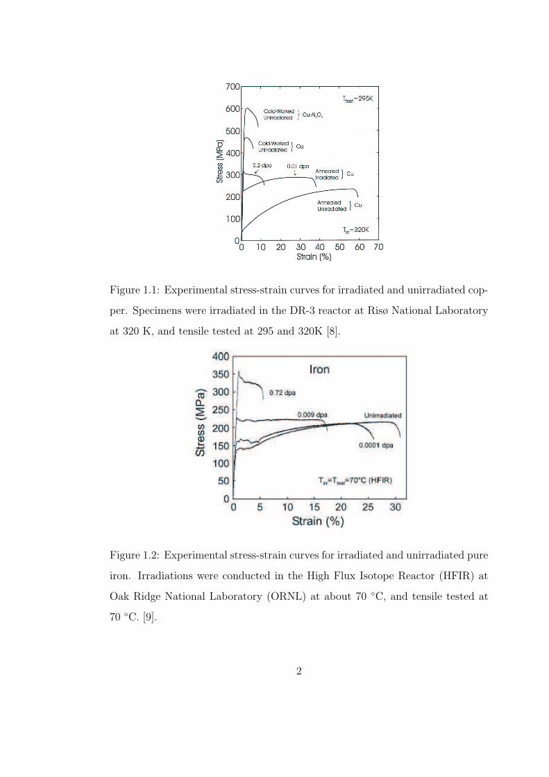
Figure 1.1: Experimental stress-strain curves for irradiated and unirradiated cop-
per. Specimens were irradiated in the DR-3 reactor at Risø National Laboratory
at 320 K, and tensile tested at 295 and 320K [8].
Figure 1.2: Experimental stress-strain curves for irradiated and unirradiated pure
iron. Irradiations were conducted in the High Flux Isotope Reactor (HFIR) at
Oak Ridge National Laboratory (ORNL) at about 70 C, and tensile tested at
70 C. [9].
2
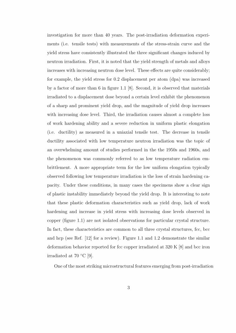
investigation for more than 40 years. The post-irradiation deformation experi-
ments (i.e. tensile tests) with measurements of the stress-strain curve and the
yield stress have consistently illustrated the three significant changes induced by
neutron irradiation. First, it is noted that the yield strength of metals and alloys
increases with increasing neutron dose level. These effects are quite considerably;
for example, the yield stress for 0.2 displacement per atom (dpa) was increased
by a factor of more than 6 in figure 1.1 [8]. Second, it is observed that materials
irradiated to a displacement dose beyond a certain level exhibit the phenomenon
of a sharp and prominent yield drop, and the magnitude of yield drop increases
with increasing dose level. Third, the irradiation causes almost a complete loss
of work hardening ability and a severe reduction in uniform plastic elongation
(i.e. ductility) as measured in a uniaxial tensile test. The decrease in tensile
ductility associated with low temperature neutron irradiation was the topic of
an overwhelming amount of studies performed in the the 1950s and 1960s, and
the phenomenon was commonly referred to as low temperature radiation em-
brittlement. A more appropriate term for the low uniform elongation typically
observed following low temperature irradiation is the loss of strain hardening ca-
pacity. Under these conditions, in many cases the specimens show a clear sign
of plastic instability immediately beyond the yield drop. It is interesting to note
that these plastic deformation characteristics such as yield drop, lack of work
hardening and increase in yield stress with increasing dose levels observed in
copper (figure 1.1) are not isolated observations for particular crystal structure.
In fact, these characteristics are common to all three crystal structures, fcc, bcc
and hcp (see Ref. [12] for a review). Figure 1.1 and 1.2 demonstrate the similar
deformation behavior reported for fcc copper irradiated at 320 K [8] and bcc iron
irradiated at 70 C [9].
One of the most striking microstructural features emerging from post-irradiation
3
Nasr Ghoniem
Pencil
Nasr Ghoniem
Pencil
Nasr Ghoniem
Pencil
Nasr Ghoniem
Pencil
Nasr Ghoniem
Pencil
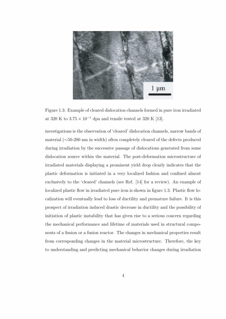
Figure 1.3: Example of cleared dislocation channels formed in pure iron irradiated
at 320 K to 3.75 × 10⁻¹ dpa and tensile tested at 320 K [13].
investigations is the observation of ‘cleared’ dislocation channels, narrow bands of
material (∼50-200 nm in width) often completely cleared of the defects produced
during irradiation by the successive passage of dislocations generated from some
dislocation source within the material. The post-deformation microstructure of
irradiated materials displaying a prominent yield drop clearly indicates that the
plastic deformation is initiated in a very localized fashion and confined almost
exclusively to the ‘cleared’ channels (see Ref. [14] for a review). An example of
localized plastic flow in irradiated pure iron is shown in figure 1.3. Plastic flow lo-
calization will eventually lead to loss of ductility and premature failure. It is this
prospect of irradiation induced drastic decrease in ductility and the possibility of
initiation of plastic instability that has given rise to a serious concern regarding
the mechanical performance and lifetime of materials used in structural compo-
nents of a fission or a fusion reactor. The changes in mechanical properties result
from corresponding changes in the material microstructure. Therefore, the key
to understanding and predicting mechanical behavior changes during irradiation
4
relies on having a detailed understanding of both the materials microstructure
evolution during irradiation and the connection between microstructure and me-
chanical properties.
1.2 DEFINITIONS AND TERMINOLOGY
A number of important physical phenomena take place when energetic parti-
cles penetrate through solids. Those macroscopic, observable, and often techno-
logically significant results induced by the bombarding particles are collectively
know as radiation effects.The area of radiation damage and effects is concerned
with the investigation of microscopic and macroscopic phenomena resulting from
the immediate interaction of high-energy particle with solid materials. The mi-
crostructure of irradiated materials evolves over a wide range of length and time
scales, making radiation damage an inherently multiscale phenomenon.
In a fission or fusion reactor, neutrons will transfer substantial energy to a sta-
tionary lattice atom in a collision, which is of the order of hundreds to thousands
of kiloelectron volts (KeV). This amount of energy is so much greater than the
energy binding the atom in its lattice site, namely the displacement thresh-
old energy, that the struck atom is permanently displaced from its equilibrium
lattice site. The empty lattice site left behind by the displaced atom is called a
vacancy. The displaced atom which is situated between the normal sites of the
lattice is referred to as an interstitial. If an interstitial atom is of the same na-
ture with the atoms of the matrix lattice, it is said to be a self-interstitial atom
(SIA). The combination of an interstitial and a vacancy is termed a Frenkel pair.
The lattice atom first stuck and displaced by the incident particle possesses is
called the primary knock-on atom, or PKA. A PKA can possesses enough en-
5
Nasr Ghoniem
Pencil
Nasr Ghoniem
Pencil
Nasr Ghoniem
Pencil
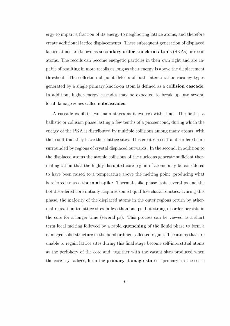
ergy to impart a fraction of its energy to neighboring lattice atoms, and therefore
create additional lattice displacements. These subsequent generation of displaced
lattice atoms are known as secondary order knock-on atoms (SKAs) or recoil
atoms. The recoils can become energetic particles in their own right and are ca-
pable of resulting in more recoils as long as their energy is above the displacement
threshold. The collection of point defects of both interstitial or vacancy types
generated by a single primary knock-on atom is defined as a collision cascade.
In addition, higher-energy cascades may be expected to break up into several
local damage zones called subcascades.
A cascade exhibits two main stages as it evolves with time. The first is a
ballistic or collision phase lasting a few tenths of a picosencond, during which the
energy of the PKA is distributed by multiple collisions among many atoms, with
the result that they leave their lattice sites. This creates a central disordered core
surrounded by regions of crystal displaced outwards. In the second, in addition to
the displaced atoms the atomic collisions of the nucleons generate sufficient ther-
mal agitation that the highly disrupted core region of atoms may be considered
to have been raised to a temperature above the melting point, producing what
is referred to as a thermal spike. Thermal-spike phase lasts several ps and the
hot disordered core initially acquires some liquid-like characteristics. During this
phase, the majority of the displaced atoms in the outer regions return by ather-
mal relaxation to lattice sites in less than one ps, but strong disorder persists in
the core for a longer time (several ps). This process can be viewed as a short
term local melting followed by a rapid quenching of the liquid phase to form a
damaged solid structure in the bombardment affected region. The atoms that are
unable to regain lattice sites during this final stage become self-interstitial atoms
at the periphery of the core and, together with the vacant sites produced when
the core crystallizes, form the primary damage state - ‘primary’ in the sense
6
Nasr Ghoniem
Pencil
Nasr Ghoniem
Pencil
Nasr Ghoniem
Pencil
Nasr Ghoniem
Pencil
Nasr Ghoniem
Pencil
Nasr Ghoniem
Pencil
that damage is produced directly in displacement cascade - of irradiation during
this short time frame [15]. Following the quenching stage of thermal spike, fur-
ther rearrangement and interaction of the surviving defects take place by normal,
thermally-activated diffusion of mobile defects.
Radiation damage is not restricted to the isolated point defects produced by
the incident particles. Actually, vacancies and interstitials can be produced so
close to each other that clustering of the point defects takes place spontaneously
within the short time frame of the primary damage state. The point defect
clusters created in displacement cascades can be thermally stable and behave
very differently from the component individual point defect in a kinematic sense.
Because of the proximity of point defects in a displacement cascade, a large
portion of the point defects produced by the high-energy collision are almost in-
stantaneously annihilated by the spontaneous recombination of unstable Frenkel
pairs within their nascent cascade. In fact, the fraction of point defects, which
actually survives a cascade and is capable of producing observable radiation ef-
fects, is of the most interest. The point defects and some of their clusters become
mobile by thermal activation at elevated temperature. Therefore, soon after pro-
duction in cascades some defects will be able to escape their nascent cascade
and migrate long distances in the matrix, thus contributing to formation and
evolution of microstructure by interactions between themselves, as well as with
extended microstructures such as dislocations and grain boundaries. These dy-
namic processes that occur after the primary stage are diffusional, involving much
longer length and time scales than that of the primary damage state.
7
Nasr Ghoniem
Pencil
Nasr Ghoniem
Pencil
Nasr Ghoniem
Pencil
Nasr Ghoniem
Pencil
Nasr Ghoniem
Pencil
Nasr Ghoniem
Pencil
Nasr Ghoniem
Pencil
Nasr Ghoniem
Pencil
Nasr Ghoniem
Pencil
Nasr Ghoniem
Pencil
Nasr Ghoniem
Pencil
Nasr Ghoniem
Pencil
Nasr Ghoniem
Pencil
Nasr Ghoniem
Pencil
1.3 SCOPE OF THIS THESIS
The defects created in cascades form the primary damage state and their subse-
quent evolution gives rise to important changes in the mechanical properties of
metals. The primary objective of this thesis is to develop numerical simulation
techniques to investigate the evolution of microstructure in irradiated bcc metals
and its effects on the motion of dislocations. In Chapter 2, we review the exper-
imental evidence of microstructure features under neutron irradiation, including
dislocation decoration and formation of SIA loop rafts. In Chapter 3, the general
Kinetic Monte Carlo (KMC) scheme and related subjects are briefly described.
In the following chapter, a general elastic model which is capable of evaluating
the elastic interaction between atomic-size defects is introduced. An application
of the model to perfect defect clusters is also presented. In Chapter 5, using
the elastic model described in the previous chapter, we developed a KMC based
approach describing the microstructure evolution under displacement cascades
damage with incorporating elastic interaction between defects. The main features
of the model are provided as well. In what follows we use the new KMC model to
investigate the mechanisms of dislocation decoration and raft formation, as well
as the kinetics of damage accumulation under low doses of cascade-producing
irradiation in bcc iron at room temperature. Results of the model and compar-
ison with experiments are also described in the same chapter. The dynamics of
individual dislocations, their inertial mass, as well as interactions with radiation-
induced microstructures are then investigated in Chapter 7. Finally, Chapter 8
concludes the present dissertation on the modeling of microstructure evolution
in neutron-irradiated materials as well as the dynamics of dislocation interaction
with radiation-induced defects. The related future research is briefly discussed.
8
Nasr Ghoniem
Pencil
Nasr Ghoniem
Pencil
Nasr Ghoniem
Pencil
Nasr Ghoniem
Pencil
Nasr Ghoniem
Pencil
Nasr Ghoniem
Pencil
Nasr Ghoniem
Pencil
Nasr Ghoniem
Pencil
Nasr Ghoniem
Pencil
Nasr Ghoniem
Pencil
Nasr Ghoniem
Pencil
Nasr Ghoniem
Pencil
Nasr Ghoniem
Pencil
Nasr Ghoniem
Pencil
Nasr Ghoniem
Pencil
CHAPTER 2
EVIDENCE OF DISLOCATION
DECORATION AND RAFTS
The microstructure evolution in both fcc and bcc metals produced by neutron
irradiation has been studied for a long period of time. Under neutron irradiation,
primary defect clusters, which are directly produced in displacement cascade,
play an important role in microstructure evolution and changes in properties of
irradiated materials. Evidence for the existence of self-interstitial atom (SIA)
and vacancy cluster within the cascade volume has been provided by experi-
mental observations as well as by computer simulations. For example, Diffuse
X-ray scattering on fast neutron irradiated metals at temperatures below stage I
provide evidence for spontaneous SIA cluster formation in cascades [16, 17, 18].
Molecular dynamics (MD) studies have also established the fact that SIA clusters
are produced directly in high energy cascades without need for diffusion during
the cooling down phase of the cascade [15, 19, 20, 21, 22, 23, 24, 25, 26]. Small
interstitial loops can further organize to make up patches or rafts at elevated
temperature [27, 28, 29], and dislocations are often heavily decorated by SIA
clusters in the form of small interstitial loops [12, 28, 30]. Under some condi-
tions, say a high temperature for instance, a raft of small closely spaced loops
becomes unstable due to easy proceeding of glide and climb, and can eventually
result in a large dislocation loop [27].
9
Nasr Ghoniem
Pencil
Nasr Ghoniem
Pencil
Nasr Ghoniem
Pencil
Nasr Ghoniem
Pencil
Nasr Ghoniem
Pencil
Nasr Ghoniem
Pencil
Nasr Ghoniem
Pencil
Nasr Ghoniem
Pencil
Nasr Ghoniem
Pencil
Nasr Ghoniem
Pencil
Nasr Ghoniem
Pencil
Nasr Ghoniem
Pencil
Nasr Ghoniem
Pencil
Nasr Ghoniem
Pencil
Nasr Ghoniem
Pencil
Nasr Ghoniem
Pencil
Nasr Ghoniem
Pencil
Nasr Ghoniem
Pencil
Nasr Ghoniem
Pencil
Nasr Ghoniem
Pencil
Nasr Ghoniem
Pencil
2.1 EXPERIMENTAL OBSERVATIONS
Using Foreman and Eshelby’s [31] calculation of elastic interaction of prismatic
dislocation loops, Barnes [32] presented a primary discussion on the migration of
point defects by slip or climb or by both processes, and suggested a ”rafts” con-
figuration of loops which resulted from loops interacting elastically with others
on neighbouring basal plane and thereby adjusting their positions and orienta-
tions to take up low energy positions. The experimental observation of rafts of
loops was provided for graphite irradiated at 150 C and subsequently annealed
as well [32]. A comprehensive and systematic investigation of the development
of microstructure as a function of irradiation temperature was later executed by
Brimhall and Mastel [27] for molybdenum in 1970. Even though the formation
of rafts of small interstitial clusters/loops is one of the most striking features
under cascade damage conditions and has been found for quite some time this
phenomenon has not been investigated systematically in the past. Brimhall and
Masterl’s work still remains to be the most recognized on the mechanism of raft
formation so far. They were the first to report the observation of raft formation
in Mo. Through use of transmission electron microscopy (TEM), it was found
that at low irradiation temperatures, ∼ 50 C, existing small dislocation loops,
presumably interstitial, grow by point defect addition; at intermediate temper-
atures, 400 to 600 C, small interstitial loops can migrate and agglomerate into
rafts; at high temperatures, 600 to 800 C, the loops are highly mobile to form
large loops, and eventually interact with each other to produce a coarse disloca-
tion network. They discussed the possible mechanisms of formation of loops rafts
and dislocation decoration by loops and attributed them to loop glide combine
with self-climb, though their treatment was limited to higher temperatures where
both prismatic glide and conservative climb were both operative. Eyre, Maher
10
Nasr Ghoniem
Pencil
Nasr Ghoniem
Pencil
Nasr Ghoniem
Pencil
Nasr Ghoniem
Pencil
Nasr Ghoniem
Pencil
Nasr Ghoniem
Pencil
Nasr Ghoniem
Pencil
Nasr Ghoniem
Pencil
Nasr Ghoniem
Pencil
and Bartlett [33] have carried out experimental observations and theoretical cal-
culations on the damage structures in molybdenum irradiated by neutrons, and
concluded that the growth of interstitial loops during post-irradiation annealing
also occurs by a combined glide and climb mechanism.
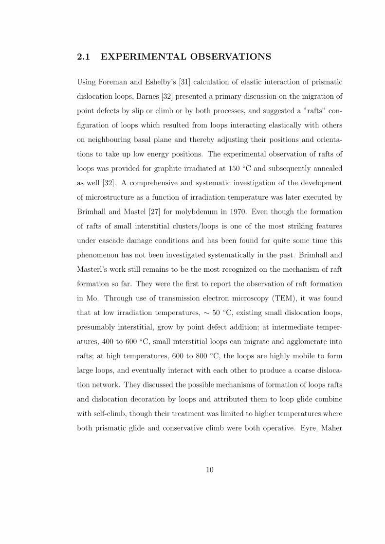
<1 1 1>
Figure 2.1: Idealized representation of an side view of prismatic edge dislocation
loops comprising a raft
Brimhall and Mastel [27] assumed that prismatic gliding of loops did not
occur at 323 K. However, recent molecular dynamics simulations have demon-
strated that small SIA loops glide rapidly via correlated diffusion of SIAs in the
clusters/loops [20], and furthermore, Trinkaus et al. [30] have shown that the dec-
oration of dislocation and formation of rafts are attributed to the one-dimensional
glide of SIA clusters to a great extent. An idealized configuration for a raft [27]
was also proposed with using the elastic calculations by Foreman and Eshelby
[31]. The edge-on representation of the configuration for this idealized raft is
shown in figure 2.1. Elastic analysis shows that loops lying at 42.4 with respect
to one another render a minimum interaction energy and form a stable configu-
ration. It was believed that rafts form by loops having identical Burgers vectors
gliding together as a result of the elastic interaction between the loops, but be-
ing prevented from complete coalescence by the limiting process of self climb
[29]. Since then more subsequent experimental observation of raft formation in
Mo and TZM (Mo-0.5Ti-0.1Zr) have been reported [34, 29, 35, 36, 37, 38]. The
11
Nasr Ghoniem
Pencil
Nasr Ghoniem
Pencil
Nasr Ghoniem
Pencil
Nasr Ghoniem
Pencil
Nasr Ghoniem
Pencil

formation of rafts of interstitial loops in the monocrystalline Mo was observed
occurring at a relatively low dose level of 5.4 × 10⁻³ dpa [38]. The segregation
of the microstructure into rafts of loops and isolated loops eventually leads to a
very heterogeneous microstructure at a dose level of 0.16 dpa. Eldrup and his
co-workers [9] investigated the difference in defect accumulation behavior, mainly
concerned about void nucleation and growth, between fcc Cu and bcc Fe under
neutron irradiation to fluences in the range of 10−4 to 0.8 dpa. TEM observa-
tions show that the density of SIA clusters both in Fe and Cu first increases with
dose. At doses higher than ' 0.01 dpa, the clusters begin to segregate and form
rafts of SIA clusters. The formation of the rafts-like structures is significantly
more efficient in bcc Fe than in fcc Cu. A TEM photograph of formation of rafts
of loops in Fe irradiated to a dose of 0.72 dpa was presented, the engineering
stress-strain curve by tensile test for the iron specimen irradiated to 0.72 dpa
exhibited a strong yield drop as well. In their experimental observations on void
formations in nickel 270 irradiated from 1 × 10¹⁸ to 1.5 × 10²² neutrons/cm2 at
various temperatures, Stiegler and Bloom [28] also reported rafts of small, perfect
dislocation loops, which they presumed as interstitial, were dispersed throughout
the specimens. Most experimental results suggest that a raft is made up of a
bunch of clusters of small interstitial loops, all having the same Burgers vector,
the raft as a whole having a clear < 111 > habit plane identical to the Burgers
vector of the loops. The size and distribution of rafts are heavily depended on
the material purity, irradiation temperature and irradiation dose, and the size
spectrum may range from ∼100 A to more than 1000 A [27, 29].
In many microstructural studies of neutron irradiated metals and alloys seg-
regation of small dislocation loops of SIA type is often observed in the vicinity of
grow-in dislocations in form of a ‘Cottrell-like’ atmosphere [39]. Figure 2.2 shows
the structure of a coarse dislocation network with a high concentration of small
12
Nasr Ghoniem
Pencil
Nasr Ghoniem
Pencil
Nasr Ghoniem
Pencil
Nasr Ghoniem
Pencil
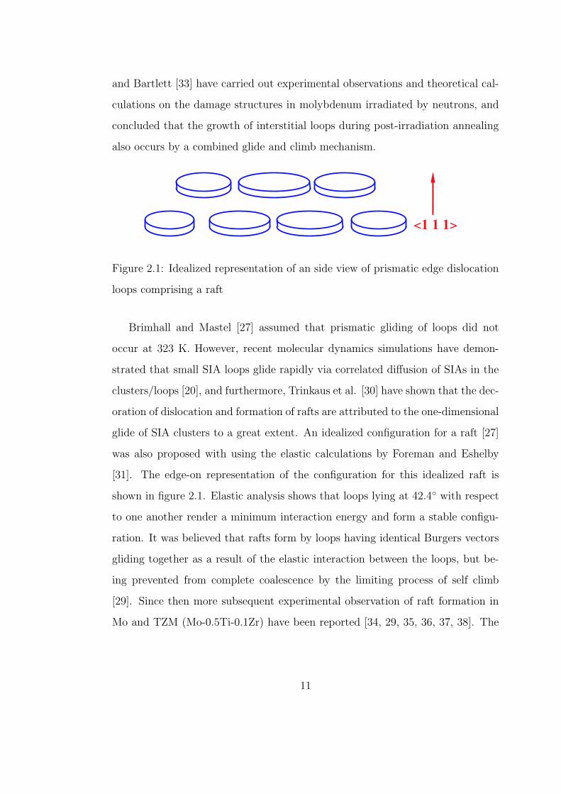
Figure 2.2: Dislocation structure in Nickel 270 irradiated to a fluence of 3.2×10¹⁹
neutron/cm2 [28].
loops located on or near the dislocation lines in Nickel 270 irradiated to a fluence
of 3.2 × 10¹⁹ neutrons/cm2 [28]. The phenomenon of decoration of dislocations
by small interstitial loops under cascade damage conditions have been observed
in a wide range of metals and alloys, for instance, pure nickel irradiated with 14
MeV neutrons at 300 K [40] and 560 K [41], Ni−2 at.% Cu and Ni−2 at.% Ge
alloys irradiated with 14 MeV neutrons at 563K [41], pure copper and copper
alloys irradiated with 14 MeV neutrons at 473 K [42], molybdenum irradiated
at 500 oC to a fluence of 5.7 ×10¹⁹ neutrons/cm2[27], and pure single crystal of
molybdenum irradiated with fission neutrons to a dose level of 1.6× 10⁻¹ dpa at
320 K [38].
13
2.2 THEORETICAL ANALYSIS ON MECHANISMS OF
DISLOCATION DECORATION AND RADIATION
HARDENING
Being associated with post-irradiation deformation behavior and post-deformation
microstructures, properties of clusters of vacancies and SIAs have received consid-
erable attentions because of their significant effects on microstructure evolutions.
The escalation of understanding the production, migration, and characters of
the SIA clusters has lead to the development of dislocation- and production-bias
[43] theories in terms of defect production and reaction kinetics to explain long-
term damage accumulation and microstructure evolution in irradiated materials,
in particular the heterogeneous and segregated features of microstructure under
cascade damage conditions. The production of stable SIA clusters in cascades
in combination with the decay of vacancy clusters at void swelling temperature
provides a remarkable driving force for void swelling, which has been called ‘pro-
duction bias’, on the condition that a considerably large number of stable SIA
clusters were annihilated preferentially at extend sinks such as dislocations, grain
boundaries and surfaces.
Of particular interest here is the already-mentioned microstructure features
of the formation of rafts of small dislocation loops and the decoration of disloca-
tion sources by loops. The available evidences on dislocation decoration could be
dated back as early as the discovery of raft formation (see Section 2.1), but it is
rather limited and scattered in literatures. No attempt was made to systemati-
cally study the phenomenon of dislocation decoration until Trinkaus, Singh and
Foreman [30] took the first leap on the mechanisms for decoration of dislocations
by small SIA loops. One earlier mechanism, which was suggested by Makin[44]
14
Nasr Ghoniem
Pencil
Nasr Ghoniem
Pencil
Nasr Ghoniem
Pencil
Nasr Ghoniem
Pencil
Nasr Ghoniem
Pencil
Nasr Ghoniem
Pencil
Nasr Ghoniem
Pencil
Nasr Ghoniem
Pencil
Nasr Ghoniem
Pencil
Nasr Ghoniem
Pencil
Nasr Ghoniem
Pencil
Nasr Ghoniem
Pencil
Nasr Ghoniem
Pencil
Nasr Ghoniem
Pencil
Nasr Ghoniem
Pencil
Nasr Ghoniem
Pencil
Nasr Ghoniem
Pencil
Nasr Ghoniem
Pencil
Nasr Ghoniem
Pencil
Nasr Ghoniem
Pencil
Nasr Ghoniem
Pencil
Nasr Ghoniem
Pencil
Nasr Ghoniem
Pencil
Nasr Ghoniem
Pencil
Nasr Ghoniem
Pencil
Nasr Ghoniem
Pencil
Nasr Ghoniem
Pencil
Nasr Ghoniem
Pencil
Nasr Ghoniem
Pencil
Nasr Ghoniem
Pencil
Nasr Ghoniem
Pencil
Nasr Ghoniem
Pencil
Nasr Ghoniem
Pencil
Nasr Ghoniem
Pencil
Nasr Ghoniem
Pencil

that the decoration of a dislocation by loops might result from the sweeping of
glissile SIA loops during the motion of the dislocation, was first ruled out by
examining the fact that the accumulation of SIAs near the dislocation contin-
ues even when the dislocations are locked. Calculation also shows that strain
enhanced clustering of single three-dimensionally migrating SIAs is unlikely to
produce the observed decoration phenomena, so is metastable one-dimensionally
migrating crowdion. The model proposed by Trinkaus et al.[30] concludes that
the trapping and accumulation of glissile SIA loops in terms of one-dimensional
motion is the dominant mechanism corresponding to the occurrence of dislocation
decoration and raft formation. A concept of stand-off distance is introduced such
that SIA clusters approaching the dislocation within the range of the stand-off dis-
tance get absorbed into the dislocation by spontaneously Burgers vector changes
or climb and the loop accumulation can take place only outside this region[12].
Based on the analysis of experimental measurements of plastic deformation in
metals irradiated with fission neutron, in conjunction with microstructure fea-
ture of dislocation decoration, Singh et al.[12] proposed the so-called ‘cascade-
induced source hardening’(CISH) model to explain the characteristic features in
the deformation behavior of metals and alloys under cascade damage conditions
such as the increase of the upper yield stress without dislocation generation and
followed by a yield drop and plastic instability. In the model, it is postulated
that a dislocation decorated with interstitial loops is confined by the surrounding
atmosphere of interstitial loops and unable to move as supposed until the ap-
plied resolved stress reaches a high level so that the dislocation can be released
from cluster atmospheres in the vicinity of the dislocation glide plane. The CISH
model was used to estimate the stress necessary to unlock trapped dislocations
from the atmosphere of loops surrounding them, so that these detrapped dislo-
cations can operate as dislocation sources. The increase in the critical resolved
15
Nasr Ghoniem
Pencil
Nasr Ghoniem
Pencil
Nasr Ghoniem
Pencil
Nasr Ghoniem
Pencil
Nasr Ghoniem
Pencil
Nasr Ghoniem
Pencil
Nasr Ghoniem
Pencil
Nasr Ghoniem
Pencil
Nasr Ghoniem
Pencil
Nasr Ghoniem
Pencil
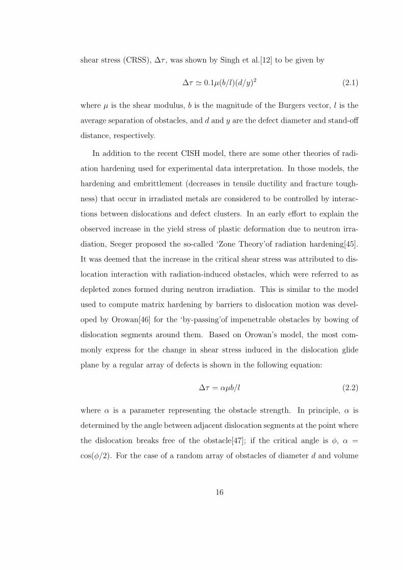
shear stress (CRSS), ∆τ , was shown by Singh et al.[12] to be given by
∆τ ' 0.1µ(b/l)(d/y)2 (2.1)
where µ is the shear modulus, b is the magnitude of the Burgers vector, l is the
average separation of obstacles, and d and y are the defect diameter and stand-off
distance, respectively.
In addition to the recent CISH model, there are some other theories of radi-
ation hardening used for experimental data interpretation. In those models, the
hardening and embrittlement (decreases in tensile ductility and fracture tough-
ness) that occur in irradiated metals are considered to be controlled by interac-
tions between dislocations and defect clusters. In an early effort to explain the
observed increase in the yield stress of plastic deformation due to neutron irra-
diation, Seeger proposed the so-called ‘Zone Theory’of radiation hardening[45].
It was deemed that the increase in the critical shear stress was attributed to dis-
location interaction with radiation-induced obstacles, which were referred to as
depleted zones formed during neutron irradiation. This is similar to the model
used to compute matrix hardening by barriers to dislocation motion was devel-
oped by Orowan[46] for the ‘by-passing’of impenetrable obstacles by bowing of
dislocation segments around them. Based on Orowan’s model, the most com-
monly express for the change in shear stress induced in the dislocation glide
plane by a regular array of defects is shown in the following equation:
∆τ = αµb/l (2.2)
where α is a parameter representing the obstacle strength. In principle, α is
determined by the angle between adjacent dislocation segments at the point where
the dislocation breaks free of the obstacle[47]; if the critical angle is φ, α =
cos(φ/2). For the case of a random array of obstacles of diameter d and volume
16
Nasr Ghoniem
Pencil
Nasr Ghoniem
Pencil
Nasr Ghoniem
Pencil
Nasr Ghoniem
Pencil
Nasr Ghoniem
Pencil
Nasr Ghoniem
Pencil
Nasr Ghoniem
Pencil
Nasr Ghoniem
Pencil
Nasr Ghoniem
Pencil
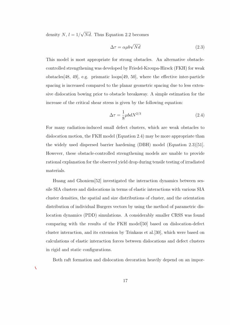
density N , l = 1/√
Nd. Thus Equation 2.2 becomes
∆τ = αµb√
Nd (2.3)
This model is most appropriate for strong obstacles. An alternative obstacle-
controlled strengthening was developed by Friedel-Kroupa-Hirsck (FKH) for weak
obstacles[48, 49], e.g. prismatic loops[49, 50], where the effective inter-particle
spacing is increased compared to the planar geometric spacing due to less exten-
sive dislocation bowing prior to obstacle breakaway. A simple estimation for the
increase of the critical shear stress is given by the following equation:
∆τ =1
8µbdN 2/3 (2.4)
For many radiation-induced small defect clusters, which are weak obstacles to
dislocation motion, the FKH model (Equation 2.4) may be more appropriate than
the widely used dispersed barrier hardening (DBH) model (Equation 2.3)[51].
However, these obstacle-controlled strengthening models are unable to provide
rational explanation for the observed yield drop during tensile testing of irradiated
materials.
Huang and Ghoniem[52] investigated the interaction dynamics between ses-
sile SIA clusters and dislocations in terms of elastic interactions with various SIA
cluster densities, the spatial and size distributions of cluster, and the orientation
distribution of individual Burgers vectors by using the method of parametric dis-
location dynamics (PDD) simulations. A considerably smaller CRSS was found
comparing with the results of the FKH model[50] based on dislocation-defect
cluster interaction, and its extension by Trinkaus et al.[30], which were based on
calculations of elastic interaction forces between dislocations and defect clusters
in rigid and static configurations.
Both raft formation and dislocation decoration heavily depend on an impor-
17
Nasr Ghoniem
Pencil
Nasr Ghoniem
Pencil
Nasr Ghoniem
Pencil
tant process, namely the production and migration of SIA clusters. Theoretically,
there are two main mechanisms which could result in the formation and growth
of interstitial loops: (1) the acquiring single SIA one at a time, and (2) the mi-
gration and aggregation of interstitial clusters. In most of the studied cases, the
first mechanism is concluded to play an insignificant role in terms of the fact that
the coexistence and simultaneous growth of vacancy and interstitial clusters[32].
If the first mechanism dominate the growth of clusters, it is necessary that an
interstitial loop mainly acquires interstitial atoms and rejects vacancies. The
efficiency of the growth process is predicably to be much lower than when the
second mechanism of loops migration are involved. Barnes[32] presented a illus-
trative discussion on the direction of migration, magnitude of the driving force,
and migration distance by considering two interacting simple prismatic edge dis-
location loops in aluminium. In reality the situation is much more complex than
in the two-interacting-loops case. When it is considered that the vacancy and
interstitial loops each have all the possible Burgers vectors, are not simple edge
dislocations, have various sizes, and in addition the interactions are not between
two loops but with all those nearby, the situation becomes overwhelmingly com-
plex. On the other hand, these atomic-scale cluster processes such as migration,
agglomeration, recombination etc., are difficult to observe in situ. The difficulties
encountered in the studies by experimental and analytical meanings make large
scale numerical simulations a practical and necessary option in investigating the
mechanisms of formation of rafts and dislocation decoration in neutron irradiated
materials.
18
Nasr Ghoniem
Pencil
Nasr Ghoniem
Pencil
Nasr Ghoniem
Pencil
Nasr Ghoniem
Pencil
Nasr Ghoniem
Pencil
Nasr Ghoniem
Pencil
Nasr Ghoniem
Pencil
Nasr Ghoniem
Pencil
Nasr Ghoniem
Pencil
Nasr Ghoniem
Pencil
Nasr Ghoniem
Pencil
Nasr Ghoniem
Pencil
Nasr Ghoniem
Pencil
Nasr Ghoniem
Pencil
Nasr Ghoniem
Pencil
Nasr Ghoniem
Pencil
Nasr Ghoniem
Pencil

CHAPTER 3
REVIEW OF KINETIC MONTE CARLO
METHOD
3.1 INTRODUCTION
In the study of radiation damage, MD simulations using semi-empirical embedded-
atom method (EAM) interatomic potentials have played a very important role in
understanding the details of defect production in displacement cascades, and in
helping to study the dynamics of point defect and defect cluster diffusion. Com-
prehensive reviews of recent development in MD simulations of radiation damage
have been given by Diaz de la Rubia [53] and Osetsky et al.[54]. Radiation
damage, however, includes a vast range of irradiation effects, such as production
and diffusion of point defects, and their interaction with other microstructure
features, which take place over time and length scales that span many orders
of magnitude. From a simulation perspective, although MD techniques can be
used to study the structure and the initial evolution of the damage, the compu-
tational time becomes prohibitive beyond the first few nanoseconds, even with
recent impressive advances in computers and algorithms. To overcome these
limitations, a way of connecting the MD simulation results to other simulation
methods such as rate theory (for example [55], [56] and [23]) or Kinetic Monte
Carlo simulations (for example [57], [58] and [59]) is required. In particular, KMC
19
Nasr Ghoniem
Pencil
Nasr Ghoniem
Pencil
Nasr Ghoniem
Pencil
Nasr Ghoniem
Pencil
Nasr Ghoniem
Pencil
Nasr Ghoniem
Pencil
Nasr Ghoniem
Pencil
Nasr Ghoniem
Pencil
Nasr Ghoniem
Pencil
Nasr Ghoniem
Pencil
simulations appear very promising because they provide the ability to perform
atomic-level simulations of the defect kinetics and microstructure evolution over
relevant length and time scales.
The Monte Carlo (MC) method refers to any stochastic techniques which
investigate problems by sampling from random numbers and using probability
statistics. It is generally believed that the widespread use of Monte Carlo con-
cept began with the Metropolis algorithm in the calculation for a rigid-sphere
system [60]. The MC method is simply a statistical method for solving determin-
istic or probabilistic problems. It is a physics experiment carried out numerically.
This technique can be readily used to study equilibrium properties of a system
of atoms. Since the kinetic path of microstructure evolution is physically mean-
ingless in this scheme, it is not suitable for treating defect distribution process in
radiation damage.
This chapter gives a detailed account of the Kinetic Monte Carlo (KMC)
method which is suitable for simulating kinetic evolution process. The n-fold
way algorithm [61] is first introduced which is believed to be the earliest form
of the current KMC concept. A formal KMC procedure specifically designed for
simulating cascade-induced damage evolution in this thesis is next described.
3.2 THE N-FOLD WAY ALGORITHM
In Metropolis MC methods we decide whether to accept a move by considering
the energy difference between the states. In KMC methods we use rates that de-
pend on the energy barrier between the states. The term “Kinetic Monte Carlo”
was initiated by Horia Metiu, Yan-Ten Lu and Zhenyu Zhang in a 1992 Science
paper [62]. The paper first pointed out the demands on atomic level control of
20
Nasr Ghoniem
Pencil
Nasr Ghoniem
Pencil
Nasr Ghoniem
Pencil
Nasr Ghoniem
Pencil
Nasr Ghoniem
Pencil
Nasr Ghoniem
Pencil
Nasr Ghoniem
Pencil
Nasr Ghoniem
Pencil
Nasr Ghoniem
Pencil
Nasr Ghoniem
Pencil
Nasr Ghoniem
Pencil
Nasr Ghoniem
Pencil
Nasr Ghoniem
Pencil
Nasr Ghoniem
Pencil
modern electronic and photonic devices and the importance of in situ STM obser-
vations of small atomic “clusters” to a theorist who wants to understand growth
and segregation; it then elaborated upon the usefulness of KMC simulations in
reproducing these experimental observations. The basic feature of their model
was to move atoms site-to-site on a square lattice terrace. They postulated rates
for all of the elementary processes involved, such as the site-to-site jumps, the
jumps to leave or join a step or an existing adsorbate cluster, and so forth. The
atoms were deposited on the surface and moved from site to site with a frequency
proportional to the rate of the respective move: if the rate constant of the i-th
kinetic process was ri, the largest rate was chosen as a reference and denoted rr.
The probability Pi = ri/rr was then used in a MC program as the probability
that the atom performed a jump i. The work used Voter’s transition state theory
[63] to monitor the simulation time. The essence through the references can be
traced to Bortz, Kalow, and Lebowitz’s n-fold way algorithm [61, 64, 65].
The n-fold way idea was created to replace the standard MC algorithm in
generating new configurations in simulating Ising spin systems. In or near the
equilibrium state, the standard MC scheme using a Boltzmann kinetic factor,
exp(-∆E/kT ), where ∆E is the system energy change, k is the Boltzmann con-
stant and T the absolute temperature, becomes very inefficient since the Boltz-
mann factor is usually very small in comparison with a random number over the
interval [0, 1] [61]. On the other hand, the n-fold way chooses a spin site from
the entire ensemble based upon its probability of flipping. Once a site was se-
lected, the flipping was guaranteed and could be immediately performed. The
n-fold way also provided a new simulation time concept. At each flip, the time
was incremented by a stochastic variable, ∆t, whose expectation value is pro-
portional to Q−1 (where Q is the number of spins times the average probability
that an attempt will produce a flip for a given configuration). Mathematically,
21
Nasr Ghoniem
Pencil
Nasr Ghoniem
Pencil
Nasr Ghoniem
Pencil
Nasr Ghoniem
Pencil
Nasr Ghoniem
Pencil
Nasr Ghoniem
Pencil
Nasr Ghoniem
Pencil
∆t = −(τ/Q) ln ξ, where ξ is a random fraction and τ a system dependent time.
This choice reflects properly the distribution of time intervals between flips for a
reasonable physical model. The cumulative time thus summed is approximately
proportional to real time. The n-fold way reduced computation time by an order
of magnitude or more for many applications [61]. A similar concept was used in
Voter’s 1987 transition state theory [63].
3.3 KINETIC MONTE CARLO METHOD
Molecular dynamics is probably the most accurate atomistic simulation tech-
nique. However, due to the fact that it simulates all the lattice atoms and, most
importantly, that it uses an almost constant time step on the order of femtosec-
onds (10−15 s), it cannot simulate the timescales involved in typical technological
processing steps (seconds to hours). The kinetic Monte Carlo method, on the
contrary, is an event-driven technique, i.e., simulates events at random with prob-
abilities according to the corresponding event rates. In this way it self-adjusts
the timestep as the simulation proceeds, depending on the fastest event present
at that time.
If Arrhenius-like relationship is assumed to describe the diffusional processes
of clusters, the jump frequency (or the probability per unit time) for a possible
jump of a cluster, i, to take place is given by:
ri = ω0 exp(− Ei
kBT) (3.1)
where ω0 is the pre-exponential factor of the defect cluster, kB the Boltzmann
constant, Ei the ‘effective’ activation energy for jumps of the cluster, and T is the
absolute temperature. Although the values of Ei for interstitials and vacancies
are well known from experiments, the values of Ei for small clusters and glissile
22
Nasr Ghoniem
Pencil
Nasr Ghoniem
Pencil
Nasr Ghoniem
Pencil
Nasr Ghoniem
Pencil
Nasr Ghoniem
Pencil
Nasr Ghoniem
Pencil
Nasr Ghoniem
Pencil
dislocation loops and of ν0 for all kinds of defects have not been obtained exper-
imentally. In the present work, we will use results of MD calculations for these
values.
In many applications of the MC method, such as the equilibration of atomic
positions in a defected crystal, the space of possible configurations that the system
can assume is continuous. Therefore, there exists (in theory) an infinite number of
new configurations available to the system at any MC step. However, since we are
simulating defects in a volume of finite size which evolves according to a finite
set of physical or mechanical mechanisms, the number of new configurations
available at any MC step is finite and enumerable. This configuration space is
discrete. In other words, at each MC step, we can determine all of the potential
changes that the system can possibly undergo. Therefore, instead of attempting
a random change to the system at each simulation step and then accepting or
rejecting that change based on some criterion, we choose and execute one change
from the list of all possible changes at each simulation step. The choice is made
based on the relative rates at which each change can occur (i.e., the probability
of choosing one particular reaction instead of another is proportional to the rate
at which the reaction occurs relative to the rates of the other reactions).
Thus the microstructure evolution of the cascade-induced defect clusters is
accomplished by a KMC procedure in which one reaction is executed at one
site during each time step. The first step in KMC simulations is to tabulate
the rate at which an event (i) will take place anywhere in the system, ri. The
probability of selecting an event is simply equal to the rate at which the event
occurs relative to the sum of all possible event rates. Once an event is chosen,
the system is changed appropriately, and the list of events that can occur at the
next KMC step is updated. Therefore, at each KMC step, one event denoted by
23
Nasr Ghoniem
Pencil
Nasr Ghoniem
Pencil
Nasr Ghoniem
Pencil
m is randomly selected from all possible M events, as follows:
m−1∑
i=0
ri
M∑
i=0
ri
< ξ1 <
m∑
i=0
ri
M∑
i=0
ri
(3.2)
where ri is the rate at which event i occurs (r0 = 0) and ξ1 is a random number
uniformly distributed in the range [0, 1]. The way in which the M events are
labeled (i.e., by specifying which events correspond to i = 1, 2, 3, . . . ,m, . . . ,M)
is arbitrary. After an event is chosen and executed, the total number of possible
events, M , and the sequence in which the events are labeled, will change.
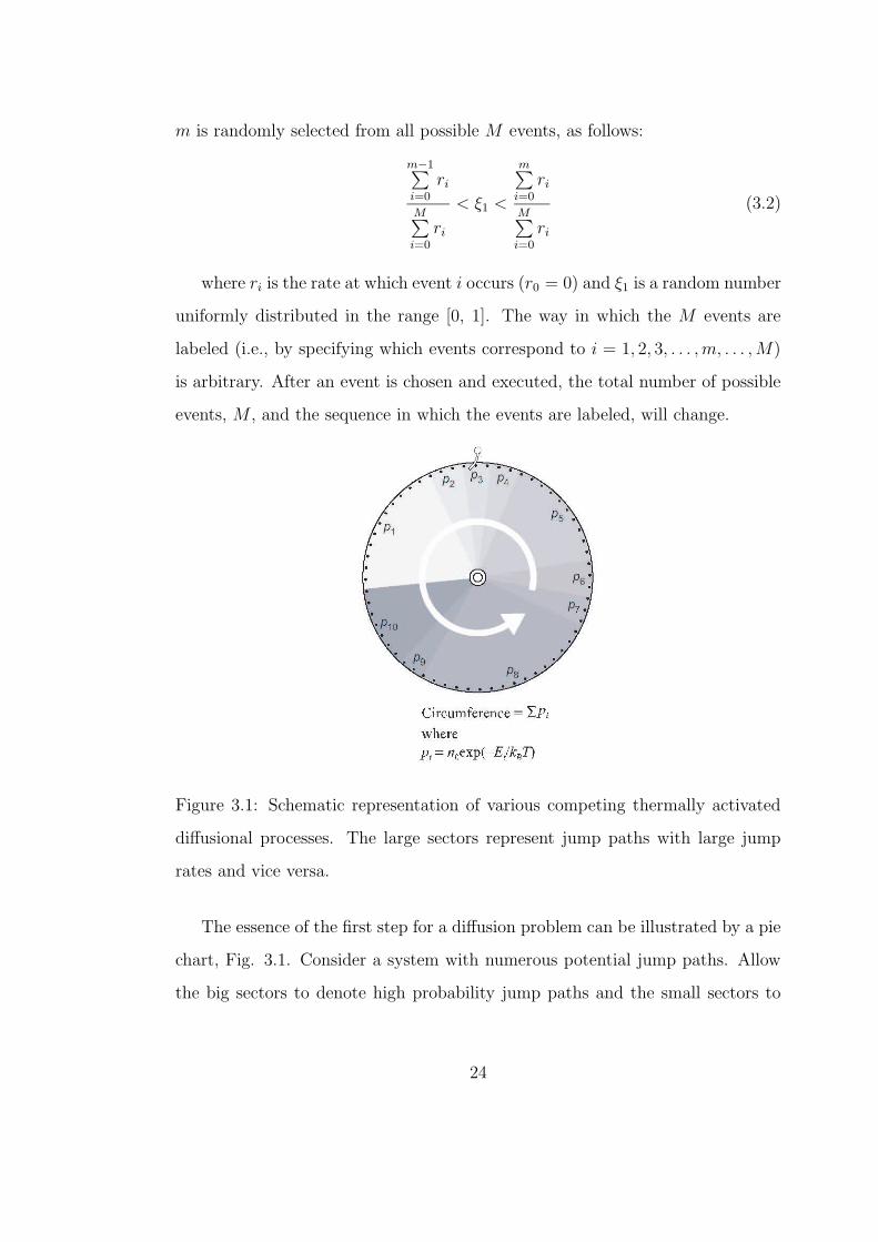
Figure 3.1: Schematic representation of various competing thermally activated
diffusional processes. The large sectors represent jump paths with large jump
rates and vice versa.
The essence of the first step for a diffusion problem can be illustrated by a pie
chart, Fig. 3.1. Consider a system with numerous potential jump paths. Allow
the big sectors to denote high probability jump paths and the small sectors to
24
Nasr Ghoniem
Pencil
Nasr Ghoniem
Pencil
Nasr Ghoniem
Pencil
denote low probability paths. To faithfully execute the KMC process, any one
of them, no matter it is a high or low probability jump, should have a chance to
be selected. This can be accomplished by allowing every point on the perimeter
of the pie-chart to have an equal chance to be selected. This automatically takes
into account the weighting process. For the present work, since the number of
mobile defects is not very large, we used the simple linear search algorithm.
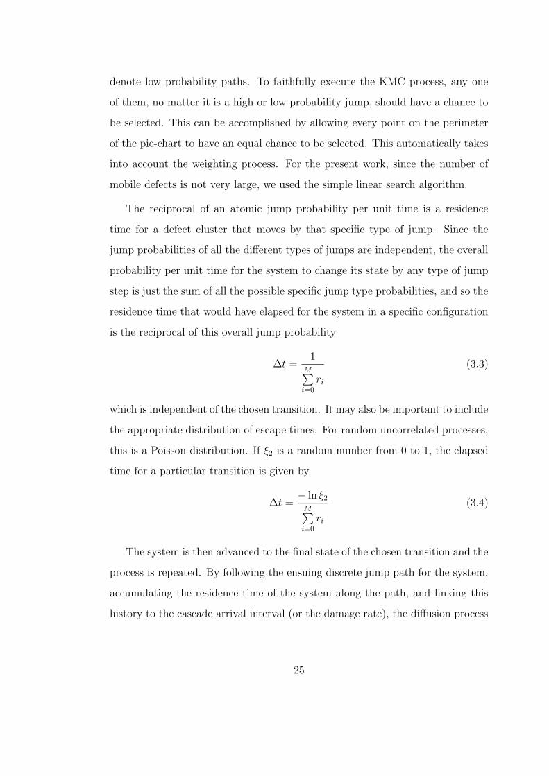
The reciprocal of an atomic jump probability per unit time is a residence
time for a defect cluster that moves by that specific type of jump. Since the
jump probabilities of all the different types of jumps are independent, the overall
probability per unit time for the system to change its state by any type of jump
step is just the sum of all the possible specific jump type probabilities, and so the
residence time that would have elapsed for the system in a specific configuration
is the reciprocal of this overall jump probability
∆t =1
M∑
i=0
ri
(3.3)
which is independent of the chosen transition. It may also be important to include
the appropriate distribution of escape times. For random uncorrelated processes,
this is a Poisson distribution. If ξ2 is a random number from 0 to 1, the elapsed
time for a particular transition is given by
∆t =− ln ξ2
M∑
i=0
ri
(3.4)
The system is then advanced to the final state of the chosen transition and the
process is repeated. By following the ensuing discrete jump path for the system,
accumulating the residence time of the system along the path, and linking this
history to the cascade arrival interval (or the damage rate), the diffusion process
25
Nasr Ghoniem
Pencil
Nasr Ghoniem
Pencil
Nasr Ghoniem
Pencil
Nasr Ghoniem
Pencil
Nasr Ghoniem
Pencil
Nasr Ghoniem
Pencil
can be realistically simulated. The expression for ∆t in Eqn. 3.4 is rigorous[61],
and a derivation is also provided by Battaile[66].
26
CHAPTER 4
ELASTIC REPRESENTATION OF DEFECTS
4.1 KRONER’S DESCRIPTION OF POINT DEFECTS
BY FORCE MULTIPOLES
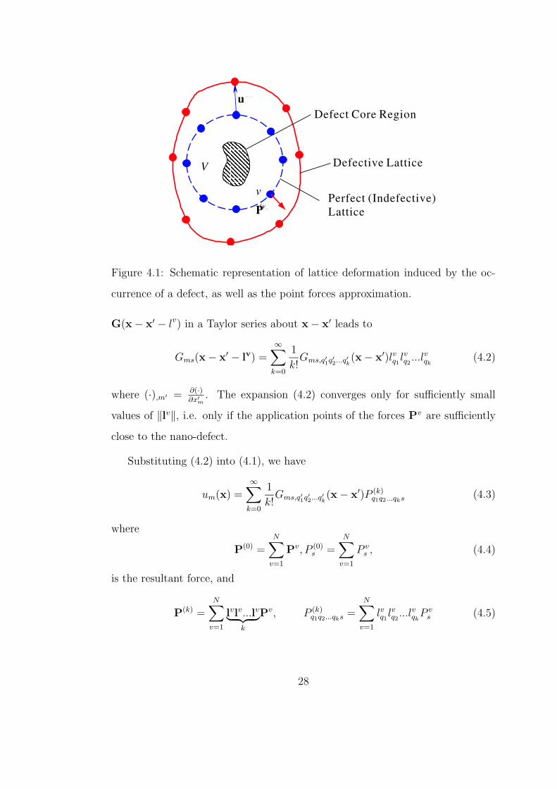
Although the interaction between atomic-size defects requires extensive MD or
even abinitio calculations, the theory of elasticity can be utilized to simplify such
calculations. Defect-defect interaction does not generally result in significant local
deformation, and hence linear elasticity is expected to give accurate results. This
approach has been successfully used to describe static defect-defect interactions
[50, 67, 68, 69]. Following Kroner [70] and Teodosiu [71], nano-scale defects exert
forces on the atoms in theirs vicinity, which are different from those acting on
these atoms in a perfect lattice. Let Pv denote the additional forces exerted by
a nano-defect centred at x′ on the atom situated at x′ + lv. According to the
definition of Green’s function, the force system Pv generates in an infinite elastic
medium the displacement field (see Figure 4.1)
um(x) =N∑
v=1
Gms(x − x′ − lv)P vs (4.1)
where G is Green’s tensor function of the elastic medium, while N is the number
of atoms on which extra forces are exerted. Theoretically, N = ∞, but, as Pv
decays very rapidly when ‖lv‖ → ∞, it is usually sufficient to take into account
only the forces employed on the first and second nearest neighbors. Expanding
27
Nasr Ghoniem
Pencil
Nasr Ghoniem
Pencil
Nasr Ghoniem
Pencil
Nasr Ghoniem
Pencil
Nasr Ghoniem
Pencil
Nasr Ghoniem
Pencil
Nasr Ghoniem
Pencil
Nasr Ghoniem
Pencil
Nasr Ghoniem
Pencil
Nasr Ghoniem
Pencil
Nasr Ghoniem
Pencil
Nasr Ghoniem
Pencil
Nasr Ghoniem
Pencil
Nasr Ghoniem
Pencil
Nasr Ghoniem
Pencil
Nasr Ghoniem
Pencil
Nasr Ghoniem
Pencil
Nasr Ghoniem
Pencil
Nasr Ghoniem
Pencil
Nasr Ghoniem
Pencil
Nasr Ghoniem
Pencil
Nasr Ghoniem
Pencil
Nasr Ghoniem
Pencil
Nasr Ghoniem
Pencil
Nasr Ghoniem
Pencil
Nasr Ghoniem
Pencil
Nasr Ghoniem
Pencil
u m
v
P(v)
V
Perfect (Indefective)Lattice
Defect Core Region
Defective Lattice
Figure 4.1: Schematic representation of lattice deformation induced by the oc-
currence of a defect, as well as the point forces approximation.
G(x − x′ − lv) in a Taylor series about x − x′ leads to
Gms(x − x′ − lv) =∞∑
k=0
1
k!Gms,q′1q′2...q′
k(x − x′)lvq1
lvq2...lvqk
(4.2)
where (·),m′ = ∂(·)∂x′
m
. The expansion (4.2) converges only for sufficiently small
values of ‖lv‖, i.e. only if the application points of the forces Pv are sufficiently
close to the nano-defect.
Substituting (4.2) into (4.1), we have
um(x) =∞∑
k=0
1
k!Gms,q′1q′2...q′
k(x − x′)P (k)
q1q2...qks (4.3)
where
P(0) =N∑
v=1
Pv, P (0)s =
N∑
v=1
P vs , (4.4)
is the resultant force, and
P(k) =N∑
v=1
lvlv...lv︸ ︷︷ ︸
k
Pv, P (k)q1q2...qks =
N∑
v=1
lvq1lvq2
...lvqkP v
s (4.5)
28
is the multipolar moment of the k-th order, k = 1, 2, ..., of the system of additional
forces Pv exerted by the nano-defect on its surroundings. In particular, the
following tensors are called dipole moment, quadrupole moment and octopole
moment, respectively,
P(1) =N∑
v=1
lvPv, P(2) =N∑
v=1
lvlvPv, P(3) =N∑
v=1
lvlvlvPv, (4.6)
Applying the differential operator
1
k!P (k)
q1q2...qks
∂k
∂x′
q1∂x′
q2...∂x′
qk
(4.7)
to the equilibrium equation of a unit point force
CijmnGms,jn(x − x′) + δisδ(x − x′) = 0 (4.8)
where Cijmn is the elastic tensor and δis is the Kronecker δ, and comparing the
results with (4.3), we can see that the action of a nano-defect on the elastic
medium is equivalent to that of a body force field, which consists of force dipoles,
quadrupoles, octopoles, etc. applied at the center of the defect, namely:
fi(x) =∞∑
k=0
P(k)q1q2...qkiδ,q′1q′2...q′
k(x − x′) (4.9)
where
P (k)q1q2...qks =
1
k!P (k)
q1q2...qks (4.10)
the strengths of the multipolar forces, fi(x), being completely determined through
(4.10) by the multipolar moments associated with the nano-defect [71]. It should
be noted that the resultant force and couple exerted by a nano-defect on its
surroundings are zero. Thus, the equilibrium condition implies
N∑
v=1
Pv = 0,N∑
v=1
lv × Pv = 0 (4.11)
29
The last relation may be rewritten as
N∑
v=1
εknslvnP v
s = εknsP(1)ns = 0 (4.12)
where εkns is so called permutation tensor. The dipole moment P(1) must be a
symmetric tensor, and conditions (4.11) are equivalent to:
P(0) = 0, P(1) = (P(1))T (4.13)
Introducing (4.13) into (4.3), we obtain:
um(x) =∞∑
k=0
(−1)k
k!Gms,q1q2...qk
(x − x′)P (k)q1q2...qks (4.14)
Equation (4.14) shows that the elastic field produced by a nano-defect in an
infinite elastic medium is completely determined by the multipolar moments P(k),
k = 1, 2, ..., provided that Green’s tensor functions of the medium are known.
For an isotropic material this function is
Gms(x − x′) =1
16πµ(1 − ν)
[
δms(3 − 4ν)1
r+
(xm − x′
m)(xs − x′
s)
r3
]
(4.15)
where r = ‖x − x′‖. By substituting (4.15) into (4.14), we see that u(x) is of the
order O(r−2) as r → ∞, in agreement with the results obtained in modeling point
defects by rigid spherical inclusions in an infinite isotropic medium. Assuming
that the elastic medium is isotropic, we obtain from (4.15) that
∂Gms(x − x′)
∂xs
= − 1 − 2ν
8πµ(1 − ν)
xm − x′
m
r3(4.16)
As already mentioned, the elastic field of a nano-defect is characterized by its
multipolar moments. The main procedure for evaluating these quantities is to
solve the equation system (4.14) with the displacement field u(x) acquired by MD
simulation. As a rough approximation, we can only consider the force system Pv
exerted on the first nearest neighbors and the first term in the Taylor expansion
(4.14).
30
Nasr Ghoniem
Pencil
Nasr Ghoniem
Pencil
Nasr Ghoniem
Pencil
4.1.0.1 The elastic interaction between nano-defects
In this section we will study the elastic interaction between nano-defects which
are simulated by force multipoles acting in an infinite elastic medium. It should
be noted that this description of nano-defects provides a good approximation
only if the separation distance between defects is large enough. Otherwise, a
semi-discrete or fully atomic model of the interacting defects must be adopted.
The elastic interaction energy between a nano-defect located at x and an
elastic displacement field u is given, according to elastic theory, by the work
done against the forces Pv exerted by the point defect on the neighboring atoms,
i.e.
Φint = −N∑
v=1
Pv · u(x + lv) (4.17)
By expanding u(x + lv) in a Taylor series around x, we obtain
um(x + lv) =∞∑
n=0
1
n!um,j1j2...jn
(x)lvj1j2...jn
= um(x) + um,i(x)lvi +1
2!um,ij(x)lvi l
vj +
1
3!um,ijk(x)lvi l
vj l
vk + ... (4.18)
Substituting this expansion into (4.17) and considering (4.4), (4.5), and (4.13)
yields
Φint = −∞∑
n=0
1
n!um,j1j2...jn
(x)P(n)j1j2...jnm
= −[
P(1)im um,i(x) +
1
2!P
(2)ijmum,ij(x) +
1
3!P
(3)ijkmum,ijk(x) + ...
]
(4.19)
In a homogeneous strain field we have um,i(x) = const. and (4.19) reduces to
Φint = −P(1)im um,i = −P
(1)im Eim (4.20)
i.e. only the dipole moments contribute to the interaction energy. Returning to
the general case, we recall that the force employed on the nano-defects by the
31
Nasr Ghoniem
Pencil
elastic state which generates the displacement field u is
F = −gradxΦint (4.21)
Hence, by taking into account (4.19), we have
Fs = −∂Φint
∂xs
=∞∑
n=1
1
n!um,j1j2...jns(x)P
(n)j1j2...jnm
= P(1)im um,is(x) +
1
2!P
(2)ijmum,ijs(x) +
1
3!P
(3)ijkmum,ijks(x) + ... (4.22)
We can now easily derive the elastic interaction energy of two point defects situ-
ated at points x and x′ in an infinite elastic medium and having the multipolar
moments P(1),P(2), ..., and respectively P(1), P(2), ..., by substituting the expres-
sion (4.14) of the displacement field produced by one of the defects into (4.19).
The results reads
Φint = −∞∑
n=0
1
n!P
(n)j1j2...jnm
∞∑
k=1
(−1)k
k!P (k)
q1q2...qksGms,q1q2...qkj1j2...jn(x − x′) (4.23)
Since G(x−x′) = O(r−1) as r = ‖x − x′‖ → ∞, we see that the first three terms
of the expression (4.23) decrease as r−3, r−4,and r−5, respectively, for sufficiently
large values of the separation distance r between the defects.
4.2 ELASTIC INTERACTION BETWEEN DEFECTS
The interaction between the atoms can be obtained from an (approximate) so-
lution of the Schrodinger equation [72] describing electrons, or from a potential
energy function determined in some empirical way (for example, MD simulations
[73]), but they are computationally expensive. Most often, it is sufficient to treat
the interactions between atoms in terms of the analysis of elastic interactions.
However, so far, all KMC computer simulations for microstructure evolution un-
der irradiation have not considered the influence of the internal and applied stress
32
Nasr Ghoniem
Pencil
fields on defect motion (for example [74, 57, 26, 75]). We propose here a KMC
simulation, where the elastic interactions between SIA/vacancy clusters them-
selves, SIA and vacancy clusters, and SIA/vacancy clusters and dislocations are
explicitly accounted for.
Recently, a new computational method has been developed [76, 77] for ac-
curate evaluation of the elastic field of dislocation aggregates in complex 3-D
geometry. The method extends the capabilities of 2-D estimates of elastic field
variables in realistic material geometry, and enables calculations of displacements,
strain, stress, interaction and self-energies, and finally, the work associated with
rotation and translation of defect clusters. In the following sections, the numer-
ical method developed by Ghoniem [76] and Ghoniem and Sun [77] to examine
the mechanisms of interaction between small defect clusters and slip dislocation
loops is introduced, followed by the calculation needed to develop an specific
elastic interaction energies between defects for use in this thesis.
For the specific case of parametric dislocation loop representation, the elastic
field tensors (strain εij and stress σij) of a dislocation loop are given by line
integrals over the dislocation loop line vector as follows [78]
εij =1
8π
∮
C
[
−1
2(εjklbiR,l + εiklbjR,l − εiklblR,j − εjklblR,i),pp
+1
1 − νεkmnbnR,mij
]
dlk (4.24)
where R = ‖R‖ = ‖x − x‖.
Since the linear stress-strain relationship is σij = 2µεij + λεrrδij, the stress
tensor is also obtained as a line integral, of the general form
σij =µbn
4π
∮
C
[1
2R,mpp(εjmndli′ + εimndlj′) +
m
m − 1εkmn(R,ijm − δijR,ppm)dlk′
]
(4.25)
33
where µ and λ are the Lame constants (µ = shear modulus, and λ/2(λ+µ) = ν =
Poisson’s ratio), bn are the components of Burgers vector, R,ijk are derivatives
of the radius vector norm between a loop point at x and a field point x, dli′
are differential line elements along the dislocation line vector, and εijk is the
permutation tensor. Ghoniem [76] developed explicit forms for the integrals of
general parametric dislocation loops. An efficient numerical integration scheme
has also been developed for calculations of the stress field, as a fast summation
by Ghoniem and Sun [77]. Their results read
σij =µ
4π
Nloop∑
γ=1
Ns∑
β=1
Qmax∑
α=1
bnwα
[1
2R,mpp(εjmnxi,u + εimnxj,u)
+1
1 − νεkmn(R,ijm − δijR,ppm)xk,u
]
(4.26)
where Nloop, Ns, and Qmax are the total number of loops, segments, and Gaussian
quadrature, respectively. wα is the quadrature weight, and xj,u are parametric
derivatives of the Cartesian components of the vector x, which describes the loop
geometry. The interaction energy of two dislocation loops over the volume V of
the material is expressed by
EI =
∫
V
σ(1)ij ε
(2)ij dV (4.27)
in which σ(1)ij is the stress arising from the first dislocation and ε
(2)ij the strain
originating in the other. For the present study, if the second loop (defect cluster)
is assumed to be infinitesimal, the interaction energy can be simplified to [50]
EI = δA(2)n(2)i σ
(1)ij b
(2)j (4.28)
where n(2)i is the unit normal vector to the defect cluster habit plane of area δA(2).
By substituting Eqn. 4.26 into Eqn. 4.28 with Nloop = 1, we can readily compute
the interaction energy of the cluster, designated with the superscript (2), and the
34
slip loop, of Burgers vector b(1)n , as
EI =µδA(2)n
(2)i b
(2)j
4π
Ns∑
β=1
Qmax∑
α=1
b(1)n wα
[1
2R,mpp(εjmnxi,u + εimnxj,u)
+1
1 − νεkmn(R,ijm − δijR,ppm)xk,u (4.29)
In the above equation, we assume that the stress tensor of the grown-in (slip)
dislocation loop is constant over the cross-section of a small point-defect cluster.
In case we treat one single vacancy or interstitial atom as a center of dilatation,
the interaction energy simplifies to
EI = −4
9πr3
0ε(2)ii σ
(1)jj (4.30)
where ε(2)ii is the dilatation and r0 is the effective radius of a point defect. The
above equation does not reveal dependence of the interaction energy surface on
the orientation of the cluster Burgers vector, unlike Eqn. 4.29.
Kroupa [50] obtained the formulae for the displacement and stress field around
an infinitesimal dislocation loop by extending the derivation used by Eshelby [79].
The stress tensor σij is
σij =
− k0µ
4π(1 − ν)R3
[3(1 − 2ν)
R2bkρknlρl + (4ν − 1)bknk
]
δij
+(1 − 2ν)(binj + nibj) +3ν
R2[bkρk(niρj + ρinj) + nkρk(biρj + ρibj)]
+
[3(1 − 2ν)
R2bknk −
15
R4bkρknlρl
]
ρiρj
δA (4.31)
where ρi = xi − xi is the radius vector between the loop center at point x and a
field point at x. n is the the unit normal vector to the defect cluster habit plane
of area δA, and b Burgers vector. By applying Eqn. 4.28, the elastic interaction
energy between two infinitesimal loops can also be obtained.
35
4.3 REPRESENTATION OF NANO-DEFECTS BY FORCE
DIPOLES
4.3.0.2 Representation of nano-defects by force dipoles
Point defects are lattice imperfections having all dimensions of the order of one or
more atomic spacing. The point defect may be a vacant sites in the atomic lattice,
called a vacancy, a foreign atom replacing one atom of the lattice, called a substi-
tutional atoms, or a atom situated between the normal sites of the lattice, called
an interstitial atom. Sometimes, two or more point defects can build charac-
teristic arrangements which are thermodynamically stable to form a point defect
cluster. Our interest will be particularly focus on these nano-scalling point defect
clusters. The collection of point defects produces viscous effects at a macroscopic
scale, which are of great importance for many processes taking place in crystals.
Moreover, the interaction of a nano-defect with other crystal defects is mostly of
elastic nature. We will try to develop elastic models of nano-defects and methods
for calculating the elastic interaction of a defect with other defects.
Firstly, let us consider now in detail the physical significance of the partial
derivatives of first order of G(x). We can obviously write
Gij,k(x) = limh→0
1
hGij(x) − Gij(x − hek) (4.32)
Consequently, the elastic state associated to the displacement field
ui(x) = Gij,k(x) (4.33)
is the limiting value as h → 0 of a sum of two elastic states: the first corresponds
to the concentrated force ej/h acting at the origin; the second corresponds to a
concentrated load −ej/h acting at the point with position vector hek. A straight-
forward calculation shows that the resultant of the stress vectors acting on any
36
Nasr Ghoniem
Pencil
Nasr Ghoniem
Pencil
Nasr Ghoniem
Pencil
Nasr Ghoniem
Pencil
Nasr Ghoniem
Pencil
Nasr Ghoniem
Pencil
Nasr Ghoniem
Pencil
Nasr Ghoniem
Pencil
Nasr Ghoniem
Pencil
Nasr Ghoniem
Pencil
Nasr Ghoniem
Pencil
Nasr Ghoniem
Pencil
Nasr Ghoniem
Pencil
Nasr Ghoniem
Pencil
sphere Ση with radius η and center at the origin is zero, while their resulting cou-
ple equals −ek × ej. Following the terminology introduced by Love, we say that
the elastic field corresponding to the displacement (4.33) is produced by a unit
double force, which is statically equivalent to a directed concentrated couple or
to 0 according as j 6= k or j = k. In the latter case we say that the singularity at
the origin is a unit double force without moment. The elastic state corresponding
to the displacement field
ui(x) = Gij,j(x) (4.34)
which is produced by three mutually orthogonal unit double forces without mo-
ment acting at the origin, is called a center of compression, whereas the elastic
state corresponding to the opposite of (4.34) is called a center of dilatation. It
has been shown that the effects of a vacancy or an interstitial atom can be ap-
proximated by a spherical compression center of dilatation center.
In view of formula (4.33), we propose here that a nano-defect of arbitrary
geometric shape can be described by a collection of double forces. Specifically,
we have
ui(x) = Gij,k(x − x′)fkj(x′) (4.35)
where fjk is a second order tensor of which the three diagonal components rep-
resents three mutually orthogonal force dipoles without moment, and the rest
non-diagonal components are force dipoles with moment along ej × ek. It should
be noted that the resultant force and couple of these components consisting fjk
should be equal to zero. The condition of zero resultant force can be achieved
in terms of the definition of force dipole. Then, the condition of zero net force
couple implies that the tensor fjk must be a symmetric tensor, i.e.
fkj(x′) = fT
kj(x′) (4.36)
37
Nasr Ghoniem
Pencil
Nasr Ghoniem
Pencil
Nasr Ghoniem
Pencil
Nasr Ghoniem
Pencil
Suppose that we have already got the displacement of each and every lattice atom
somehow, say by Molecular Dynamics simulation or experiments. We then can
use the least square method to determine the point force dipolar system, i.e. fjk,
which are unknown and exerted on the center of the defect to characterize the
elastic field of the defect. If the real displacement field is denoted by u(x), we
define the error function
Π =N∑
m=1
‖u(x) − u(x)‖2 =N∑
m=1
[u(x) − u(x)] [u(x) − u(x)] (4.37)
where N is the number of points whose displacements are already known and we
used to calculated the error. According to the method of least squares, the best
fitting value of fjk has the property that
Π = aminimum, (4.38)
i.e.∂Π
∂fjk
= 0 (4.39)
By solving these six equations we would be able to define a force dipole tensor
that can approximately describe the elastic field induced by the existence of the
defect.
As far as the interaction energy between two nano-defects is concerned, it can
be readily shown that
Φint = −f · gradu(x) = −fijuj,i(x) (4.40)
where fij is the force dipole used to represent the nano-defect at x, and u(x) is
the displacement field induced by the defect at x′, which can also be described by
a force dipole tensor f . By substituting the expression (4.35) of the displacement
field produced by one of the defects into (4.40), it results
Φint = −fij flkGjk,li(x − x′) (4.41)
38
Nasr Ghoniem
Pencil
Nasr Ghoniem
Pencil
4.4 APPLICATIONS
For simplicity, in the following we will choose the geometric center of the nano-
defect as origin, i.e., x′ = 0.
4.4.1 VACANCY
Gij =1
16πµ(1 − ν)r
[
δij(3 − 4ν) +xixj
r2
]
(4.42)
Gij,k =1
16πµ(1 − ν)r3
[
−(3 − 4ν)δijxk + δikxj + xiδjk −3xixjxk
r2
]
(4.43)
ui = Gij,kfkj
=1
16πµ(1 − ν)r3
[
−(3 − 4ν)fikxk + fijxj + xifjj −3xixjxk
r2fkj
]
(4.44)
At r = r0, the displacement field u is known as
ur(r0) = Cr−2, uφ = uθ = 0 (4.45)
where C is an arbitrary constant. Substituting (4.44) and (4.45) into (4.39) yields
the equations designed to determine the values of fij. Actually, the derived equa-
tions are not completely mutually independent, and some other relations have
to be introduced to help with solving equations. Due to the spherical symmetry
of the deformation, only the components of dipolar forces whose indices occur
in pairs of equal numbers are non-zero, i.e. f12 = f13 = f23 = 0. By solving
equations, we obtain
f11 = f22 = f33 = 8(ν − 1)Cπµ
1 − 2ν= −4πC(λ + 2µ) (4.46)
The field (4.46) represents three mutually orthogonal force dipoles without mo-
ment, having equal intensities, and acting at the centre of the point defect, and
39
Nasr Ghoniem
Pencil
Nasr Ghoniem
Pencil
such distribution of concentrated loads is called a spherical dilatation centre. The
values in (4.46) are exactly the same as the solutions given by the elastic theory
with the assumption of point defect as rigid spherical inclusion.
4.4.2 INFINITESIMAL PRISMATIC DISLOCATION LOOP
Let us assume the loop is at the origin of the coordinate system on the x1x2
plane (n1 = n2 = 0, n3 = 1) and suppose displacement field is given by Kroupa’s
formula. Namely, the displacements of a pure prismatic infinitesimal dislocation
loop with an area δA, b1 = b2 = 0, b3 = b are as follows:
u1 =K
6
x1
r3
[
−(1 − 2ν) +3x2
3
r2
]
u2 =K
6
x2
r3
[
−(1 − 2ν) +3x2
3
r2
]
(4.47)
u3 =K
6
x3
r3
[
1 − 2ν +3x2
3
r2
]
where
r =√
x21 + x2
2 + x23 (4.48)
K = − 3b3
4π(1 − ν)δA (4.49)
The displacements at (x1, 0, 0), (0, x2, 0), and (0, 0, x3) are
u(1)1 = −K
6
1
x21
(1 − 2ν), u(1)2 = u
(1)3 = 0,
u(2)2 = −K
6
1
x22
(1 − 2ν), u(2)1 = u
(2)3 = 0, (4.50)
u(3)3 =
K
3
1
x23
(2 − ν), u(3)1 = u
(3)2 = 0,
respectively, However, the displacements at these three points given by (4.44) are
u(1)1 =
1
16πµ(1 − ν)x21
[−4(1 − ν)f11 + f22 + f33] , u(1)2 = − (1 − 2ν)f12
8πµ(1 − ν)x21
,
40
Nasr Ghoniem
Pencil
Nasr Ghoniem
Pencil
Nasr Ghoniem
Pencil
u(1)3 = − (1 − 2ν)f13
8πµ(1 − ν)x21
u(2)1 = − (1 − 2ν)f12
8πµ(1 − ν)x22
, u(2)2 =
1
16πµ(1 − ν)x22
[−4(1 − ν)f22 + f11 + f33] ,
u(2)3 = − (1 − 2ν)f23
8πµ(1 − ν)x22
(4.51)
u(3)1 = − (1 − 2ν)f13
8πµ(1 − ν)x23
, u(3)2 = − (1 − 2ν)f23
8πµ(1 − ν)x23
,
u(3)3 =
1
16πµ(1 − ν)x23
[−4(1 − ν)f33 + f11 + f22]
Substituting (4.50) and (4.51) into (4.37) results
Π =3∑
m=1
3∑
i=1
[
u(m)i − u
(m)i
]2
(4.52)
By solving the equations given by (4.39) we obtain
f12 = f13 = f23 = 0, f11 = f22 = −λb3δA, f33 = −(λ + 2µ)b3 (4.53)
It can shown that (4.53) are exactly the same as those given by Kroupa. It
implies that the displacement field produced by force dipoles (4.53), as well as
the strain and stress field will be the same as the results derived by Kroupa.
41
Nasr Ghoniem
Pencil
Nasr Ghoniem
Pencil
Nasr Ghoniem
Pencil
Nasr Ghoniem
Pencil
Nasr Ghoniem
Pencil
CHAPTER 5
DEVELOPMENT OF NEW
COMPUTATIONAL MODELS FOR
RADIATION DAMAGE ACCUMULATION
AND SEGREGATION
5.1 INTRODUCTION
Under cascade-producing irradiation, defect production and subsequent defect
accumulation are strongly influenced by features of the initial cascade damage
event. The temporal and spatial inhomogeneities of cascade damage, as well as
details of damage that manifest themselves on the atomic scale, make it neces-
sary to develop atomic-scale models as the basis for understanding the effects of
cascade production on microstructure evolution and mechanical property changes
in irradiated materials. The ability to correlate and extrapolate irradiation test
data on fusion materials hinges on understanding radiation damage at this scale,
as well as understanding its influence on behavior at the macroscopic scale.
Advances in atomistic descriptions of cascade events by molecular dynamics
(MD) simulations in the past decade, coupled with experimental information,
have resulted in the identification of cluster formation directly in cascades, and
the subsequent behavior of those clusters, as key elements affecting the evolution
42
of the microstructure. Stochastic annealing simulation provides a bridge between
the atomistic and macroscopic scales that enables the direct effects of cascade
production on the microstructure to be investigated. The work reported on here
is the next step beyond the application of stochastic annealing simulations to the
local short-term annealing stage of individual cascades, which has been reported
elsewhere [57, 58, 80]. We present here on the simulation of the kinetics of damage
accumulation under low doses of cascade-producing irradiation in iron at room
temperature.
5.2 A KINETIC MONTE CARLO APPROACH TO RA-
DIATION DAMAGE EVOLUTION WITH ELASTIC
INTERACTION CONSIDERATION
The jump frequency (or the probability per unit time) for a possible jump of a
SIA cluster, i, to take place is given by Equation 3.1. We first tabulate the rate
at which an event (i) will take place anywhere in the system, ri. The probability
of selecting an event is equal to the rate at which the event occurs relative to the
sum of all possible event rates. Once an event is selected, the system is changed
correspondingly, and the list of events that can occur at the next KMC step is
updated. Therefore, at each KMC step, one event denoted by m is randomly
selected from all possible M events. The reciprocal of an atomic jump frequency
is a residence time for a defect cluster that moves by that specific type of jump.
Since the jump probabilities of all different types of jumps are independent, the
overall probability density for the system to change its state by any type of jump
step is just the sum of all possible specific jump probabilities. Therefore, the
residence time that would have elapsed for the system in a specific configuration
43
Nasr Ghoniem
Pencil
Nasr Ghoniem
Pencil
Nasr Ghoniem
Pencil
Nasr Ghoniem
Pencil
Nasr Ghoniem
Pencil
Nasr Ghoniem
Pencil
Nasr Ghoniem
Pencil
Nasr Ghoniem
Pencil
Nasr Ghoniem
Pencil
is the reciprocal of the overall jump probability rate ∆t = 1/M∑
i=0
ri, which is
independent of the chosen transition. It may also be important to include the
appropriate distribution of escape times. For random uncorrelated processes, the
distribution of the time elapsing between events is the exponential distribution
if the process is a Poisson process. The elapsed time for a particular transition
is given by Equation 3.4. The system is then advanced to the final state of the
chosen transition and the process is repeated.
All KMC computer simulations for microstructure evolution under irradiation
have not yet considered the influence of the internal and applied stress fields on
the kinetics of mobile defects, for example in the ALSOME [80] or BIGMAC [26]
codes. In most realistic situations, however, interactions between dislocations
and point defects play a key role in determining the effects of radiation on me-
chanical properties. The present KMC method accounts for elastic interactions
amongst SIA clusters, nanovoids and dislocations. We explicitly incorporate here
the effects of elastic interactions between SIA and vacancy clusters themselves
(cluster-cluster type), and between defect clusters and dislocations (dislocation-
cluster type). SIA clusters are directly produced on the periphery of neutron
collision cascades, and they may contain from a few atoms up to tens of atoms
in the near vicinity of the cascade [15, 81]. According to the results of MD
simulations [73], the most stable configuration of SIA clusters is a set of 〈111〉crowdions.
In view of the availability of size-dependent cluster characteristics provided by
MD simulations, we simulated 〈111〉 type SIA clusters, consistent with published
MD simulations. Such clusters are extremely mobile, and migrate predominantly
along highly-packed crystallographic directions, with migration energies of less
than 0.1 eV [26, 15]. Small SIA clusters may also spontaneously change their
44
Nasr Ghoniem
Pencil
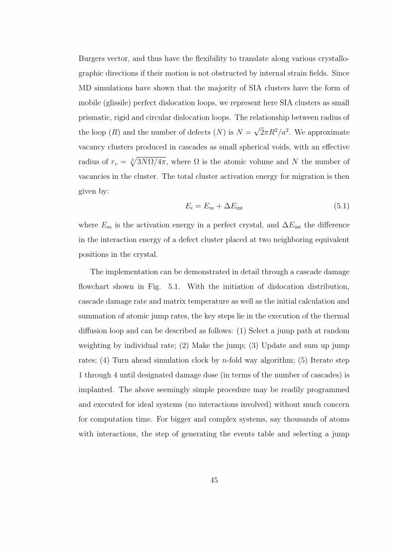
Burgers vector, and thus have the flexibility to translate along various crystallo-
graphic directions if their motion is not obstructed by internal strain fields. Since
MD simulations have shown that the majority of SIA clusters have the form of
mobile (glissile) perfect dislocation loops, we represent here SIA clusters as small
prismatic, rigid and circular dislocation loops. The relationship between radius of
the loop (R) and the number of defects (N) is N =√
2πR2/a2. We approximate
vacancy clusters produced in cascades as small spherical voids, with an effective
radius of rv = 3√
3NΩ/4π, where Ω is the atomic volume and N the number of
vacancies in the cluster. The total cluster activation energy for migration is then
given by:
Ei = Em + ∆Eint (5.1)
where Em is the activation energy in a perfect crystal, and ∆Eint the difference
in the interaction energy of a defect cluster placed at two neighboring equivalent
positions in the crystal.
The implementation can be demonstrated in detail through a cascade damage
flowchart shown in Fig. 5.1. With the initiation of dislocation distribution,
cascade damage rate and matrix temperature as well as the initial calculation and
summation of atomic jump rates, the key steps lie in the execution of the thermal
diffusion loop and can be described as follows: (1) Select a jump path at random
weighting by individual rate; (2) Make the jump; (3) Update and sum up jump
rates; (4) Turn ahead simulation clock by n-fold way algorithm; (5) Iterate step
1 through 4 until designated damage dose (in terms of the number of cascades) is
implanted. The above seemingly simple procedure may be readily programmed
and executed for ideal systems (no interactions involved) without much concern
for computation time. For bigger and complex systems, say thousands of atoms
with interactions, the step of generating the events table and selecting a jump
45
Nasr Ghoniem
Pencil
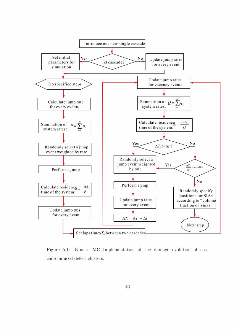
Introduce one new single cascade
1st cascade?
Set initial
parameters for
simulation
Update jump rates
for every event
Summation of
system rates:å
=
=N
i
ipP1
Randomly select a jump
event weighted by rate
Perform a jump
Update jump rates
for every event
Calculate residence
time of the system: Pt
xln-=D
Set laps timeDTc between two cascades
Update jump rates
for vacancy events
Summation of
system rates:å
=
=M
j
jqQ1
Calculate residence
time of the system: Qt
xln-=D
Randomly select a
jump event weighted
by rate
DTc > Dt ?
Perform a jump
Update jump rates
for every event
DTc = DTc - Dt
Randomly specify
positions for SIAs
according to “volume
fraction of sinks”
?#randc >Dt
Do specified steps
Calculate jump rate
for every eventpi
Next step
Yes No
Yes No
Yes
No
Figure 5.1: Kinetic MC Implementation of the damage evolution of cas-
cade-induced defect clusters.
46
path from a large number of jump paths can be a daunting task and very careful
programming is needed to obtain efficient execution. Otherwise, intrinsically fast
MC method (compared to MD) can be unreasonably slow.
5.3 MAIN MODEL FEATURES
The cascade-induced defect distribution process consists of several distinct steps,
introduction of defects associated with one high-energy displacement cascade,
interaction between defects resulting in instant (intracascade) recombination of
defects of opposite types and agglomeration of defects of the same type, diffusion
incorporated with interactions between dislocations, impurities and point defects
leading to defect annihilation at a sink, trapping of defects by impurities, deco-
ration slip dislocations with defect clusters. To simulate the defect distribution
process, all of the process should be incorporated. Although interaction may
not be important at a dilute defect density or very large apart distance and can
be approximated accordingly using ALSOME [57, 58, 74, 80, 82] or BIGMAC
[26, 75] code, in most practical situations the interactions between dislocations
and point defects play a key role in determining the effects of radiation on me-
chanical properties. This interaction effects must therefore be taken into account.
The methodology should also address the many diffusional pathways available.
It should also connect with the temperature and damage rate these control the
available time for microstructure evolution processes before the defect densities
reach a dynamic equilibrium state (saturated densities).
In last section the main idea of KMC scheme has been described. We present
here a computer simulation method which explicitly incorporates the effects of
the elastic interactions between SIA and vacancy clusters themselves (cluster-
cluster type), and between defect clusters and dislocations (dislocation-cluster
47
Nasr Ghoniem
Pencil
type). SIA clusters are directly produced on the periphery of neutron collision
cascades, and they may contain from a few atoms up to tens of atoms in the
near vicinity of the cascade [83]. Such clusters are extremely mobile, and migrate
predominantly along highly-packed crystallographic directions, with migration
energies of less than 0.1 eV [83, 26]. Small SIA clusters may also spontaneously
change their Burgers vector, and thus have the flexibility to translate along vari-
ous crystallographic directions if their motion is not obstructed by internal strain
fields. Since MD simulations have shown that the majority of SIA clusters have
the form of mobile (glissile) perfect dislocation loops, in this work, we represent
SIA clusters as small prismatic, rigid and circular dislocation loops. As for va-
cancies, small spherical voids are employed to approximate single vacancies and
vacancy clusters. The effective radius of void has been defined as
rv =3
√
3NΩ
4π(5.2)
where Ω is the atomic volume and N the number of defects in the cluster. The
temperature dependence of the jump frequency of defect clusters diffusion has
been given as 3.1. In our KMC simulation, the elastic interaction is incorpo-
rated. The influence of other defects and the external stress on one SIA or
vacancy cluster is given by the stress field σij. By applying the infinitesimal
dislocation loop approximation for SIA clusters , the work necessary to form the
loop characterized by normal n, Burgers vector b and area δA in the stress field
σij is SIA cluster interaction energy Eint, and is given by Eqn. 4.28. Similarly,
we have vacancy cluster interaction energy shown as Eqn. 4.30 where it need to
be noted that,
εjj =q
K=
GδV
πa30K
(5.3)
where 3K = 3λ + 2G called the volume modulus.
48
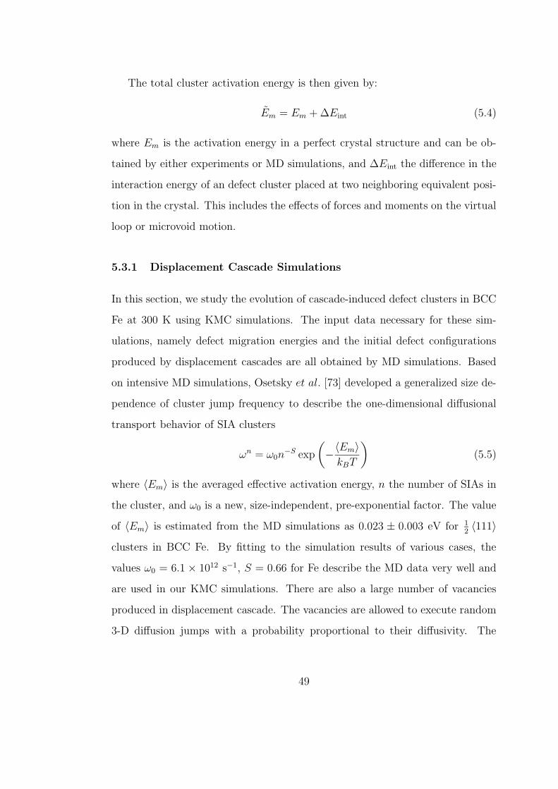
The total cluster activation energy is then given by:
Em = Em + ∆Eint (5.4)
where Em is the activation energy in a perfect crystal structure and can be ob-
tained by either experiments or MD simulations, and ∆Eint the difference in the
interaction energy of an defect cluster placed at two neighboring equivalent posi-
tion in the crystal. This includes the effects of forces and moments on the virtual
loop or microvoid motion.
5.3.1 Displacement Cascade Simulations
In this section, we study the evolution of cascade-induced defect clusters in BCC
Fe at 300 K using KMC simulations. The input data necessary for these sim-
ulations, namely defect migration energies and the initial defect configurations
produced by displacement cascades are all obtained by MD simulations. Based
on intensive MD simulations, Osetsky et al. [73] developed a generalized size de-
pendence of cluster jump frequency to describe the one-dimensional diffusional
transport behavior of SIA clusters
ωn = ω0n−S exp
(
−〈Em〉kBT
)
(5.5)
where 〈Em〉 is the averaged effective activation energy, n the number of SIAs in
the cluster, and ω0 is a new, size-independent, pre-exponential factor. The value
of 〈Em〉 is estimated from the MD simulations as 0.023 ± 0.003 eV for 12〈111〉
clusters in BCC Fe. By fitting to the simulation results of various cases, the
values ω0 = 6.1 × 10¹² s−1, S = 0.66 for Fe describe the MD data very well and
are used in our KMC simulations. There are also a large number of vacancies
produced in displacement cascade. The vacancies are allowed to execute random
3-D diffusion jumps with a probability proportional to their diffusivity. The
49
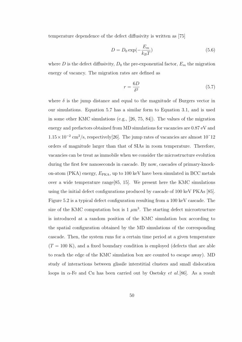
temperature dependence of the defect diffusivity is written as [75]
D = D0 exp(− Em
kBT) (5.6)
where D is the defect diffusivity, D0 the pre-exponential factor, Em the migration
energy of vacancy. The migration rates are defined as
r =6D
δ2(5.7)
where δ is the jump distance and equal to the magnitude of Burgers vector in
our simulations. Equation 5.7 has a similar form to Equation 3.1, and is used
in some other KMC simulations (e.g., [26, 75, 84]). The values of the migration
energy and prefactors obtained from MD simulations for vacancies are 0.87 eV and
1.15×10⁻² cm2/s, respectively[26]. The jump rates of vacancies are almost 10˜12
orders of magnitude larger than that of SIAs in room temperature. Therefore,
vacancies can be treat as immobile when we consider the microstructure evolution
during the first few nanoseconds in cascade. By now, cascades of primary-knock-
on-atom (PKA) energy, EPKA, up to 100 keV have been simulated in BCC metals
over a wide temperature range[85, 15]. We present here the KMC simulations
using the initial defect configurations produced by cascade of 100 keV PKAs [85].
Figure 5.2 is a typical defect configuration resulting from a 100 keV cascade. The
size of the KMC computation box is 1 µm3. The starting defect microstructure
is introduced at a random position of the KMC simulation box according to
the spatial configuration obtained by the MD simulations of the corresponding
cascade. Then, the system runs for a certain time period at a given temperature
(T = 100 K), and a fixed boundary condition is employed (defects that are able
to reach the edge of the KMC simulation box are counted to escape away). MD
study of interactions between glissile interstitial clusters and small dislocation
loops in α-Fe and Cu has been carried out by Osetsky et al.[86]. As a result
50
Nasr Ghoniem
Pencil
Nasr Ghoniem
Pencil
Nasr Ghoniem
Pencil
Nasr Ghoniem
Pencil
Nasr Ghoniem
Pencil
Nasr Ghoniem
Pencil
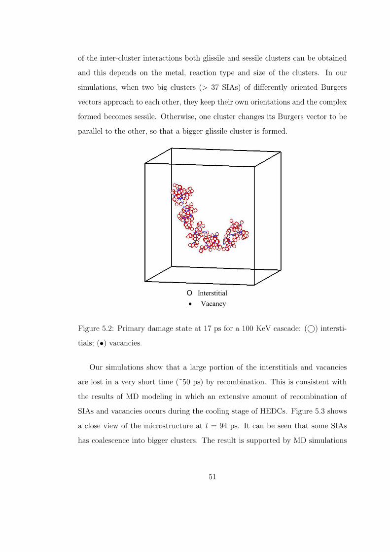
of the inter-cluster interactions both glissile and sessile clusters can be obtained
and this depends on the metal, reaction type and size of the clusters. In our
simulations, when two big clusters (> 37 SIAs) of differently oriented Burgers
vectors approach to each other, they keep their own orientations and the complex
formed becomes sessile. Otherwise, one cluster changes its Burgers vector to be
parallel to the other, so that a bigger glissile cluster is formed.
Figure 5.2: Primary damage state at 17 ps for a 100 KeV cascade: (©) intersti-
tials; (•) vacancies.
Our simulations show that a large portion of the interstitials and vacancies
are lost in a very short time (˜50 ps) by recombination. This is consistent with
the results of MD modeling in which an extensive amount of recombination of
SIAs and vacancies occurs during the cooling stage of HEDCs. Figure 5.3 shows
a close view of the microstructure at t = 94 ps. It can be seen that some SIAs
has coalescence into bigger clusters. The result is supported by MD simulations
51
Nasr Ghoniem
Pencil
Nasr Ghoniem
Pencil
Nasr Ghoniem
Pencil
Nasr Ghoniem
Pencil
Nasr Ghoniem
Pencil
in which one of the most significant findings is the occurrence of intracascade
clustering. Most of the recombination and clustering take place within 10 ns.
Most of the glissile interstitials and interstitial clusters escape away from the
cascade center within around 60 ns. The value of freely migrating defects(FMDs)
production efficiency η obtained by our KMC simulation is η ≈ 0.1 (i.e. 10%).
The cases of incorporating with internal dislocations are also studied. Since the
density of glissile SIAs is rather low (˜1018 m−3), no visible dislocation decorations
have been observed.
Cell Size = 1 m, T = 100 K282 SIA Clusters607 Vacancy ClustersTime = 94.37207 ps
m
Figure 5.3: A close view of the structure of one single cascade at t = 94 ps. Small
circular loops represent SIA clusters, and solid points represent vacancies.
52
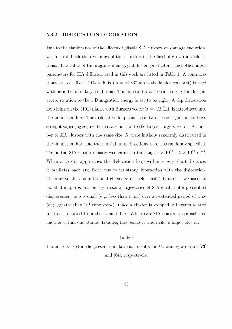
5.3.2 DISLOCATION DECORATION
Due to the significance of the effects of glissile SIA clusters on damage evolution,
we first establish the dynamics of their motion in the field of grown-in disloca-
tions. The value of the migration energy, diffusion pre-factors, and other input
parameters for SIA diffusion used in this work are listed in Table 1. A computa-
tional cell of 400a× 400a× 400a ( a = 0.2867 nm is the lattice constant) is used
with periodic boundary conditions. The ratio of the activation energy for Burgers
vector rotation to the 1-D migration energy is set to be eight. A slip dislocation
loop lying on the (101) plane, with Burgers vector b = a/2[111] is introduced into
the simulation box. The dislocation loop consists of two curved segments and two
straight super-jog segments that are normal to the loop’s Burgers vector. A num-
ber of SIA clusters with the same size, R, were initially randomly distributed in
the simulation box, and their initial jump directions were also randomly specified.
The initial SIA cluster density was varied in the range 5 × 10²² − 2 × 10²³ m−3.
When a cluster approaches the dislocation loop within a very short distance,
it oscillates back and forth due to its strong interaction with the dislocation.
To improve the computational efficiency of such ‘ fast ’ dynamics, we used an
‘adiabatic approximation’ by freezing trajectories of SIA clusters if a prescribed
displacement is too small (e.g. less than 1 nm) over an extended period of time
(e.g. greater than 104 time steps). Once a cluster is stopped, all events related
to it are removed from the event table. When two SIA clusters approach one
another within one atomic distance, they coalesce and make a larger cluster.
Table 1
Parameters used in the present simulations. Results for Em and ω0 are from [73]
and [84], respectively.
53
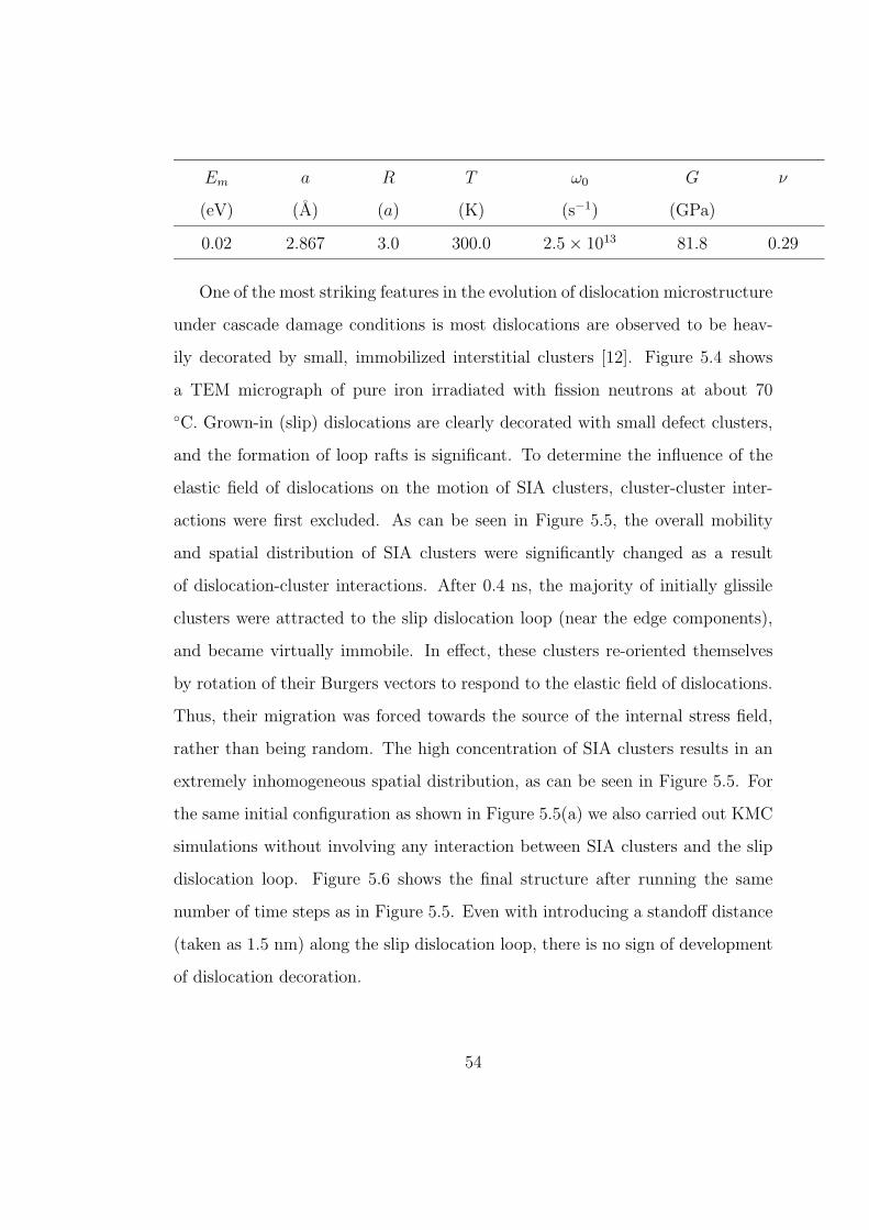
Em a R T ω0 G ν
(eV) (A) (a) (K) (s−1) (GPa)
0.02 2.867 3.0 300.0 2.5 × 10¹³ 81.8 0.29
One of the most striking features in the evolution of dislocation microstructure
under cascade damage conditions is most dislocations are observed to be heav-
ily decorated by small, immobilized interstitial clusters [12]. Figure 5.4 shows
a TEM micrograph of pure iron irradiated with fission neutrons at about 70
C. Grown-in (slip) dislocations are clearly decorated with small defect clusters,
and the formation of loop rafts is significant. To determine the influence of the
elastic field of dislocations on the motion of SIA clusters, cluster-cluster inter-
actions were first excluded. As can be seen in Figure 5.5, the overall mobility
and spatial distribution of SIA clusters were significantly changed as a result
of dislocation-cluster interactions. After 0.4 ns, the majority of initially glissile
clusters were attracted to the slip dislocation loop (near the edge components),
and became virtually immobile. In effect, these clusters re-oriented themselves
by rotation of their Burgers vectors to respond to the elastic field of dislocations.
Thus, their migration was forced towards the source of the internal stress field,
rather than being random. The high concentration of SIA clusters results in an
extremely inhomogeneous spatial distribution, as can be seen in Figure 5.5. For
the same initial configuration as shown in Figure 5.5(a) we also carried out KMC
simulations without involving any interaction between SIA clusters and the slip
dislocation loop. Figure 5.6 shows the final structure after running the same
number of time steps as in Figure 5.5. Even with introducing a standoff distance
(taken as 1.5 nm) along the slip dislocation loop, there is no sign of development
of dislocation decoration.
54
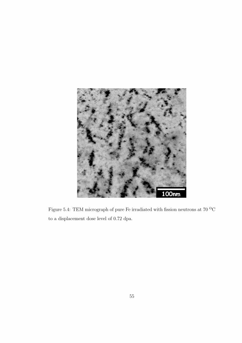
Figure 5.4: TEM micrograph of pure Fe irradiated with fission neutrons at 70 oC
to a displacement dose level of 0.72 dpa.
55
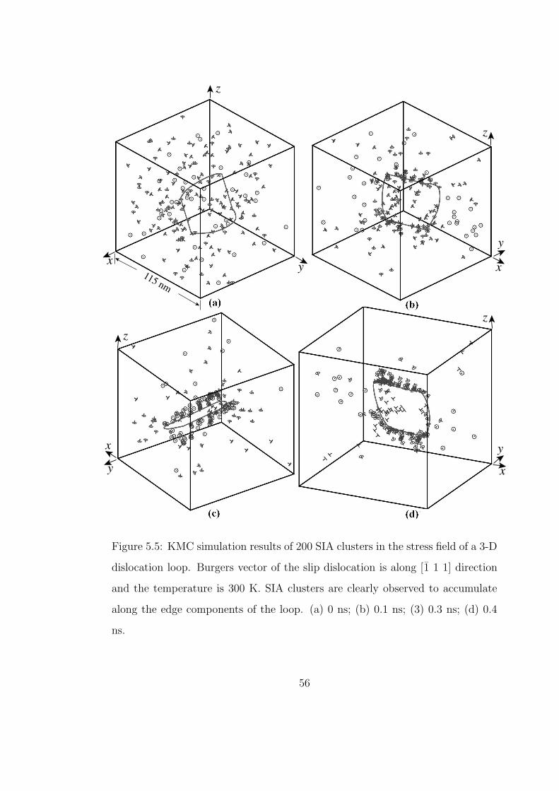
x
y
zz
x
x
y
y
y
x
z
z
115 nm
Figure 5.5: KMC simulation results of 200 SIA clusters in the stress field of a 3-D
dislocation loop. Burgers vector of the slip dislocation is along [1 1 1] direction
and the temperature is 300 K. SIA clusters are clearly observed to accumulate
along the edge components of the loop. (a) 0 ns; (b) 0.1 ns; (3) 0.3 ns; (d) 0.4
ns.
56
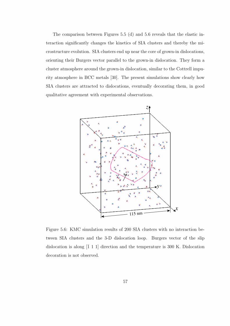
The comparison between Figures 5.5 (d) and 5.6 reveals that the elastic in-
teraction significantly changes the kinetics of SIA clusters and thereby the mi-
crostructure evolution. SIA clusters end up near the core of grown-in dislocations,
orienting their Burgers vector parallel to the grown-in dislocation. They form a
cluster atmosphere around the grown-in dislocation, similar to the Cottrell impu-
rity atmosphere in BCC metals [30]. The present simulations show clearly how
SIA clusters are attracted to dislocations, eventually decorating them, in good
qualitative agreement with experimental observations.
z
x
y
115 nm
Figure 5.6: KMC simulation results of 200 SIA clusters with no interaction be-
tween SIA clusters and the 3-D dislocation loop. Burgers vector of the slip
dislocation is along [1 1 1] direction and the temperature is 300 K. Dislocation
decoration is not observed.
57
5.3.3 PINNING AND SMALL RAFTS OF SMALL INTERSTITIAL
LOOPS
To investigate the influence of cluster-cluster interactions on their motion, the
grown-in dislocation was removed, and the elastic interaction between clusters
included in a new KMC simulation. Mutual elastic interactions in between clus-
ters was found to affect their distribution and motion drastically. Because of
mutual interaction, two clusters that are oriented along non-parallel crystallo-
graphic orientations will either coalesce forming a larger one, or rotate and pin
one another at a short distance and move jointly in the same direction. Once two
clusters are pinned together, they have less chance to change their orientation,
and therefore their motion becomes almost pure one-dimensional. As this pro-
cess proceeds, some additional clusters may be trapped into this pinned structure
by changing their Burgers vectors. This self-organizing mechanism eventually re-
sults in the occurrence of SIA rafts, which consist of small dislocation loops with
the same direction of motion. This feature has been experimentally observed for
some time [30].
It has to be noted that when the defect is big enough to behave as a perfect
dislocation loop it may not follow the mechanisms mentioned above. Instead,
dislocation loops may follow the rule of summation of Burgers vectors and form
sessile 〈100〉 loops. The formation and growth of 〈100〉 interstitial loops in bcc
iron have been confirmed by both experiments and MD simulations [?]. However,
the mechanism for the formation of 〈100〉 loops through interactions between
1/2〈111〉 loops seems more feasible at high temperature and high irradiation
dose. Considering the conditions for our simulations, namely low damage doses
and room temperature, the present investigation is focused on 〈111〉 interstitial
loops. The formation of 〈100〉 loops through the direct interaction of 1/2〈111〉
58
Nasr Ghoniem
Pencil
loops, as well as the effects of 〈100〉 loops have been excluded.
A simulation of cluster motion integrating the influence of the internal stress
field created by grown-in dislocations, as well as the clusters themselves was also
performed. Figure 5.7 shows a typical defect evolution time sequence for 200
SIA clusters at 300 K. The effects of internal dislocation fields, aided by cluster
mutual elastic interactions, rendered most of the clusters virtually immobile in
the vicinity of the slip dislocation. Continuation of the decoration process results
in the initiation of a ‘dislocation wall’. Similar simulations were performed for a
smaller cluster density (50 SIA clusters), and also at a higher temperature (600
K). The results indicate that the SIA cluster density seems to have a greater
influence on the transient time for decoration than temperature. At high tem-
peratures, the kinetics of dislocation decorations is faster as a result of increased
cluster jump rates. The simulations also show that the rafting structure occurs
more readily at lower temperatures.
It should be noted that we excluded absorption reactions between grown-
in dislocations and SIA clusters, since our major concern in the present work
is the segregation and agglomeration of defect clusters, as supported by direct
experimental observations. Except for a direct encounter between a glissile loop
and a dislocation, absorption of a loop by the dislocation requires a change in the
direction of motion of the loop, either by a thermally activated Burgers vector
change or by self-climb. Using MD simulations, Rodney and Martin investigated
the mechanisms of the absorption of small interstitial loops by an edge dislocation
in fcc nickel [87, 88]. It was shown that small interstitial clusters participating in
absorption reactions represent rather weak dispersed barriers and do not have an
impact on the yield drop phenomenon observed experimentally. It was also shown
that small interstitial loops may find their stable positions a few lattice planes
59
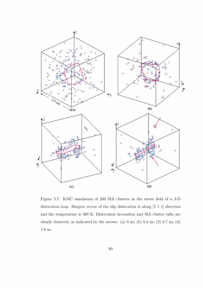
x x
z
z
y
y
x
x
zz
yy
115 nm
Figure 5.7: KMC simulation of 200 SIA clusters in the stress field of a 3-D
dislocation loop. Burgers vector of the slip dislocation is along [1 1 1] direction
and the temperature is 300 K. Dislocation decoration and SIA cluster rafts are
clearly observed, as indicated by the arrows. (a) 0 ns; (b) 0.4 ns; (3) 0.7 ns; (d)
1.0 ns.
60
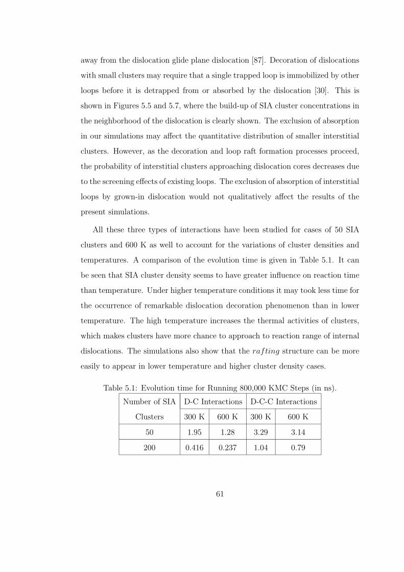
away from the dislocation glide plane dislocation [87]. Decoration of dislocations
with small clusters may require that a single trapped loop is immobilized by other
loops before it is detrapped from or absorbed by the dislocation [30]. This is
shown in Figures 5.5 and 5.7, where the build-up of SIA cluster concentrations in
the neighborhood of the dislocation is clearly shown. The exclusion of absorption
in our simulations may affect the quantitative distribution of smaller interstitial
clusters. However, as the decoration and loop raft formation processes proceed,
the probability of interstitial clusters approaching dislocation cores decreases due
to the screening effects of existing loops. The exclusion of absorption of interstitial
loops by grown-in dislocation would not qualitatively affect the results of the
present simulations.
All these three types of interactions have been studied for cases of 50 SIA
clusters and 600 K as well to account for the variations of cluster densities and
temperatures. A comparison of the evolution time is given in Table 5.1. It can
be seen that SIA cluster density seems to have greater influence on reaction time
than temperature. Under higher temperature conditions it may took less time for
the occurrence of remarkable dislocation decoration phenomenon than in lower
temperature. The high temperature increases the thermal activities of clusters,
which makes clusters have more chance to approach to reaction range of internal
dislocations. The simulations also show that the rafting structure can be more
easily to appear in lower temperature and higher cluster density cases.
Table 5.1: Evolution time for Running 800,000 KMC Steps (in ns).
Number of SIA D-C Interactions D-C-C Interactions
Clusters 300 K 600 K 300 K 600 K
50 1.95 1.28 3.29 3.14
200 0.416 0.237 1.04 0.79
61
5.4 VALIDITY OF ELASTIC APPROXIMATION- MD
SIMULATION VS ELASTICITY CALCULATION
The most significant feature of current KMC method, which makes it different
from other existing KMC simulations, is that elastic interactions between defects
are integrated. Therefore, it is imperative to examine the validity of the treat-
ment of the interactions between dislocations and clusters by elasticity theory,
especially at close ranges. Specifically, it is appreciated to determine whether
or not the dislocation-cluster interaction can be described accurately within the
framework of the isotropic continuum theory of dislocations using the infinites-
imal loop approximation, or on what extend the interaction can be calculated
with enough accuracy by elasticity. The present investigation intends to perform
comparative studies for the interaction energy between a perfect SIA cluster and
an edge dislocation in bcc iron by atomistic simulation and isotropic elasticity
theory. We studied interaction between dislocations and SIA clusters having the
same Burgers vector, as formed by a decoration microstructure in bcc iron.
Molecular statics was used to study the dislocation-cluster interaction energy
at a temperature of zero Kelvin in bcc structure. The simulation box was oriented
along [110], [112] and [111] directions, and contained about 1.3 million atoms. The
size along the Burgers vector, b, was 185|b| and approximately 12 nm along the
dislocation line. Periodic boundary condition was applied along the dislocation
line, and boundaries along the other two directions were set to be rigid. The
atoms in rigid boundaries were displaced according to the elastic solution for the
dislocation. An isolated dislocation was first introduced into the simulation box
and relaxed. An SIA cluster consisting of 37 SIAs (of effective loop radii 0.75
nm) and with the same Burgers vector as that of the dislocation was then created
right at a certain distance, r, along [110] below the dislocation slip plane, and
62
Nasr Ghoniem
Pencil
Nasr Ghoniem
Pencil
Nasr Ghoniem
Pencil
Nasr Ghoniem
Pencil
Nasr Ghoniem
Pencil
Nasr Ghoniem
Pencil
Nasr Ghoniem
Pencil
Nasr Ghoniem
Pencil
Nasr Ghoniem
Pencil
the simulation box was relaxed again. The dislocation-cluster interaction energy
was calculated using the energies of a previously-relaxed isolated dislocation and
that of a cluster. The interatomic potential developed by Ackland et al.[89] for
α-Fe is employed.
The interaction energies obtained in the computer simulation was compared
with the results evaluated by infinitesimal loop approximation, which is given by
EIINT = − µb2A
2π(1 − ν)
1
r(5.8)
where A is the loop area and r is the distance between the cluster center and
dislocation line.
Simulation results for the interaction energy of a 37-SIA cluster with an edge
dislocation in bcc Fe as a function of the distance r is shown in Figure 5.8. The
estimation of the same energy by infinitesimal loop approximation is also shown.
It can be concluded that the agreement between the simulation results and the
ones estimated by the isotropic elasticity is quite satisfactory at distance r > 5a0.
At shorter distance, however, the results given by analytical solution overestimate
the interaction energy of the dislocation and cluster, which implies that short-
range effects cannot be treated within the framework of isotropic elasticity.
63
Nasr Ghoniem
Pencil
Nasr Ghoniem
Pencil
Nasr Ghoniem
Pencil
Nasr Ghoniem
Pencil
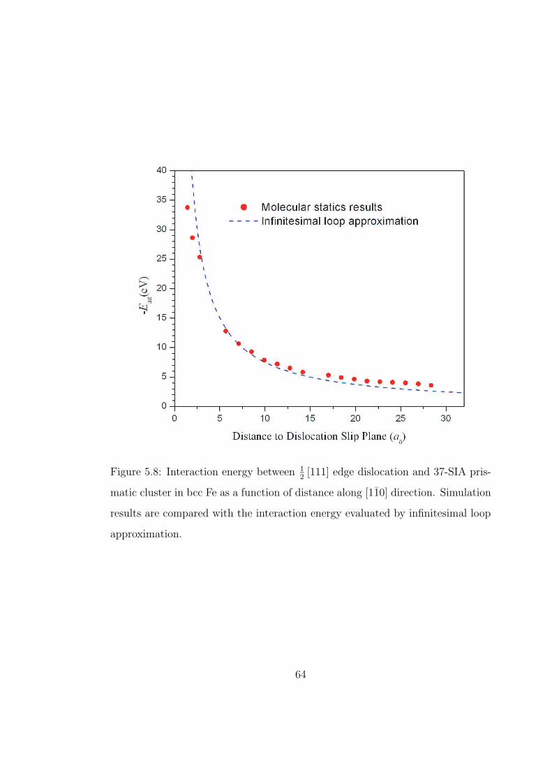
Figure 5.8: Interaction energy between 12[111] edge dislocation and 37-SIA pris-
matic cluster in bcc Fe as a function of distance along [110] direction. Simulation
results are compared with the interaction energy evaluated by infinitesimal loop
approximation.
64
Nasr Ghoniem
Pencil
Nasr Ghoniem
Pencil
Nasr Ghoniem
Pencil
Nasr Ghoniem
Pencil
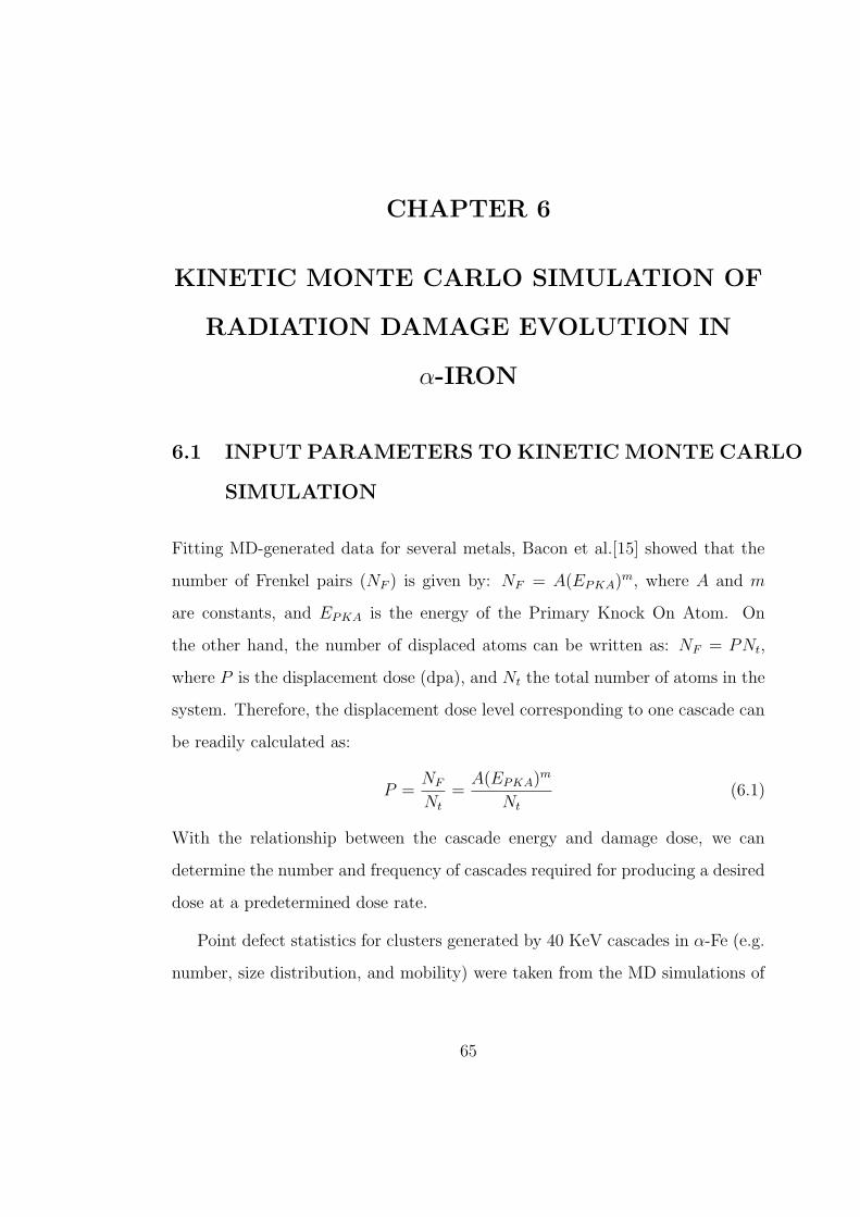
CHAPTER 6
KINETIC MONTE CARLO SIMULATION OF
RADIATION DAMAGE EVOLUTION IN
α-IRON
6.1 INPUT PARAMETERS TO KINETIC MONTE CARLO
SIMULATION
Fitting MD-generated data for several metals, Bacon et al.[15] showed that the
number of Frenkel pairs (NF ) is given by: NF = A(EPKA)m, where A and m
are constants, and EPKA is the energy of the Primary Knock On Atom. On
the other hand, the number of displaced atoms can be written as: NF = PNt,
where P is the displacement dose (dpa), and Nt the total number of atoms in the
system. Therefore, the displacement dose level corresponding to one cascade can
be readily calculated as:
P =NF
Nt
=A(EPKA)m
Nt
(6.1)
With the relationship between the cascade energy and damage dose, we can
determine the number and frequency of cascades required for producing a desired
dose at a predetermined dose rate.
Point defect statistics for clusters generated by 40 KeV cascades in α-Fe (e.g.
number, size distribution, and mobility) were taken from the MD simulations of
65
Nasr Ghoniem
Pencil
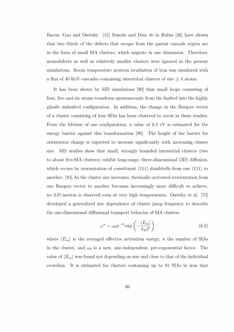
Bacon, Gao and Osetsky. [15] Soneda and Diaz de la Rubia [26] have shown
that two thirds of the defects that escape from the parent cascade region are
in the form of small SIA clusters, which migrate in one dimension. Therefore,
monodefects as well as relatively smaller clusters were ignored in the present
simulations. Room temperature neutron irradiation of iron was simulated with
a flux of 40 KeV cascades containing interstitial clusters of size ≥ 4 atoms.
It has been shown by MD simulations [90] that small loops consisting of
four, five and six atoms transform spontaneously from the faulted into the highly
glissile unfaulted configuration. In addition, the change in the Burgers vector
of a cluster consisting of four SIAs has been observed to occur in these studies.
From the lifetime of one configuration, a value of 0.4 eV is estimated for the
energy barrier against this transformation [90]. The height of the barrier for
orientation change is expected to increase significantly with increasing cluster
size. MD studies show that small, strongly bounded interstitial clusters (two
to about five-SIA clusters) exhibit long-range, three-dimensional (3D) diffusion,
which occurs by reorientation of constituent 〈111〉 dumbbells from one 〈111〉 to
another. [84] As the cluster size increases, thermally-activated reorientation from
one Burgers vector to another becomes increasingly more difficult to achieve,
no 3-D motion is observed even at very high temperatures. Osetsky et al. [73]
developed a generalized size dependence of cluster jump frequency to describe
the one-dimensional diffusional transport behavior of SIA clusters
ωn = ω0n−S exp
(
−〈Em〉kBT
)
(6.2)
where 〈Em〉 is the averaged effective activation energy, n the number of SIAs
in the cluster, and ω0 is a new, size-independent, pre-exponential factor. The
value of 〈Em〉 was found not depending on size and close to that of the individual
crowdion. It is estimated for clusters containing up to 91 SIAs in iron that
66
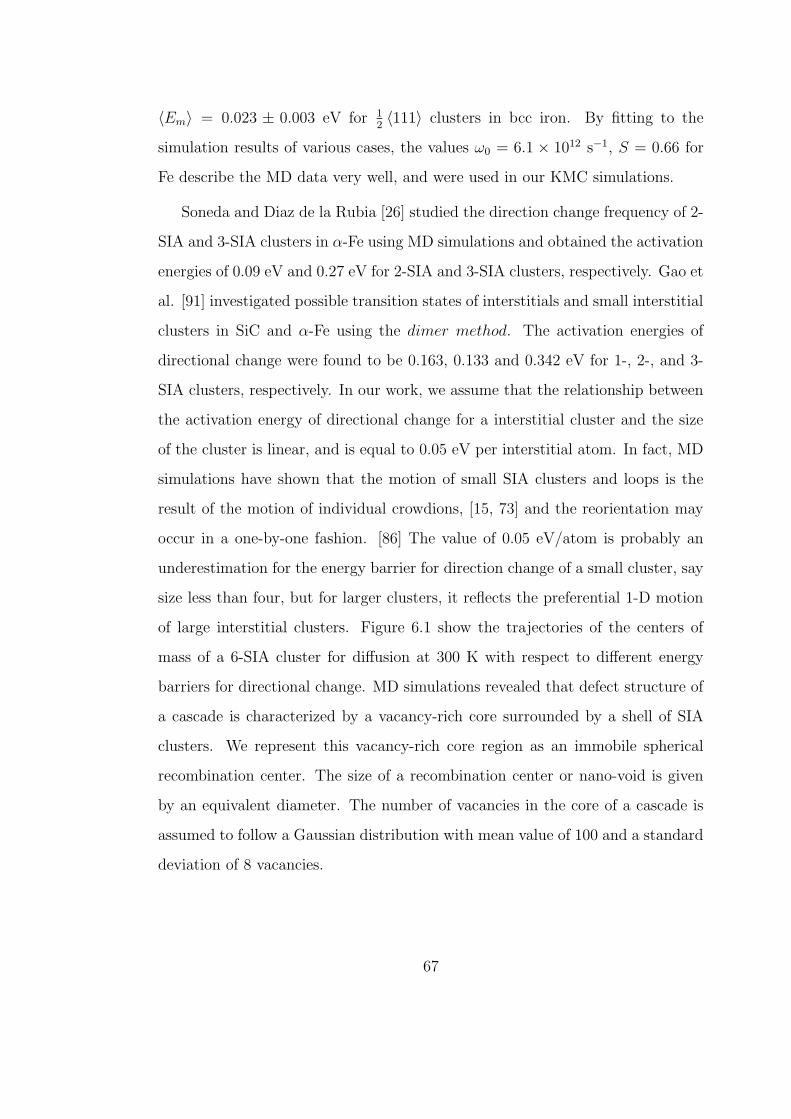
〈Em〉 = 0.023 ± 0.003 eV for 12〈111〉 clusters in bcc iron. By fitting to the
simulation results of various cases, the values ω0 = 6.1 × 10¹² s−1, S = 0.66 for
Fe describe the MD data very well, and were used in our KMC simulations.
Soneda and Diaz de la Rubia [26] studied the direction change frequency of 2-
SIA and 3-SIA clusters in α-Fe using MD simulations and obtained the activation
energies of 0.09 eV and 0.27 eV for 2-SIA and 3-SIA clusters, respectively. Gao et
al. [91] investigated possible transition states of interstitials and small interstitial
clusters in SiC and α-Fe using the dimer method. The activation energies of
directional change were found to be 0.163, 0.133 and 0.342 eV for 1-, 2-, and 3-
SIA clusters, respectively. In our work, we assume that the relationship between
the activation energy of directional change for a interstitial cluster and the size
of the cluster is linear, and is equal to 0.05 eV per interstitial atom. In fact, MD
simulations have shown that the motion of small SIA clusters and loops is the
result of the motion of individual crowdions, [15, 73] and the reorientation may
occur in a one-by-one fashion. [86] The value of 0.05 eV/atom is probably an
underestimation for the energy barrier for direction change of a small cluster, say
size less than four, but for larger clusters, it reflects the preferential 1-D motion
of large interstitial clusters. Figure 6.1 show the trajectories of the centers of
mass of a 6-SIA cluster for diffusion at 300 K with respect to different energy
barriers for directional change. MD simulations revealed that defect structure of
a cascade is characterized by a vacancy-rich core surrounded by a shell of SIA
clusters. We represent this vacancy-rich core region as an immobile spherical
recombination center. The size of a recombination center or nano-void is given
by an equivalent diameter. The number of vacancies in the core of a cascade is
assumed to follow a Gaussian distribution with mean value of 100 and a standard
deviation of 8 vacancies.
67
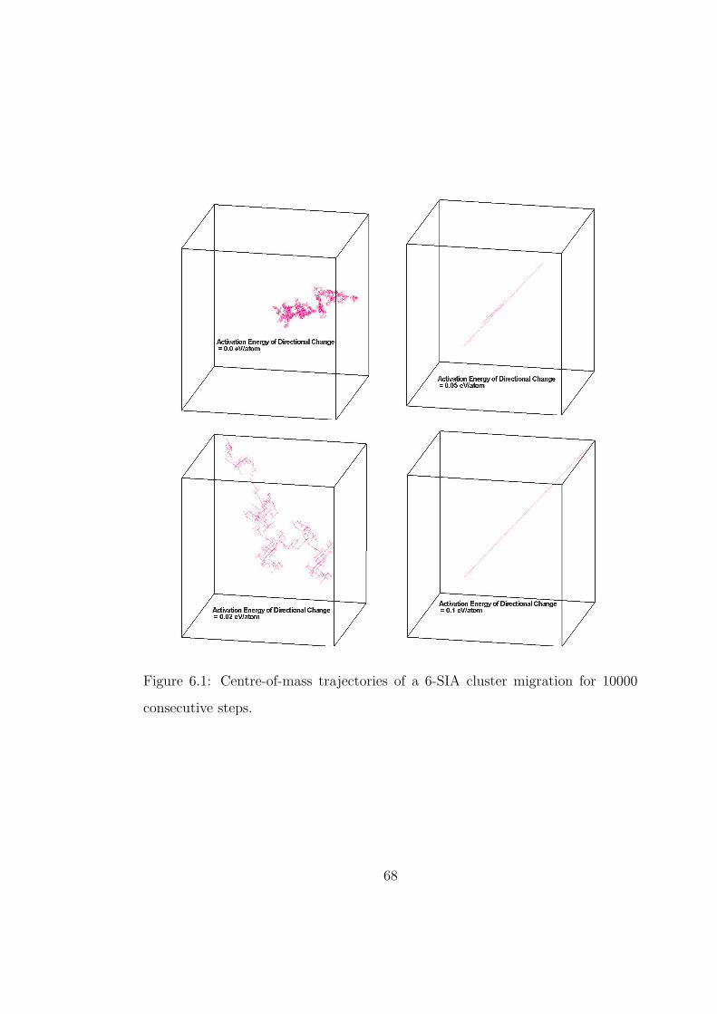
Figure 6.1: Centre-of-mass trajectories of a 6-SIA cluster migration for 10000
consecutive steps.
68
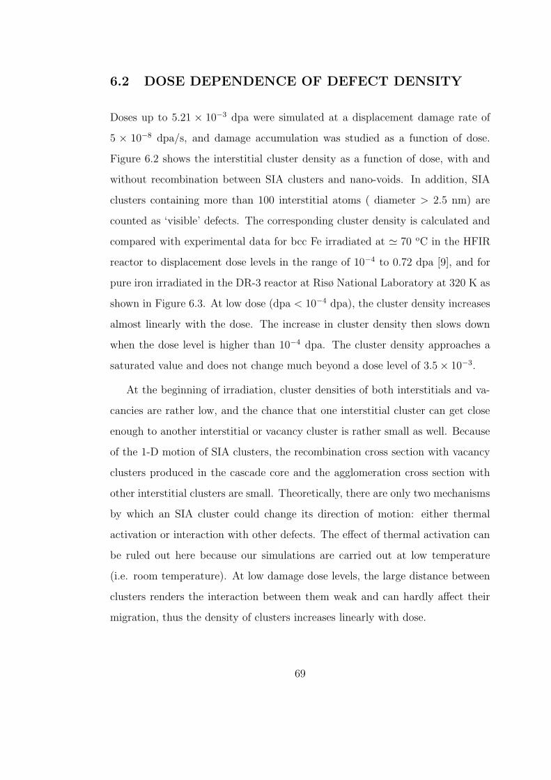
6.2 DOSE DEPENDENCE OF DEFECT DENSITY
Doses up to 5.21 × 10⁻³ dpa were simulated at a displacement damage rate of
5 × 10⁻⁸ dpa/s, and damage accumulation was studied as a function of dose.
Figure 6.2 shows the interstitial cluster density as a function of dose, with and
without recombination between SIA clusters and nano-voids. In addition, SIA
clusters containing more than 100 interstitial atoms ( diameter > 2.5 nm) are
counted as ‘visible’ defects. The corresponding cluster density is calculated and
compared with experimental data for bcc Fe irradiated at ' 70 oC in the HFIR
reactor to displacement dose levels in the range of 10−4 to 0.72 dpa [9], and for
pure iron irradiated in the DR-3 reactor at Risø National Laboratory at 320 K as
shown in Figure 6.3. At low dose (dpa < 10−4 dpa), the cluster density increases
almost linearly with the dose. The increase in cluster density then slows down
when the dose level is higher than 10−4 dpa. The cluster density approaches a
saturated value and does not change much beyond a dose level of 3.5 × 10⁻³.
At the beginning of irradiation, cluster densities of both interstitials and va-
cancies are rather low, and the chance that one interstitial cluster can get close
enough to another interstitial or vacancy cluster is rather small as well. Because
of the 1-D motion of SIA clusters, the recombination cross section with vacancy
clusters produced in the cascade core and the agglomeration cross section with
other interstitial clusters are small. Theoretically, there are only two mechanisms
by which an SIA cluster could change its direction of motion: either thermal
activation or interaction with other defects. The effect of thermal activation can
be ruled out here because our simulations are carried out at low temperature
(i.e. room temperature). At low damage dose levels, the large distance between
clusters renders the interaction between them weak and can hardly affect their
migration, thus the density of clusters increases linearly with dose.
69
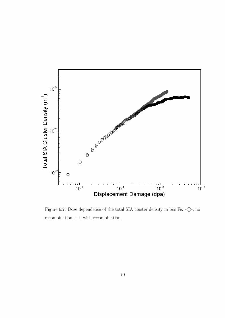
Figure 6.2: Dose dependence of the total SIA cluster density in bcc Fe: -©-, no
recombination; -- with recombination.
70
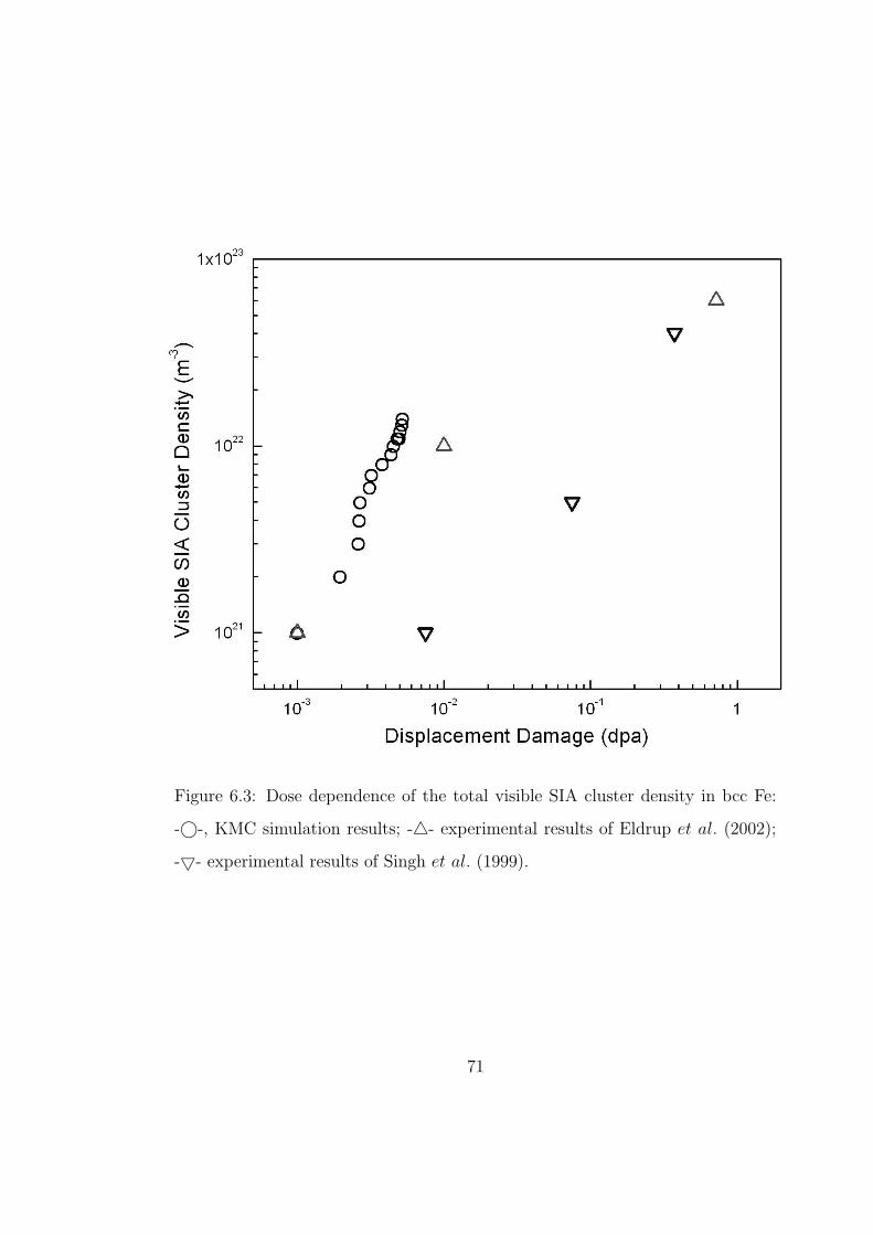
Figure 6.3: Dose dependence of the total visible SIA cluster density in bcc Fe:
-©-, KMC simulation results; -4- experimental results of Eldrup et al. (2002);
-5- experimental results of Singh et al. (1999).
71
When the damage builds up to an appreciable level, on the order of 10−4 dpa,
the simulation box becomes crowded with defects. The probability of mutual in-
teraction between clusters becomes appreciable, leading to more pronounced re-
combination and agglomeration events. Consequently, these non-linear reactions
slow down the increase in the density of SIA clusters. At higher accumulated
damage levels, on the order of 3.5 × 10⁻³ dpa in the present case, the number
of SIA clusters that recombine or coalesce reaches dynamic equilibrium with the
number of clusters produced by fresh cascades. Then, SIA cluster density in the
simulation box reaches a saturation level.
It is found that the presence of nano-voids has a significant effect on the
evolution dynamics of SIA clusters. As we can see in Figure 6.2, at a dose level
lower than 5 × 10⁻⁴ dpa, the difference between SIA cluster densities, with and
without nano-voids, is not large. However, when nano-voids are included in the
simulation, the surviving SIA cluster density deviates from the case when nano-
voids are not included. For example, the density of surviving SIA clusters is less
by a factor of 2 at 1.5 × 10⁻³ dpa, when nano-voids are included.
Although the density of SIA clusters reaches steady state after 3.5×10⁻³ dpa,
SIA cluster sizes continue to grow, and the density of visible clusters increases as
well. In order to compare the results from our simulations with experimentally
measured cluster densities, it is necessary to assume a minimum size that can be
resolved in experiments. A value between 1.5 and 2 nm in diameter is quoted
in the literature as the minimum size resolved by TEM [92]. In the present
simulations, we assume that SIA clusters containing more than 100 atoms are
visible. It is shown in Figure 6.3 that the density of visible SIA clusters obtained
in the simulations presented here is larger than the experimental measurement at
high dose levels. The high mobility of SIA clusters allows them to be absorbed
72
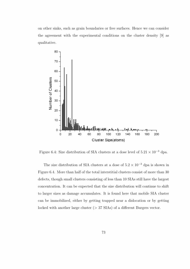
on other sinks, such as grain boundaries or free surfaces. Hence we can consider
the agreement with the experimental conditions on the cluster density [9] as
qualitative.
Figure 6.4: Size distribution of SIA clusters at a dose level of 5.21 × 10⁻³ dpa.
The size distribution of SIA clusters at a dose of 5.2 × 10⁻³ dpa is shown in
Figure 6.4. More than half of the total interstitial clusters consist of more than 30
defects, though small clusters consisting of less than 10 SIAs still have the largest
concentration. It can be expected that the size distribution will continue to shift
to larger sizes as damage accumulates. It is found here that mobile SIA cluster
can be immobilized, either by getting trapped near a dislocation or by getting
locked with another large cluster (> 37 SIAs) of a different Burgers vector.
73
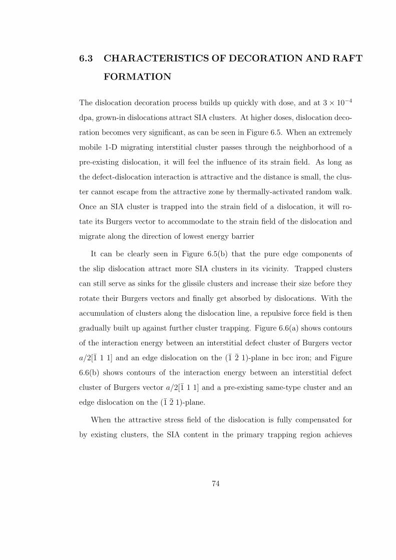
6.3 CHARACTERISTICS OF DECORATION AND RAFT
FORMATION
The dislocation decoration process builds up quickly with dose, and at 3 × 10⁻⁴
dpa, grown-in dislocations attract SIA clusters. At higher doses, dislocation deco-
ration becomes very significant, as can be seen in Figure 6.5. When an extremely
mobile 1-D migrating interstitial cluster passes through the neighborhood of a
pre-existing dislocation, it will feel the influence of its strain field. As long as
the defect-dislocation interaction is attractive and the distance is small, the clus-
ter cannot escape from the attractive zone by thermally-activated random walk.
Once an SIA cluster is trapped into the strain field of a dislocation, it will ro-
tate its Burgers vector to accommodate to the strain field of the dislocation and
migrate along the direction of lowest energy barrier
It can be clearly seen in Figure 6.5(b) that the pure edge components of
the slip dislocation attract more SIA clusters in its vicinity. Trapped clusters
can still serve as sinks for the glissile clusters and increase their size before they
rotate their Burgers vectors and finally get absorbed by dislocations. With the
accumulation of clusters along the dislocation line, a repulsive force field is then
gradually built up against further cluster trapping. Figure 6.6(a) shows contours
of the interaction energy between an interstitial defect cluster of Burgers vector
a/2[1 1 1] and an edge dislocation on the (1 2 1)-plane in bcc iron; and Figure
6.6(b) shows contours of the interaction energy between an interstitial defect
cluster of Burgers vector a/2[1 1 1] and a pre-existing same-type cluster and an
edge dislocation on the (1 2 1)-plane.
When the attractive stress field of the dislocation is fully compensated for
by existing clusters, the SIA content in the primary trapping region achieves
74
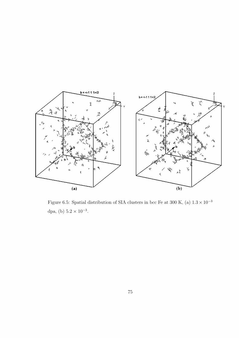
Figure 6.5: Spatial distribution of SIA clusters in bcc Fe at 300 K, (a) 1.3× 10⁻³
dpa, (b) 5.2 × 10⁻³.
75
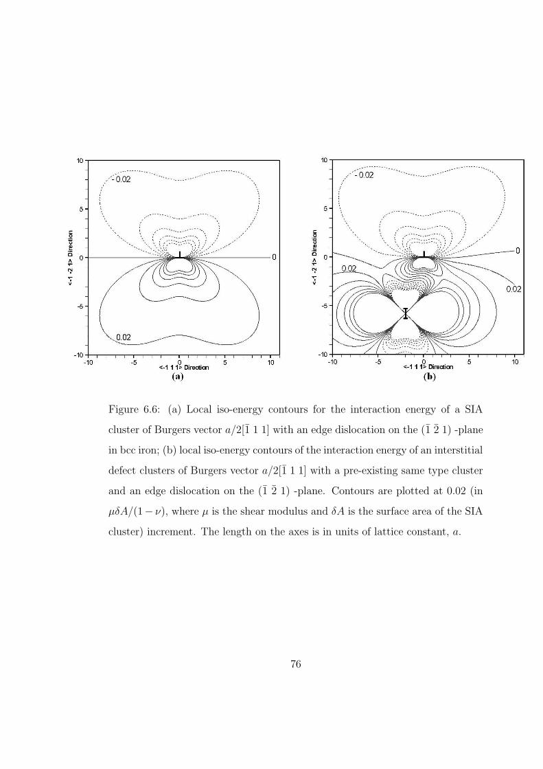
Figure 6.6: (a) Local iso-energy contours for the interaction energy of a SIA
cluster of Burgers vector a/2[1 1 1] with an edge dislocation on the (1 2 1) -plane
in bcc iron; (b) local iso-energy contours of the interaction energy of an interstitial
defect clusters of Burgers vector a/2[1 1 1] with a pre-existing same type cluster
and an edge dislocation on the (1 2 1) -plane. Contours are plotted at 0.02 (in
µδA/(1− ν), where µ is the shear modulus and δA is the surface area of the SIA
cluster) increment. The length on the axes is in units of lattice constant, a.
76
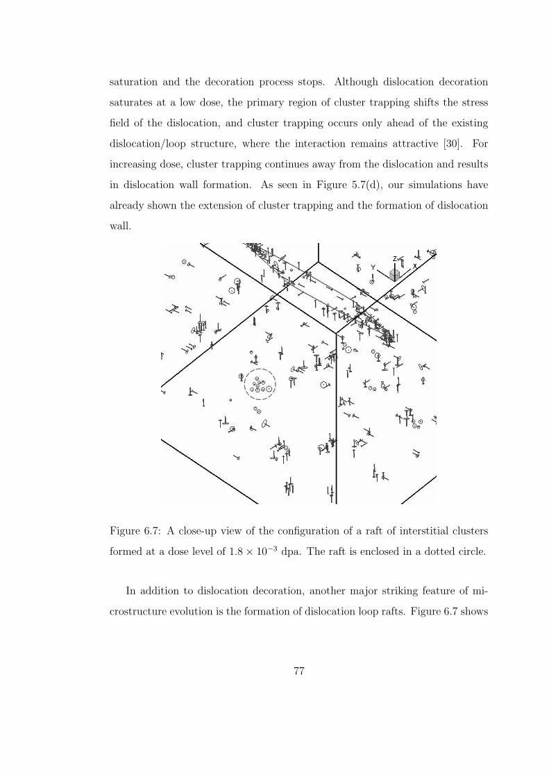
saturation and the decoration process stops. Although dislocation decoration
saturates at a low dose, the primary region of cluster trapping shifts the stress
field of the dislocation, and cluster trapping occurs only ahead of the existing
dislocation/loop structure, where the interaction remains attractive [30]. For
increasing dose, cluster trapping continues away from the dislocation and results
in dislocation wall formation. As seen in Figure 5.7(d), our simulations have
already shown the extension of cluster trapping and the formation of dislocation
wall.
Figure 6.7: A close-up view of the configuration of a raft of interstitial clusters
formed at a dose level of 1.8 × 10⁻³ dpa. The raft is enclosed in a dotted circle.
In addition to dislocation decoration, another major striking feature of mi-
crostructure evolution is the formation of dislocation loop rafts. Figure 6.7 shows
77
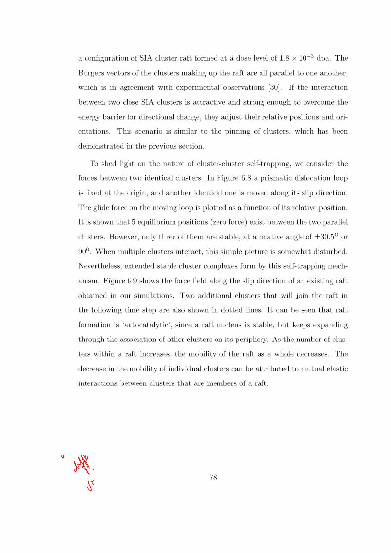
a configuration of SIA cluster raft formed at a dose level of 1.8 × 10⁻³ dpa. The
Burgers vectors of the clusters making up the raft are all parallel to one another,
which is in agreement with experimental observations [30]. If the interaction
between two close SIA clusters is attractive and strong enough to overcome the
energy barrier for directional change, they adjust their relative positions and ori-
entations. This scenario is similar to the pinning of clusters, which has been
demonstrated in the previous section.
To shed light on the nature of cluster-cluster self-trapping, we consider the
forces between two identical clusters. In Figure 6.8 a prismatic dislocation loop
is fixed at the origin, and another identical one is moved along its slip direction.
The glide force on the moving loop is plotted as a function of its relative position.
It is shown that 5 equilibrium positions (zero force) exist between the two parallel
clusters. However, only three of them are stable, at a relative angle of ±30.5o or
90o. When multiple clusters interact, this simple picture is somewhat disturbed.
Nevertheless, extended stable cluster complexes form by this self-trapping mech-
anism. Figure 6.9 shows the force field along the slip direction of an existing raft
obtained in our simulations. Two additional clusters that will join the raft in
the following time step are also shown in dotted lines. It can be seen that raft
formation is ‘autocatalytic’, since a raft nucleus is stable, but keeps expanding
through the association of other clusters on its periphery. As the number of clus-
ters within a raft increases, the mobility of the raft as a whole decreases. The
decrease in the mobility of individual clusters can be attributed to mutual elastic
interactions between clusters that are members of a raft.
78
Nasr Ghoniem
Pencil
Nasr Ghoniem
Pencil
Nasr Ghoniem
Pencil
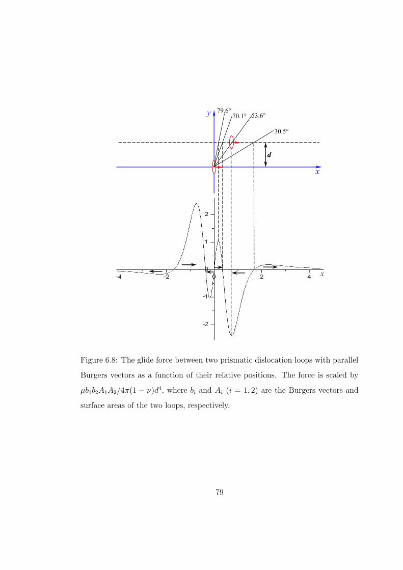
79.6° 53.6°
30.5°
70.1°
x
y
d
Figure 6.8: The glide force between two prismatic dislocation loops with parallel
Burgers vectors as a function of their relative positions. The force is scaled by
µb1b2A1A2/4π(1 − ν)d4, where bi and Ai (i = 1, 2) are the Burgers vectors and
surface areas of the two loops, respectively.
79
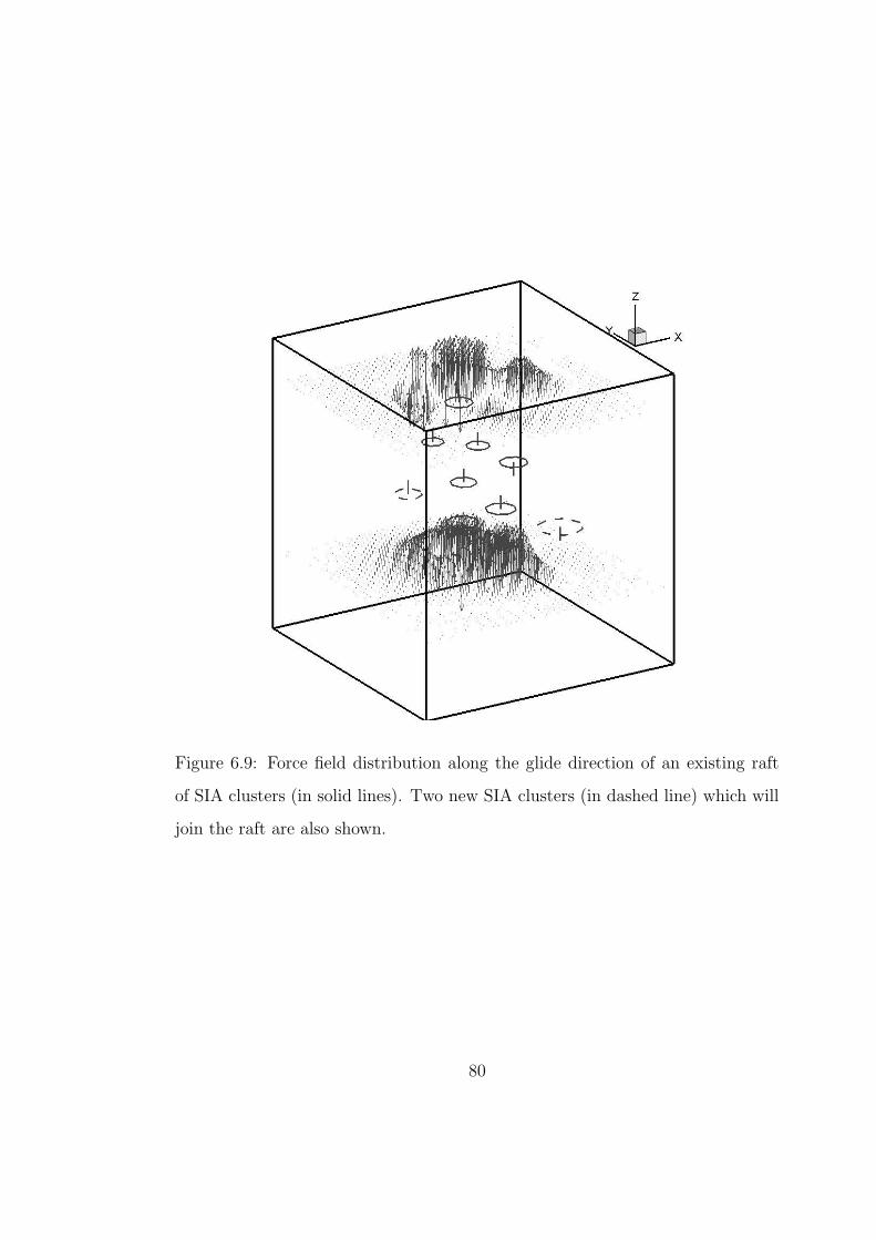
Figure 6.9: Force field distribution along the glide direction of an existing raft
of SIA clusters (in solid lines). Two new SIA clusters (in dashed line) which will
join the raft are also shown.
80
6.4 GENERAL CONDITIONS FOR DECORATION AND
RAFT FORMATION
Trinkaus et al. [30] have shown that a grown-in dislocation would have a large
drainage area for accumulating one-dimensionally migrating glissile loops in its
neighborhood. Our simulations also demonstrate that even at a fairly low dose
of 1.3×10⁻³ dpa, clear dislocation decoration is observed. The energy barrier for
directional change is a critical parameter in controlling when, how and to what
extent dislocation decoration and raft formation occur. The maximum range for
the elastic interaction that is strong enough to overcome the barrier and thereby
leads to a Burgers vector change is strongly dependent on this parameter. In
other words, the interaction between defects and the microstructure contributes
to dislocation decoration and the formation of rafts in terms of changing the dif-
fusivity and the characteristics of mixed 1D/3D migration. Brimhall and Mastel
[27] proposed that loops move through the lattice by a combination of prismatic
glide and self-climb to form rafts. Our present simulations, however, suggest that
raft formation could be achieved just by prismatic glide and rotation of glissile
SIA clusters. A necessary condition for pronounced formation of rafts is that the
group of clusters within a raft is large enough to trap a single glissile cluster in
the strain field formed by the group and prevent it from further Burgers vec-
tor rotation. Our simulations indicate that small rafts containing two or three
clusters are still mobile; more specifically, these small patches still perform 1-D
migration, although at reduced mobility. With the size of a patch increasing,
the overall mobility decreases, and a raft consisting of more than five clusters is
literally immobile. Due to thermal activation or interaction with other defects,
a SIA cluster trapped in the outer region of a raft may break away and detrap
from the raft.
81
CHAPTER 7
EFFECTS OF NEUTRON IRRADIATION ON
DYNAMIC PROPERTIES OF EDGE
DISLOCATIONS
7.1 INTRODUCTION
Plastic deformation in crystalline metals is known as a collective consequence
of the motion of large number of dislocations. An enormous amount of inves-
tigations concerned with dislocation mechanics have been performed from both
atomistic and continuum perspectives. However, modeling the behavior of large
numbers of dislocations is a computationally intensive task. Only relatively re-
cently have computational models of the collective behavior of discrete disloca-
tions been developed. Large-scale Dislocation dynamics (DD) simulations, in
which the individual dislocations are described as straight or curved segments of
line defects in an elastic solid, have been successfully used to study characteristic
plastic deformations such as dislocation pattern formation and work-hardening
relations in macroscopically homogeneously deformed solid [93, 94, 95].
It is well established that a large number of point defects and point defect
clusters are created in high-energy displacement cascades in metals exposed to ir-
radiation by high-energy neutrons [22, 15]. Atomistic simulations have shown that
small SIA clusters can form perfect loops and perform fast thermally-activated
82
Nasr Ghoniem
Pencil
Nasr Ghoniem
Pencil
Nasr Ghoniem
Pencil
one-dimensional motion in a variety of bcc, fcc and hcp metals [96, 84, 97]. The
motion and interaction of SIA clusters can lead to formation of rafts of small
dislocation loops and decoration of dislocation by loops [30, 98]. Analytical cal-
culations as well as KMC simulations have supported this conclusion. Based
on experimentally observed microstructure, the analytical CISH model [30, 12]
provides a rational explanation for the observed phenomena in post-irradiation
deformation experiments, namely, irradiation hardening and the occurrence of
yield drop. However, the materials tested in the post-irradiated state respond
to conditions that are fundamentally different from those that are likely to be
experienced by the materials subjected simultaneously to an flux of neutrons and
stresses in a real reactor environment. Under these conditions freshly generated
mobile dislocations are likely to interact with both glissile and sessile SIA clus-
ters, as well as vacancies produced continuously by cascades and it is therefore
relevant to investigate the influence of these interactions on dislocation motion.
In fact, in-reactor tensile tests have been carried out recently on both pure copper
and copper alloy in a fission reactor and results on the mechanical response and
concurrent microstructure evolution are now available [99]. In addition, atomistic
simulations of both α-iron and copper are performed to investigate interactions
between a gliding edge dislocation and decoration formed by a row of SIA loops
[100]. It is shown that SIA loops lying within a few nanometers of the dislocation
slip plane can be dragged at very high speed.
Large-scale three-dimensional DD simulations have been used to investigate
the relation between the irradiation field and mechanical behavior including ir-
radiation hardening and post-yield deformation[101]. The KMC simulations de-
scribed in previous chapters can provide valuable information on the spatial and
size distribution of defect clusters produced in displacement cascades. The mi-
crostructure predicted by KMC simulation can then be used to serve as input to
83
Nasr Ghoniem
Pencil
Nasr Ghoniem
Pencil
Nasr Ghoniem
Pencil
Nasr Ghoniem
Pencil
Nasr Ghoniem
Pencil
DD simulation to investigate radiation effect on plastic deformation in a more
realistic way.
The main objective of this chapter is to study fundamental aspects of dynam-
ics of dislocation interaction with radiation-induced defect clusters, specifically
with both glissile and sessile SIA clusters in dislocation decorations, as well as
distributed nano-voids that resemble vacancy-rich cascade core regions. The in-
vestigation of the behavior of single gliding dislocations under irradiation can
characterize the effects of interaction with various microstructures and provide
guidance to ongoing large-scale simulations. In Section 7.2, the method used in
the context is described, which is a modified version of the parametric disloca-
tion dynamics method developed by Ghoniem et al.[102], with considering inertial
effects (i.e. the kinetic energy of moving dislocations). To describe the drag influ-
ence of SIA clusters on a gliding dislocation for the configurations generated by
KMC simulations, a model developed by Rong et al.[103] is incorporated into the
current simulation scheme in Section 7.3. The phenomenon of radiation-induced
increase in the yield stress is then discussed from two perspectives, specifically
for glide resistance to dislocation motion due to distributed vacancy clusters in
Section 7.4.1 and the pinning effect of SIA clusters to decorated dislocations in
Section 7.4, respectively. Finally, the dislocation glide affected by interaction of
dislocations with various obstacles to their glide is investigated in Section 7.5.
7.2 PARAMETRIC DISLOCATION DYNAMICS
Dislocations are line singularities in solid materials. A new parametric method
of dislocation dynamics has recently been developed and applied to study three-
dimensional problems of deformation in material deformation[77, 102, 104, 95].
The basic idea of parametric dislocation dynamics method is to represent dislo-
84
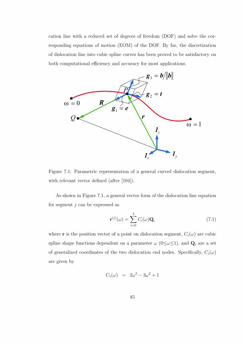
cation line with a reduced set of degrees of freedom (DOF) and solve the cor-
responding equations of motion (EOM) of the DOF. By far, the discretization
of dislocation line into cubic spline curves has been proved to be satisfactory on
both computational efficiency and accuracy for most applications.
Figure 7.1: Parametric representation of a general curved dislocation segment,
with relevant vector defined (after [104]).
As shown in Figure 7.1, a general vector form of the dislocation line equation
for segment j can be expressed as
r(j)(ω) =4∑
i=0
Ci(ω)Qi (7.1)
where r is the position vector of a point on dislocation segment, Ci(ω) are cubic
spline shape functions dependent on a parameter ω (0≤ω≤1), and Qi are a set
of generalized coordinates of the two dislocation end nodes. Specifically, Ci(ω)
are given by
C1(ω) = 2ω3 − 3ω2 + 1
85
C2(ω) = −2ω3 + 3ω2
C3(ω) = ω3 − 2ω2 + ω
C4(ω) = ω3 − ω2 (7.2)
and Qi are:
Q1 = P(j)(0), Q2 = P(j)(1),
Q3 = T(j)(0), Q4 = T(j)(1) (7.3)
where P(j)(i) and T(j)(i) (i = 1, 2) are the position and tangent vectors of the
beginning and ending node of segment j, respectively.
7.2.1 THE EQUATION OF MOTION
Under most dynamic conditions, dislocations move so slowly that the dynamic
stresses and displacements are approximated quite accurately by the static so-
lutions. Therefore, in existing DD methodology the dynamic term has been
ignored for the sake of computational simplicity. However, dynamic effects are
thought to be important in some specific scenarios, for example, in the study
of dislocations being suddenly released from cluster atmospheres under high ap-
plied stresses. Here, by reinstating the kinetic energy which was ignored in the
derivation based on thermodynamics by Ghoniem et al.[102], we present a mod-
ified variational form for the equations of motion (EOM) for dislocation loops.
Following Ghoniem et al.[102], consider a body in thermodynamic equilibrium, of
volume Ω, and its boundary S, containing a dislocation loop in an initial position
(1), as shown in Figure 7.2. By the prescribed external mechanical forces, as well
as thermodynamic internal forces, the dislocation loop will experience transition
from the initial state to a new on designated as (2). According to the first law
of thermodynamics, the following condition of energy conservation must be met
86
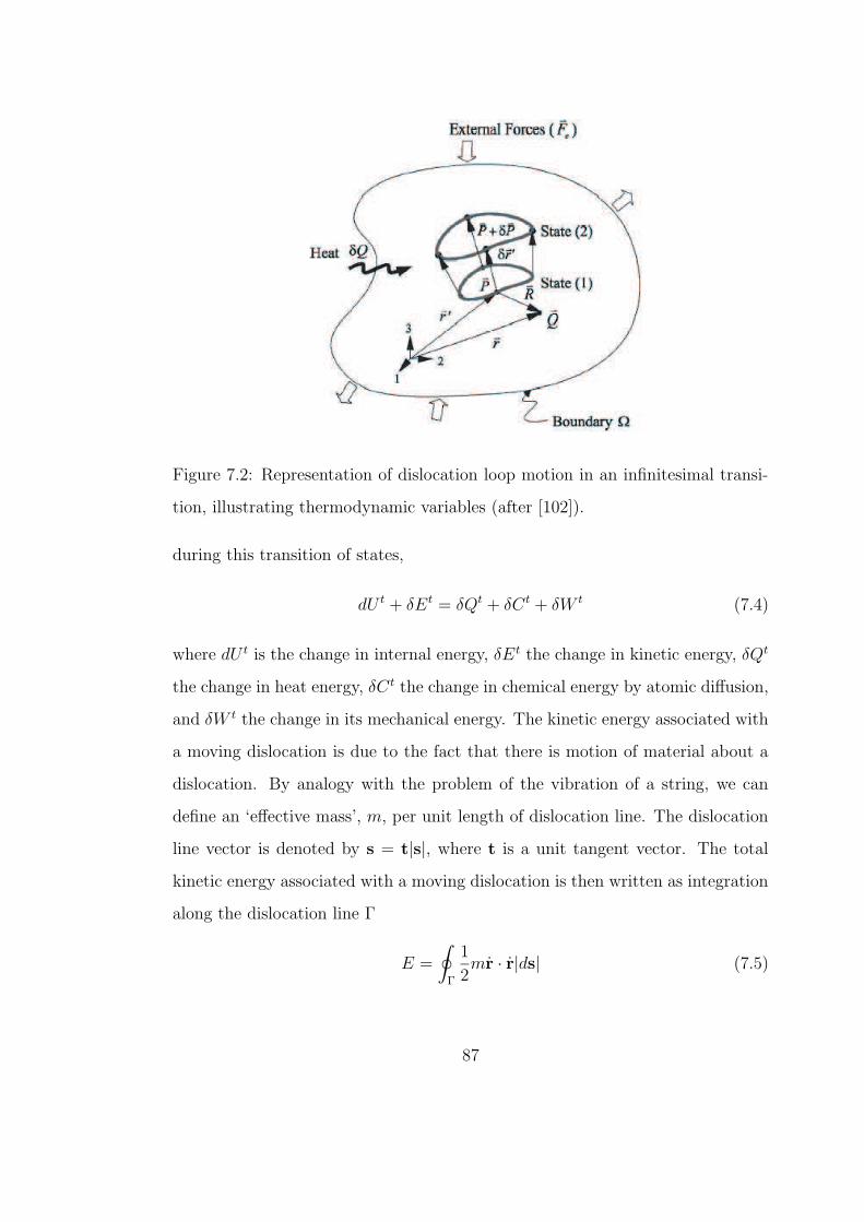
Figure 7.2: Representation of dislocation loop motion in an infinitesimal transi-
tion, illustrating thermodynamic variables (after [102]).
during this transition of states,
dU t + δEt = δQt + δCt + δW t (7.4)
where dU t is the change in internal energy, δEt the change in kinetic energy, δQt
the change in heat energy, δC t the change in chemical energy by atomic diffusion,
and δW t the change in its mechanical energy. The kinetic energy associated with
a moving dislocation is due to the fact that there is motion of material about a
dislocation. By analogy with the problem of the vibration of a string, we can
define an ‘effective mass’, m, per unit length of dislocation line. The dislocation
line vector is denoted by s = t|s|, where t is a unit tangent vector. The total
kinetic energy associated with a moving dislocation is then written as integration
along the dislocation line Γ
E =
∮
Γ
1
2mr · r|ds| (7.5)
87
Nasr Ghoniem
Pencil
Nasr Ghoniem
Pencil
where r is the displacement vector of core atoms of the dislocation loop.
Consider an infinitesimal variation in the position of a dislocation loop in a
time interval δt. During loop motion from state (1) to state (2) in Figure 7.2,
the variation in kinetic energy over this period of time can be shown as
δEt =d
dt
[∮
Γ
1
2mr·r|ds|
]
δt
=
∮
Γ
mr·rδt|ds|
=
∮
Γ
mr·δr|ds|
The variation in kinetic energy during time interval δt reads
δEt =
∮
Γ
mr·δr|ds|dt (7.6)
Following the treatments in Ref. [102] with including the kinetic energy term, it
can be shown that during the transition the total Gibbs energy change over δt,
δGt, is given by
δGt = −∮
Γ
(f t − mr
)· δr|ds| ≤ 0 (7.7)
where f t = fs + fO + fPK is the total force. Here the following generalized thermo-
dynamic forces is defined similar to Ghoniem et al.[102]: fPK ≡ the Peach-Koehler
force per unit length, fS ≡ the self-force per unit length, and fO ≡ the totial os-
motic force[105] for point defect γ per unit length, where γ = (−1) for vacancies
and (+1) for interstitials.
In compact tensor form, Equation 7.8 can be written as
δGt = −∮
Γ
(f t
k − mrk
)δrk|ds| ≤ 0 (7.8)
On the other hand, we can denote Bαk as a diagonal resistivity (inverse mo-
bility) matrix with respect to the drift velocity V, and follow the same procedure
88
by Ghoniem et al.[102] to obtain the following equivalent form of Gibbs energy
variation:
δGt = −∮
Γ
BαkVαδrk|ds|dt ≤ 0 (7.9)
The resistivity matrix can have three independent components (two for glide
and one for climb), depending on the crystal structure and temperature. It is
expressed as
Bαk =
B1 0 0
0 B2 0
0 0 B3
(7.10)
Combining Equation 7.8 with Equation 7.9, we have
∮
Γ
(f t
k − mrk − BαkVα
)δrk|ds|dt ≤ 0 (7.11)
The magnitude of the virtual displacement δdk and the the time interval [t1, t2]
are not specified, and hence ban be arbitrary. This implies that Equation 7.11
represents force balance on every atom of the dislocation core, where the acting
force component f tk is balanced by the combination of viscous dissipation in the
crystal via the term BαkVα and inertial force mrk. However, it is the integral EOM
that has more sense in practical applications from the perspective of reducing the
independent DOF that describe loop motion.
Now we can take the general procedure of PDD method, and divide the dis-
location loop into Ns curved segments. The line integral in Equation 7.11 can be
written as a sum over each parametric segment j, i.e.,
Ns∑
j=1
∫
j
δri
(f t
i − mri − BikVk
)|ds| = 0 (7.12)
In each segment j, we can choose a set of generalized coordinates qm at the two
89
Nasr Ghoniem
Pencil
ends, thus allowing parametrization of the form:
ri(ω) =
NDF∑
i=0
Cim(ω)qm (7.13)
where Cim(ω) are shape functions, dependent on the parameter ω (0 ≤ ω ≤ 1),
and NDF is the number of total generalized coordinates at two ends of the loop
segment. The arc length differential for segment j is given by
|ds| = (rl,url,u) 12
dω =
(NDF∑
p,s=1
qpClp,ωCls,ωqs
) 12
dω (7.14)
Substituting all these to the integral form of the governing EOM 7.12, we obtain:
Ns∑
j=1
∫ 1
0
NDF∑
m=1
δqmCim(ω)
[
f ti − Bik
NDF∑
n=1
Cknqn,t − m
NDF∑
j=1
Cijqj,tt
]
×(
NDF∑
p,s=1
qpClp,ωCls,ωqs
) 12
dω = 0. (7.15)
Let,
fm =
∫ 1
0
f ti Cim(ω)
(NDF∑
p,s=1
qpClp,ωCls,ωqs
) 12
dω, (7.16)
γmn =
∫ 1
0
Cim(ω)BikCkn(ω)
(NDF∑
p,s=1
qpClp,ωCls,ωqs
) 12
dω, (7.17)
and
ηmn =
∫ 1
0
Cim(ω)mCin(ω)
(NDF∑
p,s=1
qpClp,ωCls,ωqs
) 12
dω. (7.18)
For the entire dislocation loop, we map all local DOFs q(j)i of each segment j
onto a set of global coordinates, shuch that the global coordinates are equal to
the local coordinates at each beginning node of the segment:
q(1)1 , q
(1)2 , q
(1)3 , . . . , q
(2)1 , q
(2)2 , q
(2)3 , . . .
= Q1, Q2, Q3, . . . , QNtotT (7.19)
90
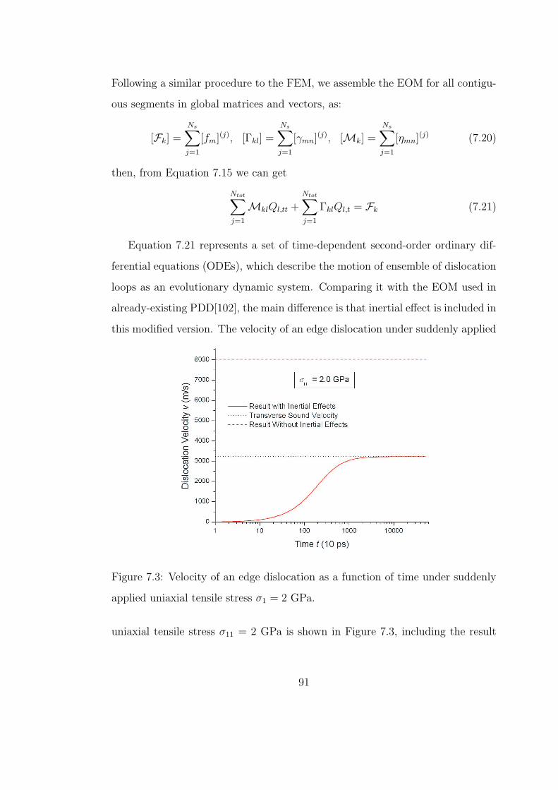
Following a similar procedure to the FEM, we assemble the EOM for all contigu-
ous segments in global matrices and vectors, as:
[Fk] =Ns∑
j=1
[fm](j), [Γkl] =Ns∑
j=1
[γmn](j), [Mk] =Ns∑
j=1
[ηmn](j) (7.20)
then, from Equation 7.15 we can get
Ntot∑
j=1
MklQl,tt +Ntot∑
j=1
ΓklQl,t = Fk (7.21)
Equation 7.21 represents a set of time-dependent second-order ordinary dif-
ferential equations (ODEs), which describe the motion of ensemble of dislocation
loops as an evolutionary dynamic system. Comparing it with the EOM used in
already-existing PDD[102], the main difference is that inertial effect is included in
this modified version. The velocity of an edge dislocation under suddenly applied
Figure 7.3: Velocity of an edge dislocation as a function of time under suddenly
applied uniaxial tensile stress σ1 = 2 GPa.
uniaxial tensile stress σ11 = 2 GPa is shown in Figure 7.3, including the result
91
Nasr Ghoniem
Pencil
Nasr Ghoniem
Pencil
with considering inertial effect as well as that without. The current EOM enables
the dislocation velocity to increase gradually from zero to a saturate value, and
the transverse sound velocity is the upper limit; while by the old EOM[102] the
velocity can abruptly jump to an unrealistic high value of more than 8000 m/s
without experiencing a course of increasing.
Observing the EOM 7.21, it can be seen that there are two material properties
that control the motion of dislocation: one is the mass matrix [Mkl] of a dislo-
cation in connection with the kinetic energy it carries while moving at constant
velocity; and the other is the resistivity matrix [Γkl] in connection with the dis-
sipation of energy while a dislocation moves at its steady-state velocity under an
essentially constant driving forces. A dynamic interaction between mass forces
and resistant forces comes into play when the driving forces varies abruptly: for
example, when the applied stress is suddenly dropped, or when the dislocation is
suddenly exposed to an increased or decreased glide resistance by, say, running
into an isolated barrier or being released from a pinning position. In principle,
the kinetic energy must then be dissipated before the dislocation comes to rest.
Under certain circumstances, inertial effects may assistant a dislocation to over-
come an obstacle: when the mass is large, the resistance is small, and the change
in net driving force is rapid.
Such inertial effects have, in the existing DD studies, been largely neglected:
dislocation have been considered to be overdamped [106], i.e. moving at their
resistivity-limited velocity, at all times. However, dislocation elements in real
materials experience rapidly changing driving forces, especially when interacting
with various obstacles, and the possibility of inertial effects must be taken into
account.
92
Nasr Ghoniem
Pencil
Nasr Ghoniem
Pencil
Nasr Ghoniem
Pencil
7.2.2 THE MASS OF DISLOCATIONS
We have already defined m as the effective mass per unit length of the dislocation
in Section 7.2.1. By analogy with the formula for kinetic energy in mechanics, we
can calculate the value of m in terms of the kinetic energy of a straight dislocation
segment moving at uniform velocity. For a screw dislocation, it has been shown
that the sum of the kinetic energy Ek and the potential energy Ee of a unit length
of dislocation moving at a constant velocity v is given by[107, 108]
E = Ek + Ee = Es/(1 − v2/C2t )
12 (7.22)
where Es is the self-energy per unit length of screw dislocation at rest, and Ct is
the transverse sound velocity and its value is obtained from Ct ≡√
µρ
in terms
of the shear modulus µ and the mass density of the materials ρ. The theory of
dislocation motion in isotropic media at uniform velocity concludes that dislo-
cation motion is quite analogous to the motion of particles in special relativity
theory[108]. The energy of the dislocation becomes infinite as the velocity of
transverse sound waves is approached. This sound speed, therefore, sets an up-
per limit for the speed of an ordinary dislocation.
At velocities small compared to the velocity of sound, i.e. v/Ct 1, Equation
7.22 is expanded as
E = Es
(
1 +1
2
v2
C2t
+ · · ·)
≈ Es +1
2Es
v2
C2t
(7.23)
It indicates that at low velocities the elastic energy of a screw dislocation is not
changed and the kinetic energy is given by 12Es
v2
C2t
. Since the latter term has the
same velocity dependence as the energy of a moving mass, it is natural to derive
an expression for the mass mSCREW in terms of Es and Cr at a low velocity:
mSCREW =Es
C2t
(7.24)
93
Nasr Ghoniem
Pencil
Rewriting Equation 7.24 as
Es = mSCREWC2t (7.25)
it is Einstein’s equation relating energy with rest mass, except that here Ct is
the velocity of sound instead of light. At high velocities Equation 7.22 can be
written as
E = mSCREWC2t /(1 − v2/C2
t )12 = m?
SCREWC2t (7.26)
where m?SCREW = mSCREW/(1− v2/C2
t )12 is the effective mass for a screw disloca-
tion moving at high velocities, which includes the relativistic effect of a factor of
1/(1 − v2/C2t )
12 by analogy with Einstein’s equation for a moving particle.
The energy of a moving edge dislocation cannot be described by Equation
7.23[108], and it is, therefore, impossible to define a rest mass of an edge dislo-
cation in terms of the self-energy of the stationary dislocation. However, it has
been shown[108] that at low velocities potential energy does not contain terms in
v2 and the kinetic energy of an edge dislocation is equal to
Ek =1
2Es(v
2/C2t )[1 + C4
t /C4λ
](7.27)
where Cλ =√
(λ + 2µ)/ρ is the longitudinal sound velocity. The effective mass
mEDGE of a slow moving edge dislocation would be
mEDGE =Es
C2t
(1 + C4
t /C4λ
)= mSCREW
(1 + C4
t /C4λ
)(7.28)
At high velocities the kinetic energy of the moving edge dislocation is[108]
Ek = Es
[
1
2(1 − v2/C2t )
32
− 7
2(1 − v2/C2t )
12
]
= Es7v2/C2
t − 6
2(1 − v2/C2t )
32
(7.29)
The energy approaches infinity as (1 − v2/C2t )−
32 rather than (1 − v2/C2
t )−12 as
in the case of screw dislocations. Although the definition of the dislocation mass
94
based on the equation analogous to Einstein’s equation cannot be applied to the
case of moving edge dislocation, it is still plausible to define a dislocation mass
in terms of kinetic energy as follows due to the dominance of (1 − v2/C2t )
32 .
m?EDGE =
Es
C2t
1
(1 − v2/C2t )
32
= mSCREW1
(1 − v2/C2t )
32
(7.30)
At low velocities, the mass for screw dislocations and that for edge ones are
very similar, since the transverse speed of sound Ct is usually about half the
longitudinal speed of sound Cλ. Therefore, we can use Equation 7.24 for the
mass of both kinds of dislocations. The general dislocation is neither pure screw
nor pure edge in character but is made up of a linear combination of both. The
energy of a moving dislocation of mixed character is simply the sum of the energy
of its edge component and of its screw component, and so is its mass. We can thus
use Equation 7.24 for any dislocations moving at low velocities. At high velocities
the behavior of a dislcation of mixed type will be approximately the same as that
of a pure edge dislocation, because the energy of the edge component approaches
infinity as (1 − v2/C2t )−
32 while the screw component approaches infinity much
more slowly as (1 − v2/C2t )−
12 . By a similar argument, the mass of a dislocation
of mixed character should be approximately the same as that of a pure edge
dislocation.
In Section 7.2.1, we have Equation 7.18 as the mass matrix of a dislocation
segment, which has the same form as the so-called consistent-mass matrix used in
finite element. In practice, a special form of mass matrix called ‘lumped’ matrices
are often employed due to their general economy and because they lead to some
especially attractive time-integration schemes. The simplest way to construct
lumped-mass matrices is to assume that the element’s mass is concentrated at
nodal points, and by doing that the mass matrices obtained are diagonal ones.
In our applications, we shall employ lumped-mass matrix.
95
Nasr Ghoniem
Pencil
Nasr Ghoniem
Pencil
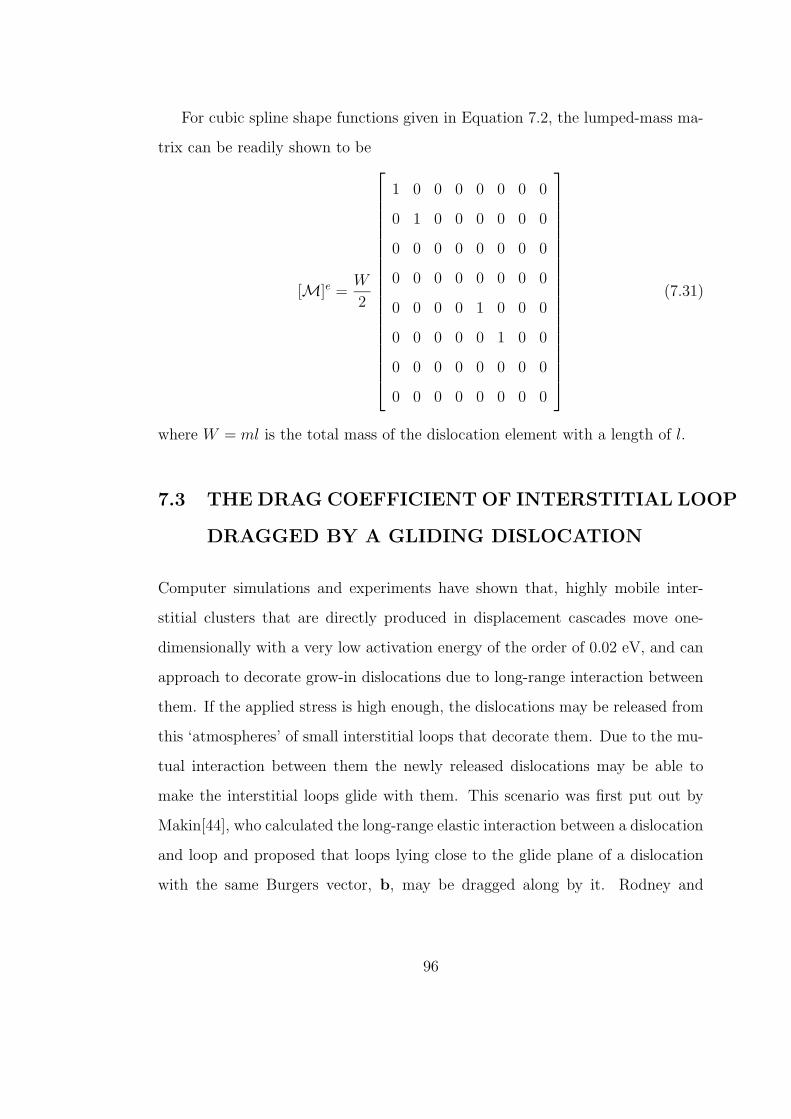
For cubic spline shape functions given in Equation 7.2, the lumped-mass ma-
trix can be readily shown to be
[M]e =W
2
1 0 0 0 0 0 0 0
0 1 0 0 0 0 0 0
0 0 0 0 0 0 0 0
0 0 0 0 0 0 0 0
0 0 0 0 1 0 0 0
0 0 0 0 0 1 0 0
0 0 0 0 0 0 0 0
0 0 0 0 0 0 0 0
(7.31)
where W = ml is the total mass of the dislocation element with a length of l.
7.3 THE DRAG COEFFICIENT OF INTERSTITIAL LOOP
DRAGGED BY A GLIDING DISLOCATION
Computer simulations and experiments have shown that, highly mobile inter-
stitial clusters that are directly produced in displacement cascades move one-
dimensionally with a very low activation energy of the order of 0.02 eV, and can
approach to decorate grow-in dislocations due to long-range interaction between
them. If the applied stress is high enough, the dislocations may be released from
this ‘atmospheres’ of small interstitial loops that decorate them. Due to the mu-
tual interaction between them the newly released dislocations may be able to
make the interstitial loops glide with them. This scenario was first put out by
Makin[44], who calculated the long-range elastic interaction between a dislocation
and loop and proposed that loops lying close to the glide plane of a dislocation
with the same Burgers vector, b, may be dragged along by it. Rodney and
96
Nasr Ghoniem
Pencil
Nasr Ghoniem
Pencil
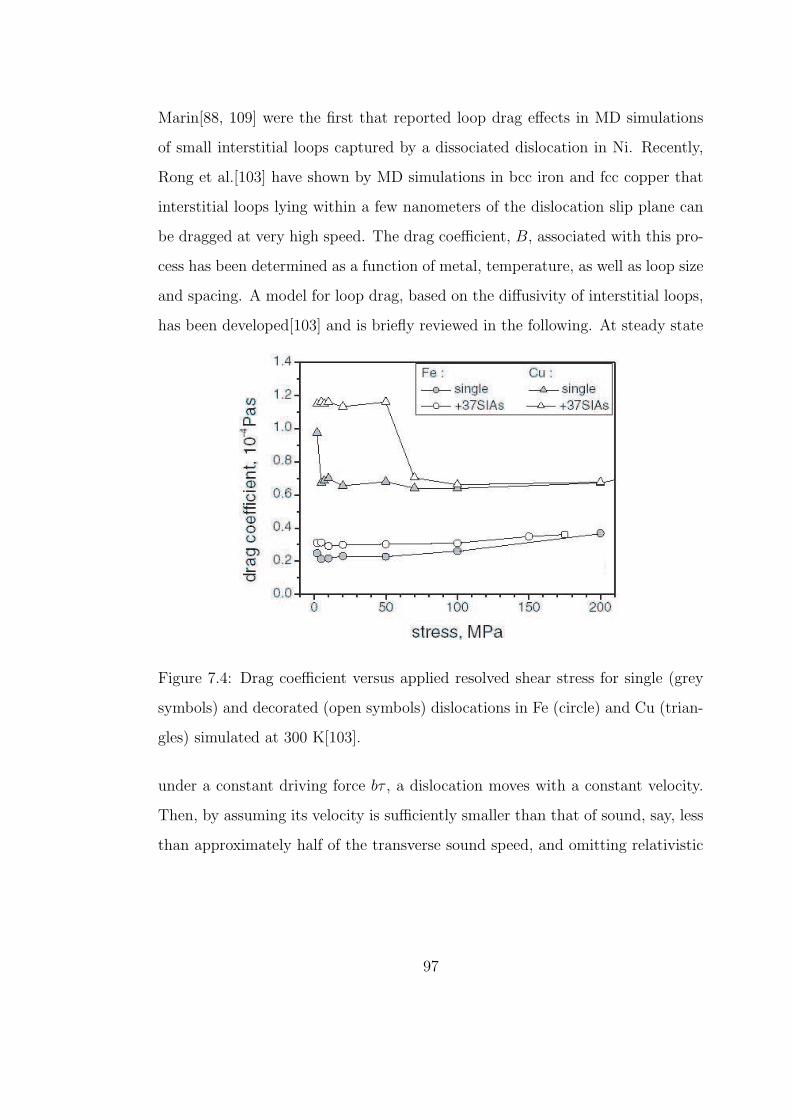
Marin[88, 109] were the first that reported loop drag effects in MD simulations
of small interstitial loops captured by a dissociated dislocation in Ni. Recently,
Rong et al.[103] have shown by MD simulations in bcc iron and fcc copper that
interstitial loops lying within a few nanometers of the dislocation slip plane can
be dragged at very high speed. The drag coefficient, B, associated with this pro-
cess has been determined as a function of metal, temperature, as well as loop size
and spacing. A model for loop drag, based on the diffusivity of interstitial loops,
has been developed[103] and is briefly reviewed in the following. At steady state
Figure 7.4: Drag coefficient versus applied resolved shear stress for single (grey
symbols) and decorated (open symbols) dislocations in Fe (circle) and Cu (trian-
gles) simulated at 300 K[103].
under a constant driving force bτ , a dislocation moves with a constant velocity.
Then, by assuming its velocity is sufficiently smaller than that of sound, say, less
than approximately half of the transverse sound speed, and omitting relativistic
97
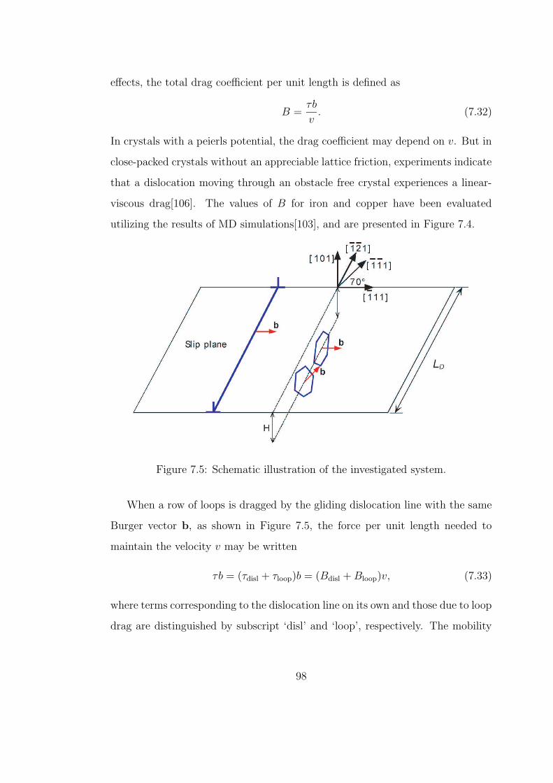
effects, the total drag coefficient per unit length is defined as
B =τb
v. (7.32)
In crystals with a peierls potential, the drag coefficient may depend on v. But in
close-packed crystals without an appreciable lattice friction, experiments indicate
that a dislocation moving through an obstacle free crystal experiences a linear-
viscous drag[106]. The values of B for iron and copper have been evaluated
utilizing the results of MD simulations[103], and are presented in Figure 7.4.
Figure 7.5: Schematic illustration of the investigated system.
When a row of loops is dragged by the gliding dislocation line with the same
Burger vector b, as shown in Figure 7.5, the force per unit length needed to
maintain the velocity v may be written
τb = (τdisl + τloop)b = (Bdisl + Bloop)v, (7.33)
where terms corresponding to the dislocation line on its own and those due to loop
drag are distinguished by subscript ‘disl’ and ‘loop’, respectively. The mobility
98
Nasr Ghoniem
Pencil
of a loop is often defined as
mloop =v
FL
=v
τloopbLD
=1
BloopLD
(7.34)
where FL is the force exerted by the dislocation line on the loop in the direction
of loop glide, and LD is the inter-loop spacing along the dislocation line. By the
Einstein mobility relation, the mobility of a diffusing loop can also be given by
mloop =D
kT(7.35)
where D is the diffusivity and k is the Boltzmann constant. For one-dimensional
diffusion, particularly, D may be written in terms of jump frequency, ωn, of a
loop of n interstitials (Equation 6.2), as[110]
D =1
2fb2ωn (7.36)
where f is the correlation factor. Hence
Bloop =1
mloopLD
=kT
DLD
=2kT
fb2ωnLD
(7.37)
f indicates a preference for a jump to be in the same direction as the previous
one and its value decreases as temperature and size increases. According to MD
simulations, values that varies from 3 to 5 are reasonable choices for loops created
in our KMC simulations for iron at room temperature. Equation 7.37 was first
proposed by Rong et al.[103] to estimate the drag coefficient for a dislocation
gliding with a row of dragged loops in decoration.
A loop can be dragged along with the moving dislocation if the force required
does not exceed the maximum, Fmax, exerted on the loop by the dislocation. This
maximum force can be evaluated in terms of isotropic elasticity theory and the
infinitesimal loop approximation, similar to what has been implemented in the
KMC simulations. Therefore, the maximum velocity, vmax, at which one might
99
Nasr Ghoniem
Pencil
expect the dislocation to break away from the ‘atmospheres’ of small loops, can
be estimated as follows
vmax =Fmax
mloop
=Fmax
BloopLD
(7.38)
For loops whose burgers vector is parallel to the glide plane of the dislocation
but not the same as the glide direction of the dislocation, for example, [111]
direction shown in Figure 7.5, they can still be dragged, but in a direction at an
angle theta to the glide direction of the dislocation, and result in a substantial
reduction in dislocation velocity at a given stress. Their contribution to B is
much greater than that of loops with the same glide direction as that of the
dislocation. Theoretically, in order to be dragged by the dislocation moving with
velocity v, the loop speed along its glide cylinder has to be v/cosθ. In addition,
the component of the driving force FL in the glide direction of the dislocation is
FLcosθ in the glide direction of the loop. Thus, FL for a given v has to be three
times larger than for a loop with the same size and distance to the dislocation
glide plane but with the same glide direction as the dislocation[103].
For the configuration shown in Figure 7.6, which is extracted from the result
of previous KMC simulations for bcc Fe irradiated to a dose level of 5.2 × 10⁻³
dpa at 300 K(Figure 6.5(b)), values of Bloop predicted by Equation 7.37, as well
as estimates of vmax obtained from Equation 7.38 for an edge dislocation to break
away from decorating loops are presented in Table 7.1. vmax that is higher than
the transverse sound velocity in bcc iron implies that the loop will be dragged
with the dislocation all the way and never be dumped.
100
Nasr Ghoniem
Pencil
Nasr Ghoniem
Pencil
Nasr Ghoniem
Pencil
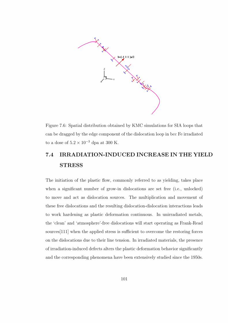
XY
Z
b=[-1 1 1 ]a/2
Figure 7.6: Spatial distribution obtained by KMC simulations for SIA loops that
can be dragged by the edge component of the dislocation loop in bcc Fe irradiated
to a dose of 5.2 × 10⁻³ dpa at 300 K.
7.4 IRRADIATION-INDUCED INCREASE IN THE YIELD
STRESS
The initiation of the plastic flow, commonly referred to as yielding, takes place
when a significant number of grow-in dislocations are set free (i.e., unlocked)
to move and act as dislocation sources. The multiplication and movement of
these free dislocations and the resulting dislocation-dislocation interactions leads
to work hardening as plastic deformation continuous. In unirradiated metals,
the ‘clean’ and ‘atmosphere’-free dislocations will start operating as Frank-Read
sources[111] when the applied stress is sufficient to overcome the restoring forces
on the dislocations due to their line tension. In irradiated materials, the presence
of irradiation-induced defects alters the plastic deformation behavior significantly
and the corresponding phenomena have been extensively studied since the 1950s.
101
It is well recognized that the defects produced by neutron irradiation must
interact with the dislocations to produce the change in the mechanical properties
of metals and alloys. Two types of interaction are involved. Some of the radiation
induced SIA clusters that are produced directly in high energy displacement cas-
cade may approach to the grow-in dislocations (dislocation sources) by thermally
activated 1-D transport, be trapped in the strain field of the dislocations and
decorate them. These SIA clusters may form a Cottrell atmosphere, and act as
barriers to the generation of dislocations (source hardening). In addition to this
type of interaction, the radiation induced defects may act as distributed barriers
to impede the motion of the dislocation after it has been released from decora-
tion clusters (friction hardening). In the first part of this section, the effect of
distributed defects on dislocation motion will be investigated; and the influence
of decoration clusters will be studied in the second part.
7.4.1 THE PLANE GLIDE RESISTANCE (FRIEDEL STATISTICS)
DUE TO VACANCIES
An vacancy-rich zone will be created in the center of a displacement spike, as men-
tioned in Section 1.1. These zones are expected to collapse into vacancy loops or
stacking fault tetrahedra (SFTs) during the cooling down phase of the cascades.
Although production of large compact planar or three-dimensional vacancy clus-
ters directly in displacement cascades have not been observed through MD simula-
tions in bcc metals, very loose complexes of vacancies in second and higher order
neighbor shells have been reported[54, 112]. The possibility that these closely
correlated vacancies might collapse into clusters over somewhat longer times has
been investigated using MC simulations. The expectation of vacancy clustering
was confirmed in the MC simulations, where many of the isolated vacancies had
102
Nasr Ghoniem
Pencil
Nasr Ghoniem
Pencil
Nasr Ghoniem
Pencil
Nasr Ghoniem
Pencil
Nasr Ghoniem
Pencil
Nasr Ghoniem
Pencil
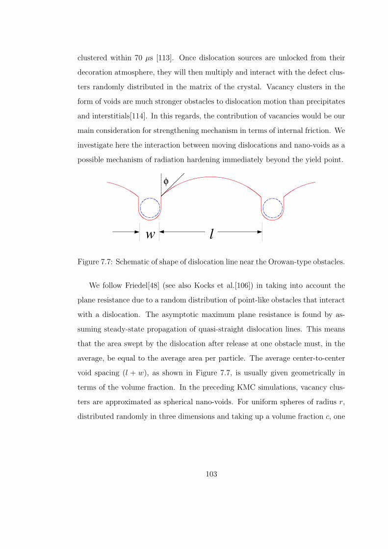
clustered within 70 µs [113]. Once dislocation sources are unlocked from their
decoration atmosphere, they will then multiply and interact with the defect clus-
ters randomly distributed in the matrix of the crystal. Vacancy clusters in the
form of voids are much stronger obstacles to dislocation motion than precipitates
and interstitials[114]. In this regards, the contribution of vacancies would be our
main consideration for strengthening mechanism in terms of internal friction. We
investigate here the interaction between moving dislocations and nano-voids as a
possible mechanism of radiation hardening immediately beyond the yield point.
lw
φ
Figure 7.7: Schematic of shape of dislocation line near the Orowan-type obstacles.
We follow Friedel[48] (see also Kocks et al.[106]) in taking into account the
plane resistance due to a random distribution of point-like obstacles that interact
with a dislocation. The asymptotic maximum plane resistance is found by as-
suming steady-state propagation of quasi-straight dislocation lines. This means
that the area swept by the dislocation after release at one obstacle must, in the
average, be equal to the average area per particle. The average center-to-center
void spacing (l + w), as shown in Figure 7.7, is usually given geometrically in
terms of the volume fraction. In the preceding KMC simulations, vacancy clus-
ters are approximated as spherical nano-voids. For uniform spheres of radius r,
distributed randomly in three dimensions and taking up a volume fraction c, one
103
Nasr Ghoniem
Pencil
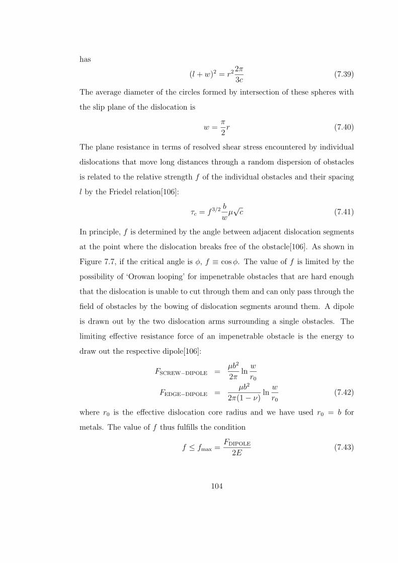
has
(l + w)2 = r2 2π
3c(7.39)
The average diameter of the circles formed by intersection of these spheres with
the slip plane of the dislocation is
w =π
2r (7.40)
The plane resistance in terms of resolved shear stress encountered by individual
dislocations that move long distances through a random dispersion of obstacles
is related to the relative strength f of the individual obstacles and their spacing
l by the Friedel relation[106]:
τc = f 3/2 b
wµ√
c (7.41)
In principle, f is determined by the angle between adjacent dislocation segments
at the point where the dislocation breaks free of the obstacle[106]. As shown in
Figure 7.7, if the critical angle is φ, f ≡ cos φ. The value of f is limited by the
possibility of ‘Orowan looping’ for impenetrable obstacles that are hard enough
that the dislocation is unable to cut through them and can only pass through the
field of obstacles by the bowing of dislocation segments around them. A dipole
is drawn out by the two dislocation arms surrounding a single obstacles. The
limiting effective resistance force of an impenetrable obstacle is the energy to
draw out the respective dipole[106]:
FSCREW−DIPOLE =µb2
2πln
w
r0
FEDGE−DIPOLE =µb2
2π(1 − ν)ln
w
r0
(7.42)
where r0 is the effective dislocation core radius and we have used r0 = b for
metals. The value of f thus fulfills the condition
f ≤ fmax =FDIPOLE
2E(7.43)
104
Nasr Ghoniem
Pencil
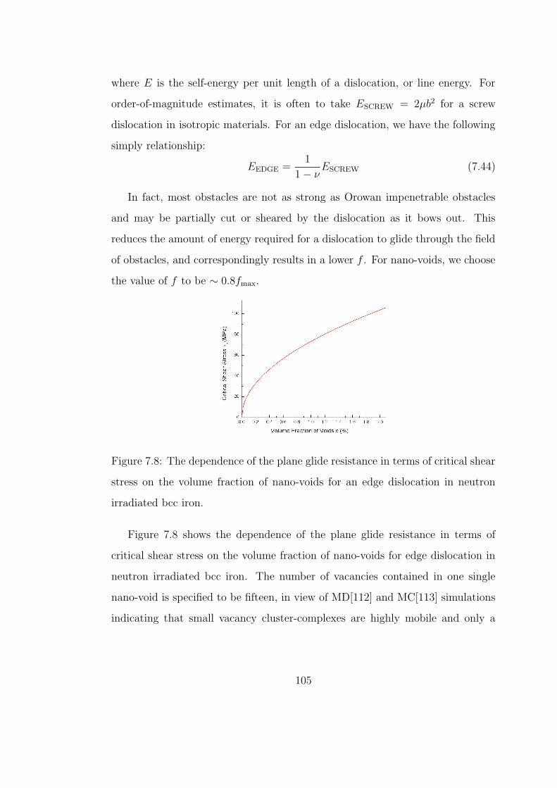
where E is the self-energy per unit length of a dislocation, or line energy. For
order-of-magnitude estimates, it is often to take ESCREW = 2µb2 for a screw
dislocation in isotropic materials. For an edge dislocation, we have the following
simply relationship:
EEDGE =1
1 − νESCREW (7.44)
In fact, most obstacles are not as strong as Orowan impenetrable obstacles
and may be partially cut or sheared by the dislocation as it bows out. This
reduces the amount of energy required for a dislocation to glide through the field
of obstacles, and correspondingly results in a lower f . For nano-voids, we choose
the value of f to be ∼ 0.8fmax.
Figure 7.8: The dependence of the plane glide resistance in terms of critical shear
stress on the volume fraction of nano-voids for an edge dislocation in neutron
irradiated bcc iron.
Figure 7.8 shows the dependence of the plane glide resistance in terms of
critical shear stress on the volume fraction of nano-voids for edge dislocation in
neutron irradiated bcc iron. The number of vacancies contained in one single
nano-void is specified to be fifteen, in view of MD[112] and MC[113] simulations
indicating that small vacancy cluster-complexes are highly mobile and only a
105
Nasr Ghoniem
Pencil
Nasr Ghoniem
Pencil
Nasr Ghoniem
Pencil
Nasr Ghoniem
Pencil
Nasr Ghoniem
Pencil
small faction (about 10%) of the stable vacancies is distributed within the range
of a loose complex of vacancies in correlated neighboring locations that may
coalesces to form one relatively large three-dimensional vacancy cluster.
When it comes to compare the critical resolved shear stress value obtained
from Equation 7.41 with a measured uniaxial yield strength, a conversion factor,
namely Taylor factor, must be applied. The average value of Taylor factor is 3.06
for equiaxed bcc and fcc metals[115].
In an effort to interpret the observed increase in the critical shear stress for
plastic deformation due to neutron irradiation, two mechanisms were proposed.
contributions to the increase of strength of the irradiated material. On the one
hand, the original dislocation structure present in the crystal will be pinned down
by the defects produced during irradiation. A clear example in neutron-irradiated
Mo single crystal is shown in Fig. 8, where dislocations are locked by small clus-
ters with a very small separation. Notice also that there is a distribution of
loops in the rest of the crystal matrix, but at a lower density and larger spacing.
Trinkaus et al. [16] have lately reviewed the conditions for this dislocation deco-
ration and arrived at the conclusion that the direct clustering of SIAs or vacancies
in a region near the dislocation cannot be due to three-dimensional diffusion and
agglomeration of single SIAs, but rather that the decoration is produced by the
accumulation of one-dimensionally migrating glissile loops, that were produced
originally in the cascades. MD simulations [14,17,18] have actually demonstrated
this one-dimensional motion. The clusters remain in a metastable state near
to the dislocation and can only be absorbed by it after a thermally activated
[16,19,20] or elastic force field-induced [21] change in Burgers vector direction.
The second contribution will come from the unlocked source dislocation that
will then multiply and interact with the distribution of defect clusters present
106
Nasr Ghoniem
Pencil
Nasr Ghoniem
Pencil
Nasr Ghoniem
Pencil
Nasr Ghoniem
Pencil
Nasr Ghoniem
Pencil
Nasr Ghoniem
Pencil
Nasr Ghoniem
Pencil
Nasr Ghoniem
Pencil
Nasr Ghoniem
Pencil
in the matrix of the crystal which are separated at a much larger distance: for
the crystal taken as an example in the above discussion the mean distance in the
matrix L = (Nd)−1/2 ∼ 280 nm, a factor of about one hundred times larger than
the value for dislocation locking. It has been shown [3,15] that the hardening
by this defect structure is well represented by the dispersed obstacle model [22],
where the increase of strength, beyond the upper yield point, compared to the
unirradiated state, is given by
∆τ = αµb(Nd)1/2, (7.45)
where α is a factor that accounts for the strength of the obstacle. It was found
[3] that in the irradiated Cu single crystals there is a linear relation between the
measured values of ∆τ and (Nd)1/2 with a resultant value of a α = 0.1−0.2, which
describes soft obstacles. It should be pointed out that these measurements were
performed in the yield region. Beyond it, as it is further discussed in Section 3.3,
the contribution from dislocation-dislocation interaction to the work hardening is
the main component of the flow stress. Furthermore, for higher dose levels, where
only a yield region at approximate constant stress level (see Fig. 7) is observed,
∆τ reflects the resistance to dislocation motion in the channels.
7.4.2 INTERACTION BETWEEN A STRAIGHT EDGE DISLO-
CATION AND SIA CLUSTER DECORATIONS
It has been shown by both experiments and computer simulations that the Frank-
Read sources are decorated by small SIA clusters during neutron irradiation.
These clusters are produced directly in the multi-displacement cascades and small
SIA clusters are extremely mobile, which have been demonstrated by MD simu-
lations (see the preceding chapters). Using PDD method, Ghoniem et al. inves-
tigated the dynamics of a expanding Frank-Read source dislocation interaction
107
Nasr Ghoniem
Pencil
Nasr Ghoniem
Pencil
Nasr Ghoniem
Pencil
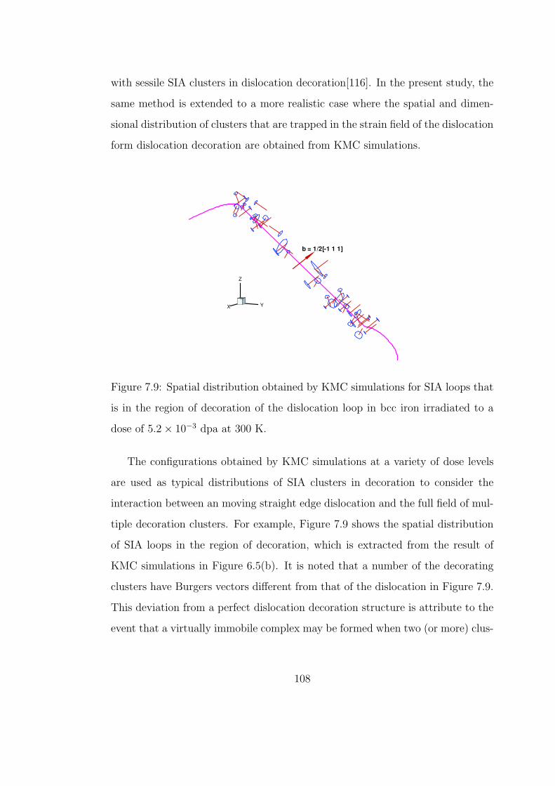
with sessile SIA clusters in dislocation decoration[116]. In the present study, the
same method is extended to a more realistic case where the spatial and dimen-
sional distribution of clusters that are trapped in the strain field of the dislocation
form dislocation decoration are obtained from KMC simulations.
X Y
Z
b = 1/2[-1 1 1]
Figure 7.9: Spatial distribution obtained by KMC simulations for SIA loops that
is in the region of decoration of the dislocation loop in bcc iron irradiated to a
dose of 5.2 × 10⁻³ dpa at 300 K.
The configurations obtained by KMC simulations at a variety of dose levels
are used as typical distributions of SIA clusters in decoration to consider the
interaction between an moving straight edge dislocation and the full field of mul-
tiple decoration clusters. For example, Figure 7.9 shows the spatial distribution
of SIA loops in the region of decoration, which is extracted from the result of
KMC simulations in Figure 6.5(b). It is noted that a number of the decorating
clusters have Burgers vectors different from that of the dislocation in Figure 7.9.
This deviation from a perfect dislocation decoration structure is attribute to the
event that a virtually immobile complex may be formed when two (or more) clus-
108
Nasr Ghoniem
Pencil
Nasr Ghoniem
Pencil
Nasr Ghoniem
Pencil
Nasr Ghoniem
Pencil
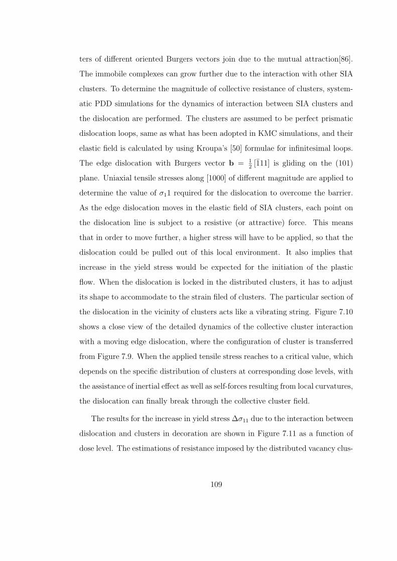
ters of different oriented Burgers vectors join due to the mutual attraction[86].
The immobile complexes can grow further due to the interaction with other SIA
clusters. To determine the magnitude of collective resistance of clusters, system-
atic PDD simulations for the dynamics of interaction between SIA clusters and
the dislocation are performed. The clusters are assumed to be perfect prismatic
dislocation loops, same as what has been adopted in KMC simulations, and their
elastic field is calculated by using Kroupa’s [50] formulae for infinitesimal loops.
The edge dislocation with Burgers vector b = 12[111] is gliding on the (101)
plane. Uniaxial tensile stresses along [1000] of different magnitude are applied to
determine the value of σ11 required for the dislocation to overcome the barrier.
As the edge dislocation moves in the elastic field of SIA clusters, each point on
the dislocation line is subject to a resistive (or attractive) force. This means
that in order to move further, a higher stress will have to be applied, so that the
dislocation could be pulled out of this local environment. It also implies that
increase in the yield stress would be expected for the initiation of the plastic
flow. When the dislocation is locked in the distributed clusters, it has to adjust
its shape to accommodate to the strain filed of clusters. The particular section of
the dislocation in the vicinity of clusters acts like a vibrating string. Figure 7.10
shows a close view of the detailed dynamics of the collective cluster interaction
with a moving edge dislocation, where the configuration of cluster is transferred
from Figure 7.9. When the applied tensile stress reaches to a critical value, which
depends on the specific distribution of clusters at corresponding dose levels, with
the assistance of inertial effect as well as self-forces resulting from local curvatures,
the dislocation can finally break through the collective cluster field.
The results for the increase in yield stress ∆σ11 due to the interaction between
dislocation and clusters in decoration are shown in Figure 7.11 as a function of
dose level. The estimations of resistance imposed by the distributed vacancy clus-
109
Nasr Ghoniem
Pencil
Nasr Ghoniem
Pencil
Nasr Ghoniem
Pencil
Nasr Ghoniem
Pencil
Nasr Ghoniem
Pencil
Nasr Ghoniem
Pencil
Nasr Ghoniem
Pencil
Nasr Ghoniem
Pencil
Nasr Ghoniem
Pencil
Nasr Ghoniem
Pencil
Nasr Ghoniem
Pencil
Nasr Ghoniem
Pencil
Nasr Ghoniem
Pencil
Nasr Ghoniem
Pencil
Nasr Ghoniem
Pencil
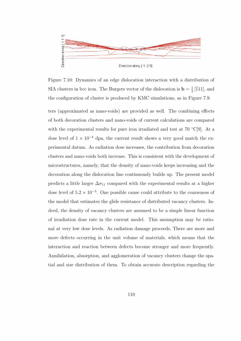
Figure 7.10: Dynamics of an edge dislocation interaction with a distribution of
SIA clusters in bcc iron. The Burgers vector of the dislocation is b = 12[111], and
the configuration of cluster is produced by KMC simulations, as in Figure 7.9.
ters (approximated as nano-voids) are provided as well. The combining effects
of both decoration clusters and nano-voids of current calculations are compared
with the experimental results for pure iron irradiated and test at 70 C[9]. At a
dose level of 1 × 10⁻⁴ dpa, the current result shows a very good match the ex-
perimental datum. As radiation dose increases, the contribution from decoration
clusters and nano-voids both increase. This is consistent with the development of
microstructures, namely, that the density of nano-voids keeps increasing and the
decoration along the dislocation line continuously builds up. The present model
predicts a little larger ∆σ11 compared with the experimental results at a higher
dose level of 5.2 × 10⁻³. One possible cause could attribute to the coarseness of
the model that estimates the glide resistance of distributed vacancy clusters. In-
deed, the density of vacancy clusters are assumed to be a simple linear function
of irradiation dose rate in the current model. This assumption may be ratio-
nal at very low dose levels. As radiation damage proceeds, There are more and
more defects occurring in the unit volume of materials, which means that the
interaction and reaction between defects become stronger and more frequently.
Annihilation, absorption, and agglomeration of vacancy clusters change the spa-
tial and size distribution of them. To obtain accurate description regarding the
110
Nasr Ghoniem
Pencil
Nasr Ghoniem
Pencil
Nasr Ghoniem
Pencil
Nasr Ghoniem
Pencil
Nasr Ghoniem
Pencil
Nasr Ghoniem
Pencil
Nasr Ghoniem
Pencil
Nasr Ghoniem
Pencil
Nasr Ghoniem
Pencil
Nasr Ghoniem
Pencil
Nasr Ghoniem
Pencil
Nasr Ghoniem
Pencil
Nasr Ghoniem
Pencil
Nasr Ghoniem
Pencil
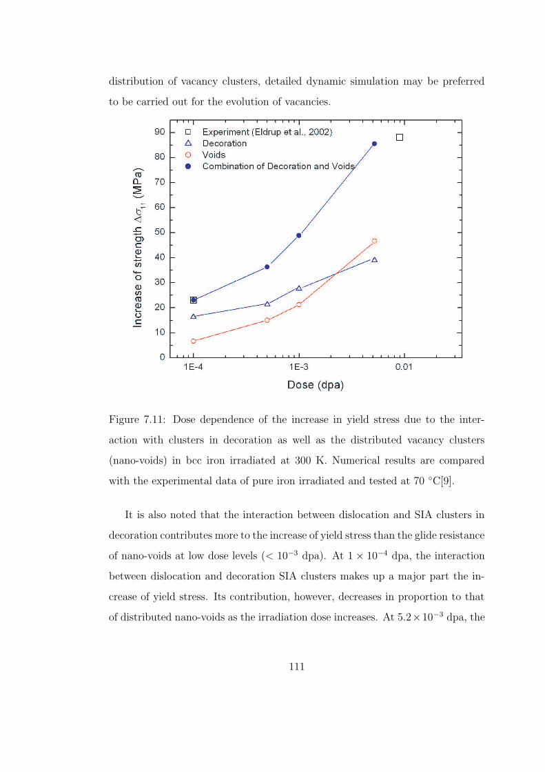
distribution of vacancy clusters, detailed dynamic simulation may be preferred
to be carried out for the evolution of vacancies.
Figure 7.11: Dose dependence of the increase in yield stress due to the inter-
action with clusters in decoration as well as the distributed vacancy clusters
(nano-voids) in bcc iron irradiated at 300 K. Numerical results are compared
with the experimental data of pure iron irradiated and tested at 70 C[9].
It is also noted that the interaction between dislocation and SIA clusters in
decoration contributes more to the increase of yield stress than the glide resistance
of nano-voids at low dose levels (< 10−3 dpa). At 1 × 10⁻⁴ dpa, the interaction
between dislocation and decoration SIA clusters makes up a major part the in-
crease of yield stress. Its contribution, however, decreases in proportion to that
of distributed nano-voids as the irradiation dose increases. At 5.2×10⁻³ dpa, the
111
Nasr Ghoniem
Pencil
Nasr Ghoniem
Pencil
Nasr Ghoniem
Pencil
Nasr Ghoniem
Pencil
Nasr Ghoniem
Pencil
Nasr Ghoniem
Pencil
Nasr Ghoniem
Pencil
Nasr Ghoniem
Pencil
Nasr Ghoniem
Pencil
Nasr Ghoniem
Pencil
Nasr Ghoniem
Pencil
Nasr Ghoniem
Pencil
increase of yield stress due to the impediment of nano-voids to dislocation motion
has exceeded that due to the SIA clusters in decoration. It implies that at high
dose levels, plane glide resistance due to distributed vacancy clusters may play a
more significant role in modifying the plastic deformation behavior of irradiated
materials than the SIA clusters in decoration region.
7.5 VELOCITY OF EDGE DISLOCATIONS IN NEUTRON-
IRRADIATED BCC IRON
Interaction of dislocations with SIA clusters in decoration region, as well as in-
terstitial clusters dragged by moving dislocations, affects glide behavior of dislo-
cations dramatically, and thereby alter the microstructure evolution and micro-
scopical plastic deformation behavior of materials. As far as the dynamics of a
dislocation is concerned, it is not only the geometrical shape that is taken by a
dislocation interacting with other defects and microstructures, but also the mo-
bility of dislocation in different scenarios. Of particular interest in this context
are the dislocation interaction with SIA cluster, the mobility of clusters and the
influence of dragging effect on dislocation velocity. In this section we present
the result of PDD simulation of dislocation velocity with taking into account
interactions between a gliding edge dislocation and decoration formed by small
interstitial clusters. The settings for the moving edge dislocation and interstitial
clusters in the current simulation are the same as those employed in Section 7.4.2
for the case at a dose of 5.2 × 10⁻³ dpa, and the drag effect discussed in Section
7.3 is applied as well.
The applied external stress as a function of time is shown in Figure 7.12. Ini-
tially, a constant uniaxial tensile stress along [100] of σ11 = 30 MPa is suddenly
112
Nasr Ghoniem
Pencil
Nasr Ghoniem
Pencil
Nasr Ghoniem
Pencil
Nasr Ghoniem
Pencil
Nasr Ghoniem
Pencil
Nasr Ghoniem
Pencil
Nasr Ghoniem
Pencil
Nasr Ghoniem
Pencil
Nasr Ghoniem
Pencil
Nasr Ghoniem
Pencil
Nasr Ghoniem
Pencil
Nasr Ghoniem
Pencil
Nasr Ghoniem
Pencil
Nasr Ghoniem
Pencil
Nasr Ghoniem
Pencil
Nasr Ghoniem
Pencil
Nasr Ghoniem
Pencil
Nasr Ghoniem
Pencil
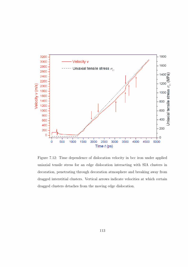
Figure 7.12: Time dependence of dislocation velocity in bcc iron under applied
uniaxial tensile stress for an edge dislocation interacting with SIA clusters in
decoration, penetrating through decoration atmosphere and breaking away from
dragged interstitial clusters. Vertical arrows indicate velocities at which certain
dragged clusters detaches from the moving edge dislocation.
113
Nasr Ghoniem
Pencil
Nasr Ghoniem
Pencil
Nasr Ghoniem
Pencil
applied and kept for 1.4 nanosecond. The stress σ11 is then gradually increased
at a constant rate of 0.5MPa/ps. The time dependence of the edge dislocation’s
velocity is presented in Figure 7.12 as well. As soon as the stress is applied, the
velocity of the edge dislocation increases from zero to a stable value of around
120 m/s within 30 ps. The dislocation motion is not affected by the strain field
of the interstitial clusters located ahead of its moving path when the distance
between them is still rather large. As the dislocation comes closer to the intersti-
tial clusters, the interaction between them keeps increasing and starts affecting
dislocation velocity. The fluctuation on the velocity-time line in Figure 7.12 indi-
cates that the interaction between the edge dislocation and the clusters is quite
intensive, and the edge dislocation vibrates back and forth like a string. Once the
dislocation line segment completely submerged into the atmosphere of interstitial
clusters, its velocity decreases to nearly zero and remains trapped by the force
field of clusters because the applied stress is not high enough to release it from
the atmosphere (see Figure 7.11 for the critical value of applied stress). When the
applied stress starts being increased and exceeds the critical value required to un-
lock the dislocation from the cluster atmosphere, velocity of the edge dislocation
begins to grow accordingly. The released dislocation is travelling with some of
the clusters in decoration, whose Burgers vectors are parallel the the glide plane
of the dislocation. When the dislocation velocity reaches a certain values vmax
presented in Table 7.1, the force exerted on the corresponding interstitial cluster
is no long able to provide the force required to make the cluster be dragged mov-
ing with the dislocation. As a result, the interstitial cluster is then discarded by
the moving dislocation. The breakaway of the dislocation from the dragged inter-
stitial clusters results in part of the resistance provided by the dragged clusters
to dislocation motion suddenly vanishing and a reduction in the effective drag
coefficient, and dislocation velocity therefore acquires a abrupt jump. The steps
114
Nasr Ghoniem
Pencil
Nasr Ghoniem
Pencil
Nasr Ghoniem
Pencil
Nasr Ghoniem
Pencil
Nasr Ghoniem
Pencil
Nasr Ghoniem
Pencil
Nasr Ghoniem
Pencil
Nasr Ghoniem
Pencil
Nasr Ghoniem
Pencil
Nasr Ghoniem
Pencil
Nasr Ghoniem
Pencil
Nasr Ghoniem
Pencil
Nasr Ghoniem
Pencil
Nasr Ghoniem
Pencil
Nasr Ghoniem
Pencil
Nasr Ghoniem
Pencil
on the velocity-time line marked by vertical arrows in Figure 7.12 clearly shows
the abrupt increases in dislocation velocity as the dislocation breaks away from
the dragged clusters. The changes in slope at different stages in the velocity-time
plot indicate reflect the reduction of the resistance force to dislocation motion
due to dragged clusters.
It is worth being pointed out that the stress-time line in Figure 7.12 resembles
the time dependence of dislocation velocity if the dislocation and the matrix ma-
terial are perfectly clean, and inertial effect of moving dislocation is completely
ignored. The results of current simulations present a more accurate and realis-
tic consideration for motion of dislocation in irradiated materials. The dynamic
behavior associated with the drastic changes in dislocation velocity may be im-
portant in investigating the microstructure evolution and plastic deformation in
irradiated materials.
When the applied stress exceeds the average glide resistance in any slip plane
in which there are mobile dislocations, large-scale slip becomes possible. We
have split the influence of radiation-induced defects on dislocation motion into
two parts, namely that due to nano-voids and that resulting from dislocation
decoration, and investigated them respectively. The impediment of distributed
nano-voids to the motion of the gliding dislocation is taken into account in terms
of the plane glide resistance. Velocity of an edge dislocation as a function of time
under different applied uniaxial tensile stresses σ11 larger than the plane glide
resistance is presented in Figure 7.13 for bcc Fe irradiated to a dose of 5.2× 10⁻³
dpa, provided dislocation interaction with interstitial clusters in decoration is
ignored.
115
Nasr Ghoniem
Pencil
Nasr Ghoniem
Pencil
Nasr Ghoniem
Pencil
Nasr Ghoniem
Pencil
Nasr Ghoniem
Pencil
Nasr Ghoniem
Pencil
Nasr Ghoniem
Pencil
Nasr Ghoniem
Pencil
Nasr Ghoniem
Pencil
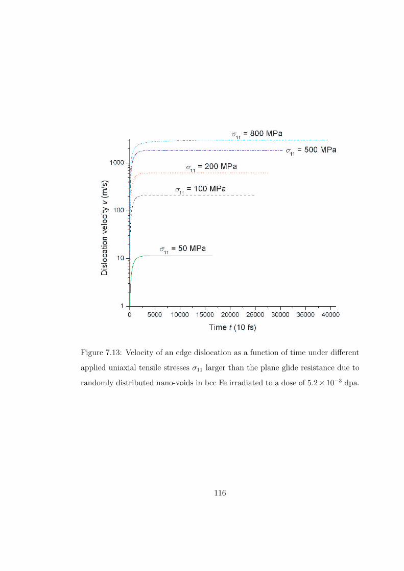
Figure 7.13: Velocity of an edge dislocation as a function of time under different
applied uniaxial tensile stresses σ11 larger than the plane glide resistance due to
randomly distributed nano-voids in bcc Fe irradiated to a dose of 5.2× 10⁻³ dpa.
116
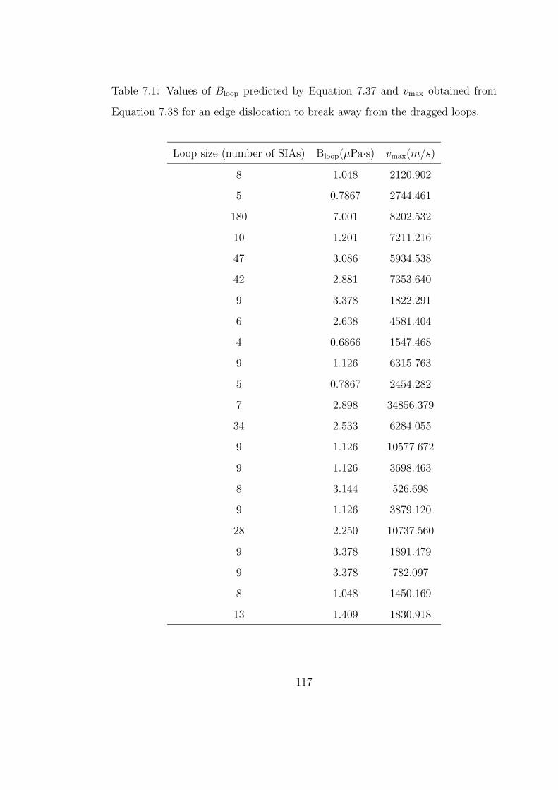
Table 7.1: Values of Bloop predicted by Equation 7.37 and vmax obtained from
Equation 7.38 for an edge dislocation to break away from the dragged loops.
Loop size (number of SIAs) Bloop(µPa·s) vmax(m/s)
8 1.048 2120.902
5 0.7867 2744.461
180 7.001 8202.532
10 1.201 7211.216
47 3.086 5934.538
42 2.881 7353.640
9 3.378 1822.291
6 2.638 4581.404
4 0.6866 1547.468
9 1.126 6315.763
5 0.7867 2454.282
7 2.898 34856.379
34 2.533 6284.055
9 1.126 10577.672
9 1.126 3698.463
8 3.144 526.698
9 1.126 3879.120
28 2.250 10737.560
9 3.378 1891.479
9 3.378 782.097
8 1.048 1450.169
13 1.409 1830.918
117
Nasr Ghoniem
Pencil
Nasr Ghoniem
Pencil
Nasr Ghoniem
Pencil
Nasr Ghoniem
Pencil
CHAPTER 8
CONCLUSIONS
Understanding and predicting mechanical performances of metals and alloys un-
der neutron irradiation conditions require a detailed understanding of both the
materials microstructure as it evolves during irradiation and the connection be-
tween microstructure features and mechanical properties. The motion of fast
thermally-activated, one-dimensionally migrating SIA clusters, and their interac-
tion with each other and dislocations result in a number of interesting microstruc-
ture features and consequently changes in mechanical behavior. An approach
to KMC simulations that incorporates the elastic interaction between various
components of the microstructure has been developed. The main purpose of
this approach is to investigate the evolution of spatial heterogeneities in the mi-
crostructure of irradiated materials. The model evolves atomic configurations by
identifying their thermally activated atomic jump events and implements a prob-
abilistic scheme for their subsequent execution. In applying the KMC method
to the investigation of radiation-induced microstructure evolution, the likelihood
that an SIA cluster migrates from one lattice site to another depends upon its lo-
cal atomic configuration which can be characterized by an activation energy and
a jump attempt frequency. The SIA cluster is approximated as an infinitesimal
prismatic dislocation loop and the interaction energy with all other neighboring
loops, vacancies and dislocations is calculated. The energy difference between
the current position and a tentative one is evaluated and utilized to modify the
118
Nasr Ghoniem
Pencil
Nasr Ghoniem
Pencil
Nasr Ghoniem
Pencil
Nasr Ghoniem
Pencil
Nasr Ghoniem
Pencil
Nasr Ghoniem
Pencil
Nasr Ghoniem
Pencil
Nasr Ghoniem
Pencil
activation energy of the corresponding jump event. The simulation first deduces
the set of jump probabilities for every allowed jump event using precalculated
activation energies and then executes jumps according to their relative proba-
bilities. After a jump is executed, time is advanced by a computational time
step determined by the residence time of the system, i.e. the reciprocal of the
sum of the jump rates for all the allowed jump events of the system. This pro-
cess is then repeated until the time between designated displacement cascades
is exhausted. A new displacement cascade is then introduced and the algorithm
iterated. By using this new approach to KMC, the interaction among defect clus-
ters and microstructures that is crucial for studying microstructure evolution and
was absent from existing KMC simulations has been integrated. The parallelized
KMC enables a realistic simulation of the evolution of radiation-induced damage.
The KMC model has been applied to the investigation of point defect segrega-
tion and damage accumulation under cascade irradiation in bcc Fe. The following
features are in agreement with experimental observations: (1) the overall sessile
SIA cluster density, its dose dependence and eventual saturation, (2) the forma-
tion of dislocation decoration, (3) the “autocatalytic” formation of SIA cluster
rafts, their Burgers vector orientation and lower mobility.
The importance of glissile SIA clusters produced in displacement cascades has
been demonstrated to play a decisive role in the irradiation-induced microstruc-
tural evolution. The 1-D motion of glissile SIA clusters and the interaction be-
tween defects and the dislocation microstructure were shown to be the main cause
for the appearance and development of decorations and rafts. At a rather low
dose around 1.0 × 10⁻³ dpa, a large portion of the initially glissile clusters are
shown to be trapped around the slip dislocation loop ( the majority of them are
distributed near the edge component) and become virtually immobile. The high
119
Nasr Ghoniem
Pencil
Nasr Ghoniem
Pencil
Nasr Ghoniem
Pencil
Nasr Ghoniem
Pencil
Nasr Ghoniem
Pencil
concentration of SIA loops around slip dislocations results in an extremely in-
homogeneous spatial distribution. the simulations quantitatively show how SIA
clusters are attracted to dislocations to decorate and lock them in place. The
present work suggests that raft formation can be achieved by prismatic glide of
glissile interstitial clusters and rotation of their Burgers vectors under the influ-
ence of internal strain fields (e.g. generated by dislocations).
The parametric dislocation dynamics method was modified by adding an ef-
fective mass term to the EOM of dislocation to take into account inertial effects
of moving dislocation, and used to investigated the increase in the yield stress due
to dislocations interaction with interstitial loops in dislocation decoration region
and distributed nanoscale voids. The mass of dislocation is evaluated in terms
of the kinetic energy of a dislocation moving at uniform velocity with analogy to
its counterpart in mechanics. Observed radiation-induced increase in the yield
stress in tensile test was investigated from two perspectives: (1) the plane glide
resistance due to distributed nano-voids, and (2) dislocation interaction with SIA
clusters in decoration region. The former effect was investigated by using Friedel
statistics for a random distribution of point-like obstacles, and the latter was
examined by performing parametric dislocation dynamics simulations. The com-
bination of the above two effects was compared with experimental measurements
and a reasonably good agreement was shown. The study in this thesis indicates
that at low damage dose levels dislocation interaction with radiation-induced in-
terstitial clusters in dislocation decoration region is the main mechanism for the
increase in yield strength, while at higher dose levels the impediment to dislo-
cation motion by randomly distributed obstacles seems to be in ascendant. The
influence of radiation-induced defect clusters on dislocation mobility has also been
investigated using dislocation dynamics simulations. Future work will focus on
the continued improvement of simulation methods and the coupling of the tech-
120
Nasr Ghoniem
Pencil
Nasr Ghoniem
Pencil
Nasr Ghoniem
Pencil
Nasr Ghoniem
Pencil
Nasr Ghoniem
Pencil
Nasr Ghoniem
Pencil
Nasr Ghoniem
Pencil
Nasr Ghoniem
Pencil
Nasr Ghoniem
Pencil
Nasr Ghoniem
Pencil
Nasr Ghoniem
Pencil
Nasr Ghoniem
Pencil
Nasr Ghoniem
Pencil
Nasr Ghoniem
Pencil
Nasr Ghoniem
Pencil
Nasr Ghoniem
Pencil
Nasr Ghoniem
Pencil
Nasr Ghoniem
Pencil
Nasr Ghoniem
Pencil
Nasr Ghoniem
Pencil
Nasr Ghoniem
Pencil
Nasr Ghoniem
Pencil
niques and analysis present in this thesis with large scale computer simulations
to predict microstructure evolution in irradiated materials.
121
References
[1] Douglas S. Billington and James H. Crawford, Jr. Radiation Damage in
Solids. Princeton University Press, Princeton, New Jersey, 1961.
[2] M. O. Hagler and M. Kristiansen. An Introduction to Controlled Ther-
monuclear Fusion. Lexington Books, Lexington, MA, 1977. p. 16.
[3] T. Kammash. Fusion Reactor Physics. Ann Arbor Science, Ann Arbor,MI, 3rd edition, 1977. p. 21 and 351.
[4] W. M. Stacey, Jr. Fusion Plasma Analysis. Wiley and Sons, New York,1981. p. 225.
[5] W. M. Stacey, Jr. Fusion: An Introduction to the Physics and Technology
of Magnetic Confinement Fusion. Wiley and Sons, New York, 1984. p. 88.
[6] D. J. Rose and M. Clark, Jr. Plasma and Controlled Fusion. MIT Press,Cambridge, MA, 1961. p. 228.
[7] L. Spitzer, Jr. Physics of Fully Ionized Gases. Interscience, New York,1956. p. 88.
[8] B. N. Singh, D. J. Edwards, and P. Toft. Effects of neutron irradiation onmechanical properties and microstructures of dispersion and precipitationhardened copper alloys. J. Nucl. Mater., 238(2-3):244–259, 1996.
[9] M. Eldrup, B. N. Singh, S. J. Zinkle, T. S. Byun, and K. Farrell. Dosedependence of defect accumulation in neutron irradiated copper and iron.J. Nucl. Mater., 307-311:912–917, 2002.
[10] A. W. McReynolds, W. Augustiniak, M. McKewon, and D. B. Rosenblatt.Neutron irradiation effects in Cu and Al at 80 K. Phys. Rev., 98(2):418–425, 1955.
[11] T. H. Blewitt, R. R. Coltman, R. E. Jamison, and J. K. Redman. Radiationhardening of copper single crystals. J. Nucl. Mater., 2(4):277–298, 1960.
[12] B. N. Singh, A. J. E. Foreman, and H. Trinkaus. Radiation hardeningrevisited: role of intracascade clustering. J. Nucl. Mater., 249(2-3):103–115, 1997.
[13] B.N. Singh, A. Horsewell, and P. Toft. Effects of neutron irradiation onmicrostructure and mechanical properties of pure iron. J. Nucl. Mater.,271-272:97–101, 1999.
122
[14] M. Victoria, N. Baluc, C. Bailat, Y. Dai, M. I. Luppo, R. Schaublin, andB. N. Singh. The microstructure and associated tensile properties of irra-diated fcc and bcc metals. J. Nucl. Mater., 276:ii4–122, 2000.
[15] D. J. Bacon, F. Gao, and Osetsky Y. N. The primary damage state inFCC, BCC and HCP metals as seen in molecular dynamics simulations.J. Nucl. Mater., 276(2):1–12, 2000.
[16] B. von Guerard, D. Grasse, and J. Peisl. Structure of defect cascades infast neutron irradiated alumium by diffuse X-ray scattering. Phys. Rev.
Lett., 44(4):262–265, 1980.
[17] D. Grasse, B. von Guerard, and J. Peisl. fast neutron irradiation of molyb-denum studied by diffuse X-ray scattering. J. Nucl. Mater., 120(2-3):304–308, 1984.
[18] R. Rauch, J. Peisl, A. Schmalzbauer, and G. Wallner. Correlation of inter-stitials within defect cascades in Al(Zn) and Cu observed by diffuse X-rayscattering. J. Nucl. Mater., 168(1-2):101–108, 1989.
[19] T. Diaz de la Rubia and M.W. Guinan. New mechanism of defect pro-duction in metals: a molecular-dynamics study of interstitial-dislocation-loop formation in high-energy displacement cascades. Phys. Rev. Lett.,66(21):2766, 1991.
[20] A. J. E. Foreman, C. A. English, and W. J. Phythian. Molecular dynamicscalculations of displacement threshold energies and replacement collisionsequences in copper using a many body potential. Phil. Mag. A, 66(5):655–669, 1992.
[21] A. J. E. Foreman, C. A. English, and W. J. Phythian. The moleculardynamics simulation of irradiation damage cascades in copper using a manybody potential. Phil. Mag. A, 66(5):671–695, 1992.
[22] A. F. Calder and D.J. Bacon. A molecular dynamics study of displacementcascades in Alpha-iron. J. Nucl. Mater., 207:25–45, 1993.
[23] W. J. Phythian, R. E. Stoller, A. J. E. Foreman, A. F. Calder, and D. J. Ba-con. A comparison of displacement cascades in copper and iron by molec-ular dynamics and its application to microstructural evolution. J. Nucl.
Mater., 223(3):245, 1995.
[24] R. E. Stoller, G. R. Odette, and B. D. Wirth. Primary damage formationin bcc iron. J. Nucl. Mater., 251:49–60, 1997.
123
[25] Y. N. Osetsky, M. Victoria, A. Serra, S. I. Golubov, and V. Priego. Com-puter simulation of vacancy and interstitial clusters in bcc and fcc metals.J. Nucl. Mater., 251:34–48, 1997.
[26] N. Soneda and T. Diaz de la Rubia. Defect production, annealing kineticand damage evolution in α-fe: an atomic-scale computer simulation. Philos.
Mag. A, 78(5):995–1019, 1998.
[27] J. L. Brimhall and B. Mastel. Neutron irradiated molybdenum-relationshipof microstructure to irradiation temperature. Radiat. Effects, 3:203–215,1970.
[28] J.O. Stiegler and E.E. Bloom. Void formation in irradiated nickel 270. Rad.
Eff., 8(1-2):33, 1971.
[29] J. Bently, B. L. Eyre, and M. H. Loretto. High temperature neutron ir-radiation damage in molybdenum. In Fundamental Aspects of Radiation
Damage in Metals, pages 925–931, Gatlinburg, TN, 1975. US-ERDA Con-ference 751006.
[30] H. Trinkaus, B. N. Singh, and A. J. E. Foreman. Mechanisms for decorationof dislocations by small dislocation loops under cascade damage conditions.J. Nucl. Mater., 249(2-3):91–102, 1997.
[31] A. J. E. Foreman and J. D. Eshelby. Atomic energy research establishmentreport. Technical Report R4170, 1962.
[32] R. S. Barnes. The migration of large clusters of point defects in irradiatedmaterials. J. Phys. Soc. Japan, 18, Suppl. III:305–311, 1963.
[33] B. L. Eyre, D. M. Maher, and A. F. Bartlett. Neutron irradiation damagein molybdenum part v. mechanisms of vacancy and interstitial loop growthduring post-irradiation annealing. Phil. Mag. A, 24:767–797, 1971.
[34] V. K. Sikka and J. Moteff. Damage in neutron-irradiated molybdenum: (I). characterization of as-irradiated microstructure. J. Nucl. Mater.,54:325–345, 1974.
[35] J. H. Evans. Void swelling and irradiation-induced void shrinkage in neu-tron irradiated molybdenum and TZM. J. Nucl. Mater., 88:31–41, 1980.
[36] K. Yamakawa and Y. Shimomura. Defects in fission-neutron irradiated Moat high temperature in the JOYO reactor. J. Nucl. Mater., 155-157:1211–1216, 1988.
124
[37] B. N. Singh, J. H. Evans, A. Horsewell, P. Toft, and D. J. Edwards. Mi-crostructure and mechanical-behavior of TZM and Mo-5-percent Re Alloysirradiated with fission neutrons. J. Nucl. Mater., 223(2):95–102, 1995.
[38] B. N. Singh, J. H. Evans, A. Horsewell, P. Toft, and G. V. Muller. Ef-fects of neutron irradiation on microstructure and deformation behaviourof mono- and polycrystalline molybdenum and its alloys. J. Nucl. Mater.,258-263:865–872, 1998.
[39] A. H. Cottrell. Dislocations and Plastic Flow in Crystals. Oxford Univer-sity Press, London, 1953.
[40] M. Kiritani. Point defect processes in the defect structure developmentfrom cascade damage. Mater. Sci. Forum, 15-18:1023–1045, 1987.
[41] S. Kojima, T. Yoshiie, and M. Kiritani. Defect structure evolution fromcascade damage in14 mev neutron irradiated nickel and nickel alloys. J.
Nucl. Mater., 155-157:1249–1253, 1988.
[42] Y. Satoh, I. Ishida, T. Yoshiie, and M. Kiritani. Defect structure develop-ment in14 mev neutron irradiated copper and copper dilute alloys. J. Nucl.
Mater., 155-157:443–448, 1988.
[43] C. H. Woo and B. N. Singh. Production bias due to clustering of pointdefects in irradiation-induced cascades. Phil. Mag. A, 65(4):889–912, 1992.
[44] M. J. Makin. Long-range forces between dislocation loops + dislocations.Phil. Mag., 10:695, 1964.
[45] A. K. Seeger. On the theory of radiation damage and radiation hardening.In Proceedings of The Second United Nations International Conference on
The Peaceful Uses of Atomic Energy, volume 6, pages 250–273, Geneva,September 1958. United Nations, New York.
[46] E. Orowan. In Symposium on Internal Stresses in Metals and Alloys, page451. Institute of Metals, London, 1948.
[47] P. M. Kelly. Progress report on recent advances in physical metallurgy.iii. the quantitative relationship between microstructure and properties intwo-phase alloys. Int. Metall. Rev., 18:31–36, 1973.
[48] J. Friedel. Dislocations. Addison-Wesley, Cambridge, MA, 1964.
[49] F. Kroupa and P. B. Hirsch. Discuss. Faraday Soc., 38:49, 1964.
125
[50] F. Kroupa. Dislocation loops. In B. Gruber, editor, Theory of Crystal
Defects, pages 275–316, New York, 1966. Academic Press.
[51] S. J. Zinkle and Y. Matsukawa. Observation and analysis of defect clusterproduction and interactions with dislocations. J. Nucl. Mater., 329-333:88–96, 2004.
[52] J. Huang and N. M. Ghoniem. the dynamics of dislocation intercation withsessile self-interstitial atom (SIA) defect clusters atomospheres. J. Comp.
Mater. Sci., 23:225–234, 2002.
[53] T. Diaz de la Rubia. Irradiation-induced defect production in elementalmetals and semiconductors: a review of recent molecular dynamics studies.A. Rev. Mater. Sci., 26:613–649, 1996.
[54] Y. N. Osetsky, D. J. Bacon, B. N. Singh, and B. D. Wirth. Atomistic studyof the generation, interaction, accumulation and annihilation of cascade-induced defect clusters. J. Nucl. Mater., 307-311:852–861, 2002.
[55] D.G. Doran. Computer simulation of displacement spike annealing. Rad.
Eff., 2(4):249, 1970.
[56] J.R. Beeler. Radiation Effects Computer Experiments. North-Holland, Am-sterdam, 1983.
[57] H.L. Heinisch. Simulating the production of free defects in irradiated met-als. Nucl. Instrum. & Meth. in Phys. Res. B, 102(1-4):47, 1995.
[58] H.L. Heinisch and B.N. Singh. Stochastic annealing simulation of differ-ential defect production in high energy cascades. J. Nucl. Mater., 232(2-3):206, 1996.
[59] M. Jaraiz, G.H. Gilmer, J.M. Poate, and T.D. de la Rubia. Atomisticcalculations of ion implantation in si: Point defect and transient enhanceddiffusion phenomena. Appl. Phys. Lett., 68(3):409, 1996.
[60] N. Metropolis, A.W. Rosenbluth, M.N. Rosenbluth, A.H. Teller, andE. Teller. Equation of state calculation by fast computing machines. J.
Chem. Phys., 21:1087, 1953.
[61] A. B. Bortz, M. H. Kalos, and J. L. Lebowitz. A new algorithm for montecarlo simulation of ising spin systems. J. Comput. Phys, 17(1):10, 1975.
[62] H. Metiu, Y.-T. Lu, and Z. Zhang. Epitaxial-growth and the art ofcomputer-simulations. Science, 255(5048):1088, 1992.
126
[63] A.F. Voter and J.D. Doll. Dynamical corrections to transition state theoryfor multistate systems: Surface self-diffusion in the rare-event regime. J.
Chem. Phys., 82:80, 1985.
[64] Y.-T. Lu, P. Petroff, and H. Metiu. Growth-kinetics simulation of theal-ga self-organization on (100) gaas vicinal surfaces. Appl. Phys. Lett.,57(25):2683, 1990.
[65] H. C. Kang and W. H. Weinberg. Kinetics of precursor-mediated orderingof two-dimensional domains. Phys. Rev. B, 38(16B):11543, 1988.
[66] C. C. Battaile and D. J. Srolovitz. A kinetic monte carlo method for theatomic-scale simulation of chemical vapor deposition: application to dia-mond. J. Appl. Phys., 82(12):6293, 1997.
[67] R. Siems. Phys. Stat. Sol., 30:645, 1968.
[68] R. Bullough and J.R. Hardy. Phil. Mag., 17:833, 1968.
[69] C.S. Hartley and R. Bullough. On the description of crystal defects bypoint-force arrays. J. Appl. Phys., 48:4557, 1977.
[70] Kroner E. Phys. kondens. Materie., 2:262, 1964.
[71] C. Teodosiu. Elastic Models of Crystal Defects. Editura Academiei, Bu-curesti; Springer-Verlag, New York, 1982.
[72] P. Ballone, W. Andreoni, R. Car, and M. Parrinello. Equilibrium structuresand finite temperature properties of silicon microclusters from ab initiomolecular-dynamics calculations. Phys. Rev. Lett., 60(4):271, 1988.
[73] Yu. N. Osetsky, D. J. Bacon, A. Serra, B. N. Singh, and S. I. Golubov.Stability and mobility of defect clusters and dislocation loops in metals. J.
Nucl. Mater., 276:65–77, 2000.
[74] H.L. Heinisch, B.N. Singh, and T. Diaz de la Rubia. Calibrating a multi-model approach to defect production in high energy collision cascades. J.
Nucl. Mater., 212-215:127, 1994.
[75] M. J. Caturla, N. Soneda, E. Alonso, B. D. Wirth, T. Diaz de la Rubia,and J. M. Perlado. Comparative study of radiation damage accumulationin cu and fe. J. Nucl. Mater., 276:13, 2000.
[76] N. M. Ghoniem. Curved parametric segments for the stress field of 3-d dislocation loops. Transactions of the ASME, J. Eng. Mater. Tech.,121(2):136, 1999.
127
[77] N. M. Ghoniem and L. Z. Sun. Fast-sum method for the elastic field ofthree-dimensional dislocation ensembles. Phys. Rev. B, 60(1):128, 1999.
[78] N. M. Ghoniem, B. N. Singh, L. Z. Sun, and T. Diaz de la Rubia. Interac-tion and accumulation of glissile defect clusters near dislocations. J. Nucl.
Mater., 276:166–177, 2000.
[79] J.D. Eshelby. The determination of the elastic field of an ellipsoidal inclu-sion, and related problems. Proc. Roy. Soc. Lond. A, 241:376, 1957.
[80] H. L. Heinisch and B. N. Singh. Stochastic annealing simulation of intra-cascade defect interactions. J. Nucl. Mater., 251:77–85, 1997.
[81] T. Diaz de la Rubia and M. W. Guinan. New mechanism of defect pro-duction in metals: a molecular-dynamics study of interstitial-dislocation-loop formation in high-energy displacement cascades. Phys. Rev. Lett.,66(21):2766–69, 1991.
[82] H.L. Heinisch. Computer simulation of high energy displacement cascades.Radiat. Eff. Def. Solids, 113:53, 1990.
[83] D.J. Bacon and T. Diaz de la Rubia. Molecular dynamics computer simu-lations of displacement cascades in metals. J. Nucl. Mater., 216:275, 1994.
[84] N. Soneda and Diaz de la Rubia. Migration kinetics of the self-interstitialatom and its clusters in bcc Fe. Phil. Mag. A, 81(2):331–343, 2001.
[85] R. E. Stoller. priviate communication, 2002.
[86] Yu. N. Osetsky, A. Serra, and V. Priego. Interactions between obile dislo-cation loops in Cu and α-Fe. J. Nucl. Mater., 276:202–212, 2000.
[87] D. Rodney and R. Phillips. Structure and strength of dislocation junctions:an atomic level analysis. Phys. Rev. Lett., 82(8):1704, 1999.
[88] D. Rodney and G. Martin. Dislocation pinning by glissile interstitial loopsin a nickel crystal: A molecular-dynamics study. Phys. Rev. B, 61(13):8714–8725, 2000.
[89] G. J. Ackland, D. J. Bacon, A. F. Calder, and T. Harry. Computer sim-ulation of point defect properties in dilute fe-cu alloy using a many-bodyinteratomic potential. Phil. Mag. A, 75(3):713–732, 1987.
[90] H. Trinkaus, B.N. Singh, and A.J.E. Foreman. Impact of glissile interstitialloop production in cascades on defect accumulation in the transient. J.
Nucl. Mater., 206(2-3):200, 1993.
128
[91] F. Gao, G. Henkelman, W. L. Weber, L. R. Corrales, and H. Jonsson.Finding possible transition states of defects in silicon-carbide and alpha-iron using the dimer method. Nucl. Instr. and Meth. B, 202:1–7, 2003.
[92] B. N. Singh and S. J. Zinkle. Defect accumulation in pure fcc metals in thetransient regime: a review. J. Nucl. Mater., 206:212–229, 1993.
[93] C. Depres, C. F. Robertson, and M. C. Fivel. Low-strain fatigue in 316lsteel surface grains: a three dimensional discrete dislocation dynamics mod-elling of the early cycles. part-1: Dislocation microstructures and mechan-ical behaviour. Phil. Mag. A, 84(22):2257, 2004.
[94] Hussein M. Zbib and T.D. Rubia. A multiscale model of plasticity: Pat-terning and localization. Society of Materials Science of Japan, A:341,2001.
[95] Z. Q. Wang, R. J. McCabe, N. M. Ghoniem, R. Lesar, A. Misra, andT. E. Mitchell. Dislocation motion in thin cu foils: Comparison betweencomputer simulation and experiment. Acta. Materialia, 52(6):1535–1542,2004.
[96] Yu.N. Osetsky, A. Serra, B.N. Singh, and S.I. Golubov. Structure andproperties of clusters of self-interstitial atoms in fcc copper and bcc iron.Phil. Mag. A, 80(9):213, 2000.
[97] N. de Diego, Y. N. Osetsky, and D. J. Bacon. Mobility of interstitial clustersin alpha-zirconium. Metall. Mater. Trans. A, 33A(3A):783–789, 2002.
[98] M. Wen, N. M. Ghoniem, and B. N. Singh. Dislocation decoration and raftformation in irradiated materials. Phil. Mag. A, 85(22):2561–2580, 2005.
[99] B. N. Singh, D. J. Edwards, S. Tahtinen, P. Moikanen, P. Jacquet, andJ. Dekyser. Final report on in-reactor tensile tests on ofhc-copper andcucrzr alloy. Technical Report Risø-R-1481(EN), Risø National Laboratory,Roskilde, Denmark, October 2004.
[100] Y. N. Osetsky, D. J. Bacon, Rong. Z., and B. N. Singh. Dynamic propertiesof edge dislocations decorated by interstitial loops in α-iron and copper.Phil. Mag. Letters, 84(11):745–754, 2004.
[101] T. Diaz de la Rubia, H. M. Zbib, T. A. Khraishi, B. D. Wirth, M. Victoria,and M. J. Caturla. Multiscale modelling of plastic flow localization inirradiated materials. Nature, 406(24):871–874, 2000.
129
[102] N.M. Ghoniem, S.-H. Tong, and L.Z. Sun. Parametric dislocation dy-namics: A thermodynamics-based approach to investigations of mesoscopicplastic deformation. Phys. Rev. B, 61(2):913, 2000.
[103] Z. Rong, Y. N. Osetsky, and D. J. Bacon. A model for the dynamics ofloop drag by a gliding dislocation. Phil. Mag. A, 85(14):1473–1493, 2005.
[104] N.M. Ghoniem, J. Huang, and Z. Wang. A new covariant-contravariant vec-tor forms for the elastic field of parametric dislocations in isotropic crystals.Phil. Mag. Lett., 82(2):55, 2002.
[105] J.P. Hirth and J. Lothe. Theory of Dislocations. Wiley, New York, 2ndedition, 1982.
[106] U. F. Kocks, A. S. Argon, and M. F. Ashby. Thermodynamics and Kinetics
of Slip, volume 19 of Progress in Materials Science. Pergamon Press Inc.,New York, 1st edition, 1975.
[107] F. C. Frank. On the equations of motion of crystal dislocations. Proc.
Phys. Soc. A, 62:131–134, 1949.
[108] J. Weertman. High velocity dislocations. In P. G. Shewmon and V. F. Za-ckay, editors, Response Of Metals To High Velocity Deformation, volume 9,pages 205–247. Interscience Publishers: New York, 1961.
[109] D. Rodney and G. Martin. Dislocation pinning by small interstitial loops:A molecular dynamics study. Phys. Rev. Lett., 82(16):3272–3275, 1999.
[110] Y. N. Osetsky, D. J. Bacon, A. Serra, S. I. Bachu, and S. I. Golubov. One-dimensional atomic transport by clusters of self-interstitial atoms in ironand copper. Phil. Mag. A, 83(1):61–91, 2003.
[111] F. C. Frank and W. T. Read. Multiplication processes for slow movingdislocations. Phys. Rev., 79(4):722–723, 1950.
[112] R. E. Stoller. The role of cascade energy and temperature in primary defectformation in iron. J. Nucl. Mater., 276:22–32, 2000.
[113] B. D. Wirth and G. R. Odette. Kinetic lattice monte carlo simulations ofcascade aging in iron and dilute iron-copper alloys. In V. V. Bulatov, T. D.de la Rubia, P. Phillips, E. Kaxiras, and N. M. Ghoniem, editors, MRS
Symposium Proceedings on Multiscale Modeling of Materials, volume 538,pages 211–216, Warrendale, PA, 1999. Materials Research Society.
130
[114] Y. N. Osetsky, D. J. Bacon, and V. Mohles. Atomic modelling of strength-ening mechanisms due to voids and copper precipitates in α-iron. Phil.
Mag. A, 83(31-34):3623–3641, 2003.
[115] R. E. Stoller and S. J. Zinkle. On the relationship between uniaxial yieldstrength and resolved shear stress in polycrystalline materials. J. Nucl.
Mater., 283-287:349–352, 2000.
[116] N.M. Ghoniem, S.-H. Tong, B.N. Singh, and L.Z. Sun. On dislocation in-teraction with radiation-induced defect clusters and plastic flow localizationin fcc metals. Philos. Mag. A, 81(11):2743, 2001.
131