Ken Andersen Instruments Division Head Science Directorate Fixing the Accelerator Time Structure ESS...
18
Ken Andersen Instruments Division Head Science Directorate Fixing the Accelerator Time Structure ESS Science Advisory Committee Lund 2010-11-04
-
Upload
gwenda-foster -
Category
Documents
-
view
217 -
download
0
Transcript of Ken Andersen Instruments Division Head Science Directorate Fixing the Accelerator Time Structure ESS...
Ken Andersen
Instruments Division Head
Science Directorate
Fixing the Accelerator Time Structure
ESS Science Advisory Committee
Lund 2010-11-04

Accelerator Time Structure
• Reference parameters:
• Pulse length τ=2ms
• Repetition period T=60ms
• Time-integrated power =5MW
• Effect on the accelerator
• What are the basic technical limits to high power?
• Risk/performance balance
• What is our envisaged upgrade path?
• F.Mezei with ESS accelerator team
• Effect on the instruments
• Choose reasonable instrument suite
• Evaluate their performance as a function of time structure
• K.Lefmann with Copenhagen McStas team
• Time structure needs to be fixed by March 2011
Power calculation
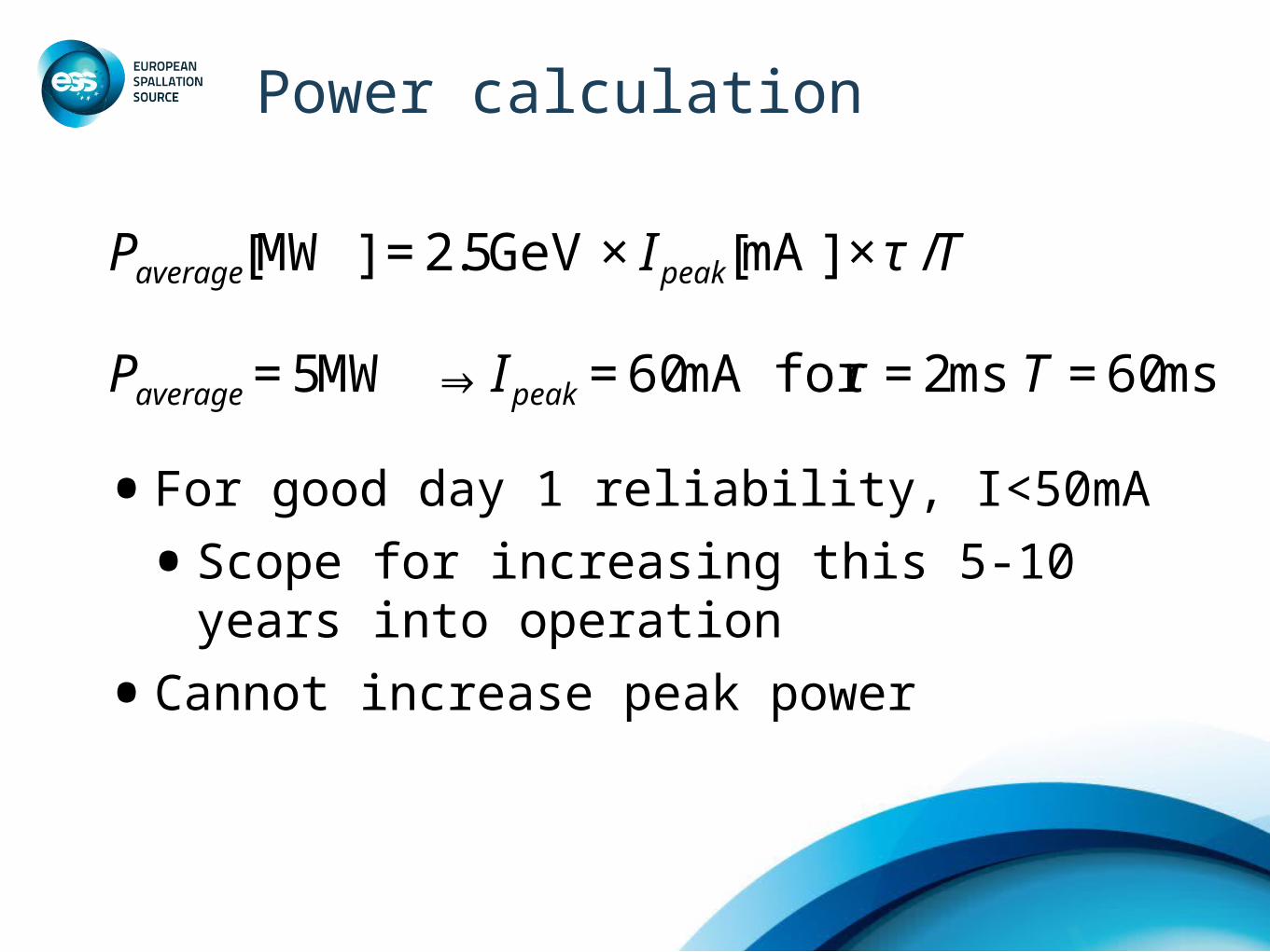
•For good day 1 reliability, I<50mA
•Scope for increasing this 5-10 years into operation
•Cannot increase peak power
€
Paverage MW[ ] = 2.5GeV × Ipeak mA[ ] × τ /T
€
Paverage = 5MW ⇒ Ipeak = 60mA for τ = 2ms T = 60ms

Shorten pulse length and T
Cold Moderator λ=4Å
• Peak flux roughly constant for τ>1ms• Loss in Time-average flux is faster than linear • Loss of plateau region
feasible
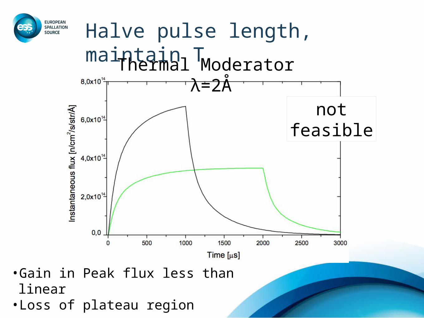
Halve pulse length, maintain T
Thermal Moderator λ=2Å
not feasible
•Gain in Peak flux less than linear• Loss of plateau region

Accelerator boundary conditions
•With 5MW and 50mA as boundary conditions:
•no scope for reducing pulse length
•no scope for reducing rep rate
•How hard should we push to go beyond those boundary conditions?
•depends on impact on accelerator reliability and on instrument performance
€
Paverage MW[ ] = 2.5GeV × Ipeak mA[ ] × τ /T
€
Paverage = 5MW ⇒ Ipeak = 60mA for τ = 2ms T = 60ms
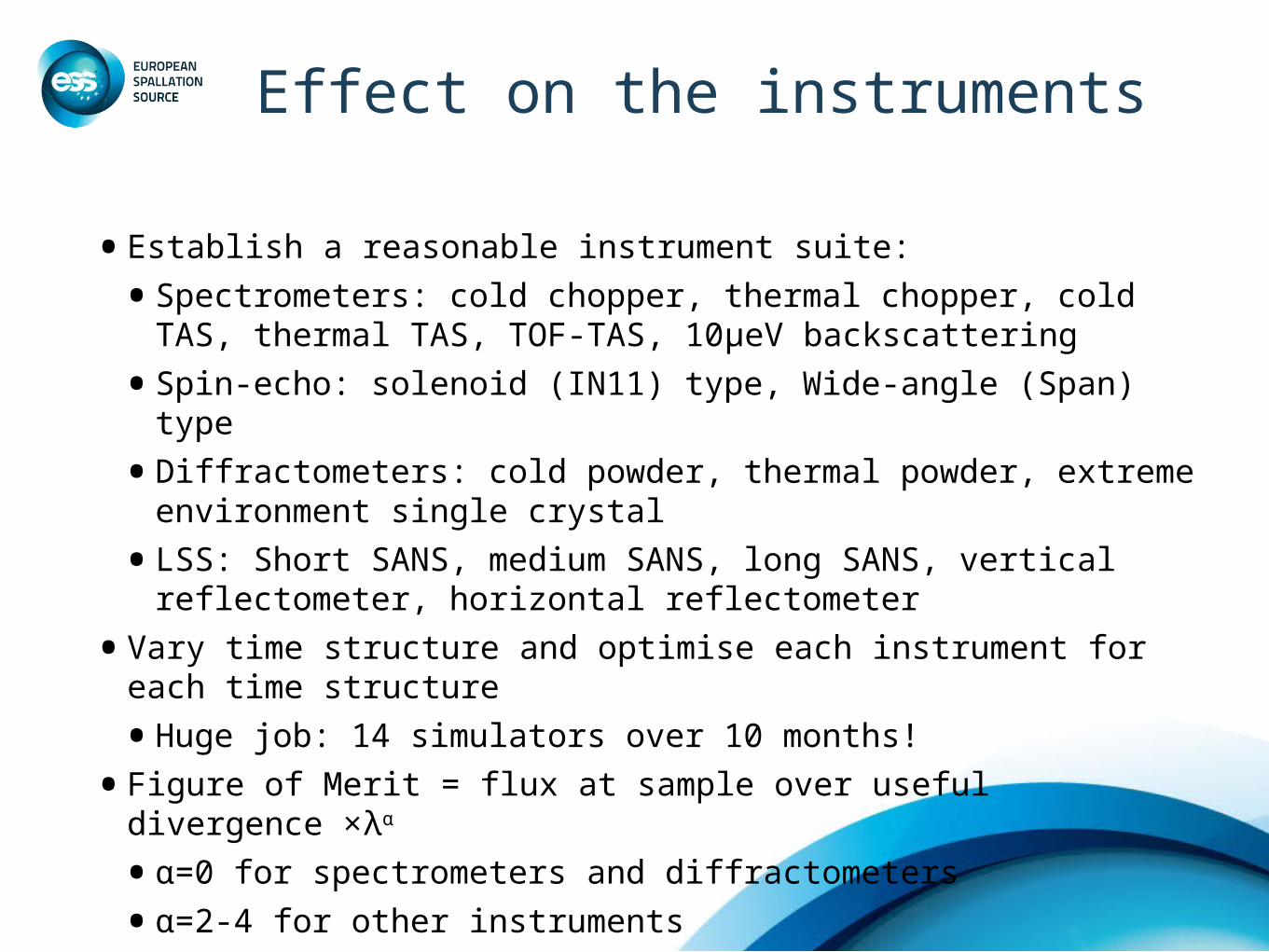
Effect on the instruments
• Establish a reasonable instrument suite:
• Spectrometers: cold chopper, thermal chopper, cold TAS, thermal TAS, TOF-TAS, 10μeV backscattering
• Spin-echo: solenoid (IN11) type, Wide-angle (Span) type
• Diffractometers: cold powder, thermal powder, extreme environment single crystal
• LSS: Short SANS, medium SANS, long SANS, vertical reflectometer, horizontal reflectometer
• Vary time structure and optimise each instrument for each time structure
• Huge job: 14 simulators over 10 months!
• Figure of Merit = flux at sample over useful divergence ×λα
• α=0 for spectrometers and diffractometers
• α=2-4 for other instruments
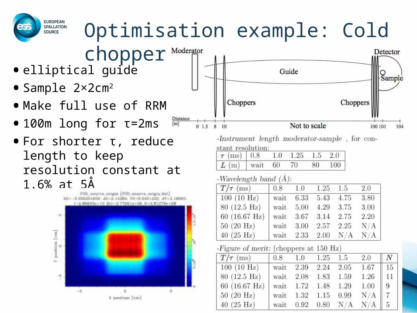
Optimisation example: Cold chopper
• elliptical guide
• Sample 2×2cm2
• Make full use of RRM
• 100m long for τ=2ms
• For shorter τ, reduce length to keep resolution constant at 1.6% at 5Å

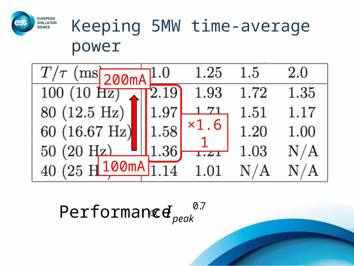
Keeping 5MW time-average power

Keeping 5MW time-average power
60mA
120mA
×1.58

Keeping 5MW time-average power
100mA
×1.61
200mA
Keeping 5MW time-average power
100mA
×1.61
200mA
€
Performance ∝ Ipeak0.7
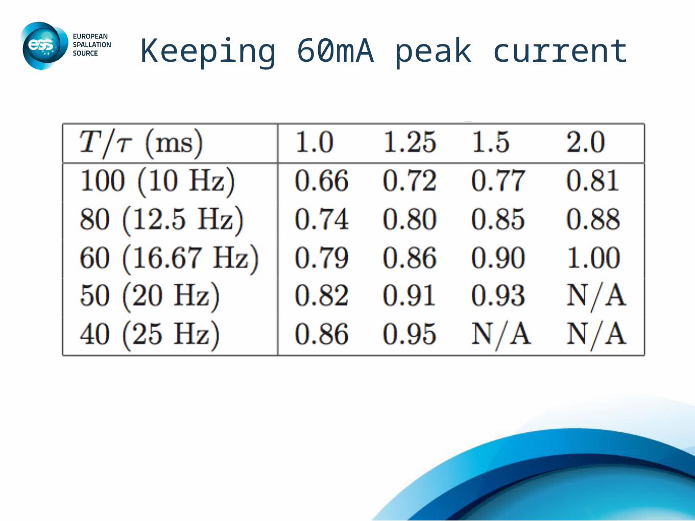
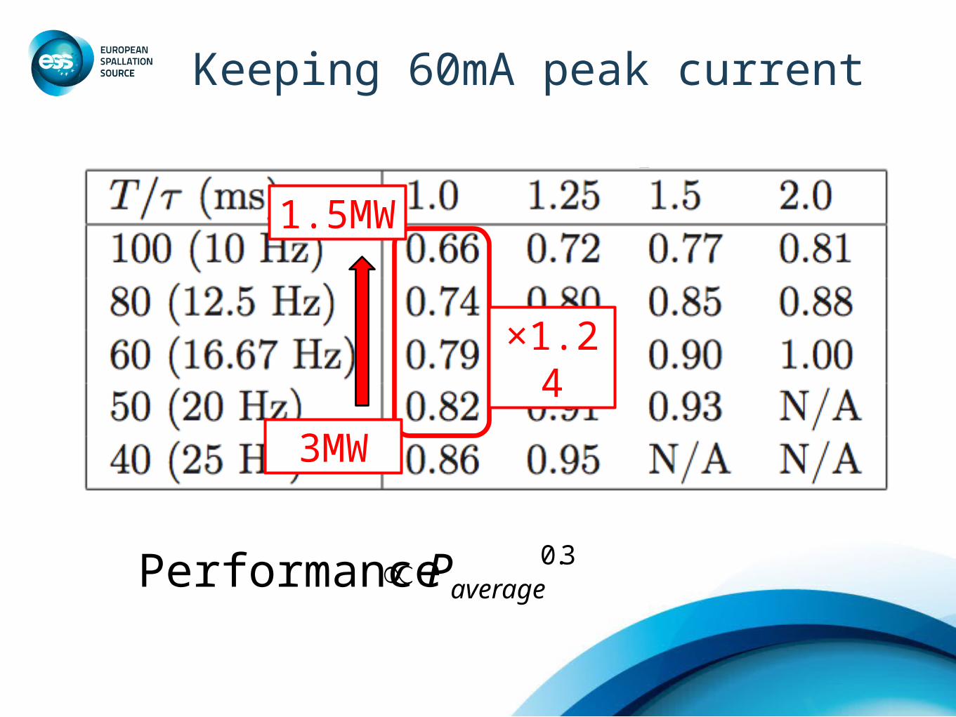
Keeping 60mA peak current
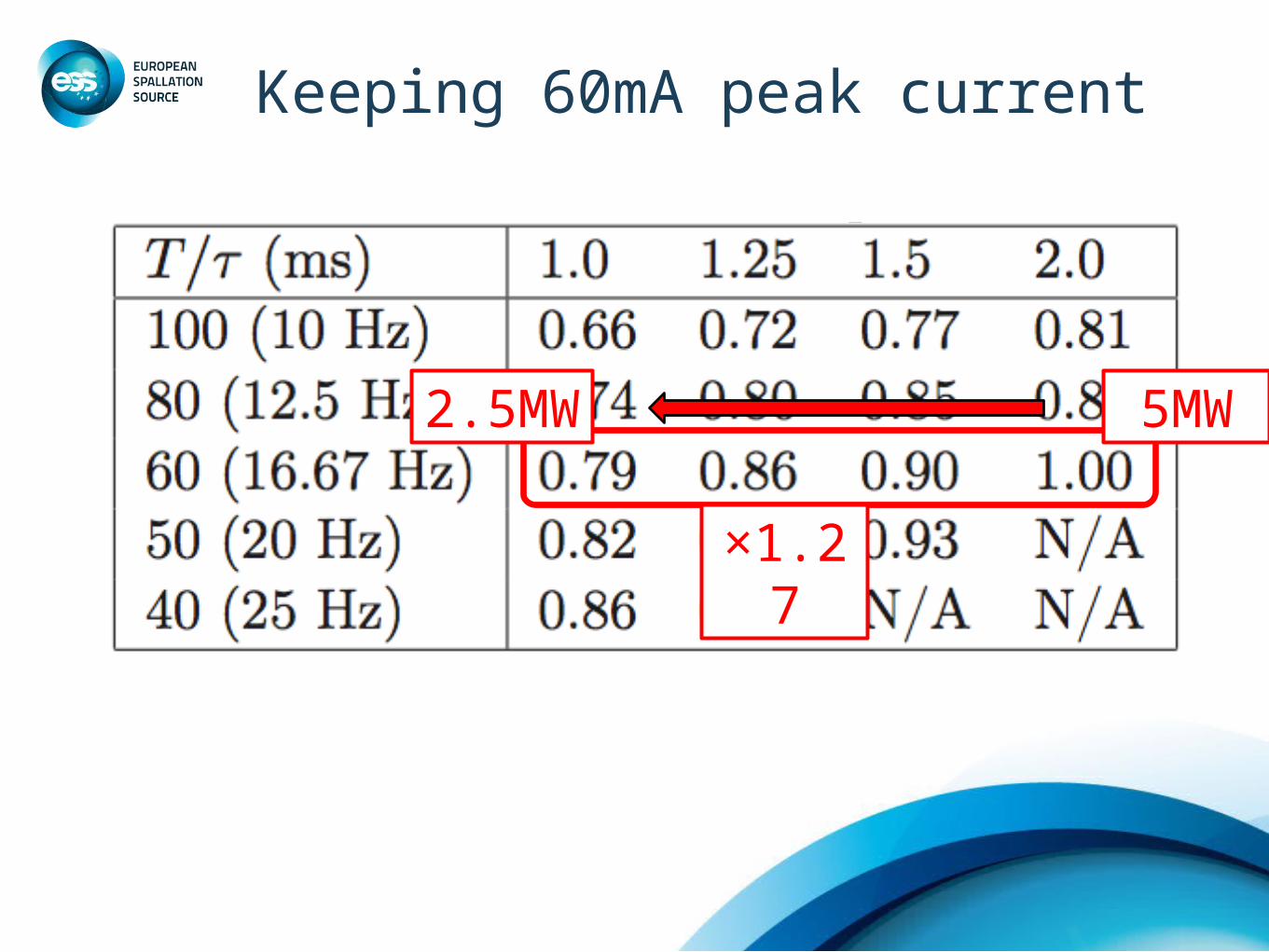
Keeping 60mA peak current
5MW2.5MW
×1.27
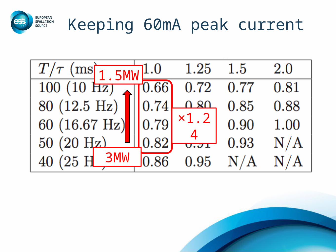
Keeping 60mA peak current
3MW
×1.24
1.5MW
Keeping 60mA peak current
3MW
×1.24
1.5MW
€
Performance ∝ Paverage0.3
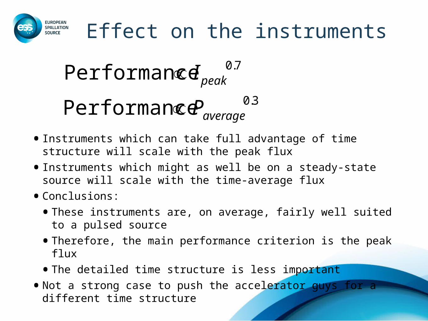
Effect on the instruments
• Instruments which can take full advantage of time structure will scale with the peak flux
• Instruments which might as well be on a steady-state source will scale with the time-average flux
• Conclusions:
• These instruments are, on average, fairly well suited to a pulsed source
• Therefore, the main performance criterion is the peak flux
• The detailed time structure is less important
• Not a strong case to push the accelerator guys for a different time structure
€
Performance ∝ Ipeak0.7
€
Performance ∝ Paverage0.3
Thank you to all involved!
Ken Andersen
Instruments Division Head
Science Directorate
ESS Science Advisory Committee
Lund 2010-11-04