J TRMS AC DC CAT · AC DC AC&DC Grounding CAT. II 600 V over voltage protection CAT. III 300 V over...
7
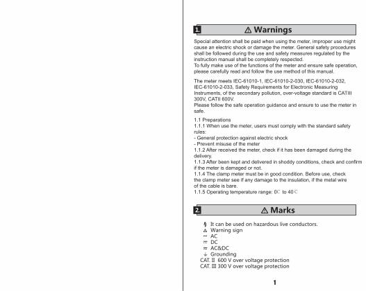
CAT Ɋ 300V . V Alert ~ LIVE A A V μ COM INPUT ! CAT 300V MAX 600V CAT 600V TRMS AC TDC CLAMP METER
Transcript of J TRMS AC DC CAT · AC DC AC&DC Grounding CAT. II 600 V over voltage protection CAT. III 300 V over...

CAT300V
.
V Alert~
LIVE
A
A
V
μ
COM INPUT! CAT 300V
MAX 600V
CAT 600V
TRMS AC DC CLAMP METER
1
1. Warnings
It can be used on hazardous live conductors. Warning sign AC DC AC&DC GroundingCAT. II 600 V over voltage protectionCAT. III 300 V over voltage protection
~...~
2. Marks
Special attention shall be paid when using the meter, improper use might cause an electric shock or damage the meter. General safety procedures shall be followed during the use and safety measures regulated by the instruction manual shall be completely respected.To fully make use of the functions of the meter and ensure safe operation, please carefully read and follow the use method of this manual.
The meter meets IEC-61010-1, IEC-61010-2-030, IEC-61010-2-032, IEC-61010-2-033, Safety Requirements for Electronic Measuring Instruments, of the secondary pollution, over-voltage standard is CATIII 300V, CATII 600V.Please follow the safe operation guidance and ensure to use the meter in safe.
1.1 Preparations1.1.1 When use the meter, users must comply with the standard safety rules:- General protection against electric shock- Prevent misuse of the meter1.1.2 After received the meter, check if it has been damaged during the delivery.1.1.3 After been kept and delivered in shoddy conditions, check and confirm if the meter is damaged or not.1.1.4 The clamp meter must be in good condition. Before use, check the clamp meter see if any damage to the insulation, if the metal wire of the cable is bare.1.1.5 Operating temperature range: 0℃ to 40℃
2 3
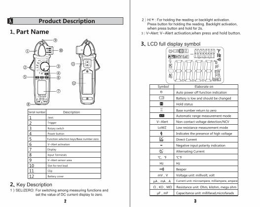
3. Product Description
1
2
3Serial number
Description
Jaws1 2 Trigger
3 Rotary switch
4 Power button
5 Function selection keys/Base number zero
V~Alert activation6 7 Display
8 Input Terminals
9 V~Alert sensor area
10 Slot for test lead
11 Clip
12 Battery cover
1 SEL/ZERO: For switching among measuring functions and set the value of DC current display to zero.
2 H/ : For holding the reading or backlight activation.Press button for holding the reading. Backlight activation,when press button and hold for 2s.
3 V~Alert: V~Alert activation,when press and hold button.
Symbol Elaborate on
Auto power off function indication
Battery is low and should be changed
Hold status
Base number return to zero
Automatic range measurement mode
V~Alert Non-contact voltage detection/NCV
LoWZ Low resistance measurement mode
Indicates the presence of high voltage
Direct Current
Negative input polarity indication
Alternating Current
Hz Hz
Beeper
Voltage unit: millivolt, volt
Current unit: microampere, milliampere, ampere
Capacitance unit: millifarad,microfarads
H
AUT
DC...
AC~
V Alert~
LIVE
A
A
V
μ
COM INPUT! CAT 300V
MAX 600V
CAT 600V
TRMS AC DC CLAMP METER
Part Name
Key Description
LCD full display symbol
11
12
Serial number
4 5
1. Current DC
Range Resolution
ResolutionRange
Resolution
Resolution
Resolution
Resolution
Resolution
Resolution
Resolution
Range
Range
Range
Range
Range
Range
Range
5. Voltage DC
6V 0.001V60V 0.01V600V 0.1V
6V 0.001V60V 0.01V600V 0.1V
600V 0.1V ±1.0%
±1.0%
600V 0.1V
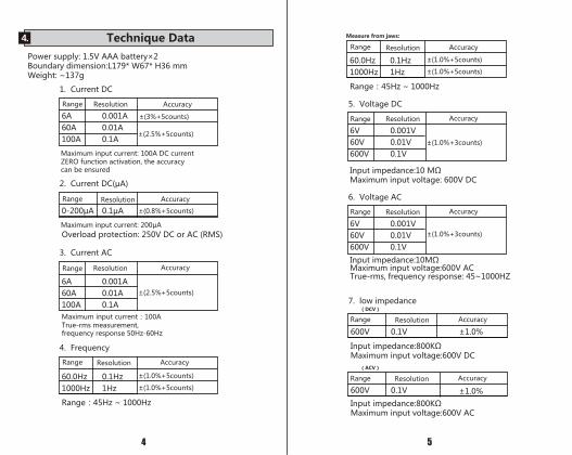
Measure from jaws: 4.
V Alert~
LIVE
A
A
V
μ
6 7
R
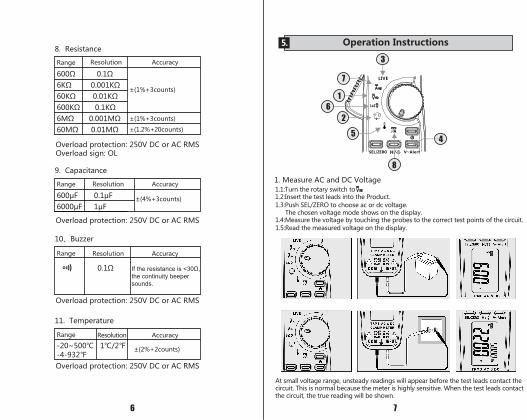
8. Resistance
Overload protection: 250V DC or AC RMSOverload sign: OL
V. :Turn the rotary switch to .2:Insert the test leads into the Product..3:Push SEL/ZERO to choose ac or dc voltage.
The chosen voltage mode shows on the display..4:Measure the voltage by touching the probes to the correct test points of the circuit..5:Read the measured voltage on the display.
At small voltage range, unsteady readings will appear before the test leads contact the circuit. This is normal because the meter is highly sensitive. When the test leads contact the circuit, the true reading will be shown.
9. Capacitance
Overload protection: 250V DC or AC RMS
Overload protection: 250V DC or AC RMS
Overload protection: 250V DC or AC RMS
the continuity beeper sounds.
5. Operation Instructions
Voltage
1
26
8
3
45
7
Range AccuracyResolution
AccuracyResolution
AccuracyResolution
AccuracyResolution
Range
Range
Range
±( .2 20counts
8 9
RR
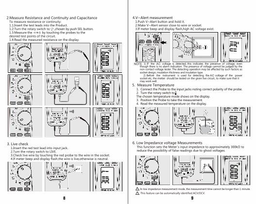
2.Measure Resistance and Continuity and CapacitanceTo measure resistance or continuity:1.1:Insert the test leads into the Product.1.2:Turn the rotary switch to ,chosen by push SEL button.1.3:Measure the by touching the probes to the desired test points of the circuit.1.4:Read the measured resistance on the display.
3. Live check1.Insert the red test lead into input jack.2.Turn the rotary switch to LIVE.3.Check live wire by touching the red probe to the wire in the socket.4.If meter beep and display flash,the wire is live,otherwise is neutral.
1.Push V~Alert button and hold it.2.Make V~Alert sensor close to wire or socket.3.If meter beep and display flash,high AC voltage exist.
4.V~Alert measurement
5. Measure Temperature
meter
NOTE:
1. Connect the Probe to the input jacks noting correct polarity of the probe. 2. Turn the rotary switch to . The chosen temperature mode shows on the display.3. Position the Probe to take the measurement. 4. Read the measured temperature on the display.
6. Low Impedance voltage Measurements
reduce the possibility of false readings due to ghost voltages.
In low impedance measurement mode, the measurement time cannot be longer than 1 minute.
This feature can be automatically identified ACV/DCV.
!
!
R
10
6. Maintenance
11
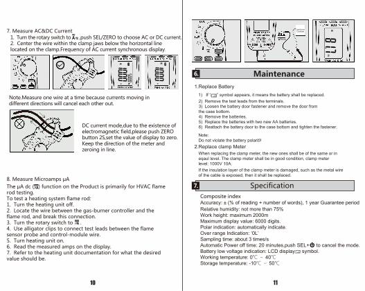
Gas BurnerController
Burner1. Tur he ro ary swi ch o ,push SEL/ZERO o choose r curre .2. e er he wire wi hi he clamp jaws below he horizo al li eloca ed o he clamp.Freque cy of curre sy chro ous display.
No e.Measure o e wire a a ime because curre s movi g i
curre mode,due o he exis e ce ofelec romag e ic field,please push ZERO bu o 2S,se he value of display o zero.Keep he direc io of he me er a d zeroi g i li e.
differe direc io s will ca cel each o her ou .
A
1.Replace Battery
2.Replace clamp MeterWhen replacing the clamp meter, the new ones shall be of the same or in eqaul level. The clamp meter shall be in good condition, clamp meter level: 1000V 10A.If the insulation layer of the clamp meter is damaged, such as the metal wire of the cable is exposed, then it shall be replaced.
1) If “ ” symbol appears, it means the battery shall be replaced.2) Remove the test leads from the terminals.3) Loosen the battery door fastener and remove the door fromthe case bottom.4) Remove the batteries.5) Replace the batteries with two new AA batteries.6) Reattach the battery door to the case bottom and tighten the fastener.
Note:Do not violate the battery polarity.
value should be.
Aμ
Aμ
7.
Accuracy: ± (% of reading + number of words), 1 year Guarantee period Relative humidity: not more than 75%Work height: maximum 2000mMaximum display value: 6000 digits.Polar indication: automatically indicate.Over range Indication: ‘0L’ Sampling time: about 3 times/sAutomatic Power off time: 20 minutes,push SEL+ to cancel the mode.Battery low voltage indication: LCD display symbol.Working temperature: 0 40Storage temperature: -10 50